Article

The Bearing Performance and Sectional Design Method of Yielding U-Shaped Steel Support

1
School of Mechanics and Engineering, China University of Mining and Technology-Beijing, Beijing 100083, China
2
National Key Laboratory of Disaster Prevention and Control and Intelligent Construction of Tunnel Engineering, China University of Mining and Technology-Beijing, Beijing 100083, China
3
School of Civil Engineering, Shandong University, Jinan 250061, China
4
Shandong Tangkou Coal Industry Co., Ltd., Jining 272055, China
*
Authors to whom correspondence should be addressed.
Appl. Sci. 2025, 15(6), 3203; https://doi.org/10.3390/app15063203
Submission received: 8 January 2025 / Revised: 6 March 2025 / Accepted: 12 March 2025 / Published: 14 March 2025

Abstract

:
The bearing capacity and yieldable performance of yielding U-shaped steel support are difficult to be fully exerted in roadways under complex conditions, and serious deformation and damage occur frequently. Taking the mining roadways of Tangkou Coal Mine in a kilometer-deep well as the engineering background, this paper summarizes and analyzes the typical failure modes of the on-site yielding U-shaped steel support. By utilizing the independently developed full-scale arch frame test system, the bearing performance tests of arch frames with different sectional methods were carried out. The results show that compared with the three-section U-shaped steel support, the yieldable performance of the four-section support is increased by 21.8%, while the bearing capacity is only decreased by 1.9%. Furthermore, numerical tests on yielding U-shaped steel support under different load patterns and different cross-sectional forms were conducted to clarify the deformation characteristics and internal force distribution laws of U-shaped steel support under complex stress conditions. Finally, a sectional design method for yielding U-shaped steel support and on-site engineering suggestions were put forward. Based on this methodology, it is feasible to optimize the support structure scheme that better matches the engineering geological conditions, thereby fully utilizing the yielding characteristics and load-bearing capacity of the support. This approach effectively prevents premature local failure of the support, extends its service life, and enhances the safety of roadway support engineering while achieving significant economic benefits.

1. Introduction

With the depletion of shallow coal resources in China, coal mining has been developing towards deeper strata [1]. Deep coal mining is faced with complex geological conditions such as high stress and extremely soft rock. The surrounding rock of roadways deforms significantly and the deformation lasts for a long time. Traditional high-strength rigid support is difficult to effectively adapt to the large deformation of the surrounding rock [2,3,4,5,6,7,8,9,10,11,12,13]. Yieldable support not only provides support resistance to maintain the stability of the surrounding rock but also allows the support structure to generate an appropriate amount of deformation to relieve the pressure on the surrounding rock. It has been widely used in deep soft rock engineering projects. Common yieldable support structures include high-toughness bolts, flexible steel meshes, and retractable support [14,15]. Among them, the yielding U-shaped steel support has the advantages of high resistance, retractability, and convenient installation, and it is a commonly used form of yieldable support.
In the actual application process, due to the complexity of the stress environment, the yielding U-shaped steel support is prone to yield failure first at the stress concentration positions, resulting in difficulty in fully exerting its yieldable and bearing performances [16]. To improve the bearing and yieldable performance of the yielding U-shaped steel support and enhance the surrounding rock control effect, scholars at home and abroad have carried out a large number of related studies. Xu Lianman et al. [17,18] studied the sliding mechanism of the lapped section of the U-shaped steel, tested the friction performance between different materials at the nodes of the U-shaped steel support, and proposed an optimization method for improving the sliding performance of the lapped section, which improved the retractable performance at the lapped part of the U-shaped steel support. Xie Wenbing et al. [19] analyzed the main reasons for the structural instability of the U-shaped steel support, put forward a support stable-resistance technology, the compensation principle and compensation technology of the support structure, and improved the overall bearing capacity and structural stability of the U-shaped steel support. Yao Zhishu et al. [20] analyzed the influence of factors such as backfill behind the wall, torque of cable clamp nuts, and longitudinal tie rods on the overall bearing capacity of the U-shaped steel support, and proposed improvement measures for the overall bearing capacity of the support. Wang Qizhou et al. [21] analyzed the instability characteristics of the U-shaped steel support under different loading conditions, and proposed the combined support technology of “U-shaped steel support + backfill behind the wall + anchor cable”, which improved the stability of the surrounding rock of the roadway under the influence of intense mining. Ma Zhenqian et al. [22] studied the load distribution law of the support and the deformation characteristics of the roadway before and after the implementation of pressure relief boreholes, and proposed the control measures of “shed support + pressure relief” for the roadway in extremely soft coal seams, which improved the stress state of the U-shaped steel support. Yu-Yong Jiao et al. [23] improved the U-shaped steel connecting sleeve and proposed the support system of “metal mesh + backfilled chemical grouting material + U-shaped steel group”, which ensured the stability of the surrounding rock of deep roadways. Horyl P et al. [24] found that the bearing capacity of U-shaped steel supports and the ability to withstand deformation of surrounding rock are largely dependent on the action of the connection, and the preload generated by the bolts under different torques was studied by 2010 ANSYS software. Jarosław, B. et al. [25] investigated the influence mechanism of friction effects at support joints under impact loading, developing a friction joint model and testing system to guide support design. Łukasz Bednarek et al. [26], to solve the problem of excessive deformation of the surrounding rock of the roadway in the process of coal longwall mining, proposed the joint support measure of “U-shaped steel support + anchor”, and the field application results showed that the deformation of the surrounding rock of the roadway was effectively improved. Marek Rotkegel et al. [27] studied the mechanical deformation characteristics of U-shaped steel supports under different loads through laboratory tests and numerical simulations, which provided guidance for the selection of on-site arch structures and roadway excavation conditions.
The above studies have improved the bearing performance and stress state of the yielding U-shaped steel support by optimizing the form of support nodes and adopting combined support measures. However, due to the complexity of deep soft rock projects, the influence mechanism of the bearing performance of the yielding U-shaped steel support is still unclear, and the sectional design remains at the stage of on-site experience, without fully considering the influence of the sectional position on the yieldable and bearing performance. Therefore, it is necessary to conduct research on the influence mechanism of the bearing performance of the yielding U-shaped steel support and its sectional design under complex environments.
Based on this, taking the mining gateway of Tangkou Coal Mine in a kilometer-deep well as the engineering background, this paper conducts a statistical analysis of the failure forms of U29 steel support on site. By using the independently developed full-scale support mechanical test system, indoor tests on full-scale yielding U-shaped steel support with different sectional methods are carried out, as well as numerical tests on the bearing performance of yielding U-shaped steel support under different load patterns and different cross-sectional forms. The deformation and internal force distribution laws of the support under different conditions are analyzed, and a sectional design method for yielding U-shaped steel support is proposed to guide the on-site design.

2. Analysis of Typical On-Site Failure Modes of Yielding U-Shaped Steel Support

In this section, the failure forms of the support in the track gateway of the 6315 working face in Tangkou Coal Mine are investigated, and the typical failure modes and causes of yielding U-shaped steel support are analyzed.

2.1. Project Overview

Tangkou Coal Mine has a designed production capacity of 3 million tons per year [28]. In the coalfield, folds are well developed, there are numerous faults, and the geological structure is complex. The 6315 working face of this mine is buried at a depth of 990 m. The maximum horizontal principal stress is as high as 38.62 MPa, and the average horizontal principal stress is 34.04 MPa. The roof and floor of the coal seam are mostly mudstone, siltstone, and fine-grained sandstone, and the overall rock mass conditions are relatively poor.
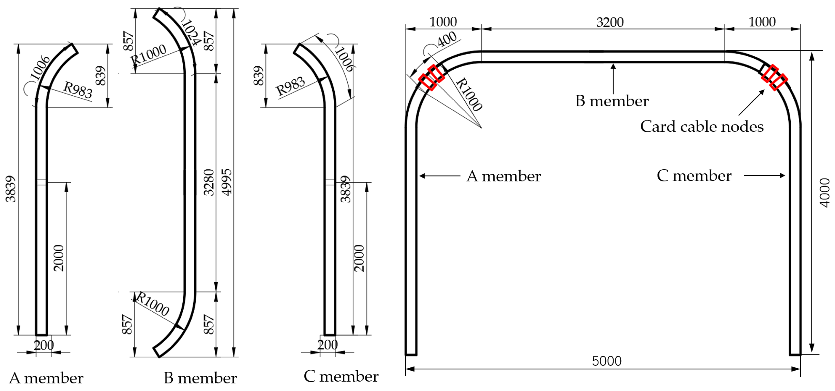
The cross-sectional shape of the gateway roadway is rectangular, with a net width of 5000 mm and a net height of 4000 mm. A combined support form of “U-shaped steel support + bolt-mesh-shotcrete” is adopted. The bolts are Φ22 × 2800 mm bolts, with a spacing and row spacing of 1000 (600) × 1000 mm. The diameter of the anchor cable is 21.8 mm and the length is 8200 (4200) mm, with a spacing and row spacing of 1200 (800) × 1000 mm. A three-section U29 steel support is used, and the spacing between the supports is 800 mm. The lap length of each node is 400 mm, and two cable clamps are equipped. The design of the roadway section and support parameters is shown in Figure 1, and the design drawing of the U29 steel support is shown in Figure 2.

2.2. Typical Failure Analysis

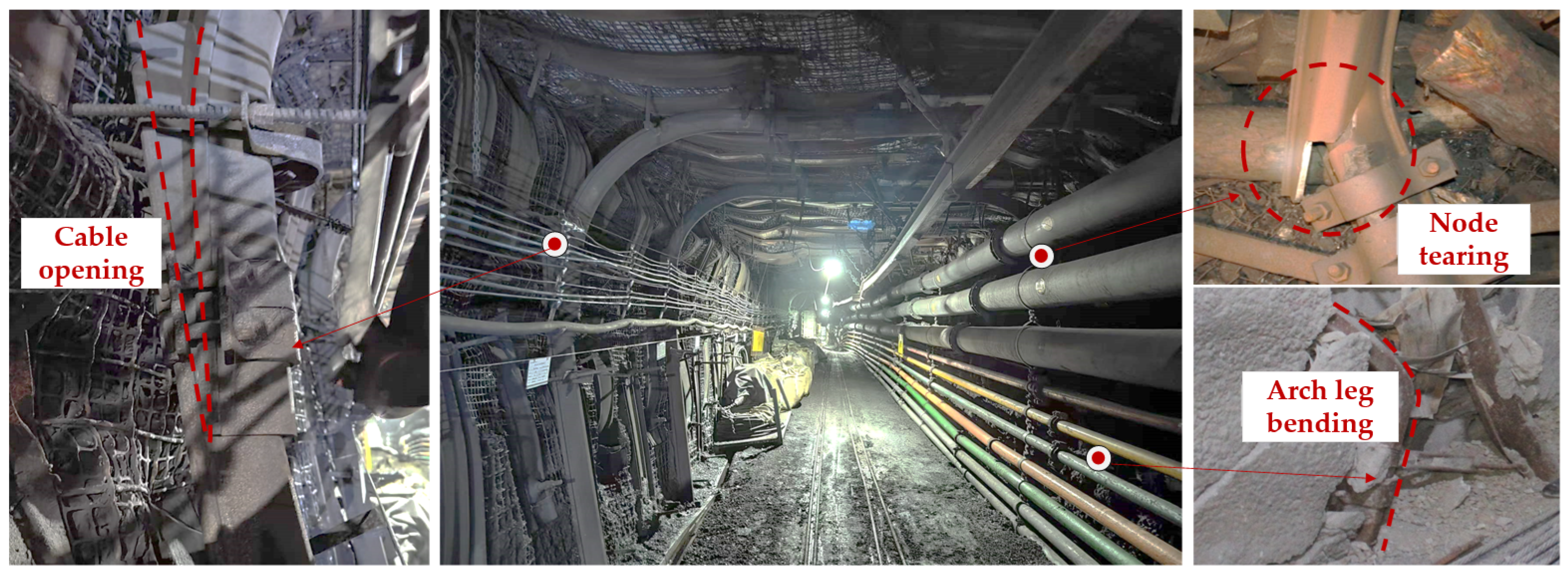
During the mining period of the 6315 working face, affected by the abutment pressure in advance and the influence of mining activities, the roadway within 50 m in front of the working face deformed seriously. The maximum convergence amount between the roof and the floor exceeded 450 mm. The U-shaped steel support did not show obvious yieldable deformation at the cable clamp nodes. Failure phenomena such as breakage of cable clamp bolts, fracture of the support at the nodes, and overall buckling deformation of the support occurred. The typical on-site failure situation is shown in Figure 3.
Based on the analysis of the on-site failure characteristics, it can be known that:
  • The bending moment at the nodes is large and is difficult to yield. The cable clamp nodes are designed near the bent parts of the support. At this position, the bending moment is large, and the cable clamp nodes are in an open state, making it difficult for the nodes to retract and yield.
  • Stress concentration occurs at the nodes, resulting in structural tearing. The failures at the cable clamp nodes are mostly manifested as the tearing of the support, the fracture of screw rods, the outward turning of cable clamps, and the breakage of clamping plates. The main reason is that the combined structure at the nodes is complex, stress concentration occurs easily, and structural failures are prone to happen at the nodes.
  • The support is subjected to asymmetric forces, resulting in buckling failures. Under the action of asymmetric loads, the support as a whole shows asymmetric failure characteristics. The deformation on the side of the small coal pillar is greater than that on the side of the solid rib. Straight-leg buckling and shoulder bending of the support occur, and the bearing capacity of the support is difficult to be fully exerted.
In conclusion, in engineering projects under deep and complex conditions, yielding U-shaped steel supports are prone to stress concentration and large bending moments at the nodes, which leads to a difficulty for the nodes to retract and causes local structural failures. As a result, the overall bearing performance cannot be effectively exerted. To improve the yield effect at the nodes and enhance the bearing performance of the support, it is necessary to further clarify the internal force and deformation distribution states of yielding U-shaped steel support under complex stress environments.

3. Indoor Experimental Research on the Bearing Performance of Yielding U-Shaped Steel Support

Using the independently developed full-scale arch frame test system, in this section, bearing performance tests of arch frames with different sectional methods are carried out to study the influence of sectional methods on the bearing performance of arch frames.

3.1. Experimental Scheme

3.1.1. Experimental System

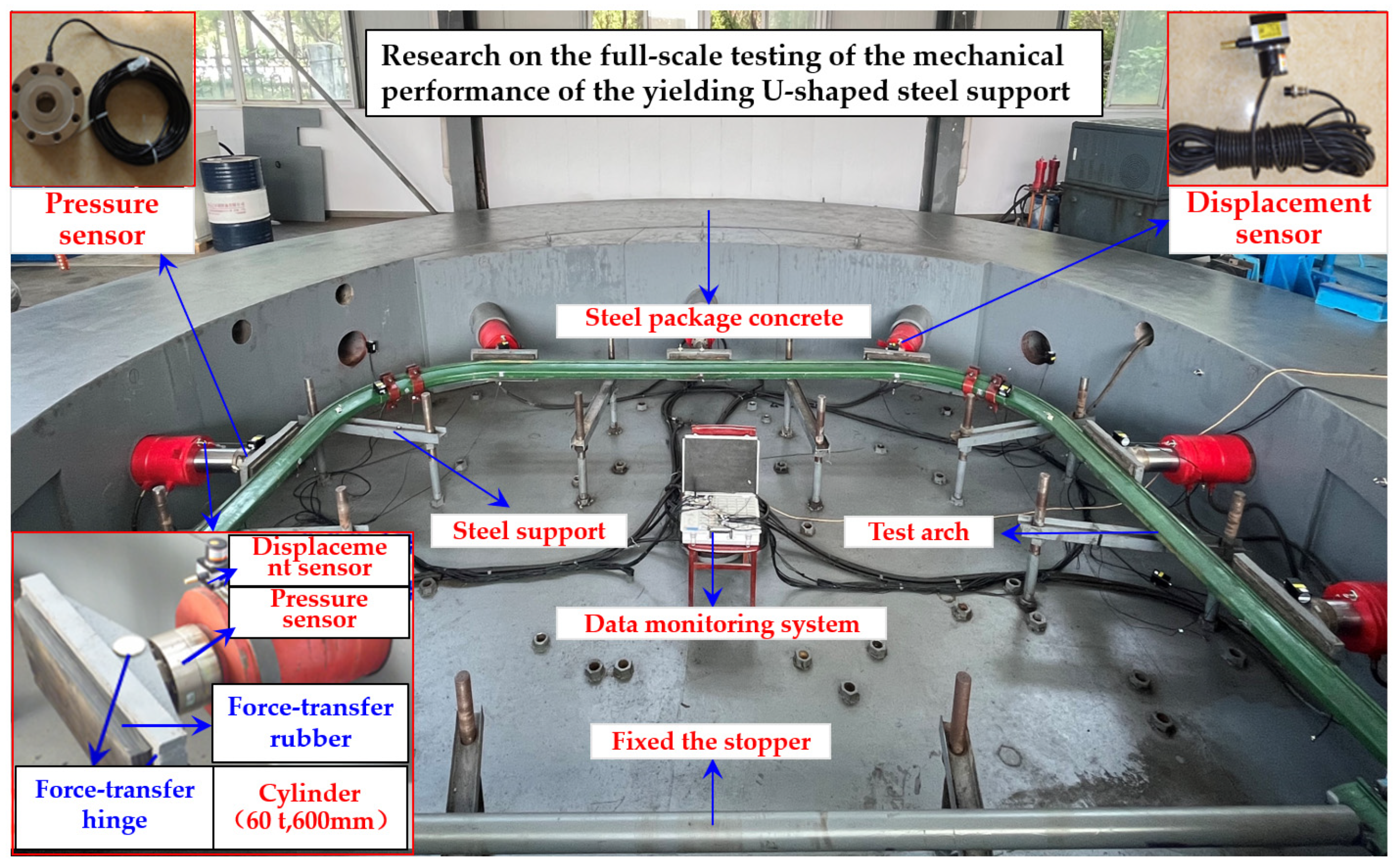
The maximum outer diameter of the full-scale support mechanical test system is 10 m and the inner diameter is 6 m. The reaction structure around it is composed of steel plates wrapped with concrete, which has high strength, large stiffness, and good stability, and can meet the requirements of 1:1 support mechanical tests for mine roadways [29]. Meanwhile, the test system is equipped with different combined modules, which can realize the loading of support with different cross-sectional shapes. The loading system mainly consists of a hydraulic pump station, a loading force distributor, 12 groups of 200 t loading cylinders, an automatic control system, and a monitoring system, etc., and can achieve the ultimate loading requirement of 2400 t. The overall situation of the test system is shown in Figure 4.

3.1.2. Loading Scheme

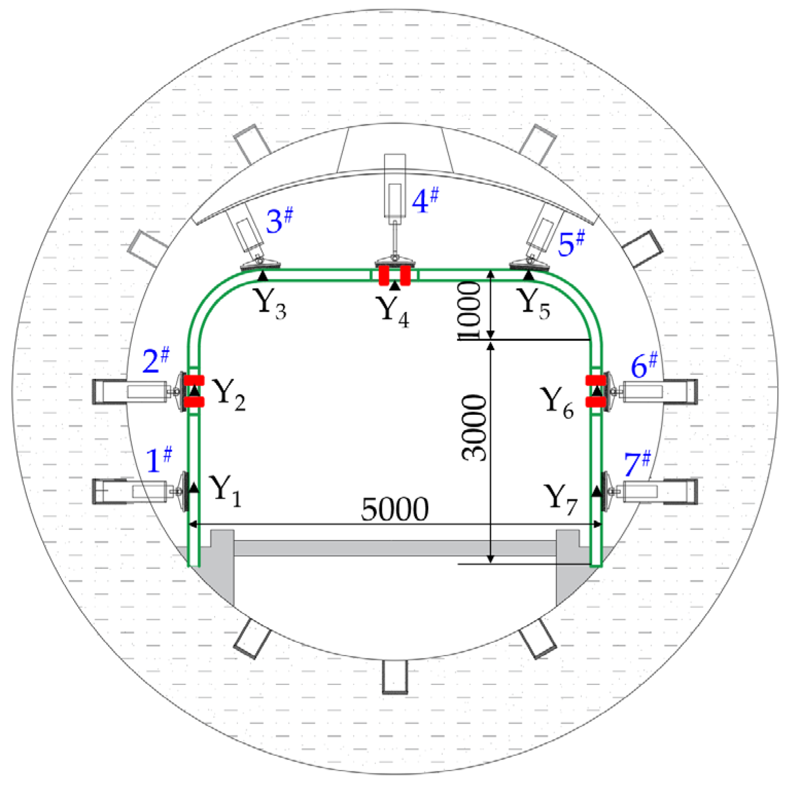
Seven cylinders are used for loading in the experiment. There are three cylinders on the top and two cylinders on each of the straight legs on both sides. A graded loading method is adopted to apply a uniform load on the support. The loading rate is 10 kN/min, and the pressure is maintained for 0.5 min every 30 kN. During the loading process, the failure situation of the test specimens is observed at all times, and the stress, deformation of the support and compression amount of the nodes are monitored until the test specimens as a whole enter the yielding state or obvious failures occur, and then the loading is stopped. The sectional division and loading of the three-section and four-section support are shown in Figure 5.

3.1.3. Monitoring Scheme

In order to effectively monitor and collect the stress and deformation of the support during the test process, pressure and displacement sensors are arranged on the 1#~7# loading cylinders to monitor the stress and deformation of the support. Strain gauges numbered Y1–Y9 are pasted on the support, and the layout of the monitoring points is shown in Figure 5.

3.2. Analysis of Test Results

Through carrying out the mechanical performance tests on full-scale yielding U-shaped steel support, the stress and deformation characteristics of three-section and four-section U-shaped steel support are obtained. The deformation failure modes, yieldable effects, and bearing performances of U-shaped steel support at different sectional positions are compared and analyzed.

3.2.1. Analysis of the Deformation and Yielding Process

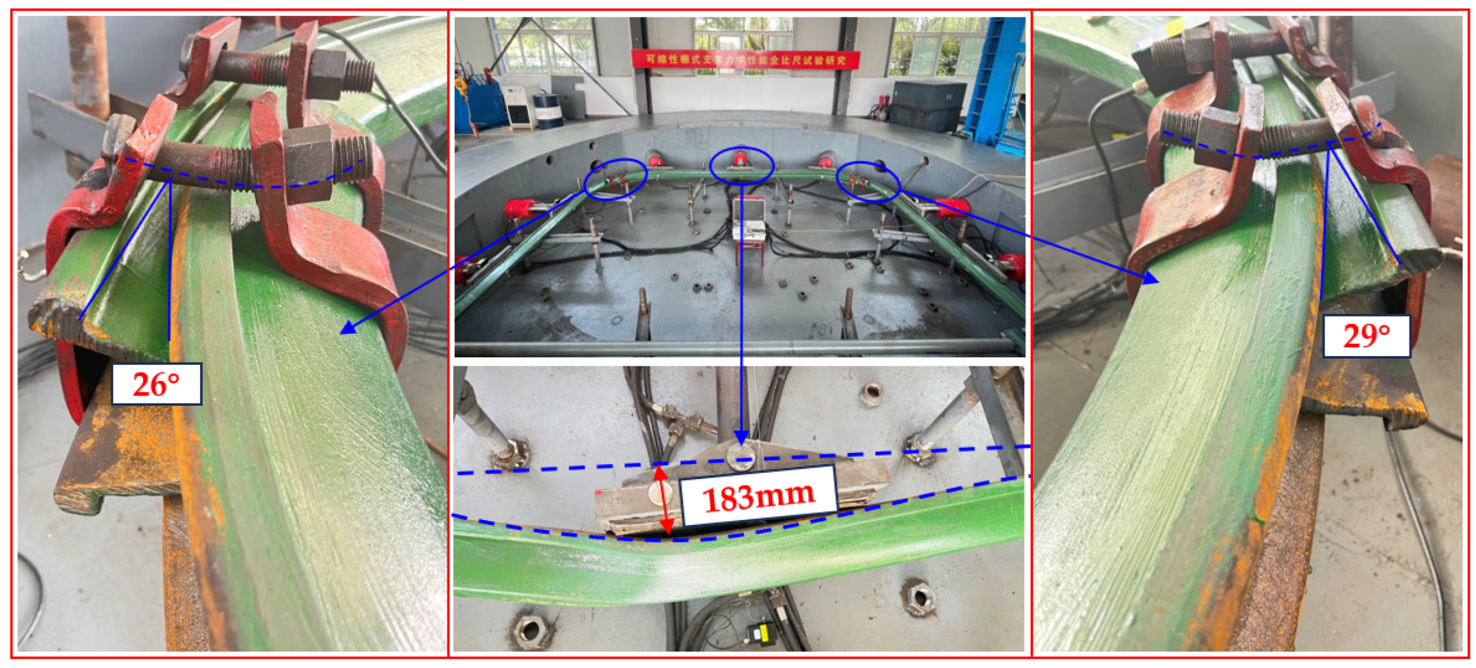
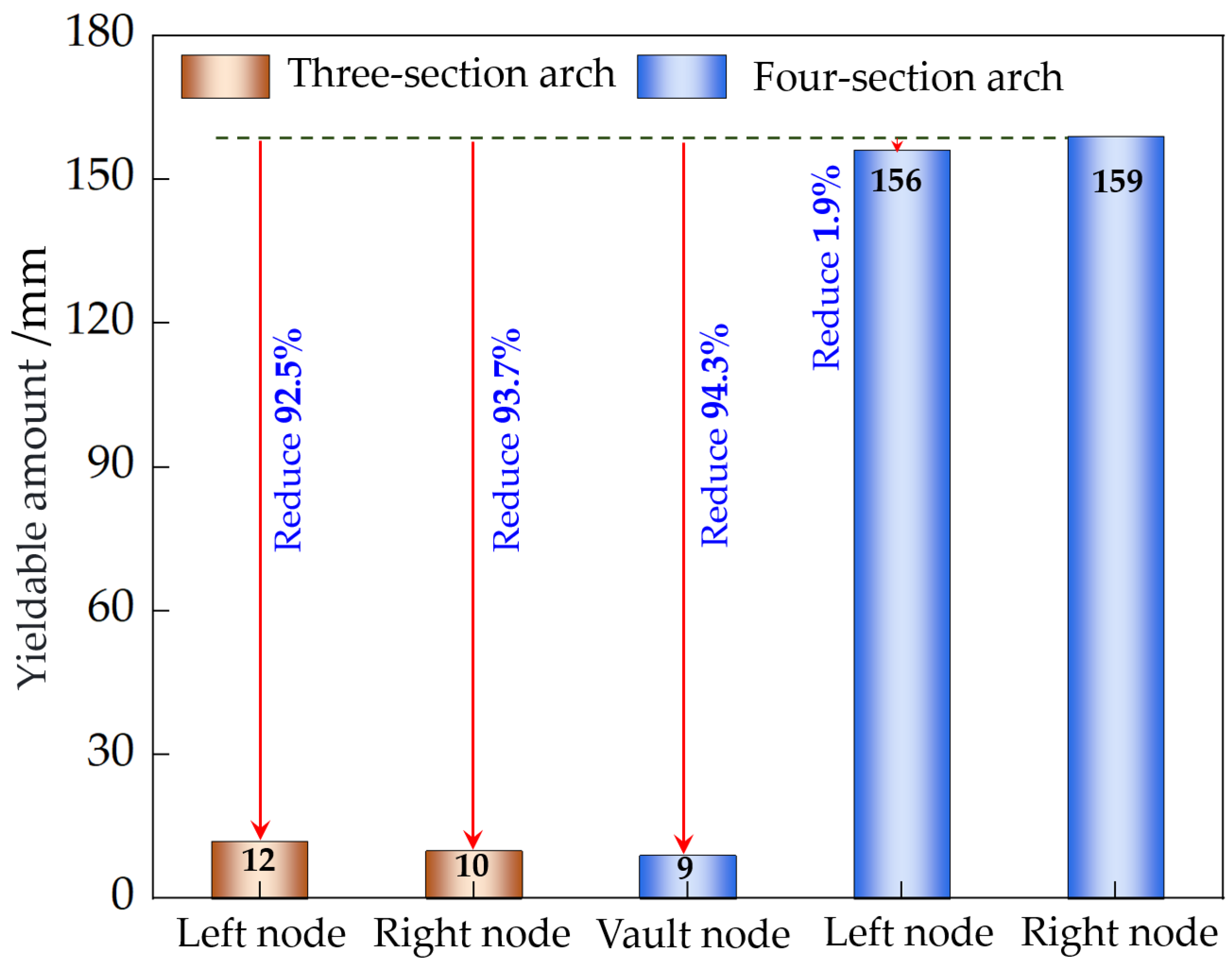
The overall and local deformation patterns of the three-section and four-section support are shown in Figure 6 and Figure 7, respectively. The comparison of the maximum deformation amounts of the top and the straight legs is shown in Figure 8, and the comparison of the yieldable amounts of the support nodes is shown in Figure 9.
  • Analysis of Support Deformation
The three-section U-shaped steel support as a whole presents an “M”-shaped deformation pattern with a top sinking. Obvious buckling failures occur in the middle of the top, such as bulging deformation and paint peeling, and bending deformation appears on the straight legs on both sides. After measurement, the deflection of the top is 183 mm and the inward deformation of the two straight legs is 47 mm and 51 mm in sequence. The top of the four-section U-shaped steel support settles, and the left and right straight legs do not have obvious deformation, while the whole is symmetrical left and right. After measurement, the deflection of the top is 76 mm and the inward deformation of the two straight legs is 9 mm and 11 mm in sequence. Compared with the three-section support, the deflection of the top corresponding to the maximum bearing capacity of the four-section support is reduced by 58.5%.
2.
Analysis of Node Yielding
Before reaching the maximum bearing capacity, the three-section U-shaped steel support does not have obvious yielding deformation, and the slip amounts at the nodes on both sides are only 12 mm and 10 mm. The cable clamps at the lapped parts of the support turn outward, the screw rods are pulled and bent, mainly with an open-type rotation. The opening angles of the two lapped steel sections are 26° and 29°, respectively. Before reaching the maximum bearing capacity, the nodes of the two straight legs of the four-section U-shaped steel support first generate yielding slip and keep increasing. The node slip amounts are 156 mm and 159 mm, respectively. The top node first generates slip and then turns outward. The node compression amount is 9 mm and the opening angle is 12°. Compared with the three-section support, the node yielding effect corresponding to the maximum bearing capacity of the four-section support is significantly improved.

3.2.2. Analysis of Support Bearing Capacity

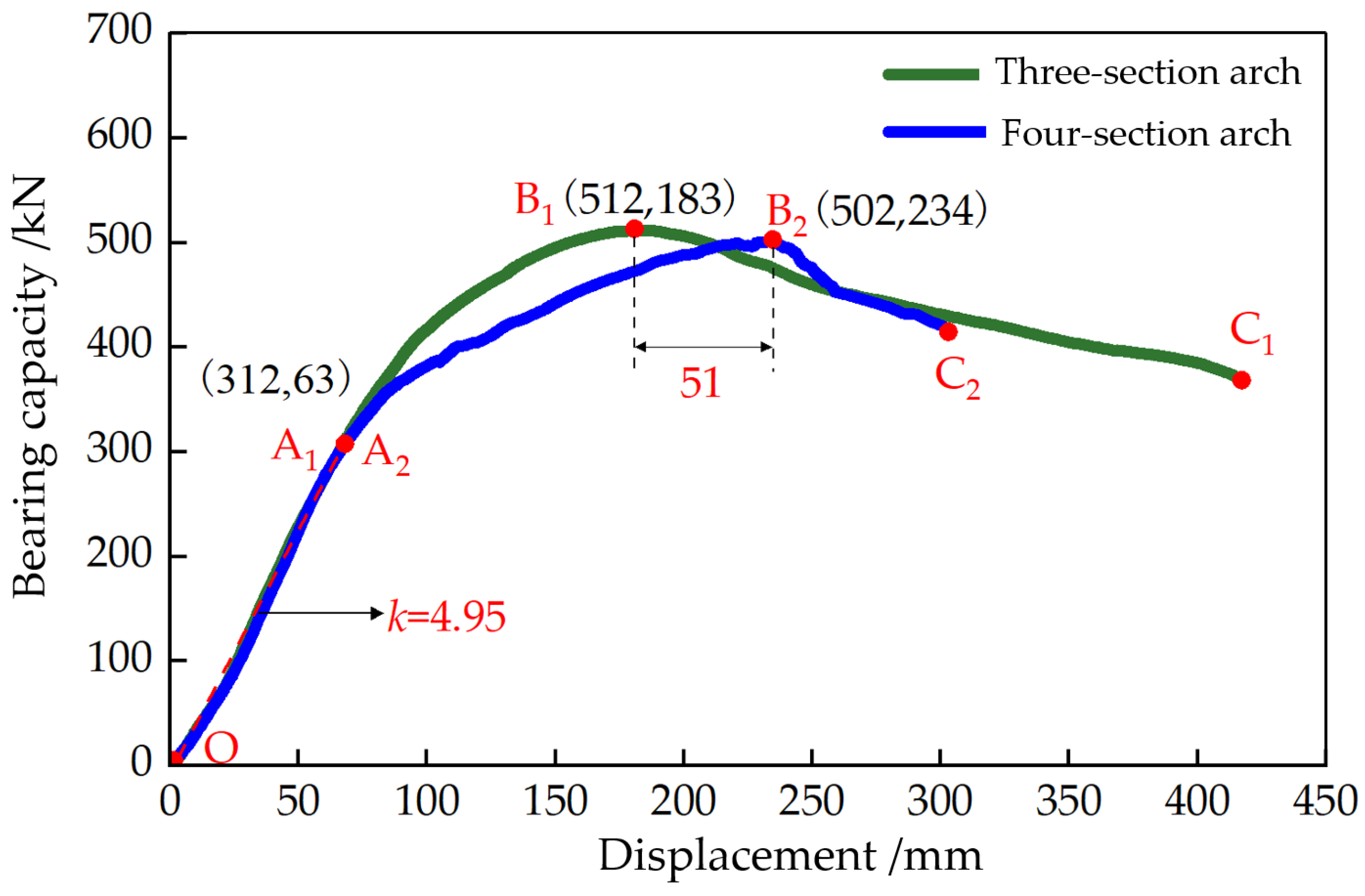
The bearing capacity–displacement relationship curves of the three-section and four-section support are shown in Figure 10, and a comparison of the peak bearing capacity and the peak deformation is shown in Figure 11. Among them, the bearing capacity is the sum of the loads of each cylinder and the displacement is taken at the position of the fourth cylinder where the deformation is the largest.
It can be seen from Figure 10 that under the condition of a uniform load, the bearing process of the support can be divided into the elastic bearing stage, the yieldable bearing stage, and the post-peak bearing stage.
Elastic Bearing Stage (OA1, OA2): The bearing capacity and displacement are basically in a linear relationship and the bearing capacity-displacement curves of the three-section and four-section support basically coincide, indicating that no slip occurs at the nodes in this stage. Yieldable Bearing Stage (A1B1, A2B2): The slope of the bearing capacity–displacement curve decreases and the bearing capacity–displacement curve of the four-section support tends to be flat. In this stage, the retractable nodes begin to play a yieldable role. The deformation amount of the four-section support in this stage is 51 mm larger than that of the three-section support. After this stage ends, the supports reach their respective ultimate bearing capacities. Post-peak Bearing Stage (B1C1, B2C2): After the supports reach their ultimate bearing capacity, with the continuous loading the supports enter the yielding state, the deformation increases rapidly, and the bearing capacity drops rapidly.
It can be seen from Figure 11 that the ultimate bearing capacities of the three-section and four-section support are 512 kN and 502 kN, respectively, and the maximum deformation corresponding to the ultimate bearing capacities are 183 mm and 234 mm, respectively. Compared with the three-section support, the yieldable performance of the four-section support is increased by 21.8% and the bearing capacity is only reduced by 1.9%. It shows that the four-section support improves the yieldable performance without a significant reduction in the bearing capacity, which verifies the rationality of the proposed sectional design method for yielding U-shaped steel support.

4. Analysis of the Influence Mechanism on the Bearing Performance of Yielding U-Shaped Steel Support

In this section, numerical tests on U-shaped steel support under different stress modes and different cross-section forms are carried out. By analyzing the internal force distribution and deformation characteristics of the support, the influence mechanism on the bearing performance of U-shaped steel support is clarified.

4.1. Experimental Scheme and Model Establishment

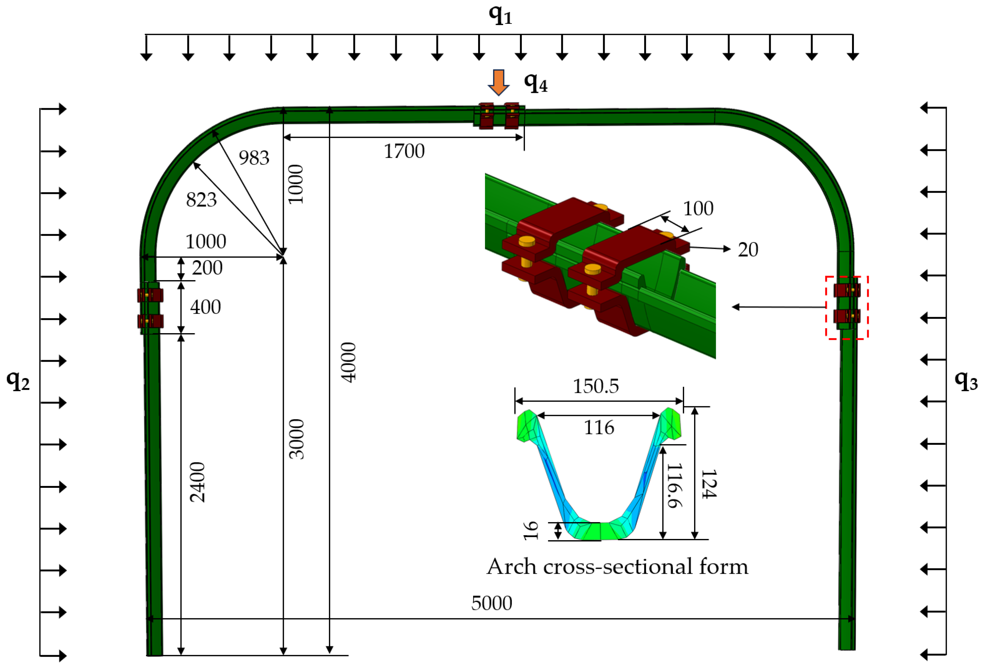
Taking the cross-sectional size and sectional method of the U29 steel support on the site of Tangkou Coal Mine as references, a numerical calculation model is established as shown in Figure 12. Two major categories of numerical tests, namely those with different cross-sectional shapes and different stress modes, are designed, as shown in Table 1.
In the schemes with different cross-sectional shapes: in Scheme A54, the width of the support is 5 m and the height is 4 m; in Scheme A45, the width of the support is 4 m and the height is 5 m; in Scheme A55, the width of the support is 5 m and the height is 5 m. In the schemes with different stress modes: in the symmetric load scheme with strong side pressure, H1: q1 = 1 MPa, q2 = 3 MPa, q3 = 3 MPa; in the symmetric load scheme with strong roof pressure, H2: q1 = 3 MPa, q2 = 1 MPa, q1 = 1 MPa; in the concentrated symmetric load scheme, H3: q4 = 20 MPa; in the left eccentric load scheme, H4: q1 = 1 MPa, q2 = 3 MPa, q1 = 1 MPa; and in the uniform load scheme, H5: q1 = q2 = q3 = 3 MPa.
Using the national standard data of U29 steel support for mining, the cross-section of U29 steel support was drawn in 2022 CAD software, imported into 2022 Abaqus software, and the finite element calculation model of the U-shaped steel arch was generated by stretching; in addition, the elastic–plastic strain-hardening constitutive model was selected, and in order to simplify the calculation, the constitutive model of the cable and bolt was set to linear elasticity, the mesh was selected as a hexahedral reduction integral, and the element type was C3D8R [30]. A load perpendicular to the outer surface of the support is applied and the bottom of the support is fixed, and all contacts are the surface with a friction coefficient of 0.3 [31]. According to the “GB-T4697-2017 hot-rolled section steel for mine roadway support” [32], the cross-sectional parameters and material parameters of the support are assigned, and the specific parameters are shown in Table 2 and Table 3.

4.2. Analysis of the Influence Mechanism on Bearing Performance

In order to analyze the deformation failure characteristics and internal force distribution forms of the support, the data on internal forces and deformation at different cross-sections are exported and the support deformation and internal force diagrams are drawn.

4.2.1. Influence Analysis of Load Forms

  • Analysis of Support Deformation under Different Stress Modes
In the schemes of different stress modes, the typical deformation patterns of the support are shown in Figure 13.
It can be known through an analysis of the support deformation diagrams that:
In the A54-H1 scheme, the maximum deformation of the support appears in the middle of the straight leg. The straight leg bends inward and there is a tendency for the top position to bulge upward. In the A54-H4 scheme, under the action of strong side pressure, the support inclines towards the side with weak side pressure, showing a “parallelogram” deformation pattern. In the A54-H2, A54-H3 and A54-H5 schemes, the deformation patterns of the support are basically the same. The maximum deformation of the support appears in the middle of the top of the support frame. The top of the support frame bends downward, showing an “M”-shaped failure pattern, and the deformation of the straight leg is not obvious.
The main reasons for this are as follows: When the horizontal load acting on the support is greater than the vertical load, the support as a whole is subjected to the bending moments in the horizontal inward and vertical downward directions. When the inward bending moment at the straight leg is greater than the downward bending moment at the top, the support first generates deformation at the straight leg. Conversely, when the downward bending moment is greater than the inward bending moment at the straight leg, the top first generates deformation. When the support is subjected to asymmetric horizontal loads, since the support is fixed at the bottom, the straight leg on the side with greater pressure starts to move towards the opposite side from the top position and finally shows a “parallelogram” failure pattern.
2.
Analysis of the Internal Forces of Support under Different Stress Modes
In the schemes of different stress modes, the typical internal force distributions of the support are shown in Figure 14.
It can be known through the analysis of the internal force diagrams of the support that:
In the A54-H1 scheme, the maximum axial force is 156 kN and the maximum bending moment is 59.8 kN·m; these are located at the top and the bottom foot, respectively. In the A54-H2 scheme, the maximum axial force is 135.7 kN and the maximum bending moment is 52.8 kN·m; these are located at the straight leg and the support shoulder, respectively. In the A54-H3 scheme, the maximum axial force is 63.3 kN, and the maximum bending moment is 50.2 kN·m; these are located at the straight leg and the support shoulder, respectively. In the A54-H5 scheme, the maximum axial force is 128.7 kN, and the maximum bending moment is 49.6 kN·m; these are located at the straight leg and the support shoulder, respectively.
The main reasons for this are as follows: When the horizontal load borne by the support is greater than the vertical load, the maximum axial force is located at the middle shoulder position of the top and the maximum bending moment is located at the bottom foot. When the horizontal load borne by the support is less than the vertical load, the maximum axial force is located in the middle of the straight leg and the maximum bending moment is located at the support shoulder position. When the support bears an asymmetric loads, both the maximum axial force and the maximum bending moment are distributed at the bottom foot position on the side with greater pressure. When the support bears a uniform load, the maximum axial force is located at the bottom foot and the maximum bending moment is at the support shoulder position.
3.
Analysis of Bearing Capacity–Displacement
Taking the middle of the straight leg in the A54-H1 scheme and the middle of the top in the A54-H2, A54-H3, A54-H4, and A54-H5 schemes, which are the dangerous deformation cross-sections, as examples, the relationship between the stress form of the support and the bearing capacity is analyzed. The bearing capacity–displacement relationship curves of the support are shown in Figure 15.
It can be known through the analysis of the bearing capacity–displacement curves of the support that:
The support failure has gone through three stages: linear elasticity (OA), plasticity (AB), and yield (BC). In the OA stage, the displacement of the support has a linear relationship with the load, the support deforms uniformly and slowly with the increase in the load, the support enters the plastic deformation stage when it reaches point A, and the support begins to yield when it reaches point B; meanwhile, the load rising speed is greatly reduced and the deformation speed of the support is rapidly accelerated. Among them, the maximum bearing capacity of the support in the A54-H1, A54-H2, A54-H3, A54-H4, and A54-H5 schemes is 559.6 kN, 326.4 kN, 11.1 kN, 213.9 kN, and 854.4 kN, respectively. Among them, the size and sectional mode of the U-shaped steel support in scheme A54-H1 and the laboratory test are the same, and the difference rate of the bearing capacity between the two is 8.5%, while the difference rate is mainly due to the difference in loading forms, which verifies the correctness of the numerical model.
In conclusion, under the action of a uniform load, the supports have the highest bearing capacity, which is 16.97 times and 3.99 times that of the support under a concentrated load and an asymmetric horizontal load, respectively, and 1.47 times and 2.62 times that of the support under a symmetric load, respectively.

4.2.2. Analysis of the Influence of Section Forms

Under the action of a uniform load, the internal forces, deformation, and bearing capacity–displacement curves of support with different sectional forms are analyzed.
  • Analysis of Support Deformation
The typical deformation patterns of support with different sectional forms are shown in Figure 16.
It can be known through the analysis of the support deformation diagrams that:
In the A45-H5 and A55-H5 schemes, the maximum deformation of the support appears in the middle of the straight leg. The straight leg bends inward and the deformation at the top position is not obvious. In the A54-H5 scheme, the maximum deformation of the support appears at the top. The top bends downward, showing an “M”-shaped failure state and the deformation of the straight leg is not obvious.
The main reasons for the analysis are as follows: Under the action of the same uniform load, when the height of the straight leg is greater than that of the top, the bending moment generated at the straight leg is greater than that at the top, resulting in the straight legs on both sides first generating deformation and forming a failure pattern with inward concavities on both sides. On the contrary, when the length of the top is greater than that of the straight leg, the bending moment at the top is greater than that at the straight leg. Under the action of the downward bending moment, the top presents an obvious “M”-shaped failure pattern.
2.
Analysis of Support Internal Forces
The internal force distributions of support with different sectional forms are shown in Figure 17.
It can be known through the analysis of the internal force diagrams of the support that:
The internal force distribution patterns of support with different sectional forms are basically the same. In the A45-H5, A54-H5, and A55-H5 schemes, the maximum axial forces of the support are all at the bottom foot positions, which are 192.4 kN, 128.7 kN, and 141.5 kN, respectively, and the positions where the axial forces are zero are all in the middle of the straight legs. In the A45-H5 and A55-H5 schemes, the maximum bending moments are at the bottom foot positions, which are 68.4 kN·m and 62.1 kN·m, respectively. In the A54-H5 scheme, the maximum bending moment is at the support shoulder position, which is 49.6 kN·m, and the positions where the bending moments are zero all appear at the straight legs.
All three types of support are subjected to uniform pressure, and the magnitudes and distribution patterns of the axial forces and bending moments within the support are basically the same. The maximum axial forces all appear at the bottom foot positions and the maximum bending moments appear at the support shoulder positions.
3.
Analysis of Bearing Capacity–Displacement
Taking the middle of the straight legs in the A45-H5 and A55-H5 schemes and the middle of the top in the A54-H5 scheme, which are the positions with significant deformation, as examples, the relationship between the section forms of the support and the bearing capacity is analyzed. The bearing capacity–displacement curves of the support are shown in Figure 18.
It can be known through the analysis of the bearing capacity–displacement curves of the support that:
The failure of the support goes through three stages: linear elasticity (OA)—plasticity (AB)—yielding (BC). In the OA stage, the displacement of the top has a linear relationship with the load. With the increase in the load, the support deforms uniformly and slowly. When reaching point A, the support enters the plastic deformation stage. When reaching point B, the support starts to yield, the rising speed of the load decreases significantly, and the deformation speed of the support increases rapidly. Among them, the maximum bearing capacities of the support in the A54-H5, A45-H5, and A55-H5 schemes are 854.4 kN, 576.1 kN, and 626.7 kN, respectively.
In conclusion, under the action of a uniform load, the bearing capacity of Scheme A54-H5 is 1.48 times and 1.36 times that of Scheme A45-H5 and A55-H5, respectively. The bearing capacity of the support with a width-to-height ratio less than 1 is only 67.4% of that of the support with a width-to-height ratio equal to 1.

4.3. Principles of Sectional Design and Engineering Recommendations

4.3.1. Principles of Sectional Design

According to the analysis of the influencing mechanism of the bearing characteristics of the support, the sectional design principles for yielding U-shaped steel support are proposed, as shown Figure 19.
Based on the above analysis of the influence mechanism on the bearing characteristics of support, the sectional design principles for yielding U-shaped steel support are proposed. The process is as follows:
Firstly, conduct investigations into engineering conditions such as roadway anchoring parameters and cross-section dimensions, as well as geological conditions like in situ stress and rock mass properties, and then establish an engineering geological model.
Secondly, carry out numerical tests to clarify the internal force distribution forms and deformation failure states of the support. Based on the principle that the axial force of the support is the source of the shrinkage movement of the nodes while the bending moment is the source of resistance against the shrinkage movement, put forward the overall sectional areas.
Finally, taking into account comprehensive factors such as the transportation, installation, and handling of the support, propose the specific sectional methods for the support.

4.3.2. Engineering Recommendations

The bearing capacity of the support under a uniform load is much greater than that under a non-uniform load. In actual engineering projects, the contact relationship between the support and the surrounding rock can be improved by means of evenly arranging filling materials such as sleepers between the support and the surrounding rock.
The bearing capacity of the support under an asymmetric load is significantly reduced. Asymmetric support design can be adopted to increase the support strength on the side with greater stress and reduce the asymmetric stress on the support. For high-sidewall roadways, the anchoring support strength on both sides of the roadway should be increased to reduce the load on the sidewalls of the support.

5. Discussion

In view of the problems that the bearing capacity and compression performance of the retractable U-shaped steel supports in the roadway under complex conditions are difficult to give full play to, and the deformation and damage are serious, many scholars [13,20,30] have carried out research on the relationship between the torque and preload of the support cable, the slip law of different sectional joints, and the sliding mechanism of the lap section of the U-shaped steel support, but there is no relevant research on the sectional design method of the U-shaped steel supports. In order to make up for this research gap, a full-scale indoor test of retractable U-shaped steel supports with different sectional modes was carried out by using the self-developed full-scale stent test system, the influence of different sectional modes on the bearing performance of the stents was quantitatively analyzed, the numerical tests of retractable U-shaped steel supports under different load modes and different cross-sectional forms were carried out; meanwhile, the sectional design methods and field engineering suggestions of retractable U-shaped steel supports were proposed.
Based on the sectional design method for yielding U-shaped steel supports proposed in this study, it is possible to optimize support structure configurations that are better adapted to site-specific engineering geological conditions. This method enables the full utilization of the yielding performance and load-bearing capacity of the support system, effectively preventing premature instability failure of the support structure. Consequently, it extends the service life of the supports while simultaneously enhancing the safety and economic efficiency of roadway support engineering projects.
Research Trends: To thoroughly investigate the internal force distribution characteristics and their evolution mechanisms in support with various segmentation configurations, our research team proposes to conduct a systematic theoretical analysis. By establishing mechanical models of the support and deriving analytical expressions for internal forces, this study aims to develop calculation formulas for arch internal forces applicable to diverse working conditions. The anticipated outcomes are expected to provide theoretical foundations for the optimal design of a support.

6. Conclusions

In deep complex-conditions engineering, the retractable U-shaped steel support is prone to large bending moments at nodes, and it is difficult to fully compress it. The stress concentration at the node is prone to structural tearing. The stress of the stent is asymmetrical and it is easy to cause damage phenomena such as buckling. The above phenomenon leads to structural damage caused by the difficulty of compression of the retractable U-shaped steel support, and the bearing performance of the bracket is difficult to be fully exerted. To address this issue, this study proposes an innovative segmented sectional design method for yielding a U-shaped steel support. Through a rational segmentation design, the proposed approach enables optimal arrangement of arch joint positions, thereby enhancing the overall yielding performance of the support system and improving the economic efficiency of field applications.
A full-scale laboratory test of the bearing performance of the support in different sectional modes was carried out and the results showed that, compared with the three-section support, the deformation of the four-section support in the pressure bearing stage was 51 mm larger than that of the three-section type, the compression performance was increased by 21.8%, the bearing capacity was only reduced by 1.9%, and the top deflection corresponding to the maximum bearing capacity was reduced by 58.5%, which was more suitable for a deep soft-rock large deformation roadway.
Numerical tests on yielding U-shaped steel support under different stress modes and different section shapes were carried out, and the influence mechanism on the bearing performance of yielding U-shaped steel support was clarified: under a uniform load, the bearing capacity of U-shaped steel support is 16.97 times and 3.99 times that under a concentrated load and asymmetric load, respectively. A sectional design method for yielding U-shaped steel support based on the load forms and section shapes of the support is proposed.

Author Contributions

Conceptualization, Y.H. and H.X.; software, Y.Z. and H.T.; investigation, Y.Z. and Y.L.; data curation, H.X.; writing—original draft preparation, Y.H. and Y.Z.; project administration, Y.L.; funding acquisition, Y.H. and H.X. All authors have read and agreed to the published version of the manuscript.

Funding

This research was funded by the National Key Research and Development Program of China, grant number 42307213 and the China Postdoctoral Science Foundation, grant number 2023M742073.

Institutional Review Board Statement

Not applicable.

Informed Consent Statement

Not applicable.

Data Availability Statement

The original contributions presented in the study are included in the article: further inquiries can be directed to the corresponding authors.

Acknowledgments

The authors gratefully acknowledge Shandong Tianqin Engineering Laboratory for their technical support.

Conflicts of Interest

Author Yangyang Li was employed by the company Shandong Tangkou Coal Industry Co., Ltd. The remaining authors declare that the research was conducted in the absence of any commercial or financial relationships that could be construed as a potential conflict of interest.

References

  1. He, M.C.; Wang, Q. Excavation compensation method and key technology for surrounding rock control. Eng. Geol. 2022, 307, 106784. [Google Scholar] [CrossRef]
  2. Xie, Z.Z.; He, Z.; Xiang, Z.; Zhang, N.; Su, J.B.; Li, Y.L.; Zhang, C.H. Deformation failure characteristics and maintenance control technologies of high-stress crossing-seam roadways: A case study. Appl. Sci. 2024, 13, 4442. [Google Scholar] [CrossRef]
  3. Liu, C.; Li, H.M. Numerical simulation of realistic top coal caving intervals under different top coal thicknesses in longwall top coal caving working face. Sci. Rep. 2021, 11, 13254. [Google Scholar] [CrossRef] [PubMed]
  4. Wang, Q.; He, M.C.; Yang, J.; Gao, H.K.; Jiang, B.; Yu, H.C. Study of a no-pillar mining technique with automatically formed gob-side entry retaining for longwall mining in coal mines. Int. J. Rock Mech. Min. Sci. 2018, 110, 1–8. [Google Scholar] [CrossRef]
  5. Wu, X.Z.; Jiang, Y.J.; Li, B. Influence of joint roughness on the shear behaviour of fully encapsulated rock bolt. Rock Mech. Rock Eng. 2018, 51, 953–959. [Google Scholar] [CrossRef]
  6. Huang, Y.B.; Jiang, B.; Ma, Y.K.; Wei, H.Y.; Zang, J.C.; Gao, X. Study on Asymmetric Failure and Control Measures of Lining in Deep Large Section Chamber. Energies 2021, 14, 4075. [Google Scholar] [CrossRef]
  7. Wang, Q.; Jiang, B.; Pan, R.; Li, S.C.; He, M.C.; Sun, H.B.; Qin, Q.; Yu, H.C.; Luan, Y.C. Failure mechanism of surrounding rock with high stress and confined concrete support system. Int. J. Rock Mech. Min. Sci. 2018, 102, 89–100. [Google Scholar] [CrossRef]
  8. Wang, J.; Tai, L.; Li, C.; Qu, Q.; Yu, X.; Liu, Y.; Yao, W. Research on high-strength economic support technology for soft rock roadway with roof drenching under thin bedrock irregular surface. Appl. Sci. 2024, 14, 9428. [Google Scholar] [CrossRef]
  9. Huang, Y.B.; Wang, Q.; Gao, H.K.; Jiang, Z.H.; Li, K.; Chen, K. Failure mechanism and construction process optimization of deep soft rock chamber group. J. China Univ. Min. Technol. 2021, 50, 69–78. [Google Scholar]
  10. Hafeezur, R.; Abdul, M.N.; J-joo, K.; Han-Kyu, Y. Empirical Evaluation of Rock Mass Rating and Tunneling Quality Index System for Tunnel Support Design. Appl. Sci. 2018, 8, 782. [Google Scholar] [CrossRef]
  11. Waclawik, P.; Kukutsch, R.; Konicek, P.; Ptacek, J.; Kajzar, V.; Nemcik, J.; Stas, L.; Soucek, K.; Vavro, M. Stress State Monitoring in the Surroundings of the Roadway Ahead of Longwall Mining. Procedia Eng. 2017, 191, 560–567. [Google Scholar] [CrossRef]
  12. Bednarek, Ł.; Majcherczyk, T. An analysis of rock mass characteristics which influence the choice of support. Geomech. Eng. 2020, 21, 31–377. [Google Scholar]
  13. Ptacek, J.; Konicek, P.; Stas, L.; Waclawik, P.; Kukutsch, R. The rotation of principal axes and changes of stress due to mine induced stresses. Can. Geotech. J. 2015, 52, 1440–1447. [Google Scholar] [CrossRef]
  14. Hou, C. Roadway Metal Supports; Coal Industry Press: Beijing, China, 1989; pp. 21–34. [Google Scholar]
  15. Xiao, F. Study on the Joint Support Mechanism of U-Shaped Steel Shrinkable Support in Weak Surrounding Rock Roadway; Southwest Jiaotong University: Chengdu, China, 2007. [Google Scholar]
  16. Li, X.F.; Wang, C.B.; Wang, H.L.; Diao, B. Experimental study on the bearing characteristics of U-shaped steel enclosed shrinkable steel frame. J. Zhejiang Univ. (Eng. Sci.) 2017, 51, 2355–2364. [Google Scholar]
  17. Xu, L.M.; Pan, Y.S.; Chen, J.Q.; Liu, K.L.; Wang, A.W. Experimental study on friction properties and optimization of U-shaped steel bracket joints. J. China Coal Soc. 2018, 43, 2992–2998. [Google Scholar]
  18. Xu, L.M.; Zhang, J.Z.; Guo, R.X.; Li, T.H.; Qin, Z.J.; Wang, A.W.; Sheng, J.Q.; Xiao, Y.H.; Chen, J.Q.; Liu, K.L. Analysis of U-Shaped Steel Failure Characteristics in Rock Burst Roadway and Design of Stable Structure and Constant Resistance O-Shed. Adv. Civ. Eng. 2023, 60, 9246508. [Google Scholar] [CrossRef]
  19. Xie, W.B.; Jing, S.G.; Wang, T.; Ren, Y.K.; Zhang, N. U-shaped steel bracket structure stability and its control technology. Chin. J. Rock Mech. Eng. 2010, 29, 3743–3748. [Google Scholar]
  20. Yao, Z.S. Research on improving the overall bearing capacity of U-shaped steel brackets. Mine Press. Roof Manag. 2000, 1, 41–43+89. [Google Scholar]
  21. Wang, Q.Z.; Liu, G.Q.; Li, N.; Ye, H.W.; Lei, T. Analysis of bearing performance and instability characteristics of U-shaped steel bracket under different load conditions. J. Min. Saf. Eng. 2023, 40, 448–457+466. [Google Scholar]
  22. Ma, Z.Q.; Jiang, Y.D.; Li, Y.W.; Yang, Y.M. Extremely soft coal seam roadway borehole pressure relief and U-shaped steel synergistic control. J. China Coal Soc. 2015, 40, 2279–2286. [Google Scholar]
  23. Jiao, Y.Y.; Song, L.; Wang, X.Z.; Amoussou, C.A. Improvement of the U-shaped steel sets for supporting the roadways in loose thick coal seam. Int. J. Rock Mech. Min. Sci. 2013, 60, 19–25. [Google Scholar] [CrossRef]
  24. Horyl, P.; Šňupárek, R.; Maršálek, P. Behaviour of frictional joints in steel arch yielding supports. Arch. Min. Sci. 2014, 59, 781–792. [Google Scholar] [CrossRef]
  25. Jarosław, B. Tests of Friction Joints in Mining Yielding Supports Under Dynamic Load. Arch. Min. Sci. 2011, 56, 303–318. [Google Scholar]
  26. Bednarek, Ł.; Małkowski, P.; Niedbalski, Z.; Mucha, K. Steel Arch and Rock Bolt Support in Terms of the Gateroad Stability Maintaining behind the Longwall Face. Appl. Sci. 2024, 14, 3594. [Google Scholar] [CrossRef]
  27. Rotkegel, M. The conditions for proper operation of the arch-rectangular support. Arch. Min. Sci. 2019, 64, 213–222. [Google Scholar] [CrossRef]
  28. Wang, J. Research on the Mechanism and Application of Constant Resistance and Large Deformation Support in Deep Rock Roadway of Tangkou Coal Mine; China University of Mining and Technology (Beijing): Beijing, China, 2011. [Google Scholar]
  29. Jiang, B.; Xin, Z.X.; Zhang, X.F.; Deng, Y.S.; Wang, M.Z.; Li, S.D.; Ren, W.T. Mechanical properties and influence mechanism of confined concrete arches in high-stress tunnels. Int. J. Min. Sci. Technol. 2023, 33, 829–841. [Google Scholar] [CrossRef]
  30. Jiang, B.; Wang, M.Z.; Wang, Q.; Guo, Y.R.; Deng, Y.S.; Xu, C.J.; Yao, L.D. Theoretical study of bearing capacity calculation model for multi-segment confined concrete arch and design method in underground. J. Environ. Earth Sci. 2024, 83, 203. [Google Scholar] [CrossRef]
  31. Wang, Q.; Liu, Y.; Xin, Z.X.; Wei, H.Y.; Jiang, B.; Wang, M.Z.; Li, D.H.; Feng, Y.X.; Zhao, M.W. Study on mechanical properties and section design method of confined concrete arch. J. Min. Saf. Eng. 2023, 40, 243–250. [Google Scholar]
  32. GB/T4697-2017; Hot-Rolled Steel Sections for Support in Mine Tunnels. General Administration of Quality Supervision, Inspection and Quarantine of the People’s Republic of China, National Standardization Administration of China. China Standards Press: Beijing, China, 2017.
Figure 1. Schematic diagram of roadway geological conditions and support design.
Applsci 15 03203 g001
Figure 2. U29 steel support design drawing (mm).
Applsci 15 03203 g002
Figure 3. Typical failure diagram of U-shaped steel in the field.
Applsci 15 03203 g003
Figure 4. Full-scale steel support mechanical test system.
Applsci 15 03203 g004
Figure 5. Schematic diagram of steel support loading and monitoring (mm).
Applsci 15 03203 g005
Figure 6. Failure of the three-section compressed steel support.
Applsci 15 03203 g006
Figure 7. Failure of the four-section compressed steel support.
Applsci 15 03203 g007
Figure 8. Comparison of steel support deformation.
Applsci 15 03203 g008
Figure 9. The comparison of the yieldable amounts of the support nodes.
Applsci 15 03203 g009
Figure 10. Bearing capacity–displacement of steel support.
Applsci 15 03203 g010
Figure 11. Comparison of the peak bearing capacity and peak deformation of the steel support.
Applsci 15 03203 g011
Figure 12. Model creation and loading method (mm).
Applsci 15 03203 g012
Figure 13. Deformation of steel support under different load forms (mm).
Applsci 15 03203 g013
Figure 14. Distribution of axial forces and bending moment under different load forms.
Applsci 15 03203 g014
Figure 15. Bearing capacity–displacement curve.
Applsci 15 03203 g015
Figure 16. Deformation of steel support under different section forms (mm).
Applsci 15 03203 g016
Figure 17. Distribution of axial forces and bending moment under different section forms.
Applsci 15 03203 g017
Figure 18. Bearing capacity–displacement curve of steel support.
Applsci 15 03203 g018
Figure 19. The sectional design principles for yielding U-shaped steel support.
Applsci 15 03203 g019
Table 1. Numerical test scheme.
Proposal NumberAspect Ratio (L:H)Load Form (q1:q2:q3/q4)
A54-H15:41:3:3
A54-H23:1:1
A54-H3q4 = 20
A54-H41:3:1
A54-H51:1:1
A45-H54:5
A55-H55:5
Concentrate: The proposal number is “Aab-Hc” where “A” represents the U29 type steel support; “a” and “b” represent the width and height of the steel support; “Hc” indicates the load type, with “c” taking values of 1, 2, 3, 4, and 5, representing different load patterns.
Table 2. U29 steel cross-sectional parameter table.
Section Area (cm2)Theoretical Weight (kg/m)Moment of Inertia (cm4)Radius of Inertia (cm)Cross-Section Modulus (cm3)Static Moment (cm)
SMIxIyixiyWxWxSx
37296127714.074.57106102212.91
Table 3. Material parameters of the numerical model.
MaterialDensity (kg/m)Elastic Modulus (GPa)Poisson’s RatioYield Strength (MPa)Tensile Strength (MPa)
20MnVK (Baowu Steel Group (Shanghai, China))78502100.3390570
Disclaimer/Publisher’s Note: The statements, opinions and data contained in all publications are solely those of the individual author(s) and contributor(s) and not of MDPI and/or the editor(s). MDPI and/or the editor(s) disclaim responsibility for any injury to people or property resulting from any ideas, methods, instructions or products referred to in the content.