1. Introduction
Urban air mobility (UAM) is a new topic in the history of aerospace engineering and transportation. Many novel ideas have been introduced so far by many researchers and companies who are making aerial transportation faster and easier. A recent study shows the exponential growth in UAM-related publications during the past years [
1].
Figure 1 shows the dramatic increase of papers in UAM based on the Scopus database. Although the number of papers in this field were only less than ten papers per year until 2000, recently it has reached almost 900 papers per year in the last year. UAM can accelerate transportation rates, reduce traffic and costs, and eliminate many of the current problems in transportation. Research has shown that it is efficient even considering the emissions. Under certain conditions, VTOL aircraft with more than two passengers have been shown to produce fewer emissions compared to combustion engine-powered automobiles and even battery-powered cars. The emissions per passenger kilometer of a fully-loaded VTOL aircraft is stated to be 52 percent lower than a typical combustion engine-powered car, and 6 percent lower than a typical battery powered car. In addition, their benefits in terms of travel time are also considerable [
2].
Much research has been conducted in this area. Straubinger et al. have studied the developments of urban air mobility considering aircraft requirements, configurations, and their challenges like certificates, regulations, and infrastructures [
2]. Garrow et al. have also reviewed urban air transportation, electric and autonomous vehicles (EVs, AVs). Their review includes eVTOL, vectored thrust, hybrid, wingless, multirotor, and rotorcraft vehicles. Based on their review which is based on about 800 papers, the demand for UAM may actually increase in the near future. Considering the popularity of UAMs, due to the fact that individuals can be more productive in an AV rather than a conventional car, the introduction of AVs into the market will decrease demand for commuter air taxis [
3]. Rajendran and Shrinivas have also studied the developments and challenges of air taxi. According to them, VTOL technology can make air taxis operational from skyports retrofitted on building rooftops, which makes air taxi service (ATS) a suitable option for the everyday travels of a single passenger or a small group of passengers. Like Garrow et al. they have also studied vectored thrust, hybrid, wingless, and multirotor vehicles. They have concluded that on-demand aerial transport would be launched in the coming years [
4]. Liu et al. have also studied the developments of personal aerial vehicles in the USA and Europe. They see personal air vehicles (PAVs) as a fast on-demand aerial mobility which is a game-changing innovation. Although, based on their conclusions it still has serious issues in infrastructure availability, performance, safety, regulations, and public acceptance. They have introduced some fundamental concepts of PAVs and studied related research in the USA and Europe [
5]. In this way, several pioneering programs paved the way for the development of UAM, particularly in the realm of PAVs. These programs, including the Small Aircraft Transportation System (SATS), the European Personal Air Transportation System (EPATS), the Personal Plane (PPLANE) project, and the Small Air Transport-Roadmap (SAT-Rdmp), laid the groundwork for the technologies and systems we see emerging today. For instance, the SATS program aimed to develop new technologies and procedures to allow more small aircraft to fly safely in all weather conditions focused on four key areas: enabling more flights at non-towered/non-radar airports, integrated fleet operations, allowing for lower landing minimums, and improving single-pilot performance [
6]. Similarly, EPATS program, with a focus on Europe, studied the potential of small aircraft (i.e., PAVs) to provide more transportation options in a future European air transportation system. The EPATS project focused on the needs and challenges of this new system, including the potential market, impact on infrastructure, and safety and security issues [
7]. The PPLANE project took things a step further. They proposed a truly futuristic idea: a fully automated fully automated, electric PAV. This system was designed to address the limitations of current transportation systems by providing an accessible and easy-to-use option for personal transportation [
8]. The SAT-Rdmp program explores integrating small aircraft into Europe’s air travel system for affordable short-distance flights. It aims to identify technology, regulations, and business models to make the Small Air Transport (SAT) a reality [
9]. Cole et al. have also studied the configurations of small helicopters for UAM applications [
10]. Al Haddad et al. have also investigated the challenges of UAM adoption in intra-city passenger transportation. They have identified pivotal factors such as safety, trust, automation, data concerns, social attitude, and socio-demographics that impact user adoption decisions [
11]. A similar piece of research on the operational constraints of UAM is conducted by Vascik et al. [
12].
UAM currently faces many different challenges. The first problem is the safety of flight which is influenced by the crowded urban environment and obstacles in airspace and wind gusts in urban environments. Weather conditions are also a common challenge in aerial transportation; however, due to the low altitude of UAM aircraft it can be more challenging. This is because of the fact that a UAM vehicle does not have enough space and time to correct its position and attitude. In addition to safety problems, due to the closer flight to populated areas, challenges like noise, visual pollution, and privacy become more critical. A recent study indicates that issues like air traffic management, navigation, communication, and airspace capacity are more challenging in UAM [
13]. Cohen et al. have also mentioned similar challenges like regulatory, community acceptance, and concerns about safety, noise, and environmental impacts in their research [
14].
Based on previous research in the field of aerial systems, the performance of an aerial system can be significantly influenced by its configuration and flight mechanisms [
15]. Different configurations of aerial systems have their own advantages and disadvantages which make them suitable for specific missions and applications. Regarding the UAM, many different configurations are being used by different companies. This includes fixed-wing, morphing wing, helicopter, multirotor, and hybrid vehicles. Many obscure configurations like gyroplane, Magnus effect, cyclocopter, and gyrodyne are also being used both in concepts and real designs. In spite of a common belief that considers vertical take-off and landing (VTOL) vehicles as the most common classification in the aerial urban vehicles (AUVs), numerous horizontal take-off and landing (HTOL) vehicles are also seen among the list of urban aerial vehicles. This paper reviews different AUVs, considering their configurations and flight mechanisms, to illustrate a comprehensive view of the current developments of the AUVs and study their benefits and challenges. Major challenges and the future of the UAM are also studied as a supplement to the topic in order to provide an up-to-date discussion considering the latest developments.
2. Aerial Urban Vehicle Configurations and Concepts
Different configurations of AUVs have been introduced so far. Considering the different missions and their requirements, different concepts and configurations are applicable [
2]. The most popular configurations in aircraft design are fixed-wings, VTOLs, and hybrids. However, there are about 27 different configurations in aircraft design, including the Magnus effect, moving mass control [
15,
16,
17], cyclocopter, flapping wing, Coanda effect, tail-sitter, lighter than air, and others [
15]. In the following sections, we review different AUV configurations, the successful examples, their advantages, and disadvantages. We consider three main categories for AUVs: horizontal take-off and landing, vertical take-off and landing, and hybrids. Based on the currently available AUVs, each category is divided into some sub-categories in order to provide a comprehensive and cohesive review.
Figure 2 illustrates the classification of aerial urban vehicles.
AUVs are classified as HTOL, VTOL, and hybrid configurations based on their flight mechanisms which directly influence their design, performance, and suitability for UAM applications. This classification is a well-known method used in aircraft systematic reviews [
15] which offers significant benefits for understanding and studying AUVs. This classification is highly useful for several reasons. It enables performance analysis by allowing clear comparisons of key metrics like speed, range, and payload capacity, helping to identify which vehicle types excel in specific areas, such as HTOL for long-distance efficiency or VTOL for urban maneuverability. It also enhances application suitability by matching configurations to specific UAM needs. Additionally, it supports regulatory and infrastructure planning by clarifying distinct requirements, like vertiports for VTOLs and runways for HTOLs, ensuring that UAM systems are scalable, safe, and well-integrated into urban environments. This framework provides a structured approach to advancing UAM solutions while addressing diverse operational and regulatory challenges. We have tried to consider any available air taxis, personal planes, small aircraft, and conceptual designs of them in order to evaluate the role and importance of configuration in the design of AUVs. This approach was previously considered to analyze unmanned aerial vehicles in other papers [
15,
18]. Based on published data, information, and companies’ claims, we have tried to summarize the advantages and disadvantages of each configuration in different aspects.
2.1. Horizontal Take-Off and Landing (HTOL)
Although due to the lack of sufficient space in urban areas for runways, the most suitable configuration for urban applications seems to be VTOL vehicles; some HTOL aircraft are being used for this application. One major benefit of using HTOLs instead of VTOLs would be their higher passenger capacities. Using the currently available spaces in small airports, HTOL urban aircraft can be used for short to mid-range transportation.
2.1.1. Fixed-Wing
A majority of AUVs are light and personal vehicles. They mostly can carry up to two passengers and are suitable for personal usage. A good example in this category is Cessna 172 which is considered to be one of the most popular personal planes in history. As well as Cirrus SR22, Cessna uses a fixed-wing configuration, which provides a simple structure and manufacturing process for it. A fixed-wing configuration provides several advantages, such as high flight endurance, the ability to operate under adverse or hazardous conditions, and low operating costs. Generally, fixed-wing AUVs have longer endurance, their flight endurance is essentially up to the efficiency of their configuration [
15,
19].
One of the greatest challenges related to fixed-wing aircraft is the lack of enough space for runways. As they are unable to vertically take-off and land, the applicability of using them in daily transportation would be a challenging problem specifically in big and dense cities. However, currently they are being used in UAM more than any other configuration and there are many small airports around big and small cities for small fixed-wing air taxis.
The family of Cessna (like 172, 182, 206, 208, and 408) and Cirrus are good examples of fixed-wing AUVs which are able to fly up to 2000 km and 170 km/h [
20]. VoltAero’s Casio is also a modern fixed-wing hybrid-electric airplane that is designed to carry four to ten passengers for about 3.5 h. Its wing and canard along with twin tail boom are aerodynamically optimized to have a safe, quiet, efficient, and eco-friendly flight [
21].
Other examples are very light jets (VLJs) or personal jets, which are suitable options for low-passenger solutions. Using jet propulsion provides higher speeds and range, and an increased number of passengers can cover their operational costs and make the flight more efficient. VLJs are comparatively popular in short urban air mobility. A summarization of the common advantages and disadvantages of fixed-wing configuration is provided in
Table 1 but high cargo capacity (including passengers) and range are two main advantages of this configuration.
Figure 3 illustrates views of some fixed-wing AUVs.
There are several known faults that are well studied in fixed-wing configuration, among them we can mention: damage to the lift-generating surfaces, damage to control surfaces, and damage to/loss of efficiency of the engine(s). These faults can be caused by a plethora of reasons such as subsystem failures (as an example, failure of hydraulics and/or mechanical systems in a commercial jetliner can result in a partial or total loss of control surface authority), external elements (such as bird strikes [
22]) or even debris from damaged parts hitting other components (for example, in an airplane with aft-mounted engines, parts that fly off a damaged wing can fly into an engine intake resulting in an engine failure). Fault in any of the aforementioned components can to some extent be remedied by changing the aircraft’s trim state (which refers to the throttle setting and control surface angles for a steady and level flight) and through the employment of robust/adaptive/fault-tolerant control systems [
22,
23,
24]. Of course, in order for any of these methods to be effective in maintaining or restoring the stability of aircraft in case of faults, the aircraft itself needs to have some degree of “redundancy” and an inherent margin of safety in order for it to still be controllable in such situations. As such, for most fixed-wing aircraft, standards have been developed to ensure such margins (as an example, FAR 23 requires commercial airliners to be designed in such a way to still have a certain minimum flight performance quality in the event of an engine failure) [
25]. Naturally, the stringency of these standards and regulations varies depending on the type of fixed-wing configuration in question and as a result, fault tolerance also somewhat varies based on this.
2.1.2. Morphing-Wing and Flying Car (Roadable Aircraft)
Flying cars or roadable aircraft are a category of airplanes that can transform into a car or are suitable to be used on the road and as a car. Curtiss Autoplane, which was invented by Glenn Curtiss in 1917, is probably the first attempt to produce such an aircraft [
26]. Convair Model 116 and 118 are also some of the other tries in designing flying cars (
Figure 4). Although they had several flight tests, they never experienced commercial success. Looking at the history of flying cars, we may see many other prototypes like Aerocar, Mizar, and Fulton FA-2 Airphibian. Some concepts use fixed-wing configurations, while others have foldable wings to make them compact enough for on-road transportation.
Many concepts in this field are based on morphing or folding wing ideas. This type of wing is usually popular in flying cars. One of the first ideas of such a concept in flying cars dates back to the 1950s when Italian producers of Aerauto PL.5C and American Taylor Aerocar used a morphing wing concept to transform from car to plane mode [
27]. In such a concept the wing usually folds in car mode to reduce the size of the vehicle. Generally, a morphing wing can increase the system’s efficiency, performance, and adaptability [
28]. However, the common morphing mechanisms in UAM are different from morphing wings. In these designs, the morphing mechanism usually provides the capability of transformation from aircraft to car.
Figure 5 illustrates some flying cars with morphing wing mechanisms.
Terrafugia’s Transition is an example of a morphing-wing AUV which uses a morphing-wing structure with a twin tail boom to carry two passengers. Its only engine is placed between cabin and tail which provides it with a speed of about 160 km/h. The transition which is a flying car, after numerous prototypes and a primary version, recently obtained an FAA Special Light-Sport Aircraft (LSA) airworthiness certificate. Its morphing wing design provides it with the capability to transform into a car to be used on road [
29].
Figure 6 illustrates different views of the Transition.
Another concept is to achieve flight through the utilization of a powered parachute. Designs based on this concept are referred to as a paraplane. The TEC Maverick Flying Car is one such design (
Figure 5c). The Maverick was a roadable, multi-purpose powered parachute aircraft designed by ITEC. It was designed to be easy to drive and fly. The vehicle was designed to be mostly driven on the road but had the capability to fly short distances where roads are not available. It used a 190 hp, fuel-injected, 2.5 L Subaru Engine. On the road, it had a top speed of 100 mph with an acceleration of 0 to 60 mph in about 3.9 s and it flew with an airspeed of 40 mph. It had a take-off length of 300 feet and a rate of climb of 600 fpm fully loaded and 1200 fpm unloaded [
30].
Table 2 summarizes the advantages and disadvantages of this configuration.
The most sensitive part of a flying a car’s flight is the takeoff and landing. During the transition phase from ground to sky, the aircraft must open its wings and rotors to change to flight mode. However, due to the complexity of the foldable wing or blade, motor, and transmitter system, there is a possibility of failure in the subsystem. If the aircraft experience any system failure during takeoff or landing, it could result in a dangerous crash, even if the aircraft starts flying it can still be very dangerous for passengers. The most common failures are motor and propulsion failure, as well as actuator failure. Additionally, flying cars are vulnerable to wind due to their large body or fuselage. To function both as a conventional car and an airplane, flying cars should have a light and sturdy chassis and body to prevent crashes from small impacts on the ground and sky [
31,
32].
2.1.3. Magnus Effect
There are a few concepts around Magnus-effect amongst air taxis, one example is the iCar concept, which is a car-plane concept for one-person use. iCar uses a Magnus wing to produce lift along with two rotors that can be embedded in the tires. It is powered by a gas turbine which in driving mode feeds an electrical generator, through which the wheels are motorized. During cruise flight, the engine drives the electrical generator but also provides direct mechanical power to the wing’s propellers, which its movement is also partially driven by electrical engines to make it more responsive to piloting and modulations in power. A rear principal set of telescoping Flettner rotors is hidden within oversized wheels when iCar is used as a vehicle. When it is used as an aircraft, these wings telescope outward, and the hubcaps of the front wheels swivel forward to become propellers. The biggest advantage of using spinning cylinder wings is size efficiency [
33]. The Icarus is another conceptual design inspired by the iCar. It is a single-seat transportation vehicle similar to a motorcycle. As conceptualized, the vehicle can use a 150 hp engine to provide power to four rotating cylinders, each having a length of about 6 ft and being powered by a 7.5 kW electric motor and a rearmounted propeller which would provide forward thrust. In order to maintain stability during flight, the four cylinders would be individually controlled by an onboard flight management computer. The vehicle was mostly intended for recreational purposes [
34].
Figure 7 illustrates a view of these concepts.
The significant advantages of a Magnus-effect mechanism are high-lift force or relatively high wing-loading and stall resistance in some specific types of Magnus wings. But using Magnus wings and rotors are more complex compared to a conventional wing and need additional control mechanisms. The gyroscopic effects may help to increase stability but make major issues in control particularly in low airspeeds (in low Raynolds numbers and specific ranges of velocity ratios, a negative Magnus force may cause the lift to break down). Due to this, there is a need for other control mechanisms like control surfaces to control the roll [
15,
35].
Table 3 summarizes the advantages and disadvantages of this configuration.
As we mentioned, there are certain limitations to Magnus’s propulsion unit, such as the fixed velocity ratio between airspeed and circumferential speed, which can lead to a negative Magnus force in flight at low-velocity ratios and within a certain range of Reynolds number which consequently results in a stall. A motor is necessary to rotate the cylinder at high speed to generate lift force. In the case of motor failure, the rotating cylinder may continue to produce lift, so this configuration is robust to engine failure at least for a short period of time. But the gyroscopic moment can affect the aircraft’s yaw, roll, or pitch. The propulsion unit is also vulnerable to object impact, as damage to the cylinder’s surface can hinder its performance and the aircraft may experience negative force or gyroscopic moment [
35].
2.1.4. Gyroplane
Gyroplane is one of the oldest concepts in this field. One of the examples in this field comes back to the 1930s when Autogiro Company of America AC-35 was designed to provide a roadable plane solution for short travels. Although it was not a successful attempt, it opened the way for many other similar concepts. Gyroplanes look similar to helicopters but there are major differences between them. The main difference is that in a gyroplane the rotor is not powered and it is only used for lift production while in helicopters the rotor is powered and is responsible for providing both lift and thrust. The main source of thrust in a gyroplane is the propeller situated at the rear or front of the plane. The other difference is that gyroplanes are HTOL planes with short runways while helicopters are VTOL aircraft. In contrast, gyroplanes have more simple structure compared to helicopters and are easier to fly. Considering expenses, gyroplanes are comparatively cheaper than helicopters [
15,
36].
Table 4 summarizes the advantages and disadvantages of gyroplane configuration.
After AC-35, many other examples were introduced in this field. Just to mention some examples, we can mention Butterfly Super Sky Cycle which is a lightweight gyroplane for just one passenger. It can fly with 7.5 gallons of fuel with up to 10 gallons of reserved fuel which provides the passenger with up to 200 km range and a maximum speed of 136 km/h [
37]. PAL-V Liberty is one of the latest gyroplanes which is designed for two passengers and is able to fly with the maximum speed of 160 km/h for up to 4 h which provides a range of 400–500 km [
38].
Figure 8 illustrates some examples of gyroplanes.
As alluded to previously, gyroplanes in functionality are more similar to fixed-wing aircraft rather than helicopters. As such, faults in them and the way those faults can potentially be dealt with is also for the most part, similar: partial failure of control surfaces can possibly be addressed through control reallocation and other techniques mentioned in
Section 2.1.1 and engine failure would probably necessitate an immediate landing due to the fact that most gyroplane designs utilize a single engine, although in such a case the aircraft wouldn’t experience an instantaneous loss of lift due to the auto-rotating rotor. However, when this configuration considerably differs from fixed-wing aircraft (and helicopters for that matter) is in its main source of lift generation: the rotor. A gyroplane’s rotor, like that of a helicopter, is a flexible entity that operates in an unsteady flow regime; however, unlike the rotor in a helicopter, it is not powered. This means that the angular speed of a gyroplane’s rotor is not able to maintain constant and varies by time. This variation of the rotor’s angular velocity and by extension the forces it produces is a result of its aero-elastic interactions with the unsteady, asymmetrical flow around it. This, in turn, means that modeling the aerodynamics of the main rotor accurately and predicting its behavior in all the different flight conditions using today’s computational techniques are very difficult if not impossible. Thus, a certain degree of uncertainty is always present with a gyroplane’s rotor, in terms of both lift and structural oscillations which could affect other subsystems. Therefore, the best course of action here would be the employment of robust control systems which are capable of withstanding model inaccuracies [
39].
2.2. Vertical Take-Off and Landing (VTOL)
Vertical take-off and landing vehicles can be considered the most popular category of the UAM. They are able to hover flight, they do not need any runway, and are suitable for personal use and few passengers. Due to the critical issues in the infrastructure section, and the fact that there are not enough airports for HTOL aircraft specifically for urban applications, and short distances they seem to be the best solution. In the following section, different VTOL configurations including helicopters, multirotors, and cyclocopters are reviewed.
2.2.1. Helicopter
Helicopters are a type of rotorcraft in which both lift and thrust are generated through one or more horizontally spinning rotors, each rotor composed of articulated blades controlled by some kind of swashplate mechanism. In helicopters, pitch and roll motions can be controlled by using a Swashplate. Usually, a fan-tail or propeller can be applied to overcome the reaction torque resulting from the rotation of the propeller. Moreover, to overcome the reaction torque resulting from the rotation of the propeller, usually, a tail with a rotor or a fan is utilized to generate a counteracting torque. Subsequently, the pitch angle of this rotor could be adjusted for yaw control.
Like other VTOLs, helicopters have remarkable capabilities to perform vertical take-off, landing, and hovering flight in complex and unknown environments at low altitudes and speeds. Because of these advantages, helicopters have a variety of military and civil applications. These aircraft have the most complicated control systems due to their complex swash-plate mechanism, gyroscopic effects, and stabilizing tail-rotor [
15,
40].
Table 5 summarizes the advantages and disadvantages of helicopters.
For the time being and until other configurations see more development, helicopters can probably be seen as the most successful type of commercial vehicle in UAM, they are common in many countries and are being used for many applications including transportation, inspection, survey, agriculture, search and rescue, and delivery [
15,
40]. Amongst many active companies in this field we can mention Alpine Helicopters Inc., Air Methods Corporation, Bristow Helicopters Limited, Erickson Incorporated, Carson Helicopters Inc., Gulf Helicopters Company, Heli Air Limited, PHI Inc., Paramount Business Jets, and Abu Dhabi Aviation. Recently Uber, the famous transportation company, has also started to offer helicopter transportation. So far, it is only available in New York City and can take passengers to the JFK airport in eight minutes [
41].
As with any other type of aircraft, faults in helicopters can happen in many different ways. Generally classified, the two more configuration-specific types of fault in helicopters are: actuator faults (where a malfunction in a part of an actuator results in partial or complete loss of that actuator’s performance) and component faults which refer to entire components like the tail or part of the rotors being damaged. As mentioned before, helicopters have complex mechanical and control systems. Additionally, due to these complexities and the relatively smaller of this type of aircraft, component redundancy is limited meaning that a comparatively larger number of faults in the system have the potential to be catastrophic. As a result, the first order of business for this type of aircraft should be to make its subsystems prone to as few faults as possible. While partial components and actuator failures can be detected by and to some extent compensated for by fault tolerant control methods, complete actuator, or component failures in the absence of redundant parts cannot be dealt with using the methods that are available for some other configurations such as fixed-wing aircraft [
42]. About a third of accidents in helicopters between 1963 and 2007 were because of a fault in tail rotor failure. The total number of accidents in this configuration is also considerable [
43].
Conventional helicopters excel in hover and low-speed flight due to their reliance on the main rotor for both lift and thrust. However, as forward speed increases, the rotor’s efficiency diminishes due to asymmetrical airflow. The advancing rotor blade experiences higher airspeeds, leading to potential compressibility issues, while the retreating blade faces lower airspeeds, risking stall [
44]. These factors significantly limit the helicopter’s high-speed performance. Consequently, conventional helicopters face significant limitations when attempting to achieve high speeds and long ranges. The rotor system, while essential for vertical lift and hover, becomes increasingly inefficient at higher speeds due to increased drag and power requirements. By reducing the rotor’s lift contribution and eliminating its propulsive role, these limitations can be alleviated. To overcome these challenges, designers have turned to compounding. This involves incorporating a fixed wing to generate lift (lift compounding) and auxiliary propulsion systems (thrust compounding) to augment the rotor’s thrust. Thrust compounding involves adding a propulsive device, such as a propeller or jet engine, to supplement the thrust generated by the main rotor of a helicopter. This configuration reduces rotor speed at higher speeds of forward flight, mitigating compressibility effects and improving overall efficiency. Additionally, thrust compounding enhances maneuverability and decreases the pitch attitude needed during acceleration, making compound helicopters versatile aircraft capable of both vertical takeoff and landing as well as high-speed cruise. However, the added propulsor increases the aircraft’s structural weight and system complexity [
44]. Lift compounding enhances helicopter performance by adding a wing to share the lifting burden with the main rotor. This offloads the rotor, allowing it to focus more on propulsion, leading to increased speed and efficiency. As a result, compound helicopters can achieve higher cruise speeds while maintaining the hover capabilities of traditional helicopters, expanding their mission range and reducing fuel consumption. However, the addition of a wing increases structural weight, hover power demand, and system complexity [
44]. A full compounding helicopter maximizes performance by combining lift and thrust compounding. Lift compounding offloads the main rotor with wings or similar lifting surfaces, while thrust compounding adds propellers or other propulsion systems to augment forward speed. This synergistic approach significantly enhances a helicopter’s speed, range, and payload capacity, overcoming limitations faced by conventional helicopter designs. The Piasecki 16H-1 Pathfinder, shown in
Figure 9a, is a prime example of a full compound helicopter. This innovative aircraft combines the best of both worlds: the vertical lift capabilities of a helicopter and the speed and maneuverability of a fixed-wing aircraft. To achieve this, engineers added a wing to reduce the load on the main rotor during forward flight and incorporated a unique ”Ring-Tail” ducted propeller at the tail to provide thrust for high-speed operation. This design effectively addressed the limitations of traditional helicopters, resulting in a more efficient and versatile aircraft. Another example of a full compound helicopter is the Eurocopter X3 (X-Cubed), shown in
Figure 9b. Developed by Airbus Helicopters, the X3 was a developmental, high-speed compound helicopter designed to demonstrate the feasibility of a helicopter exceeding 250 miles per hour. The X3 combined a traditional main rotor with two side-mounted propeller units to achieve higher speed.
It is important to state that compound helicopters and gyrodynes may be mistakenly categorized together. While these two differ in their rotor power systems, a compound helicopter employs a continuously powered rotor for lift while additional lift and thrust are generated by fixed wings or propellers. In contrast, a gyrodyne’s rotor is only powered for takeoff, landing, and low-speed flight. During the cruise, the rotor becomes unpowered and relies on airflow for rotation, similar to an autogyro. In this phase, the lift is shared between the autorotating rotor and the fixed wings.
2.2.2. Multirotor
Multirotors are rotorcraft equipped with multiple horizontally rotating rotors that generate both lift and thrust for flight. Unlike conventional helicopters with articulated blades, multirotors commonly utilize fixed-pitch blades. This configuration allows for precise control, vertical takeoff and landing, and hovering, making multirotors versatile platforms for various applications. Multirotors are typically limited in cruise speed, less efficient during cruise flight, and therefore have a shorter range compared to other configurations. However, they naturally have very good hover and VTOL characteristics [
2]. In addition, they have a simple structure and are easy to build and maintain. Furthermore, they use electrical motors. In fact, a significant portion of the eVTOL industry belongs to the multirotors or hybrid multirotors. Similar to VTOL aircraft they benefit from the possibility of vertical and hover flight which makes them very suitable for urban applications. A significant portion of the eVTOL industry belongs to the multirotors or hybrid multirotors. As well as many VTOL aircraft they benefit from vertical and hover flight which makes them very suitable for urban applications.
Due to their numerous advantages, many companies are working on developing urban solutions based on multirotor configurations. They can be found in many forms including tri-rotor, quadrotor, and so on. As examples, we can mention Johnson et al. concepts. They have provided some VTOL air taxi concepts for a wide range of applications including single-passenger, and fifteen-passenger [
45,
46].
Figure 10 illustrates their concepts.
Many big corporations have also started to work on multi-rotor urban air mobility solutions, amongst them we can mention CityAirbus and CityAirbus next gen. Airbus has designed a multirotor UAM aircraft with a capacity for four passengers and 15 min endurance with a cruise speed of 120 km/h. The next generation of the CityAirbus uses a novel design with a combination of a fixed-wing structure, but it does not have any control surfaces [
47]. A similar vehicle is also designed by Boeing by the name of Boeing Passenger Air Vehicle [
48]. Volocopter VoloCity is another example which by using eighteen electric rotors is able to carry two passengers. VoloCity has an endurance of about 0.5 h which provides a range of 35 km [
49]. Another example that uses a quadrotor configuration with coaxial rotors is Moog SureFly. It has a range of about 110 km and can carry up to two passengers using its electrical rotors. Ehang 184 is another commercial example in this category. It can carry up to two passengers for a range of 35 km with its eight electric rotors [
50]. Some other companies like Audi have also started to work in this field. Audi Pop Up Next is a conceptual design of an electric flying vehicle that was introduced by Audi at Geneva Motor Show 2018. This concept uses a quadrotor configuration that can be attached to a two-passenger automobile in order to provide flight capability.
Figure 11 illustrates some of the well-known multirotor aircraft. Considering the discussed topics in this section, we can summarize the pros and cons of multirotor configuration as is in
Table 6.
However, multirotors flight endurance may can be increased with hybrid gaselectric propulsion system. By integrating a gas-electric power generator alongside traditional battery power, these aircraft can benefit from the increased energy density of fuel while maintaining the electric motors necessary for precise control. This configuration allows for longer flight times as the generator can replenish battery power, effectively overcoming the range limitations typically associated with battery-only systems.
In the case of multirotors, the two most prominent system faults that could occur during the flight are: single or multiple engine failures and damages to the airframe. The former results in a shift in the multirotor’s center of thrust affecting both static stability as well as the flight performance while the latter causes a shift in the aerodynamic center which in this configuration, for the most part only affects the flight performance [
51]. Due to the control the redundancy that is often present in multirotors, the occurrence of such faults in the system can often be addressed through the employment of control allocation algorithms. In such an approach, the fault configuration in the system would first be found using a fault detection module, then the relationship between the control system torque commands and rotor speed would be adjusted in order to maintain stability and restore flight performance quality to some extent [
24,
52]. In order for the 6DOF performance to be fully restorable through control allocation in case of single-engine failure, the multirotor needs to at least have eight rotors [
53]. However, the performance of a multirotor with fewer rotors can be guaranteed in the presence of partial faults in actuators [
54]. Research on quadrotors in the presence of a full actuator fault has proven the feasibility of stabilization of the aircraft using fault-tolerant controllers [
55]. Furthermore, in some cases, faults can also be addressed by shifting the aircraft’s center of mass if possible [
56].
2.2.3. Cyclocopter
A cyclocopter uses multiple wings in the shape of fins or blades, mounted on a rotating axis like a series of pedals to generate lift force. In cyclocopters, the rotors move like a watermill or bicycle pedals and this is the reason behind their name [
15]. One example of cyclocopter UAMs belongs to the Cyclotech company. Cyclotech uses cyclorotors as the main propulsion system, with target ranges around 80–120 km, enabling a more compact design of the aircraft, and therefore reducing the direct operating cost compared to existing concepts. Using such a concept provides them with 360-degree thrust control, maneuverability, and agile control. The 360-degree control of the cyclo-rotor is achieved by controlling the blades’ angle of attack which enables vertical take-off and horizontal cruise flight.
Figure 12 illustrates the mechanism of thrust control in cyclo-rotors [
57].
In addition, precise thrust vector control of the cyclo-rotor allows a smooth transition phase without any banking or the need to change the attitude of the aircraft. The performance of cyclo-rotors increases as their speed rises. The energy consumption in cruise flight mode is much lower than that of hover mode. Thus, making the cyclo-rotor the ideal propulsion system for mid-range flight missions. In comparison to fixed-wing, tilt-wing, or tilt-rotor systems, aircraft with CycloRotors as the main propulsion system offer a reduction of the aircraft footprint of up to 75 percent [
57].
Figure 13 illustrates the views of the CycloTech cyclocopter.
A four cyclo-rotor equipped aircraft (current version) has been claimed to be able to carry up to about 83 kg of payload, which makes it suitable for personal urban mobility. An upgraded version is under development to carry up to five passengers [
57]. Another concept is the D-Dalus by IAT21, an Austrian startup company. It is supposed to use rotating wings as the main source of propulsion for VTOL while also having an aerodynamic body to allow it to glide to safety in case of engine failure [
58]. One of the prototypes built weighed around 175 kg [
5], could carry a payload of 70 kg, and used four 120 HP engines to do so. The body for this prototype was constructed of carbon fiber [
59]. Another example of cyclocopters that is intended for both military and civilian uses would be the Russian Advanced Research Foundation’s (FPI) design which was first shown in the Army-2020 forum and then again in Army-2021 by the name of “Cyclone-2020”. According to FPI’s project manager, the design is superior to helicopters and multirotors in some pivotal aspects such as engine power requirement and payload weight [
2]. Unmanned prototypes of the design have already been made for demonstrational and testing purposes. A 60 kg model of the design has already been flight tested and is said to have shown good performance in maneuverability and flight endurance. Larger manned prototypes are currently under development with a weight of 2.5 tons, a payload of 600 kg, and VTOL capabilities from both level and inclined surfaces in mind. Larger transport versions of the design with a weight of 10 tons and a payload of 4 tons have also been mentioned as possibilities at the later stages of development [
60].
Table 7 summarizes the advantages and disadvantages of cyclocopter aircraft.
One of the key challenges in the field of cyclocopters is the complexity involved in designing and manufacturing the propulsion unit, which typically utilizes mechanical systems such as gears or belt transmitters to control the blade angle of attack and aircraft motion. This complexity can lead to issues with stability and control, particularly if any of the mechanical components fail. In such situations, the aircraft may experience uncontrollable yaw, roll, or pitch rotations due to the gyroscopic moment produced by the propulsion unit. Additionally, the large size and weight of the propulsion unit make the aircraft vulnerable to high winds or collisions with birds, which can result in immediate crashes. However, by implementing a Disturbed Propulsion (DP) system, the aircraft can better handle these situations and land safely. To reduce the risk of structural failure during the flight from the propulsion unit gyroscopic moment force, a strong body structure is necessary to support the heavy and bulky propulsion unit [
61,
62,
63].
2.2.4. Lighter-than-Air
Lighter-than-air aircraft are stable VTOL systems with usually high endurance which has potential applications in UAM. Lighter-than-air aircraft, including balloons and airships, have a rich history and continue to play an important role in modern aviation. Balloons, which use heated air or gas to lift the aircraft, were first demonstrated by the Montgolfier brothers in 1783. Airships, which use bags or envelopes filled with gas, were first developed in the late 19th century. Balloons were initially used for scientific exploration, with early balloon flights carrying scientists and their instruments to high altitudes to study the atmosphere. Airships were initially used for passenger transportation, with the first commercial airship service operating in Germany in 1910. Airships were also used for military purposes, with both sides using airships for reconnaissance and bombing during World War I. In the 1920s and 1930s, airships such as the Graf Zeppelin and the Hindenburg were used for transatlantic passenger transportation, but the Hindenburg disaster in 1937 led to a decline in airship use for commercial purposes. In recent years, there has been renewed interest in lighter-than-air aircraft, driven by advances in materials, propulsion, and control systems. Airships are being developed for a variety of applications, including cargo transportation, surveillance, and tourism [
15,
64,
65].
In Canada, the company Solar Ship is developing solar-powered airships for humanitarian aid and cargo delivery in remote areas. In the United States, the company Worldwide Aeros is developing a hybrid airship that can carry up to 66 tons of cargo over long distances.
While lighter-than-air aircraft may never replace traditional aircraft for passenger transportation, they offer a unique set of advantages for certain applications. They can operate at low speeds and altitudes, allowing for detailed observation and precise stability. They can also carry large payloads over long distances, making them well suited for cargo transportation and other applications. These aircraft have the potential to play a role in UAM by providing a unique set of advantages for certain applications. Aerial Advertising is one of these areas [
15].
Displaying large banners or signage in the sky above urban areas can be a highly effective way to reach a large audience and promote products or events which is well suited to the stability of lighter-than-air configurations. Lighter-than-air aircraft can be used for aerial surveillance and monitoring of urban areas, monitoring traffic, environmental conditions, and public safety. Their ability to remain stationary in the air for long periods of time makes them well suited for these applications as well. Aerial photography, videography, and providing a unique perspective on urban landscapes and events is another application of this configuration. The most important application which is more focused nowadays is tourism.
Lighter-than-air aircraft can be used to provide unique tourism experiences, such as sightseeing tours of urban areas or hot air balloon rides over cities due to the wide view they can provide for passengers. Balloons have different capacities, transportation and tourist balloons may have 1 to 32 passengers [
66]. Many companies are currently working on developing airships for cargo transportation, surveillance, and tourism. The most famous examples are Lockheed Martin and its cargo airship LMH-1 with 21,319 kg cargo capacity and 19 passengers which is a near-VTOL aircraft. Another example is Aeros hybrid cargo airship designed to have zero emission. They are also working on other hybrid solutions based on airships. Another example is Egan airship, which combines a fixed-wing config with the airship to provide transportation and tourism services. Au-30 is another example developed by RosAeroSystems which is designed for long-term flights including low altitude and low speed. Airships may carry up to 1.5 tons of payload and serve for about 25 h [
67].
Figure 14 illustrates views of some lighter-than-air aircraft potentially designed for UAM. Neglecting their low speed, they have high capabilities for cargo transportation and tourism applications.
Table 8 summarizes the advantages and disadvantages of lighter than air aircraft.
The three main problems that this configuration can face during the flight are: aerostat faults, adverse weather conditions, and propulsion and steering system failures. Aerostat faults refer to any sort of problem concerning the aircraft’s lighter-than-air segment. In airships, these faults can either present themselves in the form of buoyant gas leaks or problems with the air compression system which allows for altitude adjustments; in the past, this section has been even more sensitive due to the usage of flammable hydrogen gas (which was the main reason behind the well-known Hindenburg accident in 1937). In balloons, there can be ruptures or the air heater can fail. Faults of this kind can be the most problematic since they affect the aircraft’s ability to stay airborne. Dealing with this type of fault has to, for the most part, be done in advance through compartmentalization and redundancies. For example, if an airship utilizes multiple smaller buoyant air containers instead of a single large one (as is the case with most blimp designs), a leak in a container will be far less disruptive. Adverse weather conditions can affect the steering and controllability of the aircraft. In the case of the lighter-than-air configuration, these effects can be more severe due to its sluggish, shiplike nature. This is especially prevalent in balloons which are very susceptible to turbulent weather conditions. This problem can be counteracted, either by limiting flight only to times and locations with acceptable weather (according to forecast) or by flying at higher altitudes which have calmer weather; this, of course, would require additional design considerations.
The last type of fault which we shall consider is problems with propulsion and steering. This will mostly only concern airships since balloons usually do not offer that much steering to begin with. Airships often have multiple engines and rudders which allows for the retention of controllability in case of failures. Additionally, the fact the lifting force in this configuration is not provided by high lift devices or engines means that not only is there a better margin available in trimming and control reallocation, but also, in case controllability is unrecoverably lost, the aircraft will not be at the risk of immediate crashing and can safely land if the area below is suitable [
71,
72,
73].
2.3. Hybrid
Hybrid systems are combinations of HTOL and VTOL configurations. They usually have the benefits of both groups at the same time, mostly vertical take-off from VTOLs and high cruise speeds from HTOLs. The most popular hybrid configurations are dual systems and tilting aircraft including tilt-body, tilt-wing, and tilt-rotors. The majority of hybrid aerial vehicles face challenges in the transition phase from VTOL to HTOL [
15]. The following sections review hybrid designs in AUVs.
2.3.1. Dual Systems
A dual systems aircraft commonly uses a separate power system during each of the take-off and cruise phases. In each phase, one system is deactivated. Generally, these vehicles are comprised of a multirotor and fixed-wing configurations. Dual systems have a complex transition phase and they encounter challenges during the transition phase as the unnecessary use of a deactivated system in each phase imposes an extra burden on the system (in the form of extra dead weight) and reduces the efficiency [
15]. A recent study reveals the higher energy consumption of dual-system aircraft in comparison to multi-rotor and tilt-wing configurations in short, medium, and long transportation. It seems that the efficiency of this configuration decreases for longer travels [
74]. A recent study by Brown and Harris reveals the comparatively higher price and operational costs of dual systems in comparison with tilt-wing and tilt-rotor configurations [
75].
One example is Ascendance Flight Technology’s Atea. This aircraft uses the electrical multirotor configuration embedded in a fixed-wing configuration with two extra propulsion systems for horizontal flight. Atea has a range of about 400 km and is also suitable for regional flights. It is also designed to be green and quiet [
76]. Wisk is another similar air taxi. It uses a single-rotor fixed-wing configuration along with twelve electrical rotors to provide vertical take-off and landing. It has a speed of 160 km/h and a range of 40 km [
77]. The Hyundai Motor Company in cooperation with Uber, are also working on a similar dual-system electric hybrid air taxi. This air taxi is designed to have a speed of 290 km/h and a range of 100 km [
78]. Tetra aviation’s Mk-5 personal eVTOL is another example of dual system hybrid aircraft. It uses two wings equipped with 32 electric motors for vertical take-off and another horizontal rotor to help in cruise mode. This single-seat fully electric aircraft can travel up to 160 km with a maximum speed of 160 km/h [
79].
Figure 15 illustrates some examples of the dual-system hybrid UAM solutions. Considering the studied topics in this section one can summarize the advantages and disadvantages of dual-system aircraft as in
Table 9.
The fault conditions in this configuration are combinations of the faults in the two configurations used for VTOL and HTOL modes. During VTOL mode, the most dangerous failure is a single or multiple propulsion failure. If the aircraft utilizes a DEP system (more than 6 or 8 propulsion units) and loses one or two propulsion units, the controller can handle the situation fully or partially depending on the number of rotors. If the controller fails to handle the situation by increasing the thrust and RPM of the other rotors, the aircraft can crash immediately. However, like multirotors, in the worst situation, stability and safe landing is expected especially if the cruise propulsion is still accessible. In transition mode, the pusher/puller propulsion increases the aircraft’s speed until it reaches the cruise speed and uses the fixed-wing mode. If the pusher/puller propulsion fails, the aircraft can use its vertical propulsion to stabilize and control it and then take off immediately without any crash problems [
80].
In cruise mode, if any propulsion, such as vertical or pusher/puller, fails, the aircraft can use its elevator, aileron, and rudder to stabilize it and use gliding mode for flight and landing. If the aircraft does not have any surface control, it can use a vertical propulsion unit to stabilize and glide and land like a conventional aircraft. The big advantage of the dual system in fault conditions is separated VTOL and HTOL propulsion units and the absence of any transition actuators like other hybrid configurations. With this advantage, the aircraft can handle the fault condition easier than other types [
80,
81].
Furthermore, hybrid gas-electric systems can be applied to dual systems where an internal combustion engine simultaneously drives a propeller for thrust and generates electricity for electric motors powering lift-generating rotors. This electrical coupling between thrust and lift components allows for reduced overall weight as a battery is primarily needed for emergency landings.
2.3.2. Tilt-Body
In the tilt-body configuration, the entire body experiences a tilting or rotational motion. This configuration has certain advantages like high cruise speed and high controllability, however, the major challenge with tilt-body aircraft, similar to other hybrid concepts, is their complex dynamics and control during the transition phase [
15]. In addition, this configuration is problematic regarding passenger comfort in flight, especially during take-off and landing. Opener’s BlackFly is an example of a tilt-body AUV. It uses two wings with eight propulsion units. The wings are equipped with control surfaces to provide the aircraft with better flight control. This all-electric, personal aerial vehicle takes off and lands vertically. During the take-off, landing, and hover flight, its body tilts to a semi-vertical situation to use the propulsion force of the rotors for the neutralization of weight force. Such a flight mechanism provides BlackFly with a range of 65 km and a maximum speed of 130 km/h, albeit at the cost of discomfort for the passenger [
82].
Figure 16 illustrates the tilting mechanism of BlackFly. Tilt-body aircraft are more suitable for cargo transportation purposes due to their uncomfortable flight experience, however a summarization of their advantage and disadvantages is provided in
Table 10.
Like other hybrid configurations, a tilt-body aircraft has three phases: VTOL, Transition, and fixed-wing cruise. The tilt-body aircraft does not have any actuators to change the propulsion unit or wing angle. Instead, it has a fixed wing with control surfaces that allows for VTOL and fixed-wing flying. Since there are no moving actuators, the only possible failure is with the propulsion unit, which is similar to fixed-wing and multirotor failures. In cruise mode, the controller can use the elevator or the aileron to provide a range of robustness against external disturbances. However, the aircraft is still vulnerable to wind in VTOL mode due to the effective wing surface and lake of applicable control surfaces [
84].
The transition mode in this configuration can be risky because the fixed-angle wing and changing body position and rotation can cause a difficult flight situation for the controller. If a propulsion unit fails in transition mode, it can be challenging to stabilize the aircraft as the center of gravity changes. Therefore, the aerodynamic design of the fuselage is crucial, especially in cruise mode, where the main body has a large angle with the horizon, resulting in significant aerodynamic drag [
84].
2.3.3. Tilt-Wing
This type of aircraft uses a fixed-wing structure paired with tilting capability for wings. In these vehicles, during the transition phase from VTOL to cruising, the wings and their rotors (or other mounted engines) rotate about 90 degrees, but the rest of the body remains fixed during the transition. The history of this type of aerial vehicle dates back to the 1960s and 1970s when Boeing developed its first tilt-wing, manned aircraft.
Compared to tilt-rotors, tilt-wing configurations generally have a more sophisticated and complex design. Furthermore, in low-speeds, like hover, takeoff, and landing phases, the wings need to be directed upward, which makes them more vulnerable to crosswind. Therefore, developing a tilt-wing AUV requires additional effort in designing control mechanisms to handle attitude stabilization. These AUVs can perform vertical flight similar to helicopters and fly with high speed like fixed-wing aircraft [
15]. Of course, the mechanisms required for wing-tilting result in additional weight and increased system complexity [
2].
Table 11 summarizes the pros and cons of this configuration.
One of the good examples in this category is the Airbus Vahana. This aircraft has two tilting wings with four mounted electric motors. It is capable of flying at speeds up to 220 km/h which provides it with a range of 50 km [
82]. Vahana passed its flight tests in 2019 and is being prepared for commercial use.
Figure 17 illustrates the schematic of the Airbus Vahana.
This type of Urban Air Mobility (UAM) aircraft has five major aerodynamic faults. Firstly, during VTOL flight in windy conditions, the wing rotates vertically, creating a large surface area against the wind, increasing drag, and making the aircraft unstable. Although the controller can stabilize the aircraft, it may be uncomfortable for passengers [
85].
Secondly, the wing rotation system and the joint that connects the wing to the body are more susceptible to large moments and stresses, and a large, unaccounted force from drag or torque from the propulsion unit could break this joint, causing the simultaneous loss of a wing and part of the propulsion, leading to a sudden, hard to prevent crash [
85].
The third fault arises during the transition between VTOL and cruise mode. In this situation, if an actuator or propulsion unit sustains damage, the aircraft loses its stability and may crash. Designing and controlling the transition mode is the biggest challenge for this type of UAM. If the aircraft experiences any sudden problems during this flight mode, it becomes very difficult for the controller and pilot to handle the situation, which could result in a serious crash [
85,
86].
The fourth fault is similar to that of multirotor, tilt-rotor, and fixed-wing aircraft. In VTOL and cruise mode, if the aircraft loses any propulsion unit, it rotates yaw and roll. However, the controllers can control the aircraft by increasing the thrust and RPM in other propulsion units and using the elevator and aileron. If the aircraft loses any wing rotating actuator in VTOL mode, it cannot change its flight mode to cruise and must land quickly. During the cruise mode, if the aircraft loses any wing rotating actuator, it cannot land vertically and the controller can use the elevators and ailerons to stabilize the aircraft and it could land like a fixed-wing HTOL aircraft. Hence, the aircraft should be able to land with little risk for the safety of the passengers. However, it should be noted that many tilt-wing designs may incorporate lifting rotors that have larger radii than the landing gear length. In which case, horizontal landings will result in unavoidable damage to the propulsion system. In both situations, the aircraft can land safely, and passengers are safe [
87].
The fifth issue pertains to the aircraft’s center of gravity when the wings rotate from a 90-degrees pitch angle to 0 during the transition phase. This may affect the aircraft’s stability, but the controller is capable of managing this situation [
85,
86].
The worst situation occurs when one side wing rotating actuator and some propulsion units sustain damage in VTOL or transition mode. In this case, the controller cannot handle the situation, causing the aircraft to lose its stability and crash. However, in cruise mode, the control surfaces may assist in stabilizing the vehicle and switching into gliding mode until it lands like a typical airplane [
87].
2.3.4. Tilt-Rotor
Tilt-rotor aircraft are similar to multirotors in the takeoff phase, as reviewed in the previous sections; after the transition phase, they fly like fixed-wings in the cruise phase. In both main phases of flight, the rotors produce the required propulsion, and control surfaces are used to control the aircraft. The first prototypes of this configuration were built and flown by the likes of the Bell Helicopter Company and the Transcendental Aircraft Corporation in the 1950s. Nowadays, tilt-rotor aircraft are popular among designers because of their flight efficiency, stability, and simple structure compared to other hybrid configurations. However, tilt-rotors still have some complexities and challenges in their design [
88]. There are few rotors and engines which are suitable for both vertical and horizontal flight which causes some limitations for tilt-rotor aircraft. These aircraft can be easily equipped with ducted or coaxial rotors. It is also easy to combine different multirotor configurations with conventional fixed-wing or flying-wing configurations to easily benefit from each configuration’s advantages [
15]. A recent study reveals the efficiency of the tilt-rotor configuration in comparison to other hybrid configurations. It is shown to have less price and operational expenses amongst hybrid configurations [
75].
One example in this category is Kitty hawk HVSD eVTOL aircraft which is a tiltrotor hybrid aircraft which is designed to be quiet enough for urban applications. It is a lightweight, one-passenger aircraft with eight tilting rotors which has a range of about 90 km [
89]. Another example of this configuration is the Lilium Jet, an all-electric vertical take-off and landing jet. Four different generations of Lilium prototypes have been designed and tested to provide up to seven-seater air taxi solutions. Lilium is a canard, tilt-rotor aircraft which employs a tilting set of ducted engines to provide the required propulsion. Along with fixed wings and canards, the engines are aerodynamically optimized to increase efficiency. Using up to 36 ducted fans, Lilium has a maximum range of 250 km. Using ducted fans provides it with a high payload capacity at a low footprint as well as a low noise level. This configuration makes the cruise flight highly efficient for Lilium. In order to increase the efficiency of the aircraft, a variable nozzle system is designed for this aircraft [
90].
Figure 18 illustrates the tilting mechanism of the Lilium Jet in take-off and cruise modes. Other examples of tilt-rotor UAM have also been developed by JobyAviation [
91], KittyHawk [
89], Aston Martin [
92] and Archer [
93]. A summarization of the advantages and disadvantages of tilt-rotor configuration considering the studied topics in this section is provided in
Table 12.
This type of aircraft has tilt actuators, motors, and propellers that may experience failures. The most common failures are related to the motor and propeller, which can cause the aircraft to rotate in yaw, pitch, or roll. However, if the aircraft has a DEP system, the controller can adjust the thrust and RPM of other propulsion units to maintain stability and safety. Another common failure is damage to the actuators of the tilt mechanism. If the aircraft has a DEP system and separate actuators for each propulsion unit, the controller can disable the failed unit and actuator, and use the remaining ones to control the aircraft by adjusting thrust, RPM, and propulsion unit angle. In cruise mode, the controller may also use the elevator and aileron, if there are any, to stabilize and control the aircraft fo a safe landing. The worst-case scenario is when all propulsion units or actuators on one side fail, or the wing or canard becomes broken. In such a situation, the controller may be unable to stabilize the aircraft, and it may fall to the ground and crash [
87,
94].
2.3.5. Gyrodyne
Another configuration One of the other configurations in the dual-system category is called Gyrodyne. The Fairey Rotodyne (
Figure 19a) is one of the early examples of gyrodynes proposed for civilian transport applications. Developed in the 1950s, it combined the features of both a fixed-wing airplane and a helicopter. Its fuselage was like that of a conventional aircraft using a double rudder tail configuration. Additionally, it had short, straight, anhedral wings with two 3000 hp, Napier Eland H.E1-3 2 turboprop engines mounted under them, which would not only provide the power for the propellers during the cruise, but also power the four-bladed (27.5 m) rotor used for vertical take-off and landing. After taking off, the power would gradually be transferred from the rotor to the propellers as forward airspeed began to increase until the rotor was completely unpowered and allowed to auto-rotate. During cruise flight, about 60 percent of the total lift was generated by the wings, and the remaining 40 percent was provided by the auto-rotating rotors. Furthermore, due to the fact that the propellers were capable of counteracting the torque from the rotors, tail rotors were not required. The final model (The Rotodyne Z) could transport up to 65 passengers to/with a maximum range of 1180 km with/and a maximum speed of 320 km/h. In terms of fuel consumption, while the Fairy Rotodyne was not as efficient as fixed-wing aircraft, it beat the helicopters of its time not only due to the presence of fixed-wings, but also because it could take-off and land horizontally in case a runway was present (which would drastically reduce fuel consumption). Even when compared with modern VTOL like helicopters and hybrid aircraft like tiltrotors, the Fairey Rotodyne seems to be a superior choice in terms of passenger capacity.
Finally, it should be noted that like other dual-system configurations, gyrodynes in general are mechanically simpler than other hybrid configurations due to the distinction between the VTOL and horizontal flight systems. Compared to other hybrid aircraft of the same class such as the Bell Boeing V-22 Osprey, the Fairey Rotodyne seems to offer a more maintenance friendly design direction that is less prone to mechanical problems. One of the main drawbacks of the Fairey Rotodyne which partially led to its downfall, was the extreme levels of noise that it produced during take-off and landing which made it problematic for civilian application. Had the development not been canceled, this problem may have been addressed, yet the noise is one of the main challenges that gyrodynes in general face when it comes to their viability for UAM applications [
95].
Table 13 sums up the advantages and disadvantages of this configuration.
Another configuration is introduced by Jaunt Air Mobility. The ROSA (
Figure 19b) is Jaunt’s attempt to design a viable hybrid solution for UAM applications. This configuration is in fact based on CarterCopter’s design introduced in 2004 which was a 4-seat Personal Air Vehicle (PAV) aircraft with more than 1000 takeoffs and landings and 100 h of flight testing, with a speed of up to 344 km/h and a max altitude of up to 5500 m. This configuration uses a large rotor for VTOL performance and four large electric propeller motors for horizontal flight. As mentioned with Fairey Rotodyne, the rotor becomes unpowered once enough forward airspeed is attained and engines also play the role of torque counteraction. Furthermore, in order to address the noise problem that comes with gyrodynes, the ROSA’s rotors operate at slow speeds (to the point that their rotation can be distinguished by the naked eye) which makes it considerably quieter than other Gyrodnes and even many regular helicopters and fixed-wing aircraft (up to 50–66 percent in some cases as claimed by Jaunt). In addition to providing part of the lift during the cruise flight, the unpowered rotor ensures the possibility of a safe landing in case of engine failure. Similar to the Fairey Rotodyne, the ROSA design is fairly low maintenance as its rotor mechanism is far simpler than that of a helicopter and is more in league with fixed-wing aircraft on that front. A problem that electric UAM designs face at the moment is battery performance. Batteries need to not only improve in capacity but also recharge speed. Therefore, as battery designs become more efficient, designs like the ROSA become more and more viable and economical [
96].
Jaunt has also tried to increase the performance of its design by LevelFly technology. The entire top pylon holding the main rotor in this aircraft is designed to tilt, allowing the cabin to easily be balanced no matter how many passengers are on board, or where they sit. This should also help keep things comfortable in the cabin during the transitions between VTOL and winged flight, a complex phase that could involve some pretty uncomfortable tilting in other eVTOL designs.
Due to the relative obscurity of this configuration, not much research has been done assessing its performance under faulty conditions. Hence, one can only extrapolate from the similarities in other configurations and try to make a few conclusions. The take-off and landing phases of flight are similar to that of a helicopter; therefore, considerations that were mentioned in
Section 2.2.1 also apply here. Furthermore, during cruising flight, the behavior is very similar to that of a fixed-wing aircraft, meaning that a partial engine or control surface failure can be compensated for, through trimming, control reallocation or other methods that were previously mentioned in
Section 2.1.1 and in case of a complete loss of forward thrust, although an emergency land would still be necessary, due to autorotation, landing can be done in smaller areas [
97] or even vertically if the rotor is still operational. Finally, the hard-to-predict nonlinearity of the autorotating rotor that was mentioned in
Section 2.1.4 also has an effect during cruise flight; however, due to the greater portion of lift being attributed to the wings in this phase, it should most likely be less problematic compared to a gyroplane.
2.4. Specifications of Current UAM Aircraft
In order to evaluate the feasibility of using different configurations of aircraft in urban applications it is necessary to evaluate the specifications of current aircraft. In this section, we selected and assessed 52 commercial aircraft from different companies which are designed specifically for UAM. We tried to study aircraft in the production phase and those which are currently in service. In some categories, the aircraft are still under research and development, so we had to continue based on them. The main parameter for selecting these aircraft was availability of data and information about every aspect of their performance. Such data and specification like range, cargo capacity, endurance, etc., were crucial for our analysis so we put the priority on the vehicles that can provide us with useful information.
Table 14 lists the studied aircraft. This list only focuses on the productions at their final stages or in service and ignores the conceptual designs and in-early-stage products. We studied these aircraft considering their configuration, range, endurance, speed, max altitude, cargo capacity, number of passengers, noise pollution, dimensions, and source of energy.
Figure 20 illustrates the share of each studied configuration in our selected list. The majority of the aircraft in this list utilize a hybrid configuration and second place belongs to VTOL configurations such as multirotor, helicopters, and lighter than air.
Although there were many more fixed-wing and helicopter aircraft available for studying, we decided to only consider the most popular models and focus on new hybrid and VTOL aircraft. But the selected list is diverse enough to provide us with an overview of different configurations and their specifications. Regarding hybrid aircraft, there were many more tiltrotor aircraft available in comparison to dual-system and tilt-wing models. It is obvious that companies focusing on hybrid configurations tend to use tilt-rotors more than other hybrid configurations. This is why a greater number of tiltrotor aircraft are on our list. Multirotors have a similar situation among VTOL configurations. A large number of companies and researchers are focusing on multirotor aircraft from bi-rotors, quadrotors to more than four rotors. There were many more models of balloons to be studied, but considering their similarity, we only selected four typical and popular models in our list. There were no in-service or under-development aircraft even in the early stages in other groups, so we did not consider them in our selected list.
This study revealed some interesting results. First, most of the companies seem to be focusing on personal and family vehicles with a passenger capacity of up to 5 including a pilot. The ranges of 4–5 passengers also contain air-taxies as well. The next place belongs to personal vehicles with up to 2 passengers. It should be mentioned that some aircraft have more than one seating plan and we have considered each of those separately.
Figure 21 illustrates the distribution of the passenger capacity among the studied aircraft.
While this research work attempts to provide a comprehensive review and propose a logical classification system for urban air mobilities, the proposed classification may not fully capture the current market dynamics due to their rapid evolution and diversity. If we group the studied aircraft by their configuration, we will find more interesting results.
Figure 22 represents each aircraft in a configuration-passenger capacity group by a circle. For example, 4 aircraft with more than 8 passengers among the studied UAM aircraft use an HTOL configuration. This is more than two other groups, which is due to the higher capabilities of HTOL aircraft for carrying heavier cargo. However, these results are mostly valid for fuel-powered HTOL configurations. Research shows an average of 2 passengers for eHTOL aircraft [
98]. This figure also shows the limited range of passengers for HTOL configurations, this is while VTOL and hybrid configurations can provide a wider range of passenger capacities. Another interesting result of this comparison is the focus on 4–5-passenger aircraft on the hybrid configurations. This is while, for 1–2 passengers, the focus is on VTOL configurations.
Taking other specifications into account, and calculating average values for each configuration provides us with interesting results.
Table 15 summarizes average specifications of different configurations. It should be noted that some specifications are not available for a number of aircraft. In those cases, we did not take them into account if it was not possible to estimate them. According to this table, it can be said that the most focused configurations in HTOL are fixed-wing and helicopter. For VTOL, they are multirotors and lighter than air configurations. Tilt-rotor, dual system, and tilt-wing are the most popular hybrid configurations. Lighter-than-air and fixed-wing configurations have high payload capacity, number of passengers, and range. While fixed-wing aircraft are fast, balloons and airships are pretty slow with an average speed of 110 km/h.
Helicopter, tilt-wing, and tilt-rotor aircraft have a medium range of 4–7 passengers and similar speeds. However, due to the fact that most helicopters are fuel-powered, they have higher range and endurance. They are also designed to have a higher service ceiling with an average of about 5 km. The multirotor and dual system configuration are being used for less than 4 passengers. While multirotors have lower speed, flight height, endurance, and range, dual systems are designed for higher heights and longer flights. The majority of configurations have medium dimensions with about 5 to 15 m in length or wing span. There are a few number of small aircraft with less than 5 m length between helicopters, multirotors, and dual systems. The rest of the configurations including fixed-wing and lighter than air are large aircraft with more than 15 m and up to 55 m dimensions.
The majority of multirotor and hybrid aircraft are electric-powered or use hybrid power. This is while fixed-wing, helicopter, and lighter-than-air aircraft are mostly fuel-powered. The fact that batteries are less efficient compared to fuel regarding their energy-to-mass ratio, and the payload capacity of multirotor and hybrid configurations is less than fuel-powered aircraft regarding their number of passengers. The reason is that a considerable share of payload capacity is dedicated to the batteries. Another interesting point is that multirotor, tilt-wing, and tilt-rotor aircraft have less than 1 h of average endurance. By increasing the max cruise speed, hybrid ones have tried to increase the max range and compensate for this weakness. However multirotor aircraft do not have relatively high speed and consequently high ranges. This makes them suitable only for short flights. The concentration of multirotor aircraft on 1–2 passengers is a consequence of this limitation. It should be noted that in VTOL category the majority of aircraft with 8 and more passengers belong to lighter-than-air configuration.
2.5. Summarization
Considering the reviewed configurations, we can conclude that in addition to common fixed-wing and VTOL configurations, many other categories of aircraft are also being studied at UAM. HTOLs, specifically fixed-wing aircraft are so popular and are classic configurations due to their old history and simple structure. They usually have high endurance, high ranges, and high speeds. The main problem on their way is the need for a runway and infrastructures which makes them challenging solutions for in-city mobility. In contrast, they seem to be the best solution for long transportation. Using a morphing-wing can also empower fixed-wing aircraft with higher adaptability levels and efficiency, although it may make them more complex. In the category of HTOLs, Magnus-effect planes are also some considerable concepts, they have small sizes and acceptable efficiency by providing high lifts. In contrast to some aerodynamic issues due to the use of the Magnus effect, they can provide high stability and resistance. Gyroplanes are also popular for their simple structure and low price. In contrast with other HTOLs, they need a shorter runway.
VTOLs are at the center of attention due to the lack of enough infrastructure for HTOL configurations in cities. Amongst them, helicopters have been used for many years in different sections including survey, search and rescue, agriculture, and transportation of course. Helicopters are able to hover flight in low altitudes which makes them suitable options in urban environments. But they use a complex system and are not too maneuverable. Their sound pollution is also a major concern. In contrast to helicopters, multirotors have a very simple structure, they are easy to build and maintain. By considering their VTOL capabilities they are one of the best solutions in UAM for in-city usage. In spite of all these benefits, they are less efficient and have low endurance and speed which makes them suitable only for short travels.
Cyclocopters are another group of VTOL aircraft, they use rotors that are capable of producing 360-degree thrust which makes them maneuverable. They also have good range and endurance which makes them suitable for mid-range flights.
Another popular group of aircraft are hybrids. They benefit from VTOL capabilities along with the high range and endurance of HTOL aircraft. They do not need a runway which makes them suitable for urban environments, but they may have complex structures and control as tilting aircraft are. Among tilting solutions, tilt-rotors have a more simple structure.
Dual systems are also a group of hybrids that are under the attention of companies and researchers. They do not have the complexity of the tilting hybrids, especially regarding the transition phase from VTOL to HTOL. However, using two separate systems makes them less efficient.
3. Applications in UAM
As we have studied so far, UAM is a developing industry and there are few applications. But we can provide a simple classification here as shown on
Figure 23. Generally speaking, four main categories can be considered. Transportation within urban areas is the main application of UAM of course. This can include shuttle services to and from airports, intra-city transportation for commuters, and on-demand ride-sharing services. We may consider sub-categories like personal transportation, air taxi, and air bus in this group for differing missions. Personal transportation includes small, single, or multi-passenger aircraft designed for personal use. These vehicles can be owned by individuals or shared through a mobility service provider. They are typically smaller and lighter than traditional aircraft and can take off and land vertically, allowing for greater flexibility in urban environments. Air taxi includes larger passenger-carrying aircraft designed to provide on-demand transportation services in urban areas. Air taxis can be operated by a mobility service provider, similar to ride-sharing services, or owned and operated by individuals or corporations. Air taxis can accommodate more passengers than personal air vehicles and offer a competitive alternative to ground-based transportation.
We can consider larger aircraft to transport larger numbers of passengers within urban areas. These vehicles may be operated by commercial airlines or UAM operators and can provide point-to-point transportation services for commuters, business travelers, and tourists. UAM can also be used for emergency response services such as medical transport, search and rescue operations, and disaster relief efforts. By providing rapid and efficient transportation, UAM can help save lives in critical situations. Another application of UAM is the delivery of goods and packages within urban areas. This can include last-mile delivery of packages from warehouses to customers, as well as delivery of critical medical supplies and equipment. UAM also contains aerial surveillance and monitoring of urban areas, including traffic monitoring, environmental monitoring, and public safety monitoring. Another possible application is entertainment and tourism. UAM can also provide a unique and exciting experience for tourists, including aerial tours of urban areas and sightseeing flights.
In designing aircraft for UAM, there are some common requirements; these are requirements of almost any other type of aircraft, but the factors that must be considered are different from other types of vehicles. For example, collision avoidance is not a critical requirement in commercial jets, but there are safety systems working especially during take-off and landing in or near the airport where the traffic is high. This is while, in the crowded environment of cities, considering a developed and accepted UAM system in which many aircraft are flying, it would be a critical requirement in safety. To sum up, these requirements can be mentioned:
Safety: UAM vehicles should be designed with safety in mind, including features such as redundant systems, collision avoidance systems, and emergency landing capabilities;
Maneuverability: UAM vehicles should be highly maneuverable for takeoff and landing in tight spaces, as well as in-flight maneuvering in crowded urban environments;
Comfort: UAM vehicles should provide a comfortable and quiet flight for passengers, with amenities such as noise reduction systems.
This is while some other factors vary in different groups, for example, the cargo capacity in personal vehicles is way much lower than large transportation vehicles. It also applies to range and endurance. Personal vehicles are expected to be easy to use, small, and affordable [
5]. We can summarize such requirements as follows:
Passenger capacity: personal aerial vehicles may be expected to carry one or two passengers. For a family-designed product, this number may increase to 4–5 passengers. This is while an air taxi typically has 4–8 passengers. This may increase up to 50 passengers for larger transport vehicles like air-bus and aerial tour vehicles;
Range: PAVs should have a sufficient range to allow for travel within urban areas or to and from nearby cities or airports. This is almost equal for air-taxies with a little increase that allows for more flexible flight schedules. This is while larger transport vehicles are expected to travel to more distant cities or airports;
Endurance: This has a direct relationship with the max range and depends on many factors like the source of energy and the number of passengers. Personal air vehicles designed for short-haul trips within urban areas may have a shorter endurance requirement than larger transport vehicles designed for longer-haul trips between cities;
Flight altitude: the flight height will depend on the specific mission and may be influenced by factors such as airspace regulations, the presence of obstacles such as buildings or towers, and the desired level of noise pollution. Most UAM vehicles designed for urban transportation may need to fly at a lower altitude whereas larger transport vehicles flying between cities may need to fly at a higher altitude to avoid other air traffic;
Speed: The speed of a UAM vehicle may be influenced by factors such as the distance to be traveled, the desired level of service frequency, and the competitive landscape. For example, air taxis designed for on-demand transportation within urban areas may need to be faster than ground-based transportation options to provide a competitive advantage, whereas larger transport vehicles flying between cities may prioritize fuel efficiency over speed. Comparing UAM applications to each other, larger transportation vehicles are required to have faster speeds;
Source of energy: The choice of energy source will depend on the specific mission and may be influenced by factors such as the desired level of environmental sustainability, the availability and cost of different energy sources, and the desired level of noise pollution. For example, electric propulsion systems may be well-suited for personal air vehicles designed for short-haul trips within urban areas due to their lower noise and emissions compared to internal combustion engines, whereas larger transport vehicles may require more powerful and fuel-efficient engines for longer-distance travel. However, a primary challenge confronting electric UAM designs is battery performance. Current battery technology necessitates improvements in both energy capacity and recharge rate to fully realize the potential of UAM.
In emergency situations, every second is important. That is why speed is so critical for UAM vehicles designed for emergency services. Emergency response aircraft may need to be able to travel long distances to reach remote or hard-to-access areas. Currently, aerial emergency services include traveling between cities. If we define or design UAM for in-city emergency situations the required range may be different. Emergency response aircraft may need to carry a variety of equipment and supplies, such as medical equipment, search and rescue gear, or firefighting equipment. Although this may vary based on the specific emergency case for which the aircraft is designed, it is not expected from a UAM emergency response aircraft to carry large cargoes. These aircraft need to be agile and highly maneuverable, allowing them to fly in tight spaces and land in difficult terrain. They also need to be able to hover and maintain a stable position above the accident area, to collect information, get pictures, or find the people which is only possible using specific configurations.
The main requirement of cargo UAM aircraft is obviously high payload capacity. But it is not always true. The aircraft needs to be able to carry a variety of cargo, ranging from small packages to large and heavy items. The payload capacity, in fact, will depend on the specific mission the aircraft is designed for. Similarly, cargo delivery aircraft may need to travel long distances to reach their destination or short distances for small packages. While not as critical as for emergency response missions, speed is still an important consideration for cargo delivery aircraft. Faster aircraft can deliver cargo more quickly, which may be an advantage in most situations.
Aerial surveillance aircraft need to be able to stay in operation for extended periods of time, allowing them to monitor a specific area over an extended period. So usually, they need long endurances. They may need to fly at a specific altitude to get the best view of the area being monitored. The flight height requirement will depend on the specific mission and may be influenced by factors such as weather conditions and local regulations. But it is usually low in UAM applications like traffic monitoring and similar missions. Due to the nature of their missions, these aircraft may carry a variety of sensors and cameras to monitor the area being surveyed. However, high cargo capacities are not expected in these applications. Regarding maneuverability, these missions depend more on stability rather than agile movements. They may also need to be able to operate in harsh weather conditions, such as high winds or heavy rains, although this may not be a common requirement among the majority of missions.
For entertainment missions, the comfort of passengers is a key requirement. Passengers on entertainment flights are looking for a comfortable and enjoyable experience. The aircraft then, should be designed with characteristics such as high stability and robustness to weather changes, in-flight entertainment, and comfortable seating. Entertainment flights are often focused on providing passengers with a unique view of the surrounding area. The aircraft is expected to have large windows or other features that provide passengers with a clear view of the area being toured. They are also required to provide a noise-free or low-noise flight regarding their nature.
Considering all the requirements mentioned for different UAM applications and the specification of current configuration it would be possible to sort the best configuration for each solution. Personal vehicle and family transportation needs small aircraft with VTOL capability for transporting up to 4 passengers. Since the multirotor, dual system, and helicopters seem to be good configurations. From other configurations cyclocopter and Magnus-effect can also be considered for these applications because of their VTOL (short runway about Magnus-effect) capabilities, small size, and payload. For air-taxi, configurations like tilt-rotor, helicopter, and tilt-wing are more suitable because of their higher number of passengers and flight range. For larger transportation, fixed-wing and lighter-than-air configurations are the best solutions due to their high speed, range, endurance, cargo capacity, and number of passengers. Although few researchers and companies are working on morphing-wing configurations for larger transportation, the higher efficiency and adaptability they provide can make them suitable options for larger transportation. In emergency response, we need a quick response with high-speed aircraft which are able to travel long distances.
A hover flight capability would be a very helpful specification in many cases like firefighting or surveying the crisis area. Considering these requirements helicopters; hybrids, and multirotors are suitable configurations for emergency response. Researchers have shown the capabilities of helicopters to satisfy a rapid-acting necessary for flood rescue [
99]. Considering the hovering flight, higher range, cargo, and speed than VTOLs, gyrodyne seems to be a considerable solution as well. When it comes to cargo delivery, we may need a wide range of aircraft for small to large packages. This application does not have any specific range and endurance, so depending on the mission the aircraft may travel a short or long range. Due to this fact, we can consider almost any configuration for cargo delivery. By indicating on this fact that tilt-body configuration seems to be more suitable for this application rather than transportation unless we can guarantee a comfortable flight experience for passengers
It should be considered that configurations like gyrodyne, Magnus-effect, and morphing wing despite the companies’ neglect have good potential for this application. Aerial surveillance usually requires a hover flight and long endurance at low heights. According to this, configurations like lighter-than-air, dual system, multirotor, and tilt-rotor are suitable options according to the previous section. As mentioned before, the tourists’ comfort and safety are two critical requirements in entertainment flights. It is usually necessary to provide a good view for passengers. This is why lighter-than-air and gyroplanes are the most popular configurations for entertainment.
Table 16 summarizes the requirements of the different applications in UAM based on what is studied in this section and the suitable configurations based on what was studied before 44 in the previous section. The configurations which are not being studied, or worked on, by different companies and are also ignored in
Section 2.4 in our study due to the lack of enough information are mentioned as considerable configurations in
Table 16.
Some researchers like Liu et al. have shown that a wide range of configurations are used for PAV so far. This includes fixed-wing, multi-rotor, flying car, helicopter, gyroplane, and hybrid ones [
5].
Figure 24 illustrates the histogram of PAV development derived by them. However, due to the specific requirements of this application, the suitable configurations are in fact more limited. In this application, the range and endurance are comparatively short, while the safety and comfort of passengers are highly required. These all make multi-rotor and hybrid aircraft suitable candidates.
Figure 24 confirms this claim, when we focus of the development of PAVs during time it can be clearly seen that newer aircraft are mostly VTOL and hybrid. The shift from HTOL configurations to VTOL and hybrid is mostly due to the requirements of this specific class. It is easier to provide a safe flight using these VTOL and hybrid aircraft compared to HTOL ones. In addition the current focus on the electric vehicles and clean energy encourages designers and manufacturers to invest on the VTOL and hybrid configurations.
One of the notable novelties in newer configurations is the combination of Distributed Electric Propulsion (DEP) with common configurations like fixed-wing, tilt-wing, and tilt-rotor. Instead of using one or two large propulsion units, a DEP system utilizes multiple small propulsion units. Additionally, this system can be combined with other lift-producing systems, like wings, to create a more efficient aircraft. Another advantage of the DEP is that it can spread disc loading along the wing or body, resulting in more efficient disc-loading areas and increased flight efficiency [
100,
101]. Furthermore, in terms of safety, if one of the propulsion units fails, the aircraft can still use the other propulsion units to compensate for the failed unit. A fault-tolerant controller can stabilize the aircraft in fail conditions and prevent a crash [
88,
101].
4. Conclusions
In this paper, we studied the different configurations of aircraft in urban air mobility applications. According to the available aircraft and research in UAM, we considered three main categories; horizontal takeoff and landing, vertical takeoff and landing, and hybrid aircraft which are a combination of the VTOL and HTOL configurations. Each of these categories and their sub-categories has different advantages and disadvantages that are studied in detail. Considering the specifications of 52 popular and important aircraft from different categories, we provided average ranges of some key specifications like range, endurance, speed, cargo capacity, number of passengers, source of energy, and service ceiling for each aircraft category. This survey reveals that most of the UAM solutions are focusing on 4–5 passengers. The main focus among HTOL configurations is on fixed-wing, while VTOL configurations mainly include helicopters, multirotors and lighter-than-air configurations. The most popular hybrid configurations are tiltrotor, dual system, and tilt-wing.
Fixed-wing aircraft are known for their high speed, payload capacity, passenger capacity, and long range, which make them ideal for long-distance travels and missions, however their reliance on takeoff and landing runways limits their urban usages. Morphing-wing designs enhance adaptability and efficiency in HTOL configurations, but introduce mechanical complexity and consequently higher failure risks. While Magnus-effect planes offer compact size, high lift, and stability but face aerodynamic challenges. Gyroplanes have shown to be simple, affordable, and require shorter runways, though they are slower and have shorter ranges. Balloons and airships are slow but excel in payload capacity and range, making them suitable for cargo transport or surveillance. VTOL configurations, such as helicopters, are well-suited for urban environments due to their hover capability and ability to carry 4–7 passengers, but they are noisy, mechanically complex, and less maneuverable, with single-engine failures posing risks despite their autorotation safety feature. Multirotors, with their simple design and ease of maintenance, are ideal for short urban trips but are limited to fewer than four passengers, lower speeds, shorter endurance, and limited range. Cyclocopters, with their 360-degree thrust capability, are highly maneuverable and suitable for mid-range flights, though their unique rotor systems require further study regarding failure modes.
Hybrid configurations, such as tilt-wing and tilt-rotor aircraft, combine VTOL and HTOL benefits, offering vertical takeoff and landing without runways, medium range, and the ability to carry 4–7 passengers. However, their complex designs, especially during transition phases, can introduce failure risks. Dual systems simplify the transition between VTOL and HTOL modes but are less efficient due to separate propulsion systems and may struggle with synchronization during failures. Hybrid and multirotor aircraft are often electric-powered or use hybrid systems, but their payload capacity is limited by battery weight, restricting them to short flights with less than an hour of endurance. Hybrid configurations have attempted to address this by increasing their maximum cruise speed. In terms of size, most UAM aircraft have medium dimensions of 5–15 m, though smaller designs (under 5 m) and larger ones (up to 55 m) also exist. Fixed-wing, helicopter, and lighter-than-air aircraft are primarily fuel-powered, while hybrid and multirotor designs lean toward electric or hybrid power. In summary, based on the studied aircraft, each configuration has unique advantages and limitations, with fault tolerance, failure recovery, payload capacity, and endurance being critical considerations for UAM applications.
Different applications in UAM can be divided into transportation, emergency response, cargo delivery, aerial surveillance, and entertainment. Three main types of urban transportation can be considered; personal, air-taxi, and larger transportation. Requirements of each of these applications are studied in this paper and the most suitable configuration for UAM applications is introduced.
For personal and family transportation, small aircraft with VTOL capabilities, such as multirotors, dual-systems, and helicopters, are suitable options. The cyclocopter and Magnus-effect configurations could also be considered due to their small size and payload capacity despite the low focus on them. For air-taxi, configurations like tilt-rotor, helicopter, and tilt-wing are more suitable due to their higher number of passengers and longer flight range.
Fixed-wing and lighter-than-air configurations are the best solutions for larger transportation due to their high speed, range, endurance, cargo capacity, and number of passengers. For emergency response, high-speed aircraft with hover flight capability is needed, making helicopters, hybrid, and multirotors suitable configurations. Gyrodyne is also a potential solution due to its higher range, cargo, and speed than VTOLs but it is not studied enough so far.
Tilt-body aircraft also have good potential for emergency response despite urban transportation. For cargo delivery, almost any configuration could be considered depending on the cargo size, but gyrodyne, Magnus-effect, and morphing wing configurations are neglected ones that have good potential. For aerial surveillance, configurations such as lighter than air, dual system, multirotor, and tilt-rotor are suitable options due to their hover flight capability and long endurance in low heights. For entertainment flights, lighter than air and gyroplanes are the most popular configurations due to their comfort and ability to provide a good view for passengers.
One of the technologies which is shown to be highly suitable for UAM applications is distributed propulsion. This study indicates the high potential of DP due to its performance and safety (robustness against failure), in UAM applications and the necessity of more research in this area. However, it requires more research to remedy some of the important challenges, such as energy efficiency, heat management, and integration with existing UAM configurations. The certification of DP systems, noise reduction, and regulating air traffic in cities still lack adequate regulatory coverage. Filling those gaps will be instrumental in realizing the full potential of DP, making UAM solutions safer, more scalable, and sustainable.
Urban air mobility (UAM) has a bright future ahead with multi-utility VTOL, HTOL, and hybrid aircraft configurations coming into applications for urban transportation, emergency response, and delivery of goods. The future of UAM, however, presents a series of challenges, mainly arising from limitations imposed on payload capacity, endurance, and energy efficiency, with emphasis on electrical and hybrid systems. Any advances to distributed propulsion, energy storage, lightweight materials, and autonomous systems in the future would therefore be welcomed to UAM performance, scalability, and sustainable solutions. The integration of UAM into urban infrastructure is also contingent on developing regulatory systems, infrastructure, and building public acceptability. With technological innovations to counter the challenges in this sector, UAM stands a great chance of changing the game in urban transport by providing access to a greener mobility option for future cities.


 ,
, 

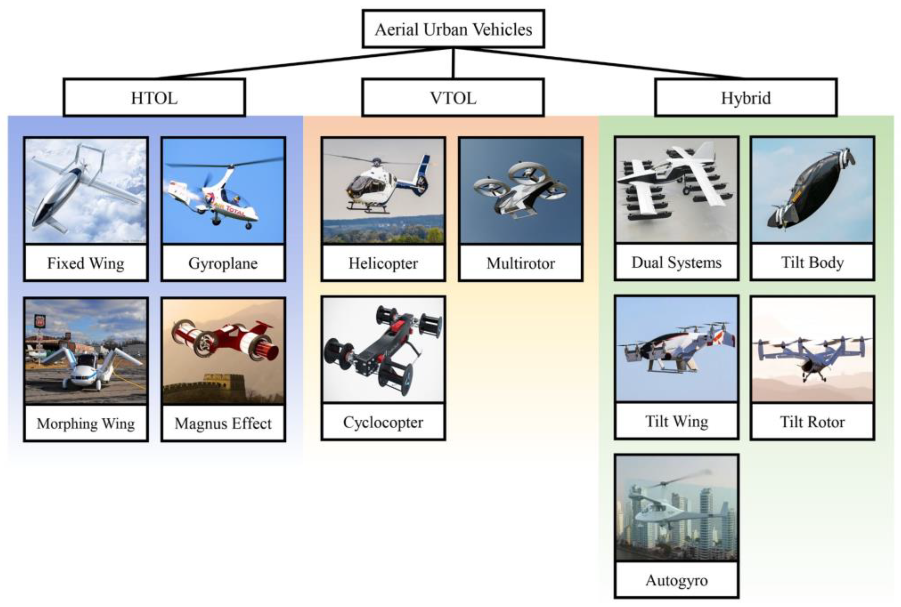


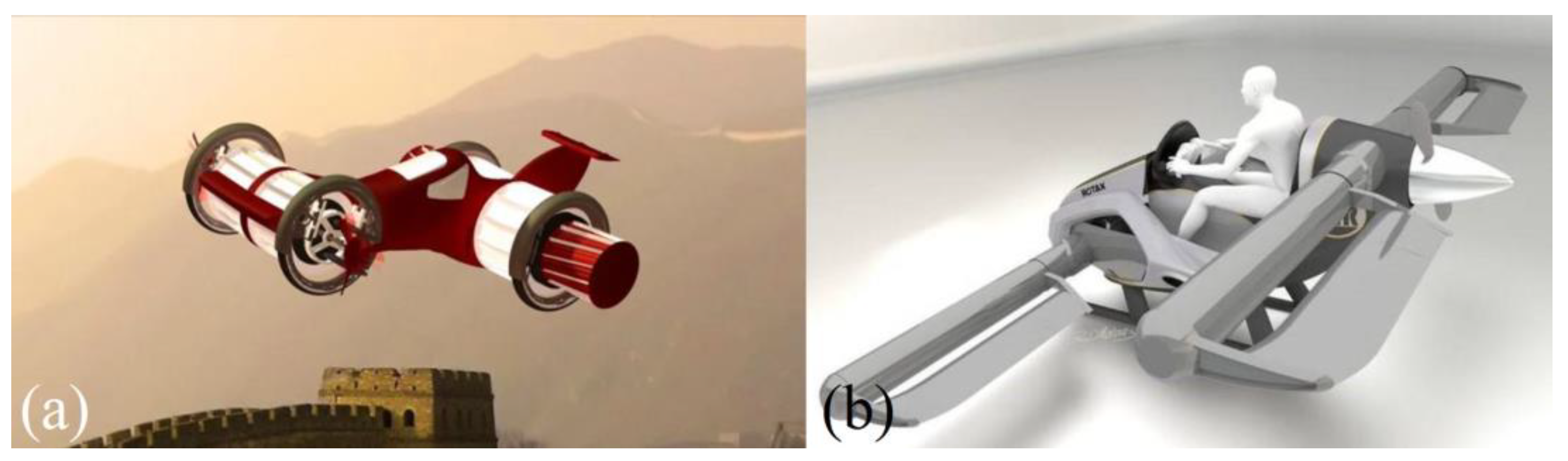


