1. Introduction
Recent advances in hardware and artificial intelligence (AI) systems have enabled the practical implementation of edge computing, facilitating real-time multi-view target tracking using multiple cameras. These systems hold significant potential for smart city applications, playing a vital role in scenarios such as real-time criminal tracking, efficient emergency traffic management, and military surveillance. By leveraging multi-view target tracking, such systems can provide comprehensive coverage, improve tracking accuracy, and enable seamless target handover across multiple cameras.
However, despite their potential, most existing multi-camera target tracking systems rely on centralized processing or computationally intensive models, making them unsuitable for real-time, resource-constrained applications (edge environments). These approaches often require transmitting raw or partially processed data to centralized servers, leading to latency, scalability issues, and data privacy concerns. Although some researchers have explored dynamic camera selection, they typically rely on reinforcement learning or heuristic-based approaches, which require extensive training and computational resources, making them impractical for on-device processing. Methods such as Q-learning and deep reinforcement learning-based camera selection [
1,
2] require large-scale training datasets and intensive computations, limiting their feasibility for lightweight edge-based implementations. Similarly, on-device tracking research has largely focused on single-camera setups, with minimal exploration of tracking across distributed camera networks. For example, Bewley A. et al.’s [
3] and Kalman E. et al.’s [
4] studies primarily addressed tracking within a single field of view, failing to tackle challenges such as multi-camera handover and target re-identification. Additionally, previous research has lacked a generalizable framework capable of adapting to varied tracking scenarios while maintaining efficiency and scalability in edge AI environments. These limitations highlight the need for a computationally efficient, scalable, and real-time framework for multi-camera tracking in distributed edge networks, which our work aims to address.
To address this gap, we propose the TEDDY framework, which stands for “An Efficient Framework for Target Tracking Using Edge-Based Distributed Smart Cameras with Dynamic Camera Selection”, an innovative and efficient solution for target tracking that leverages edge-based distributed smart cameras with context-aware dynamic camera selection. The key contributions of the TEDDY framework can be summarized as follows:
Energy-Efficient Multi-View Target Tracking for Resource-Constrained Environments: The TEDDY framework is designed to optimize power consumption in edge-based multi-camera tracking systems while ensuring accurate target tracking. By employing context-aware dynamic camera selection, it minimizes unnecessary computations and significantly reduces redundant processing, making it highly suitable for resource-limited settings.
Scalability and Flexibility for Large-Scale Deployments: The extensibility of the framework was demonstrated in the second experiment, where its application was expanded to a smart city scenario. The results highlight TEDDY’s ability to efficiently manage computational resources in large-scale multi-camera networks, ensuring energy savings while maintaining accurate tracking in real-world applications.
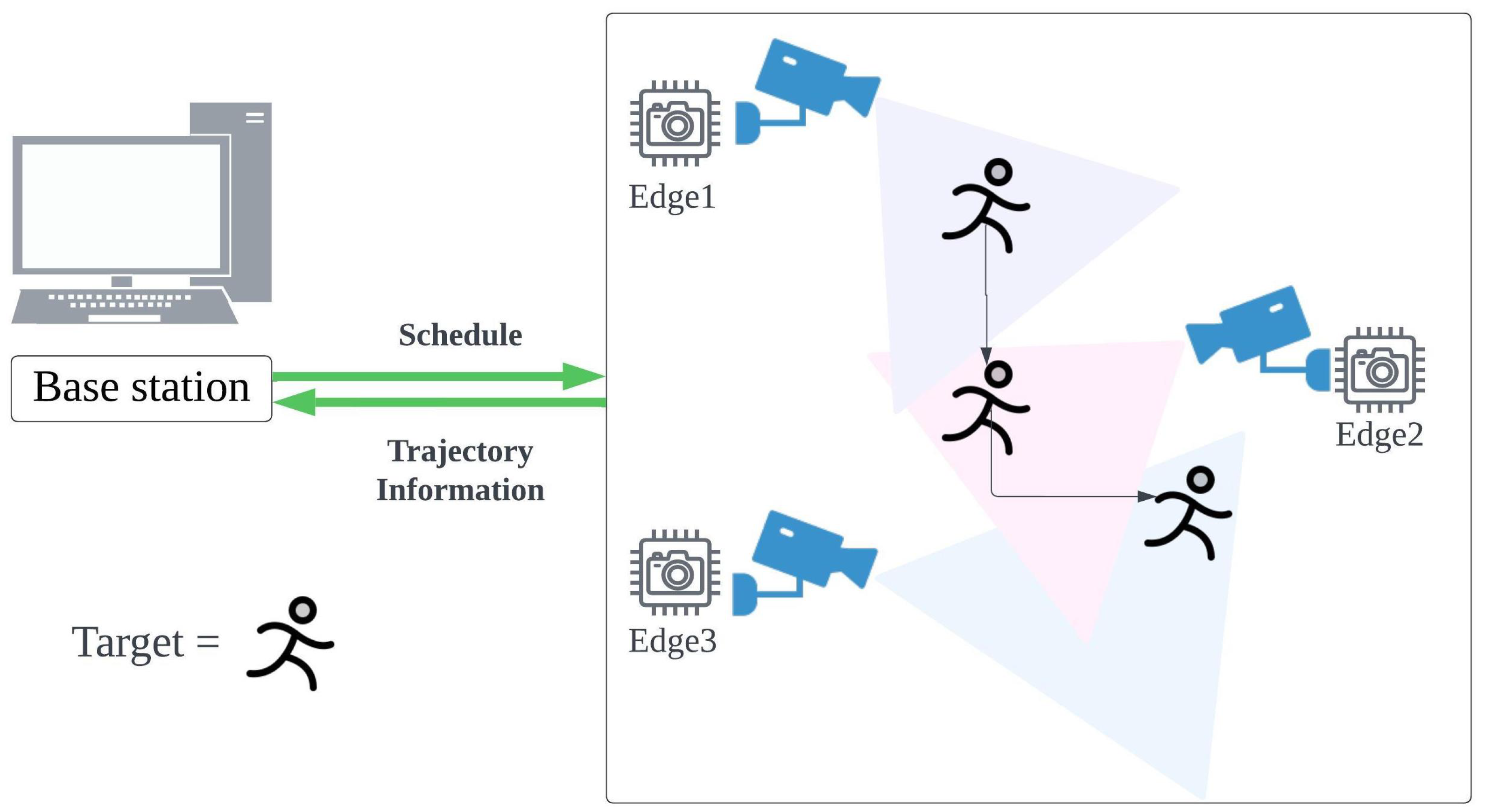
Figure 1 summarizes the proposed framework. The TEDDY framework operates through a network of distributed edge devices, each equipped with cameras or other sensors, strategically placed in the area where the target is expected to be. The central component of the system is the base station, which manages and coordinates the overall schedule of these edge devices.
In
Figure 1, the target is depicted as a person, and the system is shown with three edges. However, it is important to note that both the target and the number of edges are flexible and can vary, depending on the scenario.
To demonstrate the effectiveness of the TEDDY framework, we present two practical applications that validate its utility. First, we conducted an experiment with a single-person tracking system. For our first experiment, we designed a dataset simulating a scenario in which the system tracks a specific target—a person following various routes at different speeds. We compared our system, which employs dynamic camera selection, to a system without this feature. Our results demonstrate that our system achieves over 20% better performance, in terms of computational complexity and energy efficiency, when applied to embedded boards. In the second experiment, we simulated a smart city scenario, to test our method with a dynamic traffic light adjustment system as an extension of the scenario in the first experiment. Specifically, we modeled a city where traffic lights can adjust in real time when an emergency vehicle is detected, allowing it to reach its destination as quickly as possible. In this experiment, our framework reduced computations by around 90% compared to the always-on camera system, while achieving the same accuracy. As evident from the experiments, the novelty of our approach lies in its ability to dynamically optimize resource allocation in multi-camera tracking while maintaining high accuracy, demonstrating a scalable and energy-efficient solution for real-world applications.
The remainder of this paper is structured as follows:
Section 2 summarizes related work in the field of general camera tracking, camera selection, and on-device tracking.
Section 3 details the proposed TEDDY framework.
Section 4 presents our experimental setup and two distinct test scenarios, and
Section 5 shows the corresponding results.
Section 6 provides an in-depth discussion of the findings and addresses potential limitations of the framework. Finally,
Section 7 concludes the paper and discusses avenues for future research.
2. Related Works
2.1. Camera Tracking
Single-camera tracking serves as the basis for the more advanced tracking methods currently under investigation. It involves consistently identifying a moving target within the field of view of a single camera in consecutive frames. One of the pioneering works in this area was simple online and real-time tracking (SORT), proposed by Bewley et al. [
3], which leverages the fact that object movement between consecutive frames is typically small. The method uses a Kalman filter, introduced by Kalman [
4], to predict the spatial locations of tracklets, and it employs the Hungarian algorithm to associate these predictions with the current frame’s detections. Building on the SORT algorithm, Wojke et al. [
5] proposed DeepSORT, which enhances tracking by using a convolutional neural network (CNN) model for re-identification (Re-ID), to extract and match appearance features. Subsequent research continued to advance the use of appearance features, as demonstrated in the works of Wang et al. [
6], Zhang et al. [
7], and Yan et al. [
8]. Additionally, some approaches, such as those proposed by Braso et al. [
9], He et al. [
10], and Kim et al. [
11], have framed data association as a graph optimization problem. Multi-camera tracking (MCT) is a crucial area of research focused on monitoring targets across multiple camera views, as explored by Amosa et al. [
12]. Compared to single-camera tracking, which primarily aims to maintain the identity of a target within the field of view of a single camera, MCT poses additional challenges. These include managing varying camera viewpoints, addressing occlusions, synchronizing multiple camera feeds, and associating targets across non-overlapping camera views. Due to these varying viewpoints, complex Re-ID models are required to maintain target identity across different camera views, and the spatial relationships between multiple cameras must be carefully defined. Most of the recent research on multi-camera target tracking employs a two-step framework. First, single-camera tracking (SCT) is performed, followed by inter-camera tracking (ICT) using the information gathered from SCT. ICT approaches typically estimate entry–exit points between cameras, as demonstrated by Makris et al. [
13] and Cai et al. [
14], and they predict the future trajectory of the target, as explored by Styles et al. [
15] and Sharma et al. [
16]. Additionally, Re-ID methods are used to re-identify the target across different cameras [
17,
18,
19]. Graph-based approaches are also widely used to perform ICT [
20,
21,
22,
23,
24,
25]. Cai et al. [
14] leveraged spatiotemporal contextual information for tracking, while Ristani et al. [
26,
27] introduced clique-based approaches to enhance tracking performance.
2.2. Camera Selection in Tracking
Camera selection is a crucial aspect of multi-camera tracking systems. Processing data from all cameras simultaneously in a large-scale camera network can lead to inefficient computation. The goal of camera selection is to optimize resource utilization and tracking performance by selecting the camera where the target is most likely to appear next. Camera selection decisions can be addressed using various reinforcement learning methods. Sharma et al. [
1] employed a traditional Q-learning algorithm, to effectively solve the cross-camera handover problem and learn a selection policy. Sharma et al. [
2] also utilized deep Q-learning combined with n-step bootstrapping, to optimize the scheduling of re-identification queries in a multi-camera network. Additionally, Sharma et al. [
28] improved camera selection performance by leveraging state representation learning and adopting a semi-supervised learning approach to train the policy. These methods refine camera selection decisions and improve tracking efficiency.
Sequential characteristics can also be considered in tracking and camera selection. To handle these time-series characteristics, Styles et al. [
15] utilized deep learning models specialized for time-series data, such as long short-term memory (LSTM) and gated recurrent unit (GRU) models, to predict the next camera. They also explored methods such as the shortest distance, transition frequency, trajectory similarity with the training set, and handcrafted features for next-camera prediction.
2.3. On-Device Tracking
On-device tracking has gained significant attention as an efficient approach to real-time object tracking. Running tracking systems on a device is particularly valuable in environments where computational resources are limited, such as edge-based camera networks.
Various strategies have been developed, to reduce the computational overhead of on-device tracking from a single camera. Ganesh et al. [
29] proposed context-aware skipping techniques that dynamically skip certain video frames, reducing computational costs while maintaining tracking precision. In addition, Oh et al. [
30] introduced input slicing and output stitching methods, which partition high-resolution images for parallel processing and later recombine them, significantly reducing detection latency and improving tracking efficiency. Compared to the aforementioned methods, our approach offers significant advancements in both camera selection and on-device tracking. Prior studies on camera selection have often relied on reinforcement learning, which requires extensive training and is not optimized for on-device implementation, limiting its practicality in resource-constrained environments. In contrast, our framework eliminates the need for complex training processes, employing a simple yet effective method tailored specifically for on-device operation. Furthermore, while previous on-device tracking efforts have primarily focused on single-camera setups, very few have addressed the challenges of tracking across distributed cameras. Our framework bridges this gap by enabling seamless and energy-efficient tracking in distributed camera systems, providing a scalable and practical solution for real-world applications, particularly in resource-limited environments. This combination of simplicity, scalability, and on-device optimization highlights the novelty of our approach.
3. Proposed Method
The TEDDY framework is a novel, energy-efficient, and scalable approach to multi-camera target tracking that leverages dynamic scheduling and on-device processing. Unlike traditional systems that rely on the continuous operation of all cameras or complex reinforcement learning-based scheduling, the TEDDY framework dynamically activates and deactivates distributed edge devices based on the predicted trajectory of the target. This section details the architectural components, the iterative scheduling mechanism, the data flow, and the framework’s expandability, providing a comprehensive understanding of its design and functionality.
3.1. System Architecture
The TEDDY framework consists of two primary components: the base station and the distributed edge devices, as illustrated in
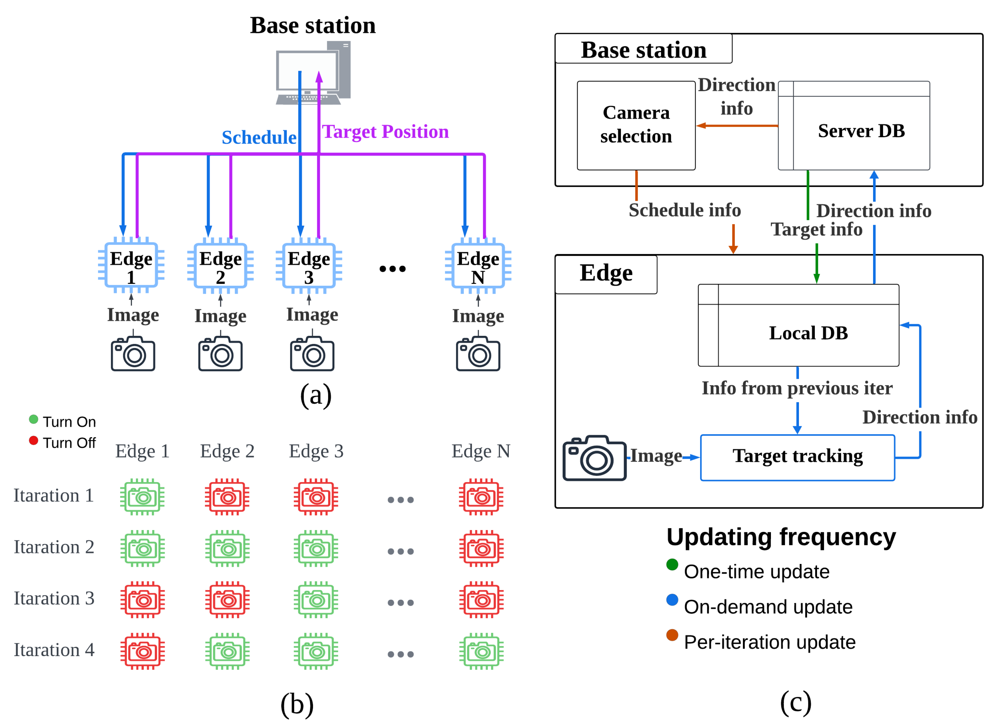
Figure 2a. The base station serves as the central control unit and is responsible for scheduling, coordination, and maintaining global tracking consistency. Edge devices are distributed across the system and perform localized target tracking using lightweight processing algorithms. The system operates in iterative cycles, with the base station and the edge devices collaborating to optimize tracking performance and resource efficiency.
At the beginning of each iteration, the base station evaluates the target’s predicted position and trajectory. Based on this evaluation, it determines which edge devices should be activated or deactivated during the upcoming cycle. The base station sends scheduling information to the selected edge devices and receives target position updates after each iteration. This division of labor ensures that computationally intensive tasks, such as trajectory prediction and scheduling, are handled by the base station, while the edge devices focus on localized, lightweight processing of image data. The edge devices are equipped with cameras and local databases that store the necessary tracking information for the current iteration. Unlike traditional systems that continuously upload raw data to a centralized server, the TEDDY framework processes data locally at the edge. This approach reduces bandwidth usage and energy consumption and enhances data privacy by minimizing the transmission of sensitive data.
3.2. Dynamic Scheduling
The dynamic scheduling mechanism is the core innovation of the TEDDY framework, as shown in
Figure 2b. Traditional camera networks often operate with all cameras active, resulting in unnecessary energy consumption and redundant processing. In contrast, the TEDDY framework optimizes resource utilization by activating only the edge devices that are relevant to the target’s current and predicted movement. The activation or deactivation of edge devices is determined by the presence of a target (see
Section 3.2.1) and dynamic selection by the base station (see
Section 3.2.2).
3.2.1. Activation and Deactivation Based on Target Presence
Before the system begins, the base station transmits target information, including a feature map of the target image, to the local database of each edge device. During the system initialization phase, edge devices are activated or deactivated based on whether a target is detected. Initially, the system activates all edge devices, to search for the target’s initial position. Once the target is detected, its feature map is transmitted to the base station, where a target ID is assigned and subsequently distributed to all edge devices. After this step, only the edge device where the target was first detected remains active, while all others are deactivated to conserve computational resources. Even during the tracking process, edge devices are deactivated based on the presence or absence of the target. If an active edge device fails to detect the target for a predefined number of frames, the system assumes that the target has moved to another edge device and deactivates the current edge device. At this time, the system analyzes the target’s previous trajectory data, to calculate its movement direction and transmits this information to the base station. This predefined number of frames is a tunable parameter set by the framework administrator, considering factors such as the occlusion rate and target speed.
3.2.2. Dynamic Selection by the Base Station
At the start of each iteration, the base station evaluates the target’s position, trajectory, and surrounding environmental factors, to determine which edge devices are most likely to capture the target’s movement in the next iteration. It then generates a schedule specifying which edge devices should remain active and which should be temporarily deactivated. This schedule is communicated to the edge devices before the iteration begins. The base station dynamically selects and activates edge devices based on the target’s expected trajectory. This activation–deactivation process continuously repeats throughout the tracking process, ensuring optimized resource allocation, reduced computational overhead, and efficient target tracking. The iterative scheduling process enables the system to adapt to dynamic scenarios, such as targets with unpredictable movement patterns or changing environmental conditions. By deactivating unnecessary edge devices, the TEDDY framework minimizes energy consumption while maintaining tracking accuracy. Furthermore, this iterative design allows the framework to scale efficiently, as additional edge devices can be integrated into the network without overwhelming the system.
3.3. Dataflow and Communication
As illustrated in
Figure 2c, the data flow and communication between the base station and edge devices are designed to balance efficiency, accuracy, and scalability. The base station plays a central role in the system, predicting the target’s trajectory based on previous position data and movement patterns, generating optimal schedules for activating and deactivating edge devices, and maintaining a centralized server database that stores information, such as the target’s position, movement direction, and scheduling updates. On the other hand, the edge devices perform localized processing of image data, to detect the target and analyze its movement direction, thereby reducing the computational load on the base station and minimizing data transmission requirements. Each edge device maintains a local database, to store relevant tracking information, and it sends processed updates, including the target’s position and direction, back to the base station. Communication between the base station and edge devices follows a structured approach with three types of updates: one-time updates for initial settings, on-demand updates to dynamically control the schedule of the edge devices, and per-iteration updates, which include real-time tracking results sent at the end of each iteration, to ensure synchronization and accuracy. This structured data flow reduces communication overhead while maintaining the system’s responsiveness and accuracy in dynamic and resource-constrained environments. To ensure data consistency, the base station serves as the authoritative node for tracking metadata. When an edge device updates a re-identification feature, it sends these lightweight data to the base station, which then broadcasts the update to all active devices. This approach ensures that all devices share the same target identifiers.
Furthermore, if an edge device loses connectivity, it continues to track locally and accumulates new detections and feature updates. Once connectivity is restored, these stored updates are transmitted to the base station and merged into the global tracking state during the next scheduling cycle. This mechanism maintains tracking consistency despite short-term network disruptions.
4. Experimental Settings
To evaluate the effectiveness of our TEDDY framework, we conducted two distinct experiments. The first experiment focused on tracking a person across multiple cameras in an indoor environment. The second experiment involved a smart city simulation, where we implemented a dynamic traffic light adjustment system to prioritize the movement of an emergency vehicle. In both experiments, we compared the performance of systems with and without the TEDDY framework, to assess its impact. Furthermore, the second experiment demonstrated the framework’s flexibility and ability to seamlessly adapt to other applications.
4.1. Algorithms
4.1.1. Target Object Detection
To detect a target object in real time, we utilized the You Only Look Once version 8 (YOLOv8) model, which offers both high accuracy and rapid processing, making it well suited for real-time tracking on edge devices [
31]. YOLOv8 is available in various model sizes (n, s, m, l, xl), enabling flexibility based on resource constraints and performance requirements. For our experiments, we employed the lightweight YOLOv8n model, to balance computational efficiency and detection accuracy. We chose YOLOv8n primarily because it is widely recognized as a highly efficient and lightweight model, offering a strong balance between detection accuracy and real-time performance on resource-constrained devices. Its straightforward fine-tuning process and reliable empirical performance make it especially well suited for our edge-based tracking framework, where both speed and accuracy are crucial. YOLOv8n has the fewest parameters and the lowest computational load, still ensuring smooth operation on edge devices with limited resources. For both experiments, the pre-trained YOLOv8n [
31] model was fine-tuned using additional data tailored to the experimental environment. This fine-tuning process enhanced the detection performance for specific objects, such as people and emergency vehicles, thereby improving the accuracy of target detection.
4.1.2. Re-ID and Target Tracking
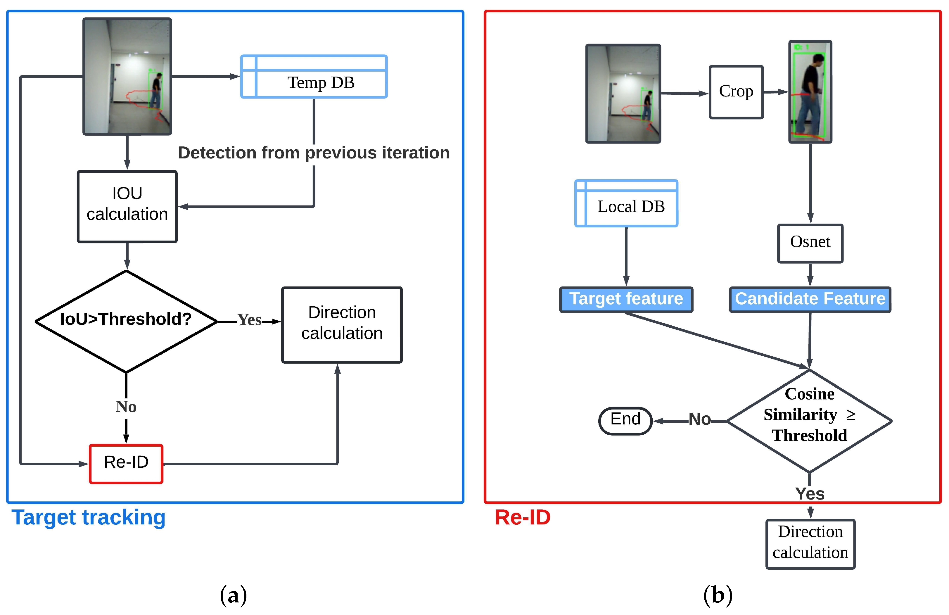
As illustrated in
Figure 3a, the process began with the calculation of the intersection over union (IoU) between the detection result from the current iteration and that from the previous iteration. The IoU value served as a measure of overlap between the two detections. If the IoU exceeded a predefined threshold, which was a hyperparameter tuned during the experiment, the framework assumed that the detected object was the same target from the previous iteration. We tuned this threshold by testing values from
to
in
increments on a small validation subset. Thresholds at or below
led to increased false associations, while thresholds at or above
resulted in more missed associations. An IoU threshold of
provided the best balance, ensuring stable object associations while minimizing unnecessary Re-ID computations. In this case, it directly proceeded to the direction calculation process, bypassing additional verification steps. However, if the IoU did not exceed the threshold, the system initiated the Re-ID process, to confirm whether the detected object matched the target, as detailed in
Figure 3b.
In the Re-ID process, the detected individual was cropped from the image, and the feature map of the detected area was extracted using the Omni-Scale Network (OSNet). Specifically, we utilized the OSNet x1.0 model from the TorchReID library [
32,
33,
34], which offered superior performance relative to the other available models in the library. OSNet is particularly well suited for edge device implementations, due to its efficiency, as it has 2-to-10-times fewer parameters compared to models such as ResNet or MobileNet, making it significantly more lightweight. However, while OSNet is highly optimized for person re-identification, it may not generalize as well to more diverse image domains. In contrast, larger models, such as ResNet, often provide higher accuracy and robustness across varied tasks, though at the cost of increased computational and memory demands. This trade-off made OSNet an efficient choice for our resource-constrained edge devices, despite some limitations in absolute performance and adaptability.
After feature extraction, the system computed the cosine similarity (defined as the normalized dot product of two vectors that measures the cosine of the angle between them) between the candidate feature map (obtained from the current detection) and the target feature map stored in the local database. This metric quantified the degree of directional alignment between the two feature vectors, meaning it assessed how similarly the image features were oriented. In practical terms, the directional alignment of the image feature vectors indicated how well the underlying visual patterns matched. If two images contained the same object, their feature vectors tended to be closely aligned, resulting in a higher cosine similarity value. If the computed cosine similarity exceeded a predefined threshold (a tunable hyperparameter), the framework determined that the detected object matched the target, and it proceeded to the direction calculation process. Conversely, if the similarity fell below the threshold, the process terminated without further actions. Through experimentation, we observed that setting the cosine similarity threshold below 0.5 often led to incorrect ID assignments, where different objects were mistakenly assigned the same identity. Conversely, setting the threshold above 0.8 caused inconsistency in re-identification, due to variations in lighting conditions, resulting in failure to assign a consistent ID even to the same object. To balance these trade-offs, we selected an optimal similarity threshold based on empirical results. Similarly, following the same approach as for the IoU and cosine similarity thresholds, we tuned the threshold by testing values from 0.3 to 0.9 in 0.1 increments on a small validation subset. In Experiment 1, we applied a Re-ID threshold of 0.6, while in Experiment 2 we used a Re-ID threshold of 0.7. This demonstrated that the threshold can be appropriately adjusted, depending on the deployment environment.
Additionally, when an object was first detected, the Re-ID procedure was performed, to determine whether the detected object was the actual target. In this process, the features of the detected object, obtained by cropping the relevant image, were extracted using the Re-ID model. These feature vectors were then sent to the server, allowing all the edge devices in the network to share consistent target information. This ensured that the tracking process remained unified and accurate across the distributed devices. If the target object was known beforehand, its feature vectors could be precomputed and distributed to edge devices through the server, bypassing the need for on-the-fly feature extraction during the first detection. To maintain clarity and avoid overcomplicating the visualization, the details of this specific case have been omitted from
Figure 3. This approach ensured that the framework remained flexible, accommodating both scenarios where the target was predefined and where it needed to be identified dynamically.
4.1.3. Camera Selection
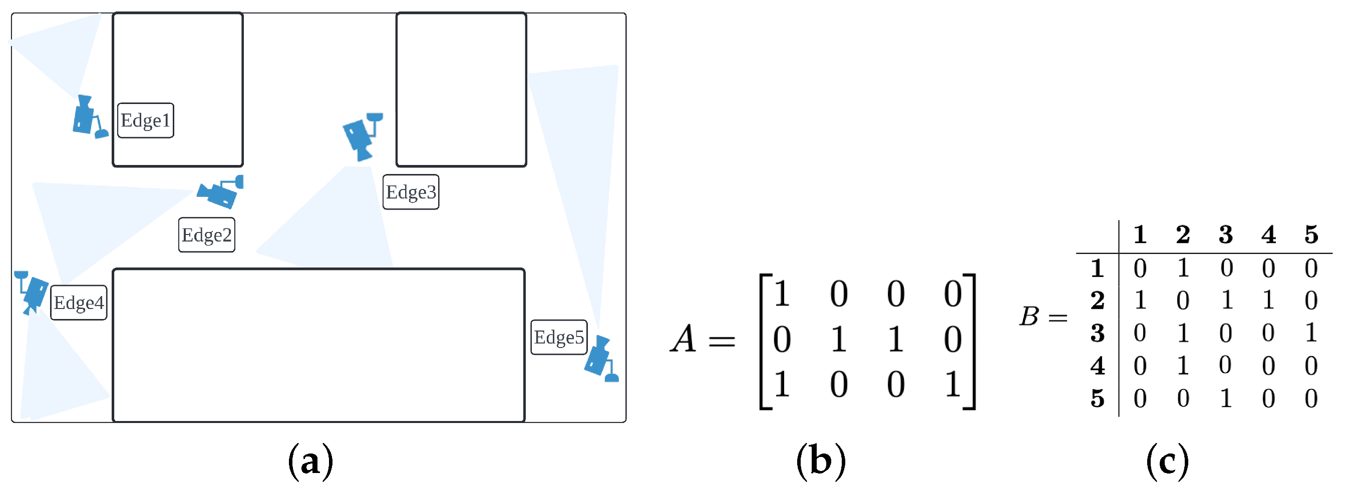
The camera selection process was deployed to activate edge devices based on the movement of a tracked target. To implement camera selection, the spatial relationships of the camera network were first represented using matrices. The network was visualized from the top view, and each camera location was marked as “1” on an
matrix, to create the first matrix,
A. This matrix visually represented the camera layout within the network. The second matrix,
B, was an adjacency matrix that expressed how the cameras were interconnected (see
Figure 4c). Camera numbers were assigned sequentially from the top-left to the bottom-right corner of matrix
A, and these numbers were used as indices in matrix
B to organize the connectivity information. An example of the camera network and the method for assigning indices can be seen in
Figure 4a,b.
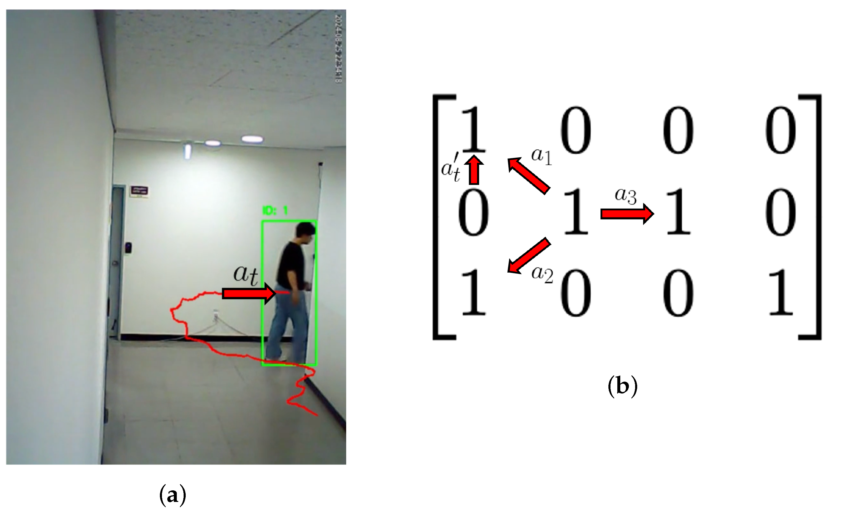
Camera selection was performed by utilizing directional vectors between nodes in matrix A. For example, when a target moved from the area covered by Camera 2 to the area covered by Camera 1, the directional vector from Camera 2 to Camera 1 was computed based on matrix A. Normalizing this vector to a magnitude of 1 yielded a directional vector, , of . Similarly, all directional vectors from Camera 2 to its connected nodes (e.g., Cameras 1, 4, and 3) were calculated. For example, the directional vector from Camera 2 to Camera 4, , was , and the vector from Camera 2 to Camera 3, , was . These vectors represented the spatial relationships between the nodes.
Next, the actual movement direction of the target was compared with the directional vectors between the camera nodes, to determine the next camera. When a target moved within the view of Camera 2, the average movement direction over the last five frames was calculated, to obtain
. This process is visually confirmed in
Figure 5a. Since the camera views differed in orientation,
was rotated to align with the camera’s perspective and normalized to produce
. This normalized vector,
, represented the target’s movement direction in the camera network, considering the camera’s orientation.
Subsequently, the cosine similarity (defined as the normalized dot product of two vectors that measures the cosine of the angle between them) was calculated between
and the directional vectors
,
, and
derived for Camera 2. In physical terms, this metric quantified how well the target’s movement direction (represented by
aligned with the candidate camera directions. In other words, it evaluated which camera’s orientation best matched the predicted trajectory of the target. For instance, given an initial movement vector
the directional vectors of the connected cameras were defined as follows:
The cosine similarity between
and each directional vector was then computed:
As depicted in
Figure 5b,
and the directional vectors
,
, and
represented in matrix
A could be intuitively visualized. The edge corresponding to the vector with the highest cosine similarity was activated to select the next camera, which in this case was Edge 1 corresponding to
. This process dynamically tracked the target and ensured that the most appropriate camera was activated at each step. Through this methodology, camera selection was effectively implemented within the camera network.
The experiments were conducted using a self-collected dataset comprising footage from five strategically positioned cameras, as outlined in
Table 1a,b. These cameras were installed at key locations within the experimental environment, to ensure optimal coverage of the target object as it navigated through multiple predefined routes.
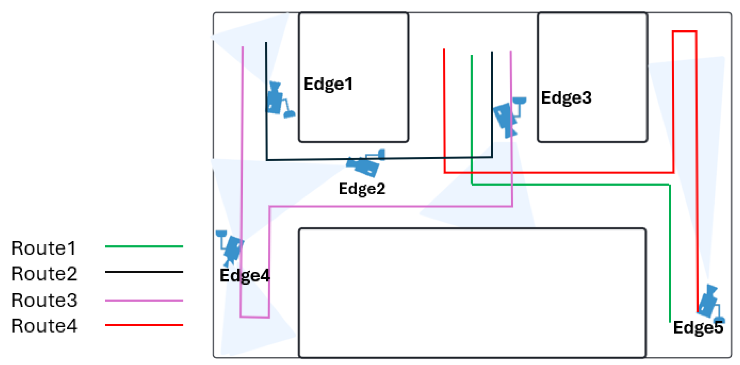
Figure 6 illustrates the layout of these routes and the placement of the cameras, which were designed to simulate realistic scenarios involving various behavioral patterns.
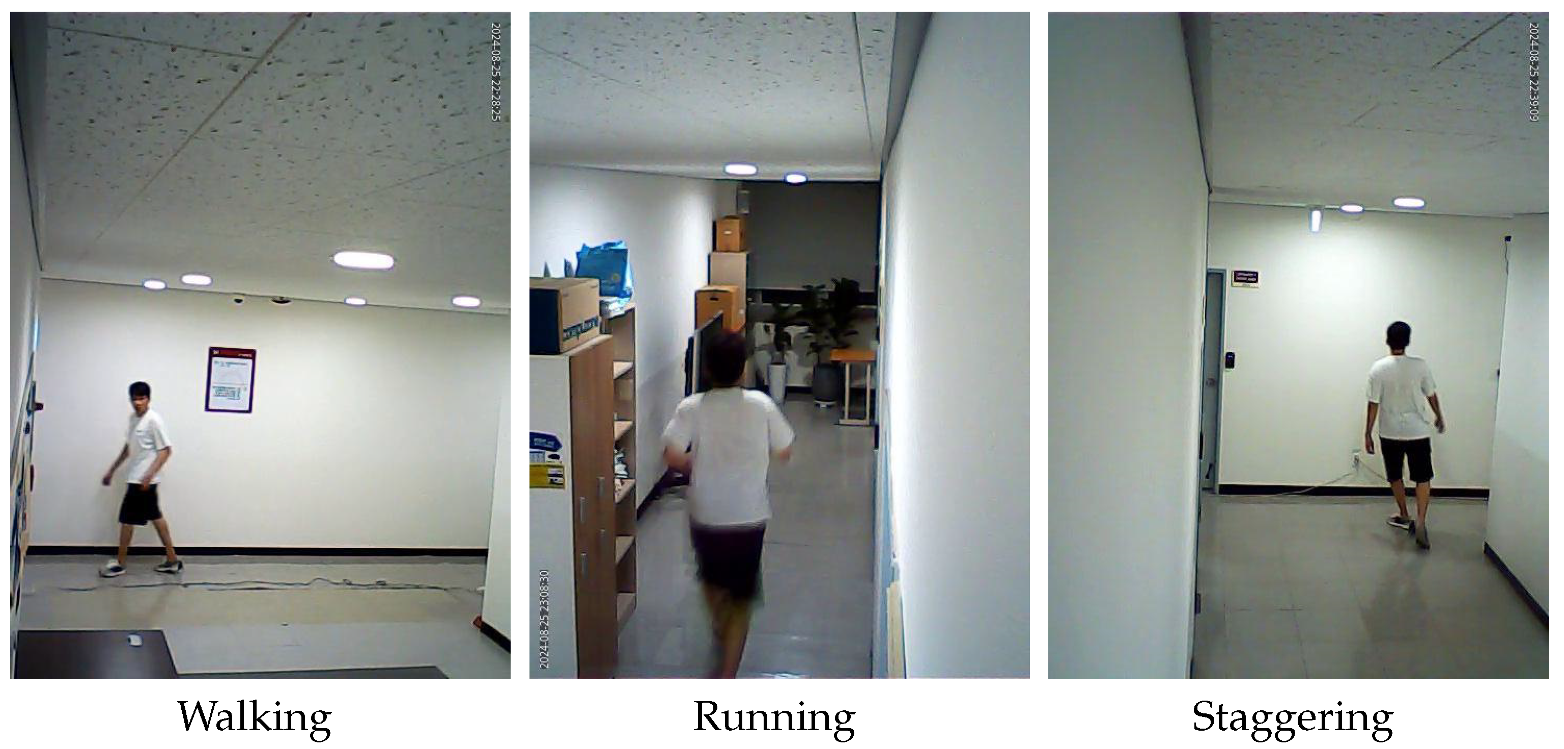
Each route in the dataset was specifically designed to encompass three types of target behaviors: walking, running, and staggering. The walking behavior represented a consistent and steady movement, reflecting the most common and predictable gait pattern observed in pedestrian monitoring. The running behavior involved rapid movement, which presented a greater challenge for accurate tracking, due to increased speed and shorter intervals between camera transitions. The staggering behavior introduced irregular and unpredictable movement patterns, characterized by abrupt changes in direction and unstable trajectories, further testing the system’s robustness. These three behaviors were selected based on their relevance to real-world surveillance applications. Walking is frequently analyzed in pedestrian tracking, while running is often associated with suspicious activities, emergency responses, or law enforcement scenarios, making it a crucial behavior for monitoring systems. Staggering is particularly significant in health monitoring, anomaly detection, and security surveillance, where identifying erratic behavior can be essential for intervention. By incorporating these distinct movement patterns, the TEDDY framework was evaluated across diverse tracking conditions, demonstrating its adaptability to various real-world scenarios. The dataset included a comprehensive collection of frames for each route and behavior type, providing sufficient diversity for experimental analysis. The detailed frame counts for each route and behavior type are presented in
Table 1b. Additionally,
Figure 7 showcases illustrative examples of each behavior type along the various routes, offering visual insight into the complexity and variety of the scenarios captured in the dataset. This well-structured and diverse dataset forms the basis for evaluating the performance of the TEDDY framework in dynamic and challenging environments.
4.1.4. Experiment 2: A Traffic Light Adjustment System for an Emergency Vehicle
The purpose of Experiment 2 was to demonstrate the versatility of the TEDDY framework beyond a simple tracking system, through its application to emergency vehicles, and to validate the computational efficiency by utilizing the TEDDY framework.
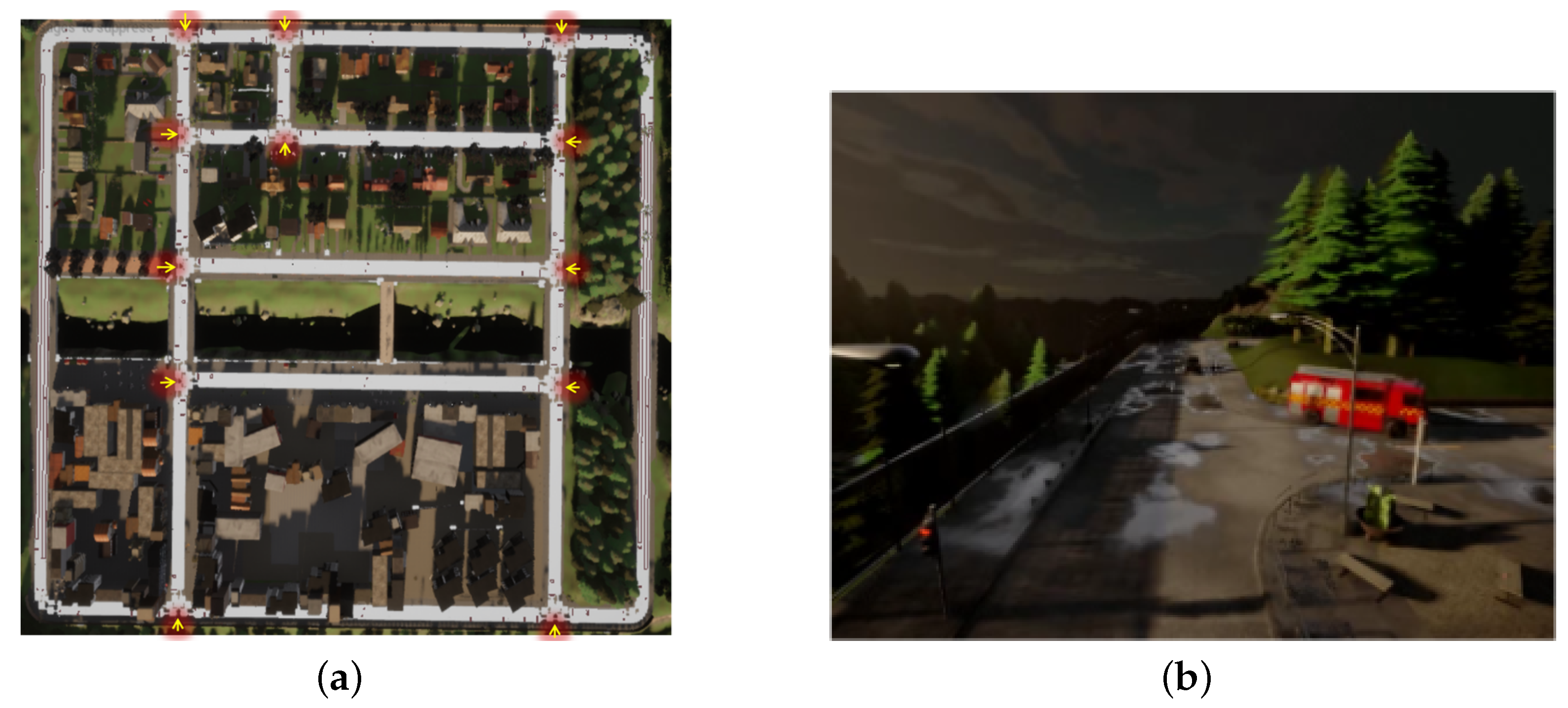
The scenario used in Experiment 2 was an urban environment in which an emergency vehicle drove along with other vehicles. In Experiment 2, the TEDDY framework targeted the emergency vehicle for tracking. The experimental environment was set up in Unreal Engine using CARLA [
35], which is widely used in research to simulate environments similar to the real world. The environment consisted of a rectangular urban area with various vehicles driving while following traffic signals. The CARLA 4.26 Python application programming interface (API) was used to create this environment. A total of 12 closed-circuit televisions (CCTVs) were set up in the experimental environment and placed at locations where vehicles within the environment might change direction.
Figure 8a shows the simulation environment viewed from above, and (b) depicts a scene with the emergency vehicle navigating through the actual simulation setting.
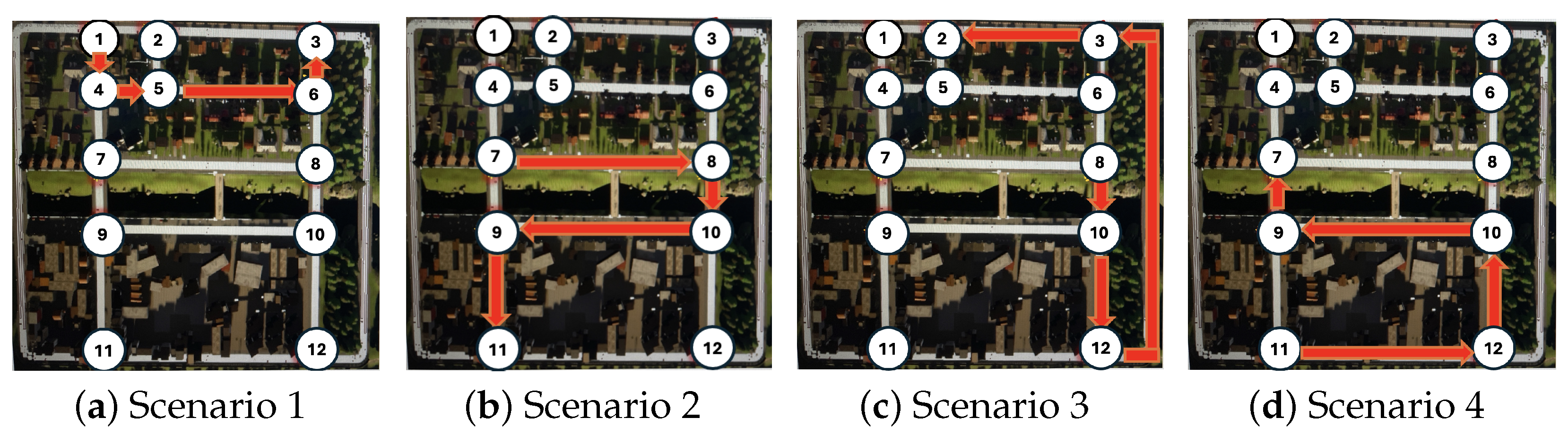
Figure 9 illustrates the four predefined paths used in the experiment, with the movement of the emergency vehicle indicated by red arrows. Each scenario was randomly selected within the CARLA simulation environment, providing diverse and realistic testing conditions. The white circles with sequential numbers represent the locations of the surveillance cameras, numbered from the top-left to the bottom-right of the map. Each surveillance camera was strategically positioned to monitor multiple paths, covering the front, left, and right directions. For instance, Camera 5 was oriented to provide a viewpoint toward Camera 2, ensuring comprehensive coverage along the vehicle’s route.
4.1.5. Implementation Details
In Experiment 1, five Raspberry Pi 5 devices were used as edge devices, each running Ubuntu 24.04 as the operating system (OS) and equipped with 8 GB of RAM. They were chosen for their balance of processing power, energy efficiency, and cost-effectiveness. This setup provided sufficient spatial coverage to track the target’s movements while reflecting real-world resource constraints. Although additional edge devices could improve scalability and resolution, our results show that even this limited configuration effectively demonstrates the framework’s performance. These devices were responsible for performing local computations as part of the TEDDY framework.
A computer with an AMD Ryzen 5 5600HS processor and 16 GB of RAM served as the base station, acting as the central decision-making unit for camera scheduling and target trajectory predictions. The base station also operated on Ubuntu 24.04, to ensure compatibility across the system. The video recordings used in the experiment were captured using cameras with a maximum resolution of 640 × 480 pixels, ensuring consistent video quality across all edge devices. To accurately measure power consumption, a Beezap Type-C Voltage Current Tester was utilized. This setup provided a controlled environment, to evaluate the TEDDY framework’s performance, in terms of computational efficiency, power consumption, and tracking accuracy while highlighting its suitability for resource-constrained edge hardware configurations. Moreover, to minimize external threats and safeguard sensitive information, the system was deployed on a dedicated, non-internet-facing network. This closed communication environment substantially mitigated common internet-based attacks by ensuring that no direct external route into the network was available.
In Experiment 2, evaluations were conducted on hardware equipped with a 12th Gen Intel i7-12800HX processor and an NVIDIA 3080 Ti GPU with 16 GB VRAM and running Linux 22.04 LTS. Since the evaluation was conducted on a single hardware platform, it was assumed that the camera would be activated 1-to-3 frames later, proportional to the time required for camera selection and communication between the base station and the edge devices. The experiment involved four scenarios with varying frame counts: Scenarios 1, 2, 3, and 4 included 1267 frames, 1706 frames, 1565 frames, and 1491 frames, respectively. These scenarios were designed to test the TEDDY framework’s performance in handling dynamic tracking tasks within diverse and realistic settings.
5. Results
5.1. Experiment 1: Single-Person Tracking
In the first experiment, we evaluated the TEDDY framework by comparing its performance to a multi-camera target tracking system, where all cameras remain continuously active. In the TEDDY framework, cameras located at entry points operate continuously, to ensure that no individual entering or exiting the building is missed. Once a target is detected, the framework dynamically activates only the cameras expected to capture the target, based on its movement and predicted trajectory. The remaining cameras are deactivated, significantly reducing unnecessary operations and improving resource efficiency. In contrast, the always-active camera method processes data from all cameras continuously, regardless of the target’s position. While this ensures comprehensive coverage, it results in substantially higher resource consumption and computational load, due to the constant activity of all the cameras. By dynamically managing camera activation, the TEDDY framework demonstrates a more efficient approach to resource allocation while maintaining accurate tracking capabilities. Both methods were tested using the same dataset and under identical conditions, to compare their outcomes. In each experiment, power consumption and tracking performance were measured, to evaluate the efficiency of the TEDDY framework.
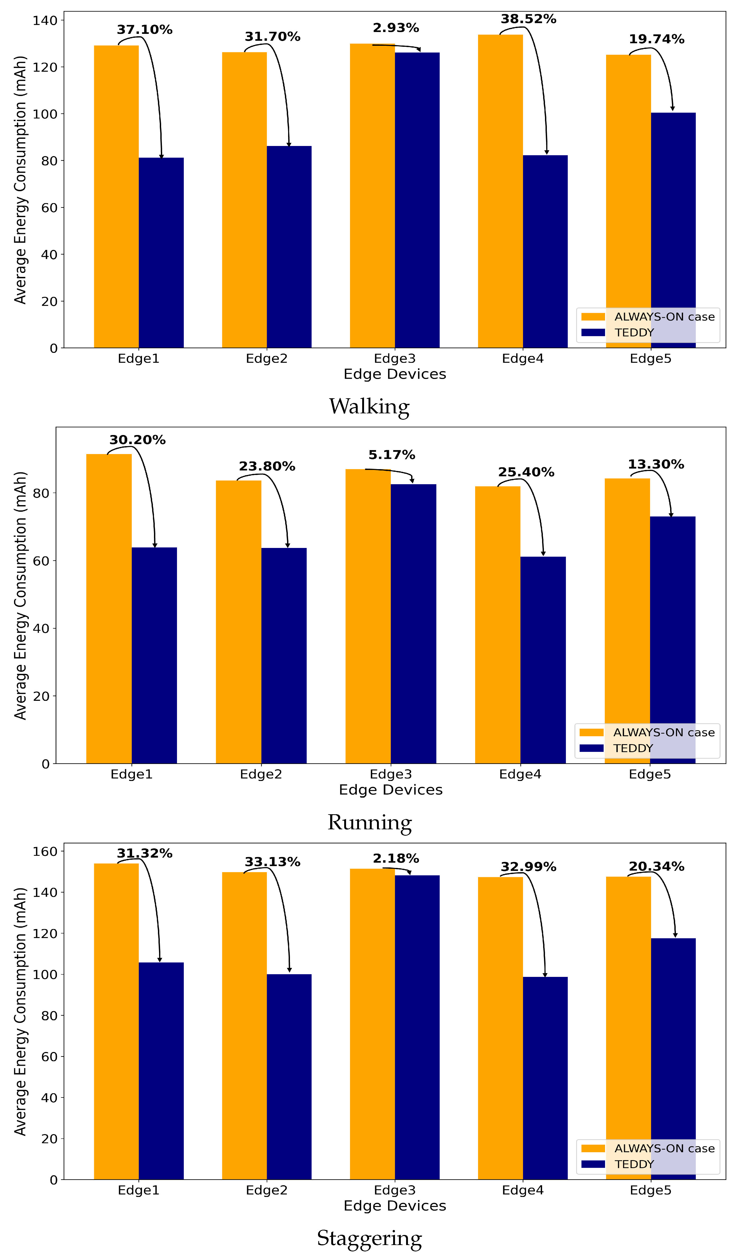
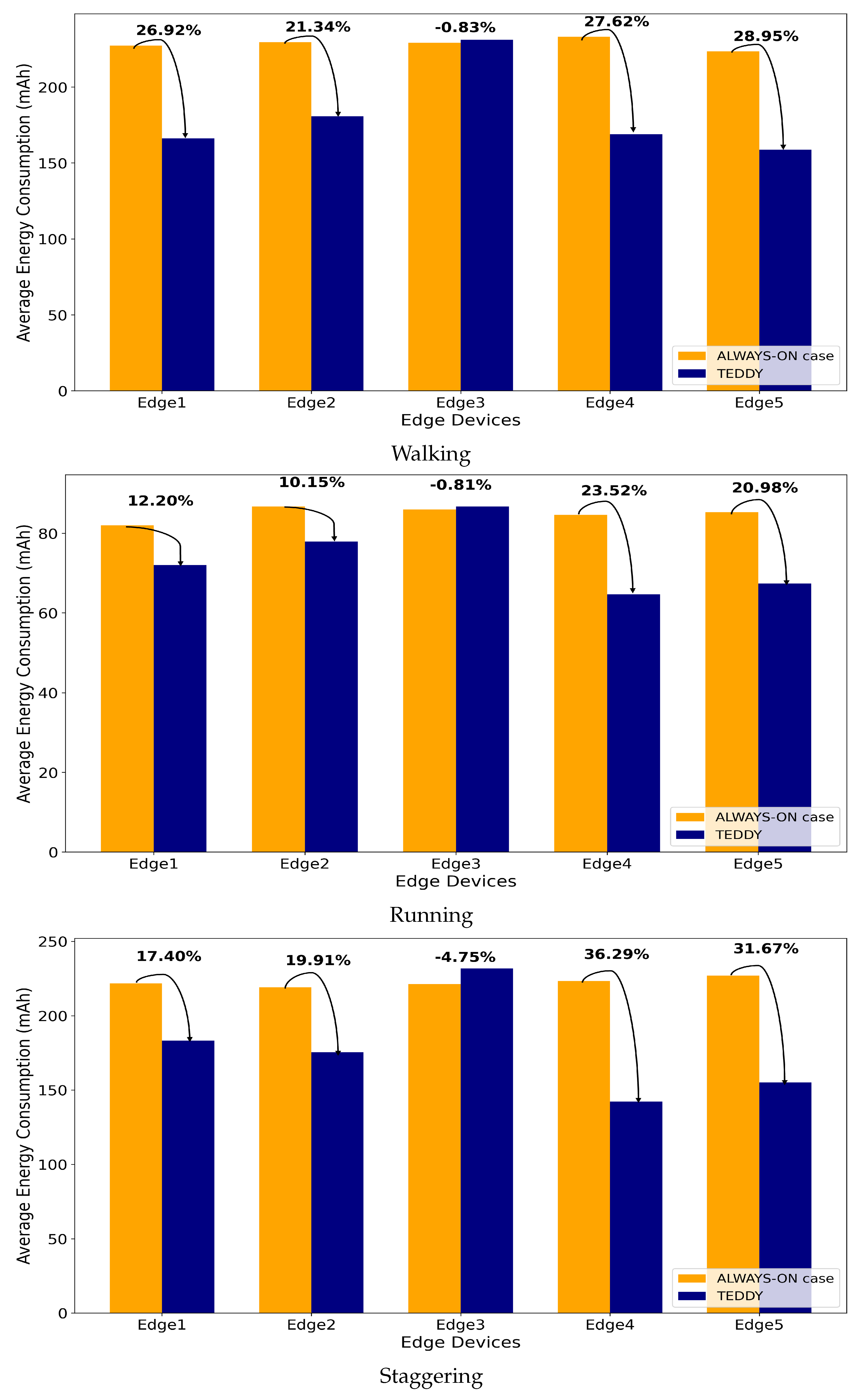
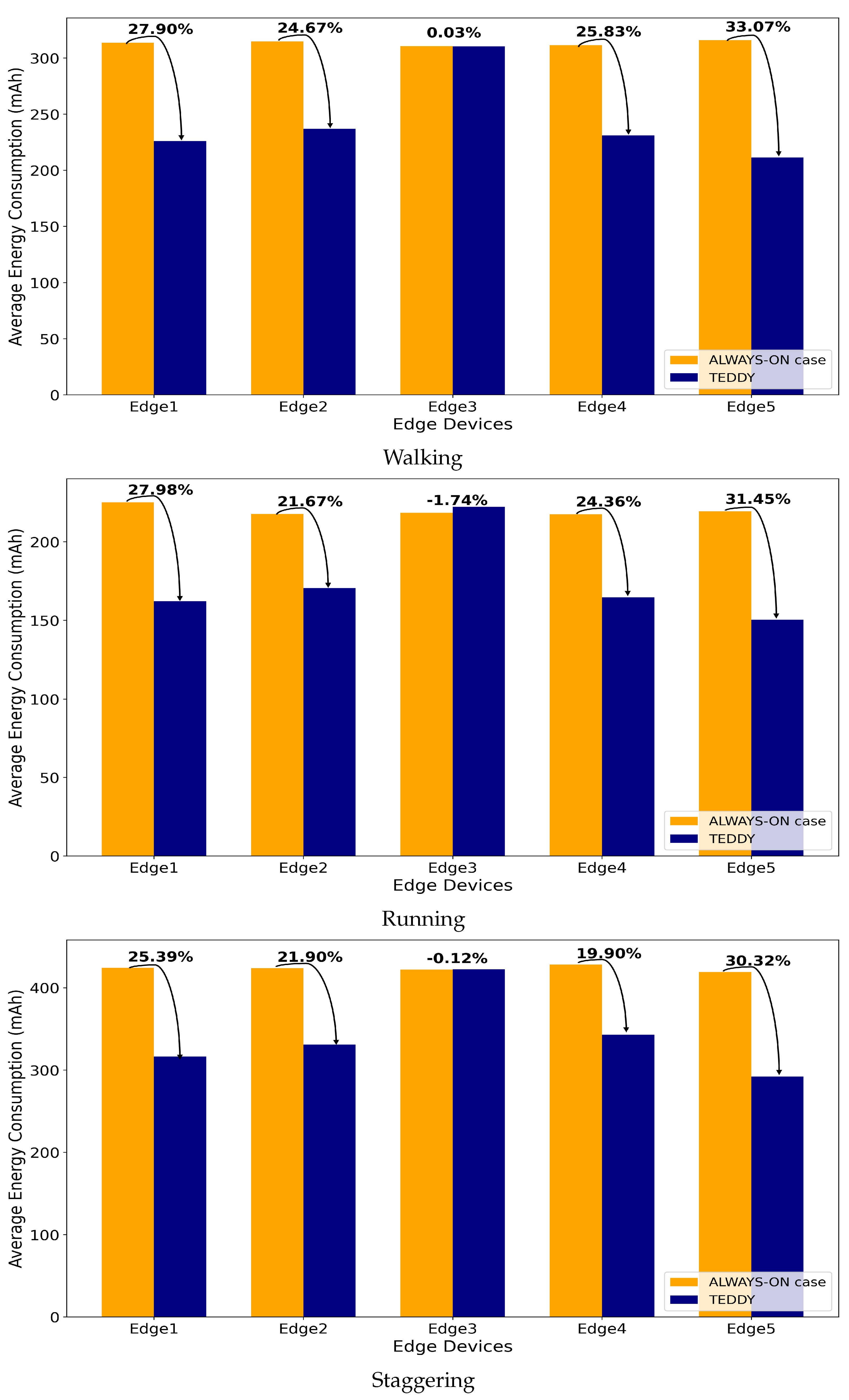
The experimental results shown in
Figure 10,
Figure 11,
Figure 12 and
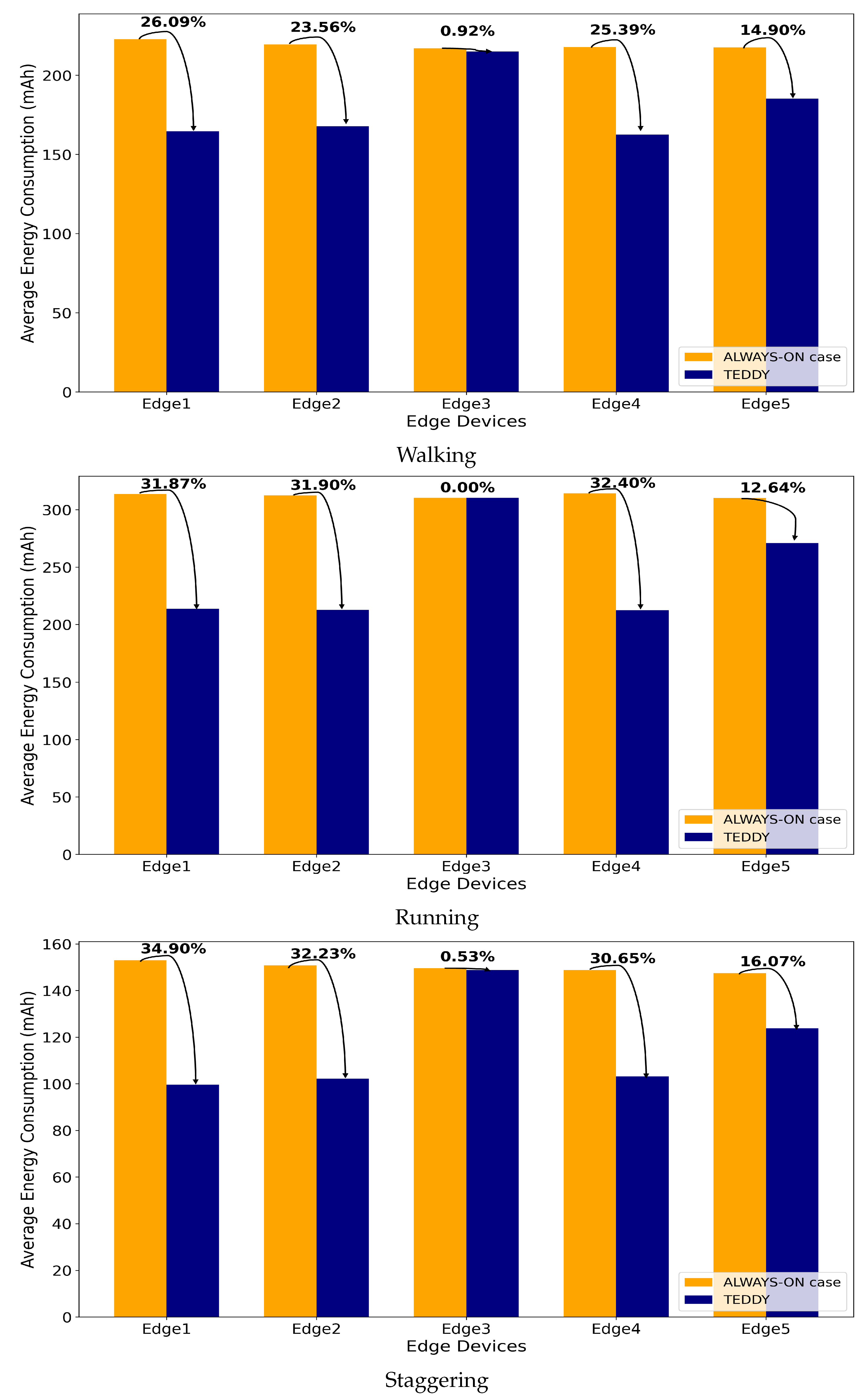
Figure 13 provide a detailed analysis of power consumption and efficiency across various routes and behavior types. The results clearly demonstrate that the TEDDY framework significantly reduces energy usage compared to the traditional method, where all cameras remain continuously active. Specifically, the TEDDY framework achieved a 20.96% reduction in power consumption, highlighting the effectiveness of its dynamic camera selection mechanism. This reduction was a direct result of the framework’s ability to deactivate unnecessary cameras and ensure that only the cameras relevant to the target’s trajectory remained active, thus enhancing overall resource efficiency. To further evaluate consistency, we performed ten repeated trials for each route and behavior type, measuring the power consumption (in mAh) of each edge device.
Table 2 presents the means and standard deviations of these trials for Routes 1–4 with the TEDDY framework activated. Each group corresponded to a set of scenarios covering different movement behaviors (walking, running, and staggering). The average indicates the typical power draw under each condition, whereas the standard deviation quantifies how consistently the system performed across repeated runs. Lower standard deviations suggest more stable energy usage, whereas higher values indicate greater variability.
In addition to power savings, the TEDDY framework was evaluated for its tracking accuracy in comparison to the always-active camera approach. The findings indicate that both methods achieved identical performance, in terms of maintaining consistent and reliable tracking until the completion of the target’s trajectory. This demonstrates that the TEDDY framework achieves significant energy efficiency without compromising the tracking performance. The ability of the TEDDY framework to effectively balance energy optimization and operational accuracy validates its potential as a robust and practical solution for multi-camera tracking systems in resource-constrained environments. The results reaffirm that the framework successfully optimizes energy usage while preserving high tracking effectiveness across diverse scenarios.
5.2. Experiment 2: A Traffic Light Adjustment System for an Emergency Vehicle
In Experiment 2, the TEDDY framework was evaluated by comparing its computational efficiency to that of a traditional always-on camera system, similar to the analysis conducted in the previous experiment. To facilitate this comparison, the TEDDY framework, comprising 12 edge devices and a base station, was implemented on a single hardware platform. This setup allowed for a direct performance comparison, demonstrating the advantages of the dynamic scheduling mechanism in reducing unnecessary computations while maintaining high operational effectiveness. The results validate the TEDDY framework’s ability to optimize computational resources, particularly in scenarios requiring efficient and responsive tracking, such as emergency vehicle management.
In this experiment, we aimed to demonstrate the potential applicability of the TEDDY framework in controlling traffic light systems, particularly in scenarios involving emergency vehicles. While the framework was evaluated for its ability to optimize camera usage and computational efficiency, building and integrating a complete traffic light control system was beyond the scope of this study. Therefore, we focused on simulating the target-tracking and trajectory-prediction capabilities of the framework, which are fundamental components for implementing such traffic control applications. This approach highlighted the framework’s potential for future extensions to real-world traffic management systems without compromising the primary focus of this work. In each scenario, we measured the number of processed frames and the computational load for both the always-on camera system and our TEDDY framework, concentrating exclusively on computations related to the tracking task.
This focused evaluation ensured a direct comparison of the framework’s efficiency in handling tracking operations under identical conditions. The results revealed the advantages of the TEDDY framework in minimizing computational overhead while maintaining tracking accuracy, demonstrating its ability to optimize resource utilization compared to the always-on approach. The detailed results are presented in the subsequent sections, to illustrate these performance improvements.
Table 3 summarizes the experimental results, demonstrating the significant computational load reduction achieved by the TEDDY framework compared to the always-on system. By limiting inference to the edge devices where the target is present, the TEDDY framework minimized unnecessary computations and optimized resource utilization.
Table 2 shows that the always-on approach continuously activated all 12 cameras, to perform inference for tracking. This means that every camera processed every frame throughout the entire scenario. In contrast, the TEDDY framework activated only the cameras most likely to detect the target, significantly reducing unnecessary computations. The Total Frame represents the total number of frames (or time steps of a scenario) from the start to the end of the scenario. In the always-on approach, all 12 cameras performed inference on every Total Frame simultaneously. Conversely, the TEDDY framework dynamically selected cameras based on the target’s predicted path, ensuring that only the selected edge devices performed inference.
As shown in
Table 3, the number of processed frames decreased substantially across all scenarios. For instance, in Scenario 2 (tracking a firetruck along the route monitored by Cameras 7, 8, 10, 9, and 11), the always-on system performed inference on all 12 edge devices, processing a total of 20,472 frames. In contrast, the TEDDY framework only processed 1697 frames, distributed among Cameras 7 (127 frames), 8 (464 frames), 10 (150 frames), 9 (625 frames), and 11 (331 frames). This substantial reduction in processed frames demonstrates the effectiveness of the TEDDY framework in optimizing computational efficiency. Specifically, in Experiment 1, the framework reduced power consumption by 20.96% compared to the always-on approach, while in Experiment 2 it reduced the total computational load by over 90%, reflecting its ability to deactivate most cameras when they are unlikely to capture the target.
The computational load reduction exceeded 90% across all scenarios, with slight variations depending on the route length. This trend clearly indicates that in the TEDDY framework no single camera processed all frames, and that not all 12 edge devices performed inference simultaneously. Instead, only the activated edge devices executed inference, leading to a significant improvement in computational efficiency. Since this experiment focused on single-object tracking, the computational demand decreased proportionally to , where N was the number of cameras in the network. In this experiment, with 12 edge devices, the target was present in only one camera frame at any given time, further enhancing computational efficiency.
Moreover, the time required for the camera selection process in the TEDDY framework was minimal and had no impact on tracking performance. As the number of edge devices increases, the computational efficiency of the framework is expected to further improve, making it highly scalable for larger networks. Furthermore, we measured the actual inference counts of both the detection model and the Re-ID model and compared the overall computational load. The results confirm that the TEDDY framework maintained the same tracking performance as the always-on approach while reducing computational costs by over 90%. These results validate the effectiveness of the TEDDY framework in significantly reducing the computational load while maintaining high tracking accuracy.
6. Discussion
The TEDDY framework represents a significant advancement in target tracking by leveraging edge-based distributed smart cameras with dynamic camera selection. The results of both experiments validate its effectiveness in optimizing resource utilization without compromising tracking accuracy, highlighting its potential as a practical and scalable solution for real-world applications.
In Experiment 1, the framework demonstrated its efficiency in single-person tracking scenarios across various routes and behaviors. The ability to dynamically activate and deactivate edge devices based on the target’s predicted path led to an average resource consumption reduction of 20.96%. This substantial improvement underscores the effectiveness of the dynamic camera selection mechanism, which minimizes redundant computations while maintaining consistent tracking performance. The experiment also highlighted the versatility of the framework, as it successfully adapted to diverse behavioral patterns, such as walking, running, and staggering, which pose varying challenges to tracking systems.
In Experiment 2, the TEDDY framework was applied to a traffic light adjustment system for emergency vehicles in a simulated urban environment. The results reveal a significant computational load reduction, achieving tracking performance equivalent to the always-on system with only 8–9% of the computational resources. This efficiency was achieved by restricting inference to cameras most likely to capture the target based on trajectory predictions, thereby reducing unnecessary computations. The scalability of the TEDDY framework is evident, as these results suggest that its efficiency would be even more pronounced in larger-scale camera networks with more edge devices.
It is important to note that the dynamic activation–deactivation process may cause short delays when a previously inactive camera is brought online. In such cases, a short transition period occurs as the edge device loads necessary models or stabilizes its network connectivity. To mitigate potential gaps in coverage, the TEDDY framework employs a brief buffer interval during which the previously active camera continues to operate until the new camera is confirmed to be online. This overlap effectively prevents missed frames and, since detection and tracking occur locally, the overall impact on real-time performance is minimal. Our experimental results indicate that these delays are negligible, relative to the significant gains in efficiency. Despite these minor delays, the key contribution of the TEDDY framework lies in its ability to balance computational efficiency with operational accuracy, making it well suited for resource-constrained environments.
Unlike traditional always-on systems, which are computationally intensive and energy-inefficient, the TEDDY framework provides a scalable and energy-aware alternative. Its success in both single-person tracking and traffic management scenarios demonstrates its adaptability and applicability to a wide range of use cases, from smart city infrastructure to emergency response systems.
In conclusion, while the experiments validated the TEDDY framework’s efficiency and robustness for single-target tracking, there remain areas that warrant further exploration. Although the framework was initially optimized for lightweight single-target scenarios on resource-constrained edge devices, it can still track multiple targets simultaneously if they reside on different edge devices by performing parallel camera selection and activation via the base station. However, when multiple targets overlap within the same device, the current IoU-based ID assignment—executed prior to feature-based re-identification—may lead to errors that prevent proper Re-ID. Additionally, although advanced multi-camera tracking solutions exist, they typically rely on specialized hardware or proprietary codebases—factors that make them impractical to reproduce on low-power edge devices. Some of these methods employ deep reinforcement learning or exhaustive search strategies for camera scheduling, but they rarely report metrics such as real-time feasibility or energy consumption. Attempting a direct quantitative comparison would thus be misleading, as these approaches are designed for high-performance servers rather than resource-constrained environments.
7. Conclusions
In conclusion, the TEDDY framework represents a robust and efficient solution for target tracking in edge-based camera networks, achieving substantial reductions in computational load and energy consumption without compromising tracking accuracy. By dynamically activating and deactivating cameras based on the target’s predicted trajectory, the framework optimizes resource utilization while maintaining consistent tracking performance. These findings demonstrate the potential of the TEDDY framework as a scalable and adaptable approach, particularly suited for smart cities, emergency response systems, and other resource-constrained applications. The experimental results validate its effectiveness across a range of scenarios, providing a strong foundation for future research and development.
However, the TEDDY framework has some limitations that must be addressed in future work. Firstly, the current implementation is focused on single-object tracking, which may not generalize well to multi-object tracking scenarios in high-density environments. Handling multiple targets simultaneously would require additional strategies for camera selection and resource allocation, to maintain efficiency without degrading tracking performance. Secondly, the framework assumes stationary camera placements, meaning that it is not yet optimized for dynamic camera networks such as drone-based tracking systems. Extending the approach to incorporate moving cameras would require novel methodologies for adaptive camera selection and real-time network reconfiguration. Lastly, while the TEDDY framework has demonstrated its effectiveness in reducing computational load, latency has not been extensively evaluated. Analyzing the impact of real-time processing delays and optimizing the trade-off between responsiveness and energy efficiency remain critical areas for improvement.
For future research, enhancing the TEDDY framework’s camera selection methodology by incorporating geometric information could further improve its precision. Current camera selection methods lack geometric alignment between the projected network matrix and the actual physical camera placements. Integrating geometric data into the selection process would refine the framework’s ability to predict target trajectories, enabling more accurate and efficient camera activation strategies.
Additionally, extending the framework to address more complex and dynamic environments is crucial. Applications such as high-speed object tracking on highways or multi-object tracking in crowded, fast-paced environments would require advanced tracking algorithms and high-performance hardware tailored to these challenges. In this regard, more sophisticated scheduling strategies or advanced Re-ID algorithms could be explored, to differentiate multiple targets effectively, while further optimizing on-device processing would improve real-time performance in higher-resolution or more crowded scenes. Incorporating adaptive thresholds for IoU and similarity measures may also help the framework better handle rapid target movements or complex lighting conditions.
The framework also has potential applications in dynamic camera networks, such as drone-based systems, which require new methodologies for camera selection. Exploring these dynamic networks would enable the TEDDY framework to move beyond static setups and accommodate evolving use cases. Furthermore, for ultra-large-scale camera networks typical of urban environments, efficiency could be enhanced by grouping multiple camera edges into single nodes or employing hierarchical network structures. These modifications would improve scalability while maintaining the framework’s efficiency and accuracy, paving the way for its adoption in expansive, real-world applications.
Author Contributions
Conceptualization, Y.L.; methodology, J.Y. and J.L.; software, J.Y., J.L. and I.L.; investigation, J.Y., J.L. and I.L.; resources, I.L.; writing—original draft preparation, J.Y. and J.L.; writing—review and editing, Y.L.; visualization, all authors; supervision, Y.L.; project administration, Y.L.; funding acquisition, Y.L. All authors have read and agreed to the published version of the manuscript.
Funding
The present research has been conducted by the Research Grant of Kwangwoon University in 2024.
Institutional Review Board Statement
Not applicable.
Informed Consent Statement
Not applicable.
Data Availability Statement
The data presented in this study are available on request from the corresponding author. The dataset includes private information, such as faces and buildings, and is therefore available upon request to ensure appropriate use and privacy protection.
Acknowledgments
During the preparation of this work, the authors used ChatGPT-4 in order to enhance the clarity and coherence of a few parts of the manuscript, refine technical explanations, and streamline the drafting process. After using this tool/service, the authors reviewed and edited the content as needed and take full responsibility for the content of the publication.
Conflicts of Interest
The authors declare no conflicts of interest.
Nomenclature
List of symbols and acronyms used in this Paper:
| Symbol/Acronym | Definition |
| IoU | intersection over union |
| Re-ID | re-identification |
| TEDDY | proposed tracking framework (full name here) |
| MCT | multi-camera tracking |
| SCT | single-camera tracking |
| FPS | frames per second |
| CNN | convolutional neural network |
| LSTM | long short-term memory |
| GRU | gated recurrent unit |
| OSNet | omni-scale network |
| YOLOv8 | You Only Look Once version8 |
References
- Sharma, A.; Anand, S.; Kaul, S.K. Reinforcement Learning Based Querying in Camera Networks for Efficient Target Tracking. Proc. Int. Conf. Autom. Plan. Sched. 2021, 29, 555–563. [Google Scholar] [CrossRef]
- Sharma, A.; Anand, S.; Kaul, S.K. Intelligent querying for target tracking in camera networks using deep Q-learning with n-step bootstrapping. Image Vis. Comput. 2020, 103, 104022. [Google Scholar] [CrossRef]
- Bewley, A.; Ge, Z.; Ott, L.; Ramos, F.; Upcroft, B. Simple online and realtime tracking. In Proceedings of the 2016 IEEE International Conference on Image Processing (ICIP), Phoenix, AZ, USA, 25–28 September 2016. [Google Scholar] [CrossRef]
- Kalman, R.E. A New Approach to Linear Filtering and Prediction Problems. J. Basic Eng. 1960, 82, 35. [Google Scholar] [CrossRef]
- Wojke, N.; Bewley, A.; Paulus, D. Simple Online and Realtime Tracking with a Deep Association Metric. arXiv 2017, arXiv:1703.07402. [Google Scholar]
- Wang, Z.; Zheng, L.; Liu, Y.; Li, Y.; Wang, S. Towards Real-Time Multi-Object Tracking. arXiv 2020, arXiv:1909.12605. [Google Scholar]
- Zhang, Y.; Wang, C.; Wang, X.; Zeng, W.; Liu, W. FairMOT: On the Fairness of Detection and Re-identification in Multiple Object Tracking. Int. J. Comput. Vis. 2021, 129, 3069–3087. [Google Scholar] [CrossRef]
- Yan, B.; Jiang, Y.; Sun, P.; Wang, D.; Yuan, Z.; Luo, P.; Lu, H. Towards Grand Unification of Object Tracking. arXiv 2022, arXiv:2207.07078. [Google Scholar]
- Braso, G.; Leal-Taixe, L. Learning a Neural Solver for Multiple Object Tracking. In Proceedings of the IEEE/CVF Conference on Computer Vision and Pattern Recognition (CVPR), Seattle, WA, USA, 13–19 June 2020. [Google Scholar]
- He, J.; Huang, Z.; Wang, N.; Zhang, Z. Learnable Graph Matching: Incorporating Graph Partitioning with Deep Feature Learning for Multiple Object Tracking. arXiv 2021, arXiv:2103.16178. [Google Scholar]
- Kim, C.; Li, F.; Ciptadi, A.; Rehg, J.M. Multiple Hypothesis Tracking Revisited. In Proceedings of the 2015 IEEE International Conference on Computer Vision (ICCV), Santiago, Chile, 7–13 December 2015; pp. 4696–4704. [Google Scholar] [CrossRef]
- Amosa, T.I.; Sebastian, P.; Izhar, L.I.; Ibrahim, O.; Ayinla, L.S.; Bahashwan, A.A.; Bala, A.; Samaila, Y.A. Multi-camera multi-object tracking: A review of current trends and future advances. Neurocomputing 2023, 552, 126558. [Google Scholar] [CrossRef]
- Makris, D.; Ellis, T.; Black, J. Bridging the gaps between cameras. In Proceedings of the 2004 IEEE Computer Society Conference on Computer Vision and Pattern Recognition, Washington, DC, USA, 27 June–2 July 2004; Volume 2, p. II. [CrossRef]
- Cai, Y.; Medioni, G. Exploring context information for inter-camera multiple target tracking. In Proceedings of the IEEE Winter Conference on Applications of Computer Vision, Steamboat Springs, CO, USA, 24–26 March 2014; pp. 761–768. [Google Scholar] [CrossRef]
- Styles, O.; Guha, T.; Sanchez, V.; Kot, A. Multi-Camera Trajectory Forecasting: Pedestrian Trajectory Prediction in a Network of Cameras. In Proceedings of the 2020 IEEE/CVF Conference on Computer Vision and Pattern Recognition Workshops (CVPRW), Seattle, WA, USA, 14–19 June 2020; pp. 4379–4382. [Google Scholar] [CrossRef]
- Sharma, A.; Buduru, A.B. Foresee: Attentive Future Projections of Chaotic Road Environments. In Proceedings of the 17th International Conference on Autonomous Agents and MultiAgent Systems, AAMAS ’18, Stockholm, Sweden, 10–15 July 2018; pp. 2073–2075. [Google Scholar]
- Ye, M.; Shen, J.; Lin, G.; Xiang, T.; Shao, L.; Hoi, S.C.H. Deep Learning for Person Re-Identification: A Survey and Outlook. IEEE Trans. Pattern Anal. Mach. Intell. 2022, 44, 2872–2893. [Google Scholar] [CrossRef] [PubMed]
- Ristani, E.; Tomasi, C. Features for Multi-Target Multi-Camera Tracking and Re-Identification. arXiv 2018, arXiv:1803.10859. [Google Scholar]
- Jiang, N.; Bai, S.; Xu, Y.; Xing, C.; Zhou, Z.; Wu, W. Online Inter-Camera Trajectory Association Exploiting Person Re-Identification and Camera Topology. In Proceedings of the 26th ACM International Conference on Multimedia, MM ’18, New York, NY, USA, 22–26 October 2018; pp. 1457–1465. [Google Scholar] [CrossRef]
- Zhang, S.; Staudt, E.; Faltemier, T.C.; Roy-Chowdhury, A.K. A Camera Network Tracking (CamNeT) Dataset and Performance Baseline. In Proceedings of the 2015 IEEE Winter Conference on Applications of Computer Vision, Waikoloa, HI, USA, 5–9 January 2015; pp. 365–372. [Google Scholar]
- Chen, W.; Cao, L.; Chen, X.; Huang, K. An equalised global graphical model-based approach for multi-camera object tracking. arXiv 2016, arXiv:1502.03532. [Google Scholar]
- Chen, K.W.; Lai, C.C.; Lee, P.J.; Chen, C.S.; Hung, Y.P. Adaptive Learning for Target Tracking and True Linking Discovering Across Multiple Non-Overlapping Cameras. IEEE Trans. Multimed. 2011, 13, 625–638. [Google Scholar] [CrossRef]
- Fleuret, F.; Berclaz, J.; Lengagne, R.; Fua, P. Multicamera People Tracking with a Probabilistic Occupancy Map. IEEE Trans. Pattern Anal. Mach. Intell. 2008, 30, 267–282. [Google Scholar] [CrossRef] [PubMed]
- Tang, S.; Andriluka, M.; Andres, B.; Schiele, B. Multiple People Tracking by Lifted Multicut and Person Re-Identification. In Proceedings of the IEEE Conference on Computer Vision and Pattern Recognition (CVPR), Honolulu, HI, USA, 21–26 July 2017. [Google Scholar]
- Wan, J.; Li, L. Distributed optimization for global data association in non-overlapping camera networks. In Proceedings of the 2013 Seventh International Conference on Distributed Smart Cameras (ICDSC), Palm Springs, CA, USA, 29 October–1 November 2013; pp. 1–7. [Google Scholar] [CrossRef]
- Ristani, E.; Solera, F.; Zou, R.S.; Cucchiara, R.; Tomasi, C. Performance Measures and a Data Set for Multi-Target, Multi-Camera Tracking. arXiv 2016, arXiv:1609.01775. [Google Scholar]
- Ristani, E.; Tomasi, C. Tracking Multiple People Online and in Real Time. In Proceedings of the Computer Vision—ACCV 2014, Singapore, 1–5 November 2014; Cremers, D., Reid, I., Saito, H., Yang, M.H., Eds.; Springer: Cham, Switzerland, 2015; pp. 444–459. [Google Scholar]
- Sharma, A.; Anand, S.; Kaul, S.K. Intelligent Camera Selection Decisions for Target Tracking in a Camera Network. In Proceedings of the 2022 IEEE/CVF Winter Conference on Applications of Computer Vision (WACV), Waikoloa, HI, USA, 3–8 January 2022; pp. 3083–3092. [Google Scholar] [CrossRef]
- Ganesh, S.V.; Wu, Y.; Liu, G.; Kompella, R.; Liu, L. Amplifying Object Tracking Performance on Edge Devices. In Proceedings of the 2023 IEEE 5th International Conference on Cognitive Machine Intelligence (CogMI), Atlanta, GA, USA, 1–3 November 2023; pp. 83–92. [Google Scholar] [CrossRef]
- Oh, C.; Lee, M.; Lim, C. Towards Real-Time On-Drone Pedestrian Tracking in 4K Inputs. Drones 2023, 7, 623. [Google Scholar] [CrossRef]
- Jocher, G.; Chaurasia, A.; Qiu, J. Ultralytics YOLOv8. 2023. Available online: https://docs.ultralytics.com/ (accessed on 26 January 2025).
- Zhou, K.; Xiang, T. Torchreid: A Library for Deep Learning Person Re-Identification in Pytorch. arXiv 2019, arXiv:1910.10093. [Google Scholar]
- Zhou, K.; Yang, Y.; Cavallaro, A.; Xiang, T. Omni-Scale Feature Learning for Person Re-Identification. In Proceedings of the ICCV, Seoul, Republic of Korea, 27 October–2 November 2019. [Google Scholar]
- Zhou, K.; Yang, Y.; Cavallaro, A.; Xiang, T. Learning Generalisable Omni-Scale Representations for Person Re-Identification. IEEE Trans. Pattern Anal. Mach. Intell. 2021, 44, 5056–5069. [Google Scholar] [CrossRef] [PubMed]
- Dosovitskiy, A.; Ros, G.; Codevilla, F.; Lopez, A.; Koltun, V. CARLA: An Open Urban Driving Simulator. In Proceedings of the 1st Annual Conference on Robot Learning, Mountain View, CA, USA, 13–15 November 2017; pp. 1–16. [Google Scholar]
Figure 1.
A high-level diagram of the TEDDY framework: The target is represented as a person, and three edges are shown. Both the type of target and the number of edges can vary.
Figure 1.
A high-level diagram of the TEDDY framework: The target is represented as a person, and three edges are shown. Both the type of target and the number of edges can vary.
Figure 2.
An overview of the TEDDY framework: (a) System architecture illustrating the base station’s role in scheduling and communicating with edge devices, which process image data locally and send target position updates. (b) An example of iterative edge device activation and deactivation, showcasing the dynamic scheduling mechanism across multiple iterations of the TEDDY framework. (c) The overall architecture of the proposed TEDDY framework.
Figure 3.
Diagram of (a) target-tracking process and (b) re-identification (Re-ID) process for our experiments.
Figure 3.
Diagram of (a) target-tracking process and (b) re-identification (Re-ID) process for our experiments.
Figure 4.
(a) The top view of a camera network. The positions of the cameras in (a) were modeled on an matrix (), as shown in (b). The locations marked with “1” in (b) were treated as nodes, and the adjacency matrix of matrix A was then represented in (c) as matrix B.
Figure 4.
(a) The top view of a camera network. The positions of the cameras in (a) were modeled on an matrix (), as shown in (b). The locations marked with “1” in (b) were treated as nodes, and the adjacency matrix of matrix A was then represented in (c) as matrix B.
Figure 5.
(a) The direction of the target tracked in the edge device. (b) The representation of , which was a rotated version of , along with .
Figure 5.
(a) The direction of the target tracked in the edge device. (b) The representation of , which was a rotated version of , along with .
Figure 6.
Illustration of routes. Each scenario was designed for the object to pass through a minimum of two and a maximum of four cameras, navigating through two or more intersections.
Figure 6.
Illustration of routes. Each scenario was designed for the object to pass through a minimum of two and a maximum of four cameras, navigating through two or more intersections.
Figure 7.
Illustrative images of target behaviors across different routes.
Figure 7.
Illustrative images of target behaviors across different routes.
Figure 8.
(a) This map represents the simulated urban environment (CARLA) built for conducting the experiment. To predict the direction of the vehicle, cameras were positioned at locations where vehicles might change direction, with arrows indicating the camera locations. (b) A scene obtained from Unreal Engine, which was used in the experiment.
Figure 9.
Each scenario route included a total of five cameras. The emergency vehicle started at the location of the first numbered camera in each scenario: (a) Scenario 1 followed the route 1-4-5-6-3; (b) Scenario 2 followed 7-8-10-9-11; (c) Scenario 3 followed 8-10-12-3-2; and (d) Scenario 4 followed 11-12-10-9-7.
Figure 10.
Improvement in the performance across routes and behavior types: Route 1.
Figure 10.
Improvement in the performance across routes and behavior types: Route 1.
Figure 11.
Improvement in performance across routes and behavior types: Route 2.
Figure 11.
Improvement in performance across routes and behavior types: Route 2.
Figure 12.
Improvement in the performance across routes and behavior types: Route 3.
Figure 12.
Improvement in the performance across routes and behavior types: Route 3.
Figure 13.
Improvement in the performance across routes and behavior types: Route 4.
Figure 13.
Improvement in the performance across routes and behavior types: Route 4.
Table 1.
Dataset overview.
Table 1.
Dataset overview.
| (a) Dataset Summary |
|---|
| Item | Value |
| Number of cameras | 5 |
| Video resolution | 640 × 480 |
| Frame rate (FPS) | 30 |
| Total frames | 106,677 |
| Number of routes | 4 |
| Number of behaviors | 3 |
| Total tracks | 12 |
| Environment details | Kwangwoon University |
| | Sae-bit building |
| (b) Frame Counts by Route/Behavior |
| Route | Behavior | Frame Count |
| Route 1 | Walking | 451 |
| | Running | 271 |
| | Staggering | 511 |
| Route 2 | Walking | 781 |
| | Running | 301 |
| | Staggering | 721 |
| Route 3 | Walking | 991 |
| | Running | 661 |
| | Staggering | 1321 |
| Route 4 | Walking | 751 |
| | Running | 541 |
| | Staggering | 991 |
Table 2.
Power consumption for all routes with TEDDY.
Table 2.
Power consumption for all routes with TEDDY.
| Route 1 Walking | Edge1 | Edge2 | Edge3 | Edge4 | Edge5 |
| Average | 129.9 | 125.1 | 133.7 | 129.1 | 126.2 |
| Standard Deviation | 4.33 | 2.77 | 6.18 | 5.17 | 3.88 |
| Route 1 Running | Edge1 | Edge2 | Edge3 | Edge4 | Edge5 |
| Average | 87.0 | 84.2 | 81.9 | 91.4 | 83.6 |
| Standard Deviation | 3.65 | 3.88 | 3.60 | 3.47 | 3.57 |
| Route 1 Staggering | Edge1 | Edge2 | Edge3 | Edge4 | Edge5 |
| Average | 151.4 | 147.5 | 147.3 | 153.9 | 149.7 |
| Standard Deviation | 4.99 | 3.08 | 3.77 | 4.076 | 3.27 |
| Route 2 Walking | Edge1 | Edge2 | Edge3 | Edge4 | Edge5 |
| Average | 229.2 | 223.5 | 233.2 | 227.3 | 229.6 |
| Standard Deviation | 7.70 | 5.62 | 10.48 | 5.64 | 6.08 |
| Route 2 Running | Edge1 | Edge2 | Edge3 | Edge4 | Edge5 |
| Average | 86.0 | 85.3 | 84.6 | 82.0 | 86.7 |
| Standard Deviation | 2.45 | 2.21 | 1.71 | 1.83 | 2.50 |
| Route 2 Staggering | Edge1 | Edge2 | Edge3 | Edge4 | Edge5 |
| Average | 221.2 | 227.0 | 223.2 | 221.8 | 219.0 |
| Standard Deviation | 5.41 | 6.98 | 7.05 | 4.87 | 4.62 |
| Route 3 Walking | Edge1 | Edge2 | Edge3 | Edge4 | Edge5 |
| Average | 310.4 | 315.7 | 311.3 | 313.6 | 314.6 |
| Standard Deviation | 4.40 | 6.15 | 2.54 | 5.91 | 3.60 |
| Route 3 Running | Edge1 | Edge2 | Edge3 | Edge4 | Edge5 |
| Average | 218.5 | 219.4 | 217.6 | 225.2 | 217.8 |
| Standard Deviation | 7.81 | 7.76 | 9.47 | 5.71 | 6.58 |
| Route 3 Staggering | Edge1 | Edge2 | Edge3 | Edge4 | Edge5 |
| Average | 422.0 | 419.2 | 428.1 | 424.1 | 423.7 |
| Standard Deviation | 7.81 | 7.76 | 9.47 | 5.71 | 6.58 |
| Route 4 Walking | Edge1 | Edge2 | Edge3 | Edge4 | Edge5 |
| Average | 217.0 | 217.5 | 217.8 | 222.7 | 219.4 |
| Standard Deviation | 7.12 | 4.60 | 8.19 | 4.67 | 5.23 |
| Route 4 Running | Edge1 | Edge2 | Edge3 | Edge4 | Edge5 |
| Average | 310.3 | 310.1 | 314.2 | 313.5 | 312.5 |
| Standard Deviation | 7.48 | 6.01 | 6.91 | 9.25 | 6.02 |
| Route 4 Staggering | Edge1 | Edge2 | Edge3 | Edge4 | Edge5 |
| Average | 149.6 | 147.5 | 148.8 | 153.0 | 150.8 |
| Standard Deviation | 4.09 | 4.03 | 5.35 | 4.69 | 3.12 |
Table 3.
Inference frames and computation: comparison with and without the TEDDY framework.
Table 3.
Inference frames and computation: comparison with and without the TEDDY framework.
| Scenario (Route) | Total Frames | Always-On | TEDDY (Per Camera) | Computational Load Ratio |
|---|
| 1 (1-4-5-6-3) | 1267 | 15,204 | 1254 (101, 374, 109, 339, 331) | 8.07% |
| 2 (7-8-10-9-11) | 1706 | 20,472 | 1697 (127, 464, 150, 625, 331) | 8.63% |
| 3 (8-10-12-3-2) | 1565 | 18,780 | 1554 (105, 124, 305, 615, 405) | 8.31% |
| 4 (11-12-10-9-7) | 1491 | 17,892 | 1484 (101, 439, 204, 516, 224) | 8.29% |
| Disclaimer/Publisher’s Note: The statements, opinions and data contained in all publications are solely those of the individual author(s) and contributor(s) and not of MDPI and/or the editor(s). MDPI and/or the editor(s) disclaim responsibility for any injury to people or property resulting from any ideas, methods, instructions or products referred to in the content. |
© 2025 by the authors. Licensee MDPI, Basel, Switzerland. This article is an open access article distributed under the terms and conditions of the Creative Commons Attribution (CC BY) license (https://creativecommons.org/licenses/by/4.0/).


