Abstract
Minimizing the vibrations of flexible structures during maneuvering is a challenging problem. Input shaping control is an effective way to reduce vibration, but in some cases, it does not guarantee a final rest state. In particular, if the initial state is not at rest, then it is difficult to bring the final state to rest at the end of a maneuver. This article proposes the use of a single-switch reference control combined with an optimized Zero Vibration Derivative-Derivative (ZVDD) shaper. The ZVDD-shaped torque profile is defined by a small number of parameters, which can be optimized by a standard numerical optimization algorithm. The resulting control is effective in reducing vibration and bringing the final state to rest, regardless of the starting conditions. Two examples related to rest-to-rest control and non-rest-to-rest control are presented.
1. Introduction
The control of lightweight, flexible structures is a challenging problem in several fields, including orbital robotics, spacecraft design, and various other fields related to aerospace and aviation. Furthermore, the modeling and analysis of lightweight, flexible structures often requires a combination of numerical, analytical, and experimental approaches to identify the behavior of such structures [1]. In many applications, it is desirable to rotate a lightweight, flexible structure without exciting its vibrational modes. Input shaping has been shown to be a useful technique in these applications.
Input shaping is a type of command shaping in which a series of impulses are used to cancel out the vibrations induced by a reference input. The convolution of the reference signal and the impulse sequence is used as the system input. A significant number of research articles have been published in the last 25 years related to different input shaping methods. Applications of input shaping include reducing the vibration of various cranes [2,3,4], CNC machine vibration suppression [5], solar panel vibration control [6,7], and vehicle torque control [8]. A notable contribution on the application of input shaping on crane control was made by Mann et al. [9], who developed an input shaping method based on feedback control with two operational modes to suppress oscillation and maintain the direction of crane movement. Many different types of input shapers have been developed in recent years [2,3,4,5,7,10]: Zero Vibration (ZV), Zero Vibration Derivative (ZVD), Zero Vibration Derivative-Derivative (ZVDD), Zero Vibration Derivative-Derivative-Derivative (ZVDDD), and various types of Extra-Insensitive (EI) shapers. In experiments with space system components, ZV and ZVD shapers have been used in vibration reduction of flexible links [11]. Previous work related to single-switch-based shaping includes the article by La-orpacharapan and Pao [12], which discussed the control of a servomechanism using a phase-plane approach for rest-to-rest control.
Most articles on input shaping are based on the system starting from a resting state. A smaller number of articles have used input shaping methods with non-zero initial conditions. Newman et al. demonstrated an input shaper designed to cancel initial oscillations in cases with known, finite disturbances [13]. Dhanda et al. also considered input shaping control for systems with non-zero initial conditions; they proposed a parametric formulation to compute the switching times [14]. These methods are effective enough to reduce vibration compared to unshaped control, but they are not always capable of ensuring the final “rest” condition when performing a slew maneuver.
In this article, we introduce an input shaping control method for both rest-to-rest and non-rest-to-rest rotational maneuvers of a structure with one flexible mode. The approach is based on a single-switch control with a numerically optimized Zero Vibration Derivative-Derivative (ZVDD) input shaper. The main objective of the proposed method is to ensure the final “rest” condition regardless of the initial conditions and the minimum number of switches. Compared to the available literature on input shaping control, this article aims to solve the non-rest-to-rest control problem with an unknown minimum number of bang-bang switches when performing a slew maneuver. The proposed method can be adapted to several problem variants, such as actuator constraints and additional boundary conditions.
The article is organized as follows. First, the dynamic model is introduced. Second, the vibration introduced by a single-switch bang-bang control is analyzed. Third, the conventional ZVDD shaper is discussed, and it is shown that it can leave a moderate to large amount of vibration for non-rest-to-rest problems. Finally, the optimized ZVDD shaper is introduced and applied to two examples.
This work proposes the use of optimized input shaping in the design of an open-loop control system, useful for guidance and trajectory planning. For the non-rest-to-rest control problem, it is assumed that the initial non-rest conditions are known. Of course, given the complexity of the problem, if the initial non-rest conditions are partially/completely unknown, then this work will require an initial state-estimation step. However, with the development of various advanced sensor-based measurement methods and sensor fusion algorithms, it is expected that the initial conditions will be known with a high level of precision. Thus, in this article, we are only interested in cases where the initial non-rest conditions are known during slewing and we explore the use of input shaping to solve such problems.
2. Dynamic System Model
A single-mode flexible system is modeled as two rigid bodies connected by a torsional spring without damping. The first body, , is assumed to be a cube, while the second body, , is a thin plate. We assume planar motion, where the system is free-floating on a plane and the axis of the torsional spring is perpendicular to the plane of motion.
This model is intended to represent a general two-body spring–mass system, such as the in-plane motion of a spacecraft with a rigid solar panel or a robotic vehicle with a flexible appendage. Zero damping is used as a “worst case” assumption, where the system will not naturally come to rest without an external control. This assumption has been used in the literature on flexible spacecraft systems [15,16]. However, note that the proposed approach can be used in exactly the same way as described in this article for a system with damping.
Figure 1 shows the system model in the plane of motion, where appears as a square with sides of length , and the edge of appears as a thin rectangle of length . We assume both bodies are homogeneous with centers of mass and at the geometric centers of the bodies. Point C indicates the center of mass of the entire two-body system. Point is the articulation point between the two bodies; we assume there is a torsional spring with spring constant k located at this point.
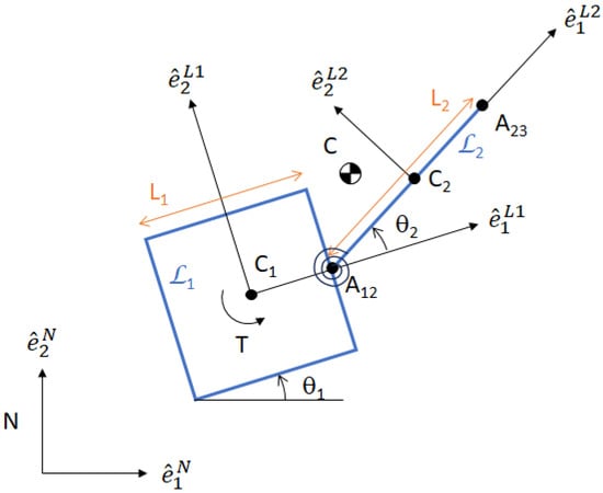
Figure 1.
Schematic of a planar free-floating two-rigid-body, torsional-spring-joint system, in flat space.
The generalized coordinates of the system include the absolute position of point C, relative to vector base in the inertial reference frame, and the internal configuration of the system , where is the absolute orientation of body with respect to , and is the relative orientation of with respect to . We define the generalized coordinate vector
The equation of motion of the system can be written as
where , , and represent the mass matrix, centrifugal terms matrix, and force matrix. These matrices are given in Appendix B.
As a free-floating system, linear momentum is conserved, so point C will conserve its initial velocity . Thus, the motion of the center of mass of the system is decoupled from the internal configuration of the system . Henceforth, we focus our analysis on the dynamics of the angular states .
Using small angle approximations, the equation of motion can be linearized:
where
Note that is the natural frequency of the system, is the coupling parameter, and is the input torque applied to body . For the system pictured in Figure 1, , , , and are given in Appendix B.
For a rest-to-rest problem, the initial state is , and the desired final state is . The objective is to find the control such that the final rest state can be obtained at final time .
This article considers an example system to illustrate the effects of various control strategies. The physical dimensions of the system are shown in Table 1. Such a parametrization gives Hz2, Hz2, rad kg−1 m−2, and rad kg−1 m−2.

Table 1.
Example system parameters.
Two problem cases are considered for this system:
- (a)
- Rest-to-Rest Example: Starting from rest, the system performs a 180° rotation.
- (b)
- Non-Rest-to-Rest Example: Starting with the initial nonzero values of all states, the system performs a 180° rotation and reaches a final rest state.
Note that in this article, for all examples, we assume that |u(t)| = 0.005 N.m.
3. Single Switch and ZVDD Input Shaping
References [15,17,18,19] showed that the minimum-time rest-to-rest control for a system with n flexible modes is a bang-bang control, which has optimal switches in “most cases”. For the two-body spring–mass system modeled in Section 2, the minimum-time rest-to-rest control has switches. However, this bang-bang control solution is not designed to reduce vibrations during the rest-to-rest rotational maneuver.
To address the vibration-reduction problem, we propose an alternative approach based on an approximate solution with a single switch. The advantage of a single-switch control is that the trajectory equations become very easy to solve, but the disadvantage is that it introduces vibrations at the final time. However, by using input shaping, such vibrations can be reduced and thus the “rest-to-rest” condition can be achieved.
The non-rest-to-rest rotational maneuver problem is complicated to solve, and the minimum number of switches to perform the rotation depends on two key factors, (a) the initial non-rest values and (b) the torque limit. Thus, the minimum number of switches required to perform the rotational maneuver can be greater than . Obviously, the single-switch based bang-bang and conventional ZVDD cannot guarantee the final resting condition. However, using the proposed method, a final rest condition or a “non-rest-to-rest” solution can be obtained.
3.1. Single-Switch Reference Signal
The proposed input shaping approach is based on the single-switch reference signal shown in Figure 2, with torque limit . Three points are labeled in the figure: point V2 is at the initial time , point V0 is at the final time , and point V1 is the switching point. The magnitude of the control is constant, with being between V2 and V1, and being between V1 and V0.
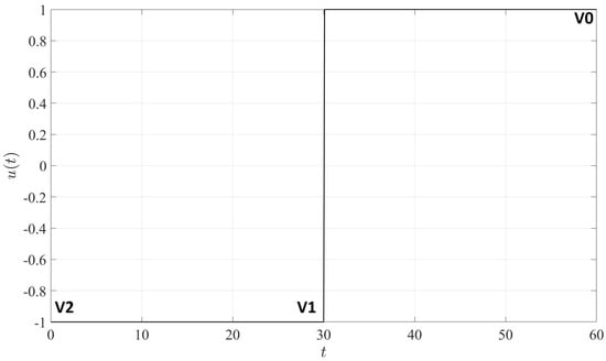
Figure 2.
A simple unit amplitude bang-bang control torque.
When this input is applied to the two-body system, the linearized equations of motion (3)–(5) can be solved for the system states at the switching points:
where . In Equations (6)–(9), the and terms have two subscripts; the first subscript indicates the body number (1 represents ; 2 represents ) and the second subscript indicates the point number ( indicates V2, etc.). The term represents the time interval between points v and . The control torque during the interval after switching point v is , where and .
By substituting Equation (9) for the last three terms of Equation (7), a simplified expression can be found that relates the velocities of the two bodies at consecutive switching points:
Equation (10) can be solved for , which gives a general expression for the duration of each switching interval:
For the rest-to-rest problem, if the initial state is , then . Likewise, if the final desired state is , then . From Equation (11) with the substitution , simplified expressions for the switching time intervals can be found:
If , then takes the following form:
Note that the denominator of Equation (14) is expressed in terms of , where = −.
Thus, for a single-switch control to solve the rest-to-rest problem, the time intervals must be identical: , where . Similarly, using Equations (6)–(9) and (13), simplified expressions can be found for the final states at point V0.
Equations (15)–(18) represent an over-determined system with no solution; there are no values of and that solve the equation set. Clearly, the single-switch torque profile shown in Figure 2 is not sufficient to perform a rest-to-rest rotation of a flexible body. When this torque profile is applied to the rest-to-rest example problem defined in Section 2, the resulting state trajectories are shown in Figure 3 by solving Equations (6)–(9). Note that the states do not all reach zero at the final time.
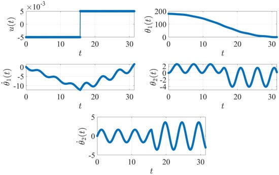
Figure 3.
Rest-to-rest case with single-switch, bang-bang torque. The plot units are degree ( and ), degree/second ( and ) and N.m ().
3.2. The Zero Vibration Derivative-Derivative (ZVDD) Input Shaper
For a second-order system with natural frequency and damping coefficient , the impulse response equation for a series of N impulses can be written as [20]:
where is the amplitude of each impulse, and indicates when it is applied.
The equation for the residual vibration generated from a series of impulses can be stated as follows:
where
The system under consideration in this article is a “spring–mass” system, so the damping ratio = 0.
The values for and can be obtained for various shapers [21,22,23]. Here, the ZVDD shaper is used because it offers more robustness than ZV and ZVD [10,24], and its trajectory equations are less complicated than ZVDDD. However, depending on the requirements, the proposed shaper can be easily converted to ZV and ZVD by tuning one or more parameters. Similarly, by setting the impulse amplitude values and other parameters, the proposed input shaper can be used as an EI shaper (by specifying the vibration tolerance level), two-hump EI shaper (specifying the impulse amplitude values as mentioned in Ref. [25]), and Specified Insensitive (SI) shapers [24,26,27]. Thus, robustness can be controlled (improved) by choosing the appropriate shaper based on the complexity of the system.
In the ZVDD shaper, the magnitudes of the impulses are constrained as defined in Equation (23):
The impulse time and amplitude matrix related to the ZVDD shaper can be written as
where and ( is the “damped natural frequency”). The values of , , and are 1/8, 3/8, 3/8, and 1/8 respectively, with = 0.
For a unit torque, single-switch reference control, the convoluted torque after using the conventional ZVDD shaper will have the form shown in Figure 4.
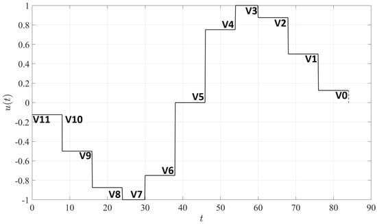
Figure 4.
An example of a convoluted torque after using the ZVDD input shaper.
For any ZVDD shaper, the convoluted torque can be summarized as shown in Table 2.

Table 2.
Convoluted torques for the ZVDD input shaper.
The convoluted torque with the ZVDD input shaper has a longer timespan than the reference single-switch torque profile. The time intervals in the reference torque profile shown in Figure 2 each correspond to four time intervals of the convoluted torque shown in Figure 4:
The remaining time intervals, , , and , extend beyond the duration of the single-switch control.
4. Rest-to-Rest Problem with Conventional ZVDD Input Shaping
Applying the conventional ZVDD shaped torque profile in Section 3.2 to the flexible two-body system model, it is possible to achieve a near-rest state and significantly reduce the final vibration. Let the time of the rotational maneuver be , where is the additional time due to the use of input shaping. From Equation (24), the time difference between each impulse will be = . So, we can write = = = = = = = = = = . Note that and will have different values.
Comparing Equations (25) and (26) to the convoluted torque profile, the convoluted profile is three time increments longer than the single-switch torque profile, so
The final value of at time can be analytically expressed as follows:
Equation (28) can be further simplified and written as follows:
Therefore, if is chosen such that
then .
The remaining states at time take the following form:
Note that to calculate Equations (28)–(33), a number of trigonometric formulas are used related to and . Please see Appendix A for more details.
In summary, Equations (29)–(33) show that the conventional ZVDD input shaping method can bring the two-body spring–mass to the desired rest state, but the method does not greatly reduce vibrations during the rotational/slew maneuver. When the ZVDD shaped torque profile is applied to the rest-to-rest problem defined in Section 2, the resulting state trajectories are shown in Figure 5.
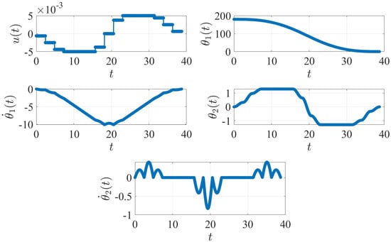
Figure 5.
Rest-to-rest case with conventional ZVDD input shaping. The plot units are degree ( and ), degree/second ( and ) and N.m ().
5. Non-Rest-to-Rest Trajectory with a Single-Switch Torque Input
The problem becomes more complicated for non-rest initial conditions, where , , and have non-zero values. As mentioned previously, we assume that the initial non-rest conditions are known. In these cases, the minimum number of switches for the non-rest-to-rest control problem is not limited to . As mentioned earlier, the minimum required number of switches changes with the initial conditions and the torque limit. We propose to solve the problem using a single switch reference trajectory with input shaping.
Suppose that = , = , and = , so the initial state takes the form and the final desired state is . Using Equation (11), the time increments and for the single-switch reference trajectory can be obtained:
Similar to Equation (14), if (or ≈0), then the following equation can be written:
Like the single-switch case with initial resting conditions, there will be vibrations at the final time for this case. The system states at time for the non-rest initial condition can be written as follows:
Clearly, if , , , and are all zero, then Equations (38)–(41) will be identical to Equations (15)–(18).
Consider the non-rest-to-rest problem defined in Section 2. When a single-switch torque input (|u(t)| = 0.005 N.m) is applied to the system with the non-zero initial condition, the resulting state trajectories are shown in Figure 6. Note that the system does not reach a final rest state.
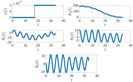
Figure 6.
Non-rest-to-rest case with single-switch, bang-bang torque. The plot units are degree ( and ), degree/second ( and ) and N.m ().
6. Non-Rest-to-Rest Problem with Conventional ZVDD Input Shaping
When the ZVDD shaped input is applied to a system with non-resting initial conditions, the system states at the final time are shown below:
Note that all four elements are non-zero even after using the ZVDD shaper. The impact of using the ZVDD shaper can be measured by subtracting Equations (42)–(45) from Equations (38)–(41). Clearly, if , , , and are zero, Equations (42)–(45) will be exactly the same as Equations (29)–(33).
When the ZVDD-shaped input is applied to the non-rest-to-rest example problem defined in Section 2, the resulting state trajectories are shown in Figure 7. In this case, unlike the rest-to-rest problem, none of the states come to rest at the final time.
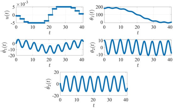
Figure 7.
Non-rest-to-rest case with conventional ZVDD input shaping. The plot units are degree ( and ), degree/second ( and ) and N.m ().
7. Numerical Optimization
Numerical optimization methods offer an alternative approach to solving the non-rest-to-rest flexible body rotation problem. However, these methods are often sensitive to the initial guess, the problem formulation, and the choice of algorithm parameters (e.g., mesh tolerance).
The optimal control software GPOPS-II [28] is used to solve the minimum-time rest-to-rest and non-rest-to-rest problems given in Section 2 using the linearized equations of motion. The results are shown in Figure 8 and Figure 9.
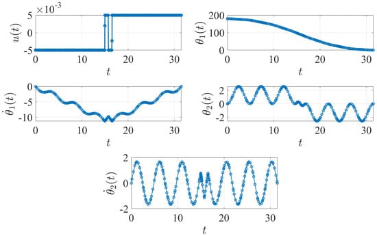
Figure 8.
Rest-to-rest case with minimum-time control found using GPOPS-II. The plot units are degree ( and ), degree/second ( and ) and N.m ().
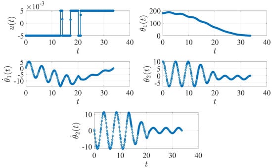
Figure 9.
Non-rest-to-rest case with minimum-time control found using GPOPS-II. The plot units are degree ( and ), degree/second ( and ) and N.m ().
In both cases, GPOPS-II is able to find the minimum-time optimal control solution and achieve resting conditions. The solution of the rest-to-rest problem has three switches, while the solution of the non-rest-to-rest problem has five () switches.
8. The Optimized ZVDD Input Shaper
As shown in Section 6, the conventional, single-switch-based ZVDD input shaper is unable to produce the final rest condition from a non-resting initial condition.
This article proposes a numerical solution that is based on the idea of an optimized ZVDD shaper using the Multi-Start algorithm [29,30]. The Multi-Start method is a global optimization technique and available in the MATLAB (R2023b) global optimization toolbox. The concept of the Multi-Start algorithm is based on the use of multiple starting points; it first creates several uniformly distributed starting points, then runs local solvers (this article uses sequential quadratic programming [31,32]) on these starting points, improves the solution, and finally generates the solution for which the objective function has the lowest value.
Before discussing the optimization technique and describing examples, some key elements related to the optimization procedure are outlined. For the conventional ZVDD shaper shown in Figure 4, for a system with , the time increment is and the final time will be . However, for an optimized solution, the impulses will not be prescribed at uniform time increments. The proposed solution uses three time intervals, , defined as follows:
where the final time will be . For the final rest condition, the values of , , , and at the final time must be equal to 0. Further,
Additionally,
For the ZVDD shaper, there are seven unknowns: , , , , , , and . The magnitude of the fourth impulse is constrained by Equation (23). The proposed optimization strategy is shown in Problem (46):
In Problem (46), the values of , ( limits), , ( limits) and , ( limits) can be set depending on the required configuration. Symbolic expressions for the final values of the states, , , , and , are given in Appendix C. The value of can be predefined to any value (greater than or equal to the minimum-time optimal control time value). Additionally, , , , and , , , and are upper and lower bounds for different time intervals.
The term refers to the parameters or factors which are multiplied by the actual values of the torque (see Table 2). For example, from V11 to V10, the factor is . Likewise, from V6 to V5, the factor becomes ; by limiting the values of these factors within , we ensure that the shaped torque never exceeds the maximum or minimum allowable torque limits.
It is possible to obtain a near-zero value for (at the end) using the conventional ZVDD shaper for the rest-to-rest problem, but the optimized ZVDD shaper offers three other additional benefits besides ensuring a final rest condition. These advantages are the following: (a) the optimized ZVDD shaper can be used to significantly reduce vibration for rest-to-rest problems, (b) complete the maneuver in a predefined fixed time, and (c) customize one or more optimization parameters (e.g., to define the impulse amplitudes or the duration between impulses).
For the two example problems defined in Section 2, the Multi-Start algorithm is used to solve the optimal control problem defined in Problem (46) with uniformly distributed starting points and a numerical tolerance value of .
8.1. Example-1, Rest-to-Rest Example
For the rest-to-rest example problem, the result obtained using the proposed method is presented in Figure 10.
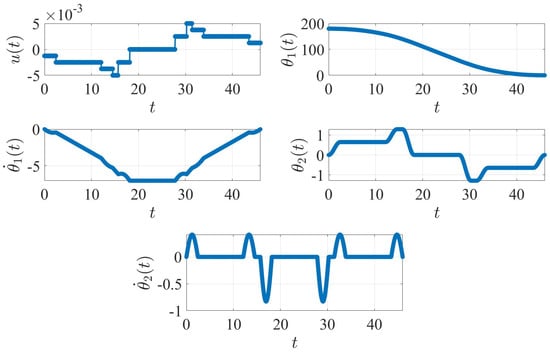
Figure 10.
Rest-to-rest case with optimized convoluted torque. The plot units are degree ( and ), degree/second ( and ) and N.m ().
To perform the optimization, two sets bounds are defined as follows:
- (a)
- Impulse amplitude constraints: = = = 0.25.
- (b)
- Time increments constraints: .
Comparing the minimum-time control solution obtained using GPOPS-II in Figure 8 with the numerically optimized solution of the ZVDD shaped problem in Figure 10, it is clear that both reach a resting final state, but the proposed method significantly reduces the magnitude of the vibration of , , and during the maneuver. To visually compare the minimum time solution of GPOPS-II and the optimized shaper, an overlapped plot is generated for the four angular components and displayed using Figure 11.
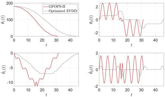
Figure 11.
Comparison of GPOPS-II minimum time control (red) and optimized ZVDD performance (black) for rest-to-rest control. The plot units are degree ( and ) and degree/second ( and ).
Table 3 shows a comparison between the results of four types of torque profiles: the single-switch bang-bang torque, conventional ZVDD, baseline numerically optimized using GPOPS-II, and the proposed optimized ZVDD method.

Table 3.
Summary of various test results obtained using different torque inputs for the rest-to-rest problem.
Remark 1.
For rest-to-rest and non-rest-to-rest problems (minimum time optimal control problem), the GPOPS-II optimal control software produces exact zero final states (as shown in Table 3). However, if the torque profile produced by GPOPS-II is used with the linear/nonlinear dynamics model with an ODE solver (e.g., ODE89, https://www.mathworks.com/help/matlab/ref/ode89.html, (accessed on 8 January 2025)), then the result is an approximately zero final state (not an exact zero). For example, as shown in Table 3, all final values are zero using GPOPS-II but using ODE89 (using the same torque profile produced by GPOPS-II), the final state is [0.3331°, 0.0483°/s, 0.0048°, −0.0985°/s]T.
8.2. Example-2, Non-Rest-to-Rest Example
For the non-rest-to-rest example problem, the result obtained using the proposed method is presented in Figure 12.
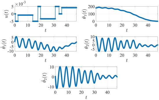
Figure 12.
Non-rest-to-rest case with optimized convoluted torque. The plot units are degree ( and ), degree/second ( and ) and N.m ().
In this example, two bounds are defined as follows:
- (a)
- Impulse amplitude constraints: .
- (b)
- Time increment constraints: .
In Figure 12, all four elements of the state vector reach zero at the end of the rotational maneuver. Table 4 summarizes the results obtained after using different methods.

Table 4.
Summary of various test results obtained using different methods for non-rest-to-rest condition.
Since, for the non-rest-to-rest example, vibration reduction is not a priority but rather the goal is to reach the final “rest”state regardless of the initial conditions (and the minimum number of switches required), we do not compare the optimized ZVDD solution with the minimum-time GPOPS-II solution.
9. Conclusions
This paper discusses the rest-to-rest and non-rest-to-rest control of an undamped, planar, two-body spring–mass model using the four-impulse optimized ZVDD input shaping method. The proposed method is useful to guarantee the final rest condition. For the rest-to-rest control problem, the traditional ZVDD input shaper can bring the final state to rest, but it does not mitigate vibrations during the motion. The proposed optimized input shaper not only brings the final state to rest but also reduces the vibrations for the rest-to-rest problem.
The non-rest-to-rest problem is an extremely complicated problem to solve, as the minimum number of switches depends on a number of different factors, including the initial state values. This article shows that the traditional ZVDD shaper results in significant non-zero values for the final state. However, the proposed shaper is able to solve the non-rest-to-rest control problem regardless of the initial non-rest values, so the proposed method is useful regardless of the minimum number of switches.
Author Contributions
Conceptualization, S.B. and J.H.; methodology, S.B.; software, S.B.; validation, S.B., J.J.K. and J.H.; formal analysis, S.B.; investigation, S.B. and J.J.K.; resources, S.B.; data curation, S.B.; writing—original draft preparation, S.B.; writing—review and editing, S.B., J.J.K. and J.H.; visualization, S.B.; supervision, J.H. and J.J.K.; funding acquisition, J.H. All authors have read and agreed to the published version of the manuscript.
Funding
The project or effort undertaken was or is sponsored by the Department of the Navy, Office of Naval Research, Consortium for Robotics Unmanned Systems Education and Research at the Naval Postgraduate School.
Institutional Review Board Statement
Not applicable.
Informed Consent Statement
Not applicable.
Data Availability Statement
The original contributions presented in this study are included in the article. Further inquiries can be directed to the corresponding author(s).
Conflicts of Interest
The authors declare no conflicts of interest. The funders had no role in the design of the study; in the collection, analyses, or interpretation of data; in the writing of the manuscript; or in the decision to publish the results.
Appendix A. Trigonometric Identities
When
Appendix B. Dynamic System Constants
The centrifugal terms matrix C has the form
where
The force matrix includes the input torque applied at the spacecraft bus, link , and the force of the torsional spring at point
Note that , , , , , and designate the mass of the spacecraft bus, mass of the solar panel, side length of the bus, length of the solar panel, and moments of inertia of the two bodies, respectively. M denotes the total mass of the system, . Moreover, if the thickness of the solar panel is represented by the term , then and take the following form:
Equations (A9) and (A10) do not depend on ; it is the angle of with respect to the inertial frame, so it does not affect the vibrational motion. Also note that the linearized equations do not depend on either. If the system rotates at a constant speed with no vibration of the beam (i.e., = 0 and = 0), then the value of would not matter; fast spin speed or slow spin speed would not cause vibration. So for the first order, does not directly affect the accelerations of the system.
Note that , , and can be written as follows:
Appendix C. Trajectory Equations for Optimization
In Equations (A15)–(A18), , , , and indicate angular values at V0 (see Figure 4 and Table 2). Likewise, , , , and are the angular values at V1. Of course, these values are related to , , , and , i.e., the angular values at V11 or at the beginning (at ), which are known. The torque and time interval (or “Segment Time”) values can be used by following Table 2.
References
- Karpenko, M.; Stosiak, M.; Deptuła, A.; Urbanowicz, K.; Nugaras, J.; Królczyk, G.; Żak, K. Performance evaluation of extruded polystyrene foam for aerospace engineering applications using frequency analyses. Int. J. Adv. Manuf. Technol. 2023, 126, 5515–5526. [Google Scholar] [CrossRef]
- Huh, C.D.; Hong, K.S. Input shaping control of container crane systems: Limiting the transient sway angle. IFAC Proc. Vol. 2002, 35, 445–450. [Google Scholar] [CrossRef]
- Mohammed, A.; Alghanim, K.; Taheri Andani, M. An adjustable zero vibration input shaping control scheme for overhead crane systems. Shock Vib. 2020, 2020, 1–7. [Google Scholar] [CrossRef]
- Singhose, W.; Porter, L.; Kenison, M.; Kriikku, E. Effects of hoisting on the input shaping control of gantry cranes. Control Eng. Pract. 2000, 8, 1159–1165. [Google Scholar] [CrossRef]
- Kasprowiak, M.; Parus, A.; Hoffmann, M. Vibration suppression with use of input shaping control in machining. Sensors 2022, 22, 2186. [Google Scholar] [CrossRef] [PubMed]
- Doherty, M.J.; Tolson, R.H. Input Shaping to Reduce Solar Array Structural Vibrations; [NASA Contractor Report]; NASA/CR-1998-208698; National Aeronautics and Space Administration, Langley Research Center: Hampton, VA, USA, 1998. [Google Scholar]
- Hu, Q. Input shaping and variable structure control for simultaneous precision positioning and vibration reduction of flexible spacecraft with saturation compensation. J. Sound Vib. 2008, 318, 18–35. [Google Scholar] [CrossRef]
- Park, K.; Lee, J.; Park, J. Torque control of a vehicle with electronic throttle control using an input shaping method. Int. J. Automot. Technol. 2013, 14, 189–194. [Google Scholar] [CrossRef]
- Mann, G.J.; Danilochkin, P.; Singhose, W.E. Attenuation of Initial Oscillation in Bridge Cranes via Input-Shaping-Based Feedback Control Methods. In Proceedings of the Dynamic Systems and Control Conference, Fort Lauderdale, FL, USA, 17–19 October 2012; pp. 813–822. [Google Scholar] [CrossRef]
- Conker, C.; Yavuz, H.; Kapucu, S.; Baltacioglu, M.; Arat, H.; Burgaç, A. Comparison of robust input shapers for elimination of residual vibrations. Appl. Mech. Mater. 2014, 490–491, 997. [Google Scholar] [CrossRef]
- Romano, M.; Agrawal, B.N.; Bernelli-Zazzera, F. Experiments on command shaping control of a manipulator with flexible links. J. Guid. Control. Dyn. 2002, 25, 232–239. [Google Scholar] [CrossRef]
- La-orpacharapan, C.; Pao, L. Fast and robust control of systems with multiple flexible modes. IEEE/ASME Trans. Mechatronics 2005, 10, 521–534. [Google Scholar] [CrossRef]
- Newman, D.; Hong, S.W.; Vaughan, J.E. The design of input shapers which eliminate nonzero initial conditions. J. Dyn. Syst. Meas. Control 2018, 140, 101005. [Google Scholar] [CrossRef]
- Dhanda, A.; Vaughan, J.; Singhose, W. Optimal input shaping filters for non-zero initial states. In Proceedings of the 2009 American Control Conference, St. Louis, MO, USA, 10–12 June 2009; pp. 4141–4146. [Google Scholar] [CrossRef]
- Barbieri, E.; Ozguner, U. A new minimum-time control law for a one-mode model of a flexible slewing structure. IEEE Trans. Autom. Control 1993, 38, 142–146. [Google Scholar] [CrossRef]
- Ebrahimi, A.; Moosavian, S.; Mirshams, M. Minimum-time optimal control of flexible spacecraft for rotational maneuvering. In Proceedings of the 2004 IEEE International Conference on Control Applications, Taipei, Taiwan, 2–4 September 2004; Volume 2, pp. 961–966. [Google Scholar] [CrossRef]
- Ben-Asher, J.; Burns, J.A.; Cliff, E.M. Time optimal slewing of flexible spacecraft. In Proceedings of the 26th IEEE Conference on Decision and Control, Los Angeles, CA, USA, 9–11 December 1987; Volume 26, pp. 524–528. [Google Scholar] [CrossRef]
- Pao, L.; Franklin, G. Time-optimal control of flexible structures. In Proceedings of the 29th IEEE Conference on Decision and Control, Honolulu, HI, USA, 5–7 December 1990; Volume 5, pp. 2580–2581. [Google Scholar] [CrossRef]
- Singh, G.; Kabamba, P.T.; Mcclamroch, N.H. Planar, time-optimal, rest-to-rest slewing maneuvers of flexible spacecraft. J. Guid. Control. Dyn. 1989, 12, 71–81. [Google Scholar] [CrossRef]
- Ha, M.T.; Kang, C.G. Experimental analysis of natural frequency error to residual vibration in ZV, ZVD, and ZVDD shapers. In Proceedings of the 2013 10th International Conference on Ubiquitous Robots and Ambient Intelligence (URAI), Jeju, Republic of Korea, 30 October–2 November 2013; pp. 195–199. [Google Scholar] [CrossRef]
- Singhose, W.; Mills, B.; Seering, W. Vibration reduction with specified-swing input shapers. In Proceedings of the 1999 IEEE International Conference on Control Applications (Cat. No.99CH36328), Kohala Coast, HI, USA, 22–27 August 1999; Volume 1, pp. 533–538. [Google Scholar] [CrossRef]
- Singh, T.; Singhose, W. Input shaping/time delay control of maneuvering flexible structures. In Proceedings of the 2002 American Control Conference (IEEE Cat. No.CH37301), Anchorage, AK, USA, 8–10 May 2002; Volume 3, pp. 1717–1731. [Google Scholar] [CrossRef]
- Vaughan, J.; Yano, A.; Singhose, W. Comparison of robust input shapers. J. Sound Vib. 2008, 315, 797–815. [Google Scholar] [CrossRef]
- Singhose, W.; Seering, W.; Singer, M. Input Shaping for Vibration Reduction With Specified Insensitivity to Modeling Errors. In Proceedings of the Japan-USA Symposium on Flexible Automation, Boston, MA, USA, 7–10 July 1996; Volume 1. [Google Scholar]
- Singhose, W.E.; Porter, L.J.; Tuttle, T.D.; Singer, N.C. Vibration Reduction Using Multi-Hump Input Shapers. J. Dyn. Syst. Meas. Control 1997, 119, 320–326. [Google Scholar] [CrossRef]
- Vaughan, J.; Yano, A.; Singhose, W. Performance comparison of robust negative input shapers. In Proceedings of the 2008 American Control Conference, Seattle, WA, USA, 11–13 June 2008; pp. 3257–3262. [Google Scholar] [CrossRef]
- Pai, M.C. Robust input shaping control for multi-mode flexible structures using neuro-sliding mode output feedback control. J. Frankl. Inst. 2012, 349, 1283–1303. [Google Scholar] [CrossRef]
- Patterson, M.; Rao, A. GPOPS-II: A MATLAB software for solving multiple-phase optimal control problems using hp-adaptive gaussian quadrature collocation methods and sparse nonlinear programming. ACM Trans. Math. Softw. 2014, 41, 1–37. [Google Scholar] [CrossRef]
- Pajor, T.; Uchoa, E.; Werneck, R. A robust and scalable algorithm for the Steiner problem in graphs. Math. Program. Comput. 2014, 10, 69–118. [Google Scholar] [CrossRef]
- Martí, R.; Moreno-Vega, J.M.; Duarte, A. Advanced Multi-start Methods. In Handbook of Metaheuristics; Springer: Boston, MA, USA, 2010; pp. 265–281. [Google Scholar] [CrossRef]
- Ansary, A.; Panda, G. A sequential quadratic programming method for constrained Multi-objective optimization problems. J. Appl. Math. Comput. 2020, 64, 379–397. [Google Scholar] [CrossRef]
- Boggs, P.; Tolle, J. Sequential quadratic programming for large-scale nonlinear optimization. J. Comput. Appl. Math. 2000, 124, 123–137. [Google Scholar] [CrossRef]
Disclaimer/Publisher’s Note: The statements, opinions and data contained in all publications are solely those of the individual author(s) and contributor(s) and not of MDPI and/or the editor(s). MDPI and/or the editor(s) disclaim responsibility for any injury to people or property resulting from any ideas, methods, instructions or products referred to in the content. |
© 2025 by the authors. Licensee MDPI, Basel, Switzerland. This article is an open access article distributed under the terms and conditions of the Creative Commons Attribution (CC BY) license (https://creativecommons.org/licenses/by/4.0/).