Abstract
This research addresses the challenge of digitizing the surface of objects in hard-to-reach areas and focuses on the integration of reverse engineering techniques with innovative digitization approaches. Conventional non-destructive testing techniques, such as industrial videoscope inspection, lack the ability to capture accurate geometric and surface information without the need for disassembly of the components. To overcome these limitations, this research proposes a 3D digitizing prototype that integrates structured light, laser scanning, and active stereo techniques. The device utilizes ESP32-CAM modules and compact mechanical components designed for portability and usability in confined spaces. Experimental validation involved scanning complex and reflective surfaces, including printer components and the engine compartment of an automobile, demonstrating the device’s ability to produce detailed point clouds in challenging environments. Key innovations include a unique approach for utilizing 3D scanning techniques of active stereovision using a folding mechanism. The findings highlight the device’s potential for applications in technical diagnostics, industrial inspection, and environments where traditional digitizing technologies could not be utilized.
Keywords:
stereovision; 3D scanning; reverse engineering; digitization; scanner; point cloud; prototype 1. Introduction
The implementation of reverse engineering technologies in the field of hard-to-reach diagnostics is currently one of the research challenges in several industry sectors, including manufacturing, transportation, energy, medical, and other sectors [1]. Visual inspection as a method of engineering diagnosis has been used for several decades in the diagnosis of hard-to-reach areas [2]. In certain areas of its application, this diagnostic method is the fastest and least expensive, and in certain cases, it is the only usable method within non-destructive testing. For this purpose, endoscopic devices, especially industrial videoscopes, are used. Their utilization in the field of diagnostics of hard-to-reach places provides several advantages, e.g., rapidity of obtaining the necessary information, relatively low costs of the technology compared to other technologies of non-destructive testing, etc. The main disadvantages of conventional endoscopic inspection can be considered to be the acquisition of only images of the surface without spatial information about its shape and surface [3]. For this reason, it is not possible to effectively and accurately measure the geometry of the surface geometry features of objects and their extent, which include cracks, defects, and other damage. To obtain this information, particularly the distance between the sensor and the surface points of objects, research is being conducted on the implementation of reverse engineering elements in the field of diagnostics of hard-to-reach places. A challenge in this area is the use of reverse engineering techniques within confined spaces. The reverse engineering techniques currently used require a certain minimum amount of space for the implementation of the digitization process in order to use the digitization equipment. Minimum mutual distance between the sensors and the object are also required. Furthermore, conventional digitizing devices are, in most cases, designed in sizes that do not allow their utilization within hard-to-reach places. Due to technological advances, sensor, reverse engineering, and endoscopy technologies are continuously being developed with the aim to develop technologies with higher resolution, higher accuracy, and smaller dimensions. This fact allows their progressive implementation in the field of hard-to-reach diagnostics, and this paper is dedicated to this issue.
To address this challenge, an in-depth analysis of the current state of the art and knowledge in the field of reverse engineering and its available techniques and technologies is needed. Subsequently, it is necessary to describe the implementation of non-destructive testing and the possibilities of using reverse engineering in areas of hard-to-reach places. With this knowledge in mind, it is necessary to design a prototype digitizing device usable in these areas. A suitable reverse engineering technique needs to be selected for use within this facility. With respect to the available reverse engineering techniques, it is necessary to analyze them step by step and arrive at a suitable way of implementing this technique. For this proposal, it is necessary to think with an “outside of the box” strategy based on the use of innovative ideas and atypical solutions, as there are currently no commercially available digitizing devices for use in the field of diagnostics of hard-to-reach places. The correct selection of available reverse engineering techniques and their use in an innovative way is crucial.
In the field of digitizing hard-to-reach places, Ref. [4] proposed a 3D digitizing device based on surface scanning using multiple images at different angles and using structured light techniques without the need for calibration. In digitizing using this device, unlike conventionally structured light-based digitizing devices, there is no need to calibrate the device, after which it would be necessary to maintain the device in the same location in space. As a result, details of the shaped surface can be better captured at multiple angles, while the accuracy of the acquired data is higher. In the digitizing process, it is possible to change the position of the projector or camera within the space but not of both in the same process. Subsequently, the researchers of [5] developed a self-calibrating active digitizing device using a laser scanning technique employing line lasers and a single camera. A device with a projector of two laser lines and a camera was built, and the device can be freely moved within the space during the digitization process, and thus, the surface of the object can be digitized. The device uses a sequence of frames for calibration and depth measurement, during which the laser projector is moved backwards and forwards. The device records a constant point as the intersection of two laser lines at an angle of 90°. Utilizing this technique, the authors of [6] measured the three-dimensional distance to the gastric surface in medicine by image processing of the stereo matching method. As part of the subsequent research, the authors of [7] followed up on previous work in digitizing the object using laser techniques and self-calibration. In this work, they presented a 3D dense point cloud acquisition technique based on a laser digitization technique using projection of line lasers onto planar surfaces. As the basic information for 3D data acquisition, the projected laser curves on planar surfaces are captured by a single camera at a viewing angle non-parallel to the laser beam source, where the laser beam source and the projected beam are repositioned, and the camera position is constant in the process. In particular, the description of the process and the numerical calculation required for obtaining a 3D surface model of planar objects by the laser technique can be considered as a contribution of this work. The authors of [8] presented a 3D endoscopic digitizing device using the “active stereo” technique. The active stereo technique can be defined as a digitizing technique using one or more structured light projectors and one or more cameras, whereby the light pattern of a mesh grid is projected onto an object, and the surface of the object is calculated based on the distribution of the light pattern on the object. The projector was composed of a laser light projector and an optical fiber transmitting the light source to a projector head located on the outside of the endoscope using a thin and flexible tube. The endoscopic device recorded an image with blurring, which had to be compensated for by an algorithm in the endoscope calibration process. In contrast to the structured light technique using the encoding of positional information within shape patterns explicitly, in the active stereovision technique, the intersection lines of the laser beams were implicitly used as reference points for the computation of the surface in space. A complex process was used to calibrate the projector by projecting the image pattern through the display, which was recorded by a separate camera, not an endoscopic camera; then, the laser pattern was projected onto the display. The projected pattern could then be aligned with the shape image on the display. In a practical validation of the device, a distance measurement error of 0.89% and an angle measurement error of 2.17% were recorded. The authors of [9] presented a method of calibration of a device for measuring the shape and size of objects for the examination of body parts in the field of medical diagnostics, a prototype 3D endoscopic device with an active stereovision technique. The proposed calibration method did not require the use of a calibration camera other than the endoscopic camera, using a device with a spherical surface shape for calibration, and at the same time, there was no need to distinguish between the distance of the calibration camera and the endoscopic camera. The authors of [10] followed up on previous work and improved the design of the prototype device. Instead of placing the laser beam projector on the outside of the endoscope, the authors implemented it in the head of the endoscope, reducing the diameter of the prototype device head. A diffractive optical element (DOE) was chosen at the end of the projector. Simultaneously, this implementation made it possible to introduce self-calibration of the device. Since the projector achieves 2 degrees of freedom when the device is working and when the device head is moving—namely, displacement in the axial direction and rotation about the axis—they proposed to create a mark on the projector for calibration, which is detected by the endoscopic camera. In this way, the orientation and relative position of the camera and projector can be determined and included in the calculations for calibration. Previous work in the development of a prototype 3D endoscopic device has been followed up on by the authors of [11]. Focused on calibrating a device whose projector was not statically mounted in the endoscope head, the authors determined that the device could not be pre-calibrated. To eliminate the need for complex and inaccurate calibration of the device using markers on the projector, a neural network was designed that senses and uses 10 point markers from the projected pattern. The device only needs to be calibrated once, and despite projector movement, the device will be correctly calibrated during the digitizing process. The advantage is the ability to digitize surfaces on a larger scale, as the object can be digitized in parts, and the acquired data can be merged. The device has been practically verified by digitizing the inside of a pig stomach, whereby the object was digitized in parts using more than 200 images, and the surface data acquired were combined into a complex model. The authors of [12] used the measurement of object surfaces employing the GelSight Max device, which uses reflectance transformation imaging against a gel-backed elastomer tactile membrane, for the topographic measurement of stone tool surfaces. This device may be used for surface digitization in hard-to-reach areas, but at present, it can only be used to digitize surfaces of small size and presents limitations in terms of the surface complexity. It is worth investigating the use of this technology for digitization of hard-to-reach areas in future research.
2. Materials and Methods
The formulation of the research objectives is based on the analysis of the problem addressed in the field and the summary of the existing knowledge. Previous research in the area of implementation of reverse engineering elements in the field of diagnostics of hard-to-reach areas has been primarily focused on the use of 3D endoscopic devices for measuring the shape areas of physical objects [13]. In particular, digitizing techniques using stereovision with multiple variations and configurations of devices, techniques using structured light, techniques using laser triangulation, and other specific digitizing techniques have been used in the research [14].
The main objective of the research is to design a prototype digitizing device for performing digitization of objects in hard-to-reach places. The partial objectives include the analysis of the current state of digitization of objects in hard-to-reach places, description of theoretical background in reverse engineering, digitization of physical objects and technical diagnostics in the field of hard-to-reach places, design and selection of suitable digitization technique and hardware components for the prototype digitization device, the design of a software for performing digitization with the prototype device, the design of models of the assembly and mechanisms of the prototype digitization device, the production of their physical models and verification of the functionality of the prototype digitization device by performing digitization of objects in hard-to-reach locations, and the design of future research.
2.1. Technical Diagnostics in Hard-to-Reach Places
Hard-to-reach places within the industrial environment are not clearly defined. Hard-to-reach places can be considered as areas where it is not possible to perform the required activities and to use conventional technologies used in a typical environment, and the definition of “hard to reach” can be approached from several perspectives. In each industry sector, hard-to-reach places may be different and industry-specific. In terms of the environment in which the technology is used, hard-to-reach places can be divided into the following:
- Inaccessible environments;
- Underwater environments;
- Inaccessible environments in architecture and inspection of buildings and structures;
- Underground environments;
- Hard-to-reach environments with dimensionally restricted access openings;
- Environments with limited working space and tight environments;
- Confined working environments;
- Areas with small objects and angled surfaces;
- Environments with access that is legally restricted;
- Hazardous environments.
Hard-to-reach places can also include environments with harmful influences, hazardous environments, and environments in excessively low and high temperatures. In industrial and manufacturing environments, in particular, environments with dimensionally restricted access openings, environments with limited working space, and enclosed working environments can be considered as hard-to-reach places. Technical diagnostics is an engineering discipline dealing with methods and means of detecting technical conditions. The aim of technical diagnostics is to detect hidden faults, fault areas, and their extent and causes. It seeks to increase reliability, reduce operating costs, and ensure safe operation. Diagnostics is a set of processes carried out in a well-defined sequence in order to evaluate the technical condition of the object under examination. For objects examined by technical diagnostics, it must be possible to identify the functional and fault conditions. In the context of technical documentation, three activities can be applied to the object of technical condition investigation: to diagnose the current state of the technical condition (diagnosis), to predict the future state of the technical condition (prognosis), and to determine the history of the condition (genesis) [15]. Technical diagnostics in the current state of the art can be divided into the following:
- Vibrodiagnostics—diagnostics based on vibration testing;
- Thermodiagnostics—diagnostics based on temperature testing;
- Acoustic or noise diagnostics;
- Boroscopic, endoscopic, and videoscopic diagnostics—inspection of the interior of machinery and equipment;
- Pressure diagnostics;
- Diagnostics of shape deformations;
- Water level diagnostics;
- Fluid flow diagnostics;
- Heat and energy diagnostics;
- Concentration diagnostics;
- Gas emission diagnostics;
- Defectoscopy diagnostics—defectoscopy;
- Tribodiagnostics—investigation of oil lubricity and wear of machine parts;
- Diagnostics based on modal analysis of dynamic behaviour;
- Electrical diagnostics—electrodiagnostics;
- Multiparametric diagnostics using several diagnostic methods [15].
Due to the fact that the field of digitizing physical objects within reverse engineering is based on the acquisition of coordinate points of the surface areas of these objects, only diagnostic techniques related to the investigation of the shape areas of the surface of physical objects can be considered relevant when applying reverse engineering techniques to hard-to-reach places. For this reason, boroscopic, endoscopic, and videoscopic diagnostics, shape deformation diagnostics, defectoscopic diagnostics, and multiparametric diagnostics can be considered among the relevant diagnostic techniques in the field of hard-to-reach places. These diagnostic techniques belong to the field of non-destructive testing (NDT) [16]. In addition to NDT, 3D scanning and measurement, microscopy for the diagnosis of small objects, emulation of virtual environments or systems in virtual space, and physical disassembly and disassembly of system parts can be used in the field of hard-to-reach diagnostics. In the field of technical diagnostics in hard-to-reach locations, in general, it is possible to distinguish the following inspections:
- Geometric shapes, deviations, and tolerances;
- The position of objects;
- Component assemblies and assembly status;
- Defects and deformations—porosity, delamination of composites, cracks, fracture damage of components, corrosion, deformations after collisions, deformations due to forces, stresses and fatigue, and inspection after exposure to electricity and lightning;
- The presence of undesirable elements—the presence of objects and liquids, flow restricting elements, and crystallized substances;
- Imperfections and undesirable elements as a consequence of the manufacturing process—mold residues in castings, residues of core burn in castings, and the presence of chips after machining;
- The volume of material and fluids in containers and tanks—an excess or shortage of material or fluids;
- Joints and joining elements—peeling parts and missing adhesion elements and inspection of welds [17].
2.2. CAD Design of the Prototype
When designing the prototype device, the aim was to achieve the smallest possible dimensions of the device so that it could be placed within the space of hard-to-reach places within a confined environment. At the same time, it was important to design the components to be small in size and light in weight while maintaining their strength within the fused filament fabrication (abbr. FFF) manufacturing process. Clearances between components had to be chosen when producing the physical models. For moving parts, clearances had to be chosen so that the parts could be moved but, at the same time, not be too loose. For this reason, it was necessary to focus on the accuracy and quality of the manufactured parts. At the beginning, it was necessary to choose the basic principle of the mechanism within which the projected laser pattern on the digitized object would change its position. Rotation of the laser pattern projector is not suitable for use within the proposed program and prototype digitizing equipment. Therefore, it was necessary to propose a mechanism in which the laser pattern will be shifted to the left or right based on the need within the digitizing process. The basic idea of the proposed mechanism, as can be seen in Figure 1, is the use of folding arms with ESP32-CAM devices, manufactured and sourced by AI Thinker, Shenzen, China, the use of a laser projector, rotating guide rod rotating in single-row ball bearings, and the use of a linear bearing for the movement of the arms, with the attached arm holder moving in a precise cam.
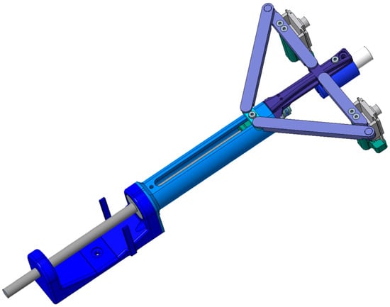
Figure 1.
Assembly view of the design of the prototype digitizing device.
First, a component was designed as the basic part holding the whole assembly and to which other components of the assembly are subsequently assembled. This base part can be attached to the tripod or mechanical arm with an M3 screw, as can be seen in Figure 2. This part holds the whole mechanism and needs to be moved when moving the device to hard-to-reach places. It was necessary to design this component to be of sufficient strength. As part of the basic part, fitting shapes were designed to hold two 608 2RS single-row ball bearings. These bearings were chosen because of their Ø8 mm inner diameter (into which the Ø8 mm diameter guide rod is placed). The guide rod is secured against axial displacement and can be manually rotated by the user. A part to which the laser projector holder is attached by an elastic cord is attached to the front end of the guide rod. As the guide rod rotates, the laser mount rotates around an axis in a radial (perpendicular) direction to the axis of the projector. The ESP32-CAM-MB manufactured and sourced by AI Thinker, Shenzen, China, power supply part of the ESP32-CAM can be attached to the base part.
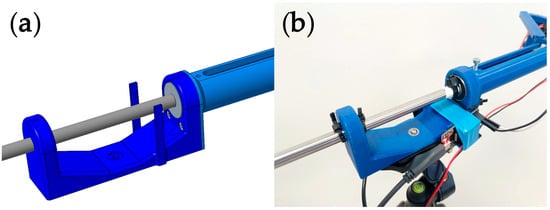
Figure 2.
Base component. (a) CAD view of the base part assembly. (b) Photo of the base part of prototype digitizing device.
A component with a guide groove is attached to the base part with two screws to guide the movement and prevent rotation of the linear bearing. This can be seen in Figure 3. A lightweight, plastic linear-bearing RJ4JP-01-08 LM8UU was placed on the guide rod, and the use of a plastic bearing without a ball system allows not only the displacement of the bearing but also the rotation of the guide rod to be performed almost without resistance. A hole for an M3 bolt was drilled on the linear bearing in the middle of its length in the normal direction to the axis. This bolt is used to attach the arm bracket. PTFE Teflon tape is wound on the arm holder. This reduces friction between the holder and the guide groove and compensates for the unevenness caused by the production of physical models by FFF technology.
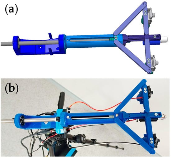
Figure 3.
Assembly of the design of the prototype digitizing device. (a) CAD view of the assembly. (b) Photo of the assembly of prototype digitizing device.
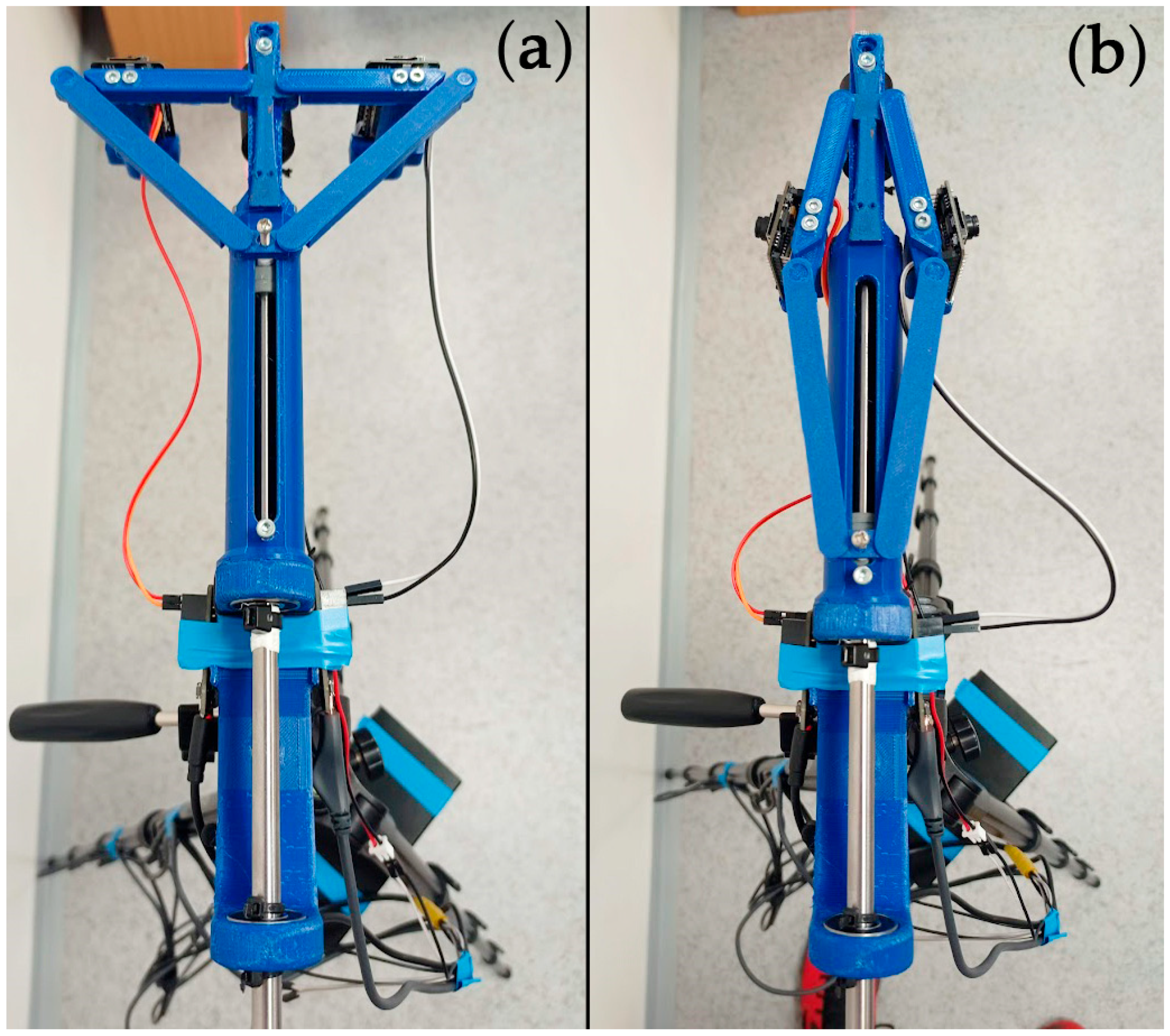
The user, while manually sliding the arm holder, performs a sliding motion of the linear bearing, and at the same time, the motion is guided in the guide groove from one end position to the other end position. In the first position, the arm holder is moved to the front end position in the direction toward the laser projector, as can be seen in Figure 4a. Within this position, calibration is performed. Within the software, the OpenCV 4.7.0 libraries [18] were used to calibrate the device. Once the calibration has been performed, the user moves the arm holder to the other end position away from the laser projector, as can be seen in Figure 4b, with the camera arms folded down. Within this change in position, a change in the external parameters of the device is performed. In this position, the device can be moved into areas of difficult access. Once in the hard-to-reach area, the arm holder can be moved to the forward position to return the device to its position during calibration. This will return the values of the external parameters of the device to the values during calibration.
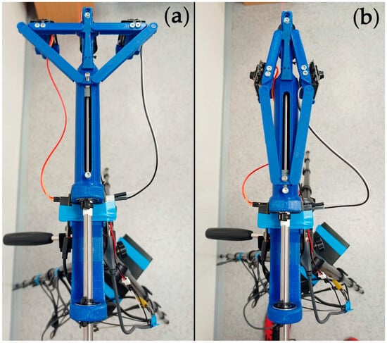
Figure 4.
Representation of the mechanism movement of the prototype device. (a) First device position during calibration and digitizing. (b) Second position of the device for insertion into confined spaces.
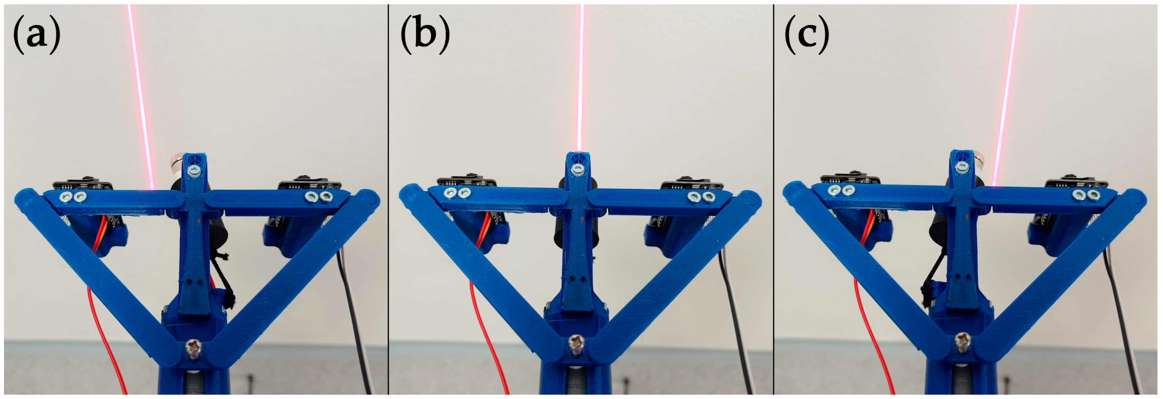
A component was attached to the front end to allow eccentric attachment of the elastic cord along with the laser projector mount. To perform the translation of the projected laser pattern during the digitization process, the user rotates the guide rod. When rotating clockwise, the projected laser pattern is shifted to the right, and when rotating counterclockwise, the laser pattern is shifted to the left. This can be observed in Figure 5. The laser is mounted in the laser projector holder, which is held in the front mount by screw M3. A hole is designed in the front bracket for a screw with a slightly larger diameter to allow the screw to rotate and not be firmly attached. PTFE tape was wound onto the screw to flatten the thread surface and reduce friction between the screw and the holder. A small spring was inserted between the laser projector mount and the front mount to ensure the screw head was pressed against the mount. Once the laser mount was assembled, a thin elastic string was tied to the eccentric component on the guide rod. Initially, a slotted mechanism was designed to rotate and move the laser projector, but the components were designed to be very thin, with a thickness of cca. 2 mm. Some of these parts could not be manufactured by FFF technology to the required quality and strength, and some were quickly broken when the mechanism was assembled. For this reason, an elastic cord was chosen to carry out the movement, as can be seen in Figure 6. Once the assembly was assembled, this solution performed the movement correctly. The use of an elastic string also has the advantage of dampening unwanted collisions of the laser projector with surrounding objects during the placement of the device within confined spaces.

Figure 5.
Representation of the movement of the laser line during digitizing. (a) Left position. (b) Center position. (c) Right position.

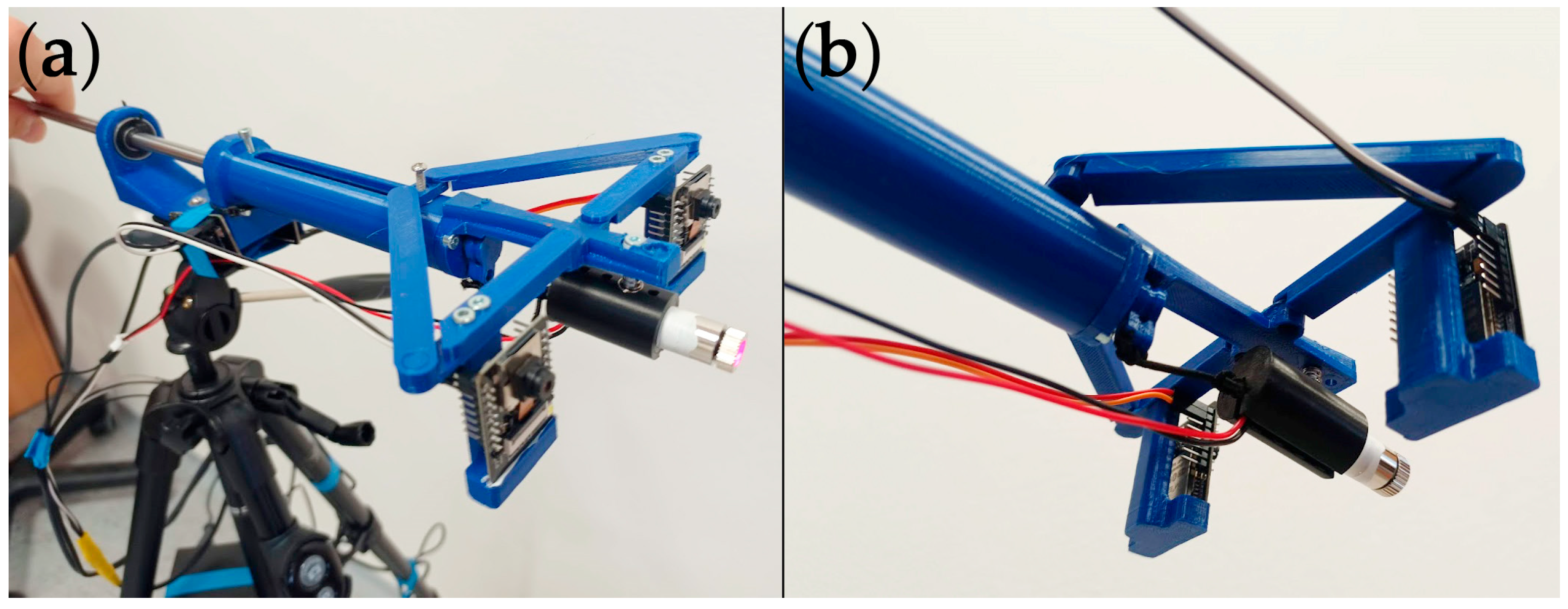
Figure 6.
Picture of prototype digitizing device. (a) At angle view. (b) At angle bottom view.
The prototype digitizing device can be placed on a tripod. The device is designed to be powered by portable external power source via USB interface. This makes the device portable and does not need power from the grid. As can be seen from the power consumption measurements of the devices, one ESP32-CAM device consumes 270 mA during high-power function when transmitting high-resolution video. During digitizing, only video images are captured, and the device consumes roughly half of this power. The laser projector is rated 10 mW, while consuming roughly 2 mA when powered at 5 V. The maximum theoretical consumption of the device is 560 mA. When powered by a portable external battery with a capacity of 20,000 mAh, it is theoretically possible to power the prototype digitizing device for about 36 h. In reality, the device consumes roughly half of the maximum power consumption, and therefore, it is possible to operate the device for roughly 70 h under ideal theoretical conditions. The prototype digitization device requires a connection to a computer, and it is possible to use a laptop computer with a battery and work in places without a main power source. It is also possible to connect the prototype device to a laptop with a wireless Wi-Fi connection, allowing complete portability of the device.
3. Results
For the proposed prototype device, software with a unique principle of calculating the coordinates of the digitized surface based on the registration of common image points in the rectified images in the digitization process was designed. The projected vertical laser line was chosen as the common features for registration.
Verification of the Functionality of the Prototype Digitization Device
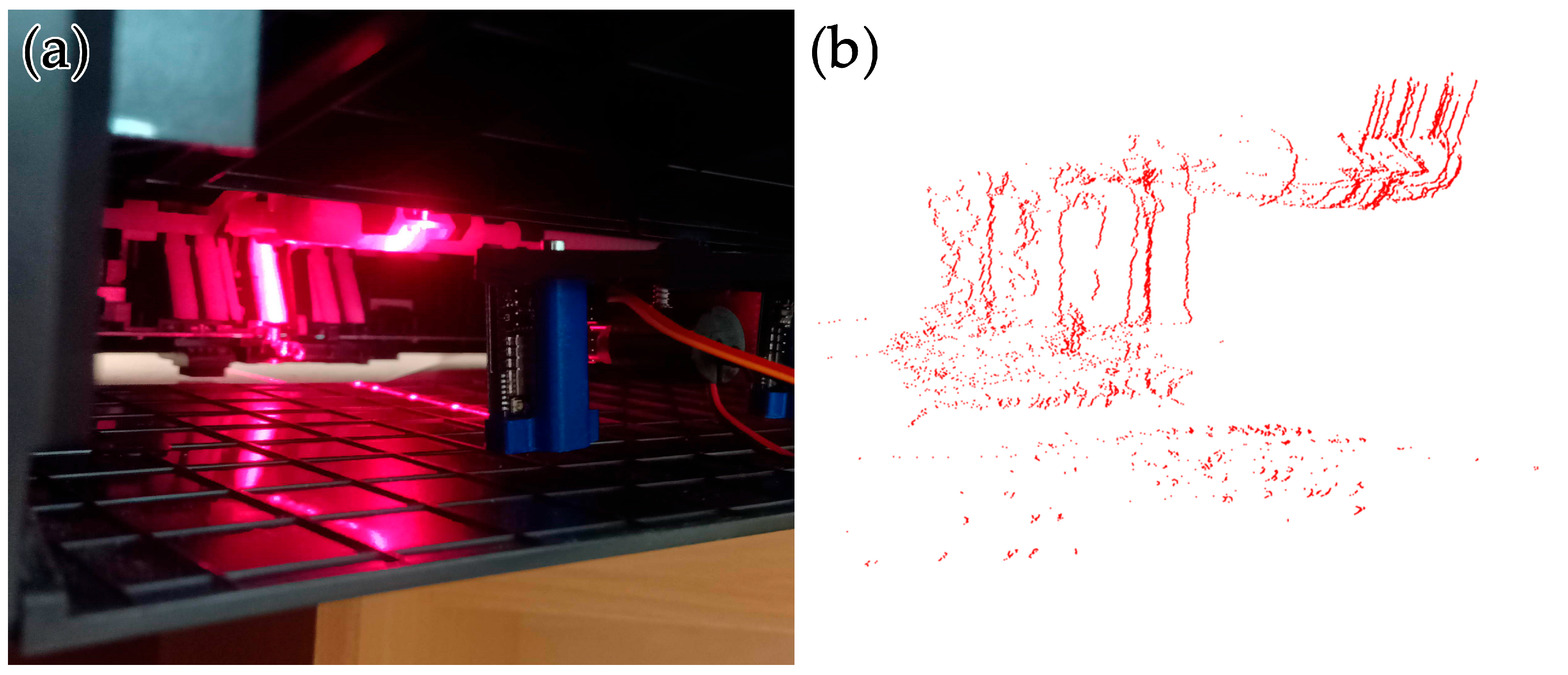
Experimental verification of the functionality of the prototype digitization device was subsequently required. The prototype digitization device was verified while digitizing the surface in confined spaces. For verifying the functionality in hard-to-reach areas, the digitizing printer paper slider was chosen. As can be observed in Figure 7a, the printer surface is black and glossy, and digitizing these surfaces is difficult, even when digitizing with industrial scanners, and often requires the application of a matte coating to the digitized surface. The prototype digitizing equipment was calibrated and then placed in the confined space of the printer’s paper feeder. Subsequently, surface digitization was performed. Despite the challenging surface for digitizing, the device was able to register the laser pattern projected on the surface, as can be observed in Figure 7b. The detail of the point cloud obtained by the prototype digitizing device depends on the number of individual scans performed.
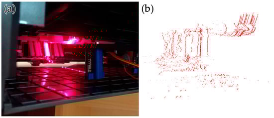
Figure 7.
Prototype digitization device during digitization of printer paper feeder. (a) Picture of device. (b) The resulting point cloud.
To verify the functionality of the prototype digitizing device, digitizing was performed in the engine compartment of the automobile in Figure 8. It is not possible to perform surface scanning in this area with conventional scanners because this area is dimensionally confined, and access is prevented by hoses and other components. Therefore, this space can be considered suitable for verifying the functionality of the prototype digitization device. After the calibration of the device was carried out freely in the area in front of the automobile, the device was adjusted to the position with the cameras folded down and inserted into the engine compartment. The actual insertion of the prototype digitizing device into this compartment was considerably challenging, as it was necessary to carefully insert the device into the compartment through hoses and other components, being careful to avoid unwanted collisions of the device with these components. With a strong impact or application of force, it would be possible to damage the ESP32-CAM equipment or the components of the equipment mechanism itself. Subsequently, the device was adjusted into position by the user during calibration by moving the arm holder to the front end position. Subsequently, a wooden bracket was attached to the motor section, and the device was secured to it with plastic tie wraps to prevent it from sliding.
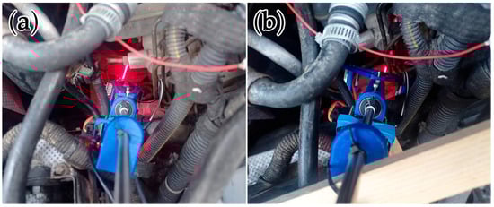
Figure 8.
Prototype digitization device inserted into the engine compartment area. (a) Folded position. (b) Position for digitizing.
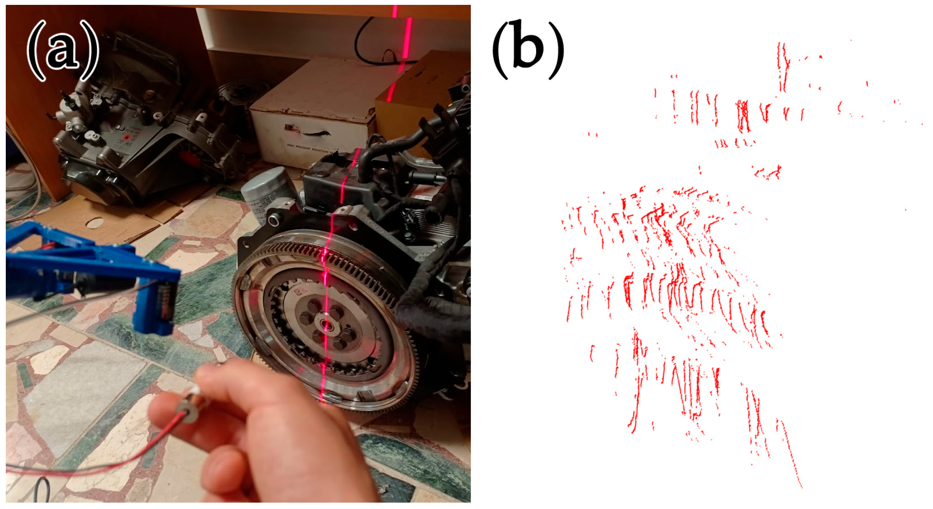
It was followed by a gradual digitization of the surface. After digitizing, the device had to be returned to the folded arm position, and the device was carefully removed. As can be seen in Figure 9, it was possible to clearly register the shapes and components digitized in the engine compartment of the automobile within the obtained point cloud. Considering the positive result of the digitization, it can be confirmed that the proposed prototype digitization device can be used in the digitization and technical diagnosis in the field of hard-to-reach areas.
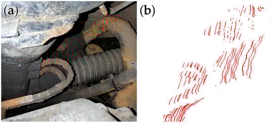
Figure 9.
Digitizing the engine compartment of an automobile. (a) Picture of the automobile engine compartment. (b) Resultant point cloud.
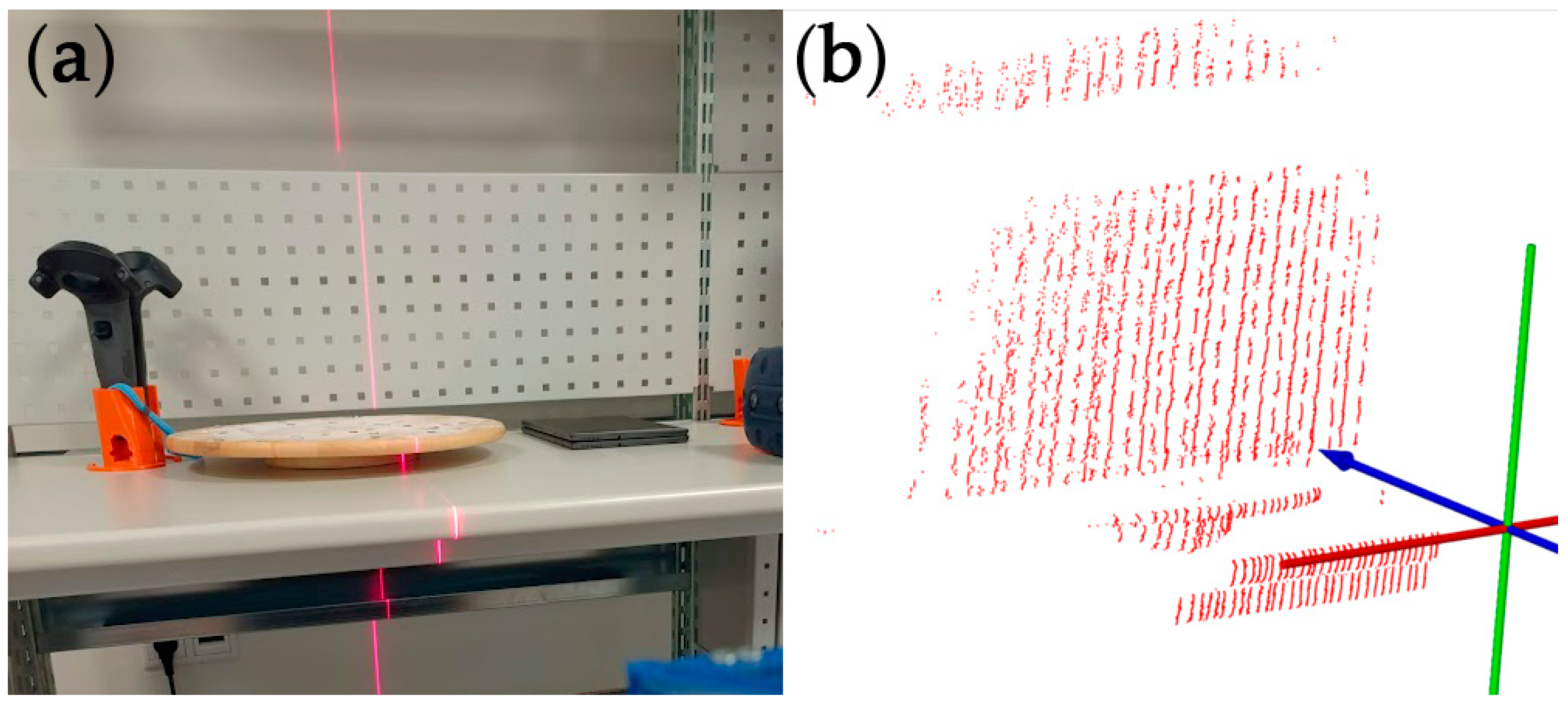
Furthermore, a workstation in the lab was digitized using the device as part of a testing of digitizing objects in the room. Despite the perforated surface of part of the wall, it was possible to digitize the workstation, as can be seen in Figure 10. This points to another possible use of the prototype digitizing device in the context of digitizing objects in the room.
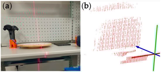
Figure 10.
Digitization of the workplace with prototype digitization device. (a) Picture of the workplace. (b) Resultant point cloud.
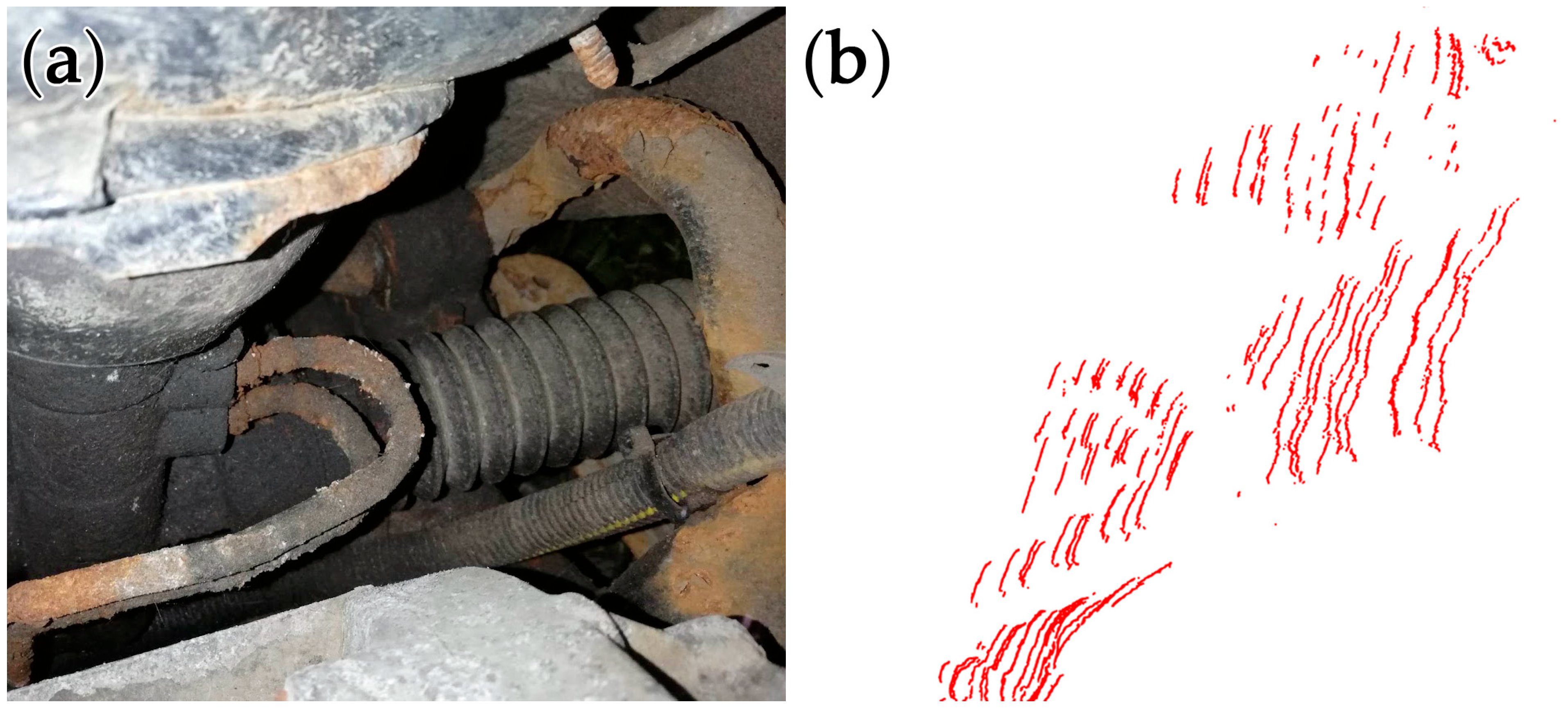
As the laser projector does not necessarily need to be mounted within the prototype digitization device, the user can orient the laser projector with their free hand. In this manner, it is possible to rotate the laser line at a slight angle or to focus more on digitizing a certain area in more detail. For this reason, the digitization of the engine part was carried out as in the previous digitization, but in this case, the user oriented the laser projector by hand. This can be observed in Figure 11. The digitization was successful, and further use of the prototype digitizing device can be proposed in which the user orients the laser projector with their free hand.
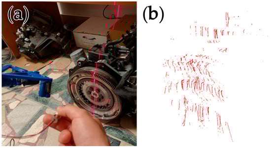
Figure 11.
Digitization of an automobile engine part. (a) Picture of pointing laser line by hand. (b) Resultant point cloud.
4. Discussion
As the proposed prototype solution is unique, the discussion aims to highlight the benefits for science and research and includes a proposal for future research. Among the benefits for science and research, several concepts for a prototype digitizing device can be proposed which are the result of a detailed analysis of the implementation of selected reverse engineering techniques. In this context, the selection of suitable hardware has been made within this research, and a design for the prototype digitization device has been proposed. One of the key aspects is the use of a projected laser pattern, which is used for explicit and accurate registration of common visual elements on the surface of the digitized object. Another important contribution of the work is the use of ESP32-CAM devices. These devices are beneficial because of their small size, relatively low cost, and low power consumption. These features allow for portability of the prototype digitizing device using external portable batteries. ESP32-CAM devices also allow for the replacement of optical sensors and lenses, the use of a flexible extension cable to connect the optical sensor to the motherboard, and the ability to connect to a computer using wireless technologies such as Bluetooth and Wi-Fi. Another advantage is the ability to connect multiple ESP32-CAM devices simultaneously without interfering with each other. As part of the work, physical models of the components of the prototype digitizing device assembly were created. FFF technology was used to produce them.
This work also includes the design of software for calibrating the device and calculating coordinates for surface scanning for prototype digitization device with a custom digitization principle based on stereovision and the use of laser line projection. The basic principle of the mechanism of the prototype digitization device was the movement of a linear bearing along a guide rod. The guide rod was mounted in two single-row ball bearings. An arm holder was attached to the linear bearing. After calibration, manual sliding of the linear bearing by the user adjusted the device to the position for insertion into the confined space. In this position, the cameras are tilted. Once the device was positioned, the device was manually adjusted by the user to the first position, and digitizing was performed. In the digitizing process, a projected laser line was moved across the surface by rotating the guide rod. After a sufficient number of calibrations had been performed, the user confirmed the completion of the digitization process, and the result was a stored point cloud.
The functionality of the prototype digitizing device was verified experimentally. The digitization of surfaces in hard-to-reach places was performed by digitizing the paper feeder within the printer and digitizing the surface in the engine compartment of an automobile. The digitization process was successful and resulted in a point cloud of the digitized area in hard-to-reach places. The main objective of the work can be considered to have been met. Subsequently, an experimental verification of functionality was conducted in the use of the prototype digitization device in the process of digitization of a part of the workbench in the laboratory and a part of the engine. These digitizations were successful, and thus, the use of the prototype digitizing device as an industrial scanner was verified. The free-hand orientation of the laser projector by the user was also verified successfully.
Future research may be focused on improving the design and mechanism for better use in diagnostics of hard-to-reach areas, as well as on the use of stepper motors for automatic mechanism movements. Another aspect may be to reduce size and weight and increase accuracy, while reducing the digitization error rate through the use of prototype digitization equipment. Further work is needed on debugging the software and adding features for digitizing error checking. The point cloud processing method may also be proposed for removing gross and systematic errors of digitization, merging point clouds from multiple digitizations, and designing suitable parameters of the surface polygonization process from the obtained point cloud. Adding a graphical user interface, a control panel with buttons, a representation of errors and calibration accuracy, a real-time display of the digitized surface and the current point cloud, and real-time control of adjustable internal camera parameters may be important additions. Future research may focus on the design of a desktop or portable prototype digitizing device for industrial use in digitizing physical objects. Implementing the use of external reference points for merging point clouds from multiple digitizations could enable sequential scanning of objects as the device is moved within a scene, providing accurate calculation of 3D coordinate points and synchronizing live streaming of two real-time images using ESP32-CAM devices, thus performing digitization from continuous surface scanning. Eventually, the use of structured light, multiple laser line projectors and a more precise laser projector with higher light intensity might be explored. Research could also focus on the accuracy and precision of the point cloud obtained from the prototype digitizing device under different lighting conditions, using different laser or other structured light projectors, with different external and internal device parameter settings, at different distances from the surface to be digitized, and using different optical sensors and lenses. Finally, future research may explore the use of the prototype digitization device in the automation and robotization of manufacturing processes, e.g., computer vision, and its use in the sensing of packages on a conveyor belt or robotic vision.
5. Conclusions
The proposed prototype solution addresses the problem of 3D surface scanning of physical objects in hard-to-reach areas. In contrast to the use of endoscopic cameras and 3D endoscopic devices, the proposed prototype technology provides a unique and novel way of surface digitization, taking advantage of available electronic modules and introducing a custom method of surface digitization without the need to use external reference points or to move the device while scanning the surface. In contrast to 2D endoscopic devices, it brings the possibility of obtaining information not only based on visual inspection but based on 3D measurements, which can be significant in the field of technical diagnostics of machines. The proposed prototype device allows one to digitize the 3D surface of objects in tight spaces and to obtain point clouds for subsequent polygonization of the surface model or to perform measurements in the scope of NDT. The current state of research on the device is limited by the use of manual movement for the moving parts of the device. Future research on the design of a prototype solution will be aimed at addressing these limitations and will focus on providing a detailed description of the unique software solution; subsequent improvement of the device using servo motors; evaluation of the accuracy, precision, and quality of the surface obtained using the device; and application of the device within a specific practical application.
Author Contributions
Conceptualization, A.V. and J.K.; methodology, M.K.; software, A.V.; validation, A.V. and M.K.; formal analysis, M.K.; investigation, A.V.; resources, M.K.; data curation, A.V.; writing—original draft preparation, A.V. and J.K.; writing—review and editing, A.V. and J.K.; visualization, A.V.; supervision, M.K.; project administration, A.V.; funding acquisition, M.K. All authors have read and agreed to the published version of the manuscript.
Funding
This research received no external funding.
Institutional Review Board Statement
Not applicable.
Informed Consent Statement
Not applicable.
Data Availability Statement
The datasets generated during the current study and analyzed during the current study are available from the corresponding author upon reasonable request.
Acknowledgments
This paper has been elaborated in the framework of the projects KEGA 002TUKE-4/2023 granted by the Ministry of Education, Research, Development and Youth of the Slovak Republic.
Conflicts of Interest
The authors declare no conflicts of interest.
Abbreviations
The following abbreviations are used in this manuscript:
| FFF | Fused filament fabrication |
| NDT | Non-destructive testing |
| CAD | Computer-aided design |
References
- Geng, J.; Xie, J. Review of 3-D Endoscopic Surface Imaging Techniques. IEEE Sens. J. 2014, 14, 945–960. [Google Scholar] [CrossRef]
- Yasuda, Y.D.V.; Cappabianco, F.A.M.; Martins, L.E.G.; Gripp, J.A.B. Aircraft Visual Inspection: A Systematic Literature Review. Comput. Ind. 2022, 141, 103695. [Google Scholar] [CrossRef]
- Blankschän, M.; Kanzler, D.; Liebich, R. Approaches to Assess Reliability in Visual Inspection. Insight-Non-Destr. Test. Cond. Monit. 2023, 65, 541–544. [Google Scholar] [CrossRef]
- Furukawa, R.; Kawasaki, H. Uncalibrated Multiple Image Stereo System with Arbitrarily Movable Camera and Projector for Wide Range Scanning. In Proceedings of the Fifth International Conference on 3-D Digital Imaging and Modeling (3DIM’05), Ottawa, ON, Canada, 13–16 June 2005; pp. 302–309. [Google Scholar]
- Furukawa, R.; Kawasaki, H. Self-Calibration of Multiple Laser Planes for 3D Scene Reconstruction. In Proceedings of the Third International Symposium on 3D Data Processing, Visualization, and Transmission (3DPVT’06), Chapel Hill, NC, USA, 14–16 June 2006; pp. 200–207. [Google Scholar]
- Nagakura, T.; Michida, T.; Hirao, M.; Kawahara, K.; Yamada, K. The Study of Three-Dimensional Measurement from an Endoscopic Images with Stereo Matching Method. In Proceedings of the 2006 World Automation Congress, Budapest, Hungary, 24–26 July 2006; pp. 1–4. [Google Scholar]
- Furukawa, R.; Kawasaki, H. Laser Range Scanner Based on Self-Calibration Techniques Using Coplanarities and Metric Constraints. Comput. Vis. Image Underst. 2009, 113, 1118–1129. [Google Scholar] [CrossRef]
- Aoki, H.; Furukawa, R.; Aoyama, M.; Hiura, S.; Asada, N.; Sagawa, R.; Kawasaki, H.; Tanaka, S.; Yoshida, S.; Sanomura, Y. Proposal on 3-D Endoscope by Using Grid-Based Active Stereo. Annu. Int. Conf. IEEE Eng. Med. Biol. Soc. 2013, 2013, 5694–5697. [Google Scholar] [CrossRef]
- Furukawa, R.; Aoyama, M.; Hiura, S.; Aoki, H.; Kominami, Y.; Sanomura, Y.; Yoshida, S.; Tanaka, S.; Sagawa, R.; Kawasaki, H. Calibration of a 3D Endoscopic System Based on Active Stereo Method for Shape Measurement of Biological Tissues and Specimen. Annu. Int. Conf. IEEE Eng. Med. Biol. Soc. 2014, 2014, 4991–4994. [Google Scholar] [CrossRef] [PubMed]
- Furukawa, R.; Masutani, R.; Miyazaki, D.; Baba, M.; Hiura, S.; Visentini-Scarzanella, M.; Morinaga, H.; Kawasaki, H.; Sagawa, R. 2-DOF Auto-Calibration for a 3D Endoscope System Based on Active Stereo. Annu. Int. Conf. IEEE Eng. Med. Biol. Soc. 2015, 2015, 7937–7941. [Google Scholar] [CrossRef]
- Furukawa, R.; Oka, S.; Kotachi, T.; Okamoto, Y.; Tanaka, S.; Sagawa, R.; Kawasaki, H. Fully Auto-Calibrated Active-Stereo-Based 3D Endoscopic System Using Correspondence Estimation with Graph Convolutional Network. Annu. Int. Conf. IEEE Eng. Med. Biol. Soc. 2020, 2020, 4357–4360. [Google Scholar] [CrossRef] [PubMed]
- Peta, K.; Stemp, W.J.; Chen, R.; Love, G.; Brown, C.A. Multiscale Characterizations of Topographic Measurements on Lithic Materials and Microwear Using a GelSight Max: Investigating Potential Archaeological Applications. J. Archaeol. Sci. Rep. 2024, 57, 104637. [Google Scholar] [CrossRef]
- Aust, J.; Pons, D. Comparative Analysis of Human Operators and Advanced Technologies in the Visual Inspection of Aero Engine Blades. Appl. Sci. 2022, 12, 2250. [Google Scholar] [CrossRef]
- Richter, A.; Steinmann, T.; Rosenthal, J.-C.; Rupitsch, S.J. Advances in Real-Time 3D Reconstruction for Medical Endoscopy. J. Imaging 2024, 10, 120. [Google Scholar] [CrossRef] [PubMed]
- Turygin, A.; Mosyurchak, A.; Zhalo, M.; Hammer, M. Maintenance and Technical Diagnostics of Machines. MM Sci. J. 2016, 2016, 1491–1496. [Google Scholar] [CrossRef]
- Gupta, M.; Khan, M.A.; Butola, R.; Singari, R.M. Advances in Applications of Non-Destructive Testing (NDT): A Review. Adv. Mater. Process. Technol. 2022, 8, 2286–2307. [Google Scholar] [CrossRef]
- Zhang, Z.; Wang, W.; Tian, X.; Luo, C.; Tan, J. Visual Inspection System for Crack Defects in Metal Pipes. Multimed. Tools Appl. 2024, 83, 81877–81894. [Google Scholar] [CrossRef]
- OpenCV—Open Computer Vision Library. Available online: https://opencv.org/ (accessed on 27 January 2025).


Disclaimer/Publisher’s Note: The statements, opinions and data contained in all publications are solely those of the individual author(s) and contributor(s) and not of MDPI and/or the editor(s). MDPI and/or the editor(s) disclaim responsibility for any injury to people or property resulting from any ideas, methods, instructions or products referred to in the content. |
© 2025 by the authors. Licensee MDPI, Basel, Switzerland. This article is an open access article distributed under the terms and conditions of the Creative Commons Attribution (CC BY) license (https://creativecommons.org/licenses/by/4.0/).