Article

Implementing an Industry 4.0 UWB-Based Real-Time Locating System for Optimized Tracking

by
Athanasios Sidiropoulos
1,
Dimitrios Bechtsis
2 and
Dimitrios Vlachos
1,*
1
Laboratory of Statistics and Quantitative Analysis Methods (LASCM), Department of Industrial Management, School of Mechanical Engineering, Aristotle University of Thessaloniki (AUTH), 54124 Thessaloniki, Greece
2
Department of Industrial Engineering and Management, International Hellenic University, 57001 Thessaloniki, Greece
*
Author to whom correspondence should be addressed.
Appl. Sci. 2025, 15(5), 2689; https://doi.org/10.3390/app15052689
Submission received: 20 December 2024 / Revised: 11 February 2025 / Accepted: 27 February 2025 / Published: 3 March 2025

Abstract

:
The Internet of Things (IoT) provides technical solutions for monitoring assets in facility layouts, and this is further strengthened by the development of sophisticated software tools for intralogistics operations. The present research provides a taxonomy for the existing tracking technologies and a comparison matrix for supporting decision making when selecting the most suitable technology for real-time tracking in indoor areas. Although numerous tracking technologies exist, ultra-wideband (UWB) technology has gained significant attention in recent years due to its exceptional positioning accuracy and its ability to operate effectively in challenging environments with numerous obstacles, even under non-line-of-sight (NLOS) conditions. Specifically, this research focuses on a real-time location system (RTLS) that is designed and implemented to monitor assets based on UWB technology. Additionally, a new algorithm is introduced to reduce localization errors by attempting to exclude NLOS measurements from the tag’s position calculations. The experiments showcased that the proposed algorithm improves the overall positioning error by 24%, reporting an RMSE of 0.124 m in comparison to the 0.163 m of the normal trilateration method. The experimental results highlight the efficiency of the proposed solution for fast and accurate localization and tracking in real-world environments.

1. Introduction

Industry 4.0 makes significant use of information and automation technologies. The integration of information technology (IT), artificial intelligence (AI), machine learning (ML) and data analytics has paved the way for a virtual environment that is called digital-twin (DT) and monitors real-world facilities [1]. The Industrial Internet of Things (IIoT) proposes the implementation of new technologies to industries and suggests that the IIoT should not merely function to enable autonomous production but also promote the use of real-time information for employees, machines, and software tools within the industry, and even communicate with external stakeholders [2,3]. A comprehensive analysis of how digitization and automation could impact the construction industry (involving companies, the environment, and employees) has been conducted, and the results showcased that it can positively affect operational cost savings, time savings, safety enhancement, sustainability, collaboration, and on-time delivery [4]. Others conclude that there is not only one respect in which Industry 4.0 and smart manufacturing can transform industries. Some experts are convinced that it will transform the existing industries significantly; others argue that Industry 4.0 is just a collective term for technologies and concepts that have been known and applied for quite some time [5]. Either way, we are living in an era of advanced technology, and the need for real-time information about industrial processes and real-time asset monitoring is growing every day. Transparency and the cyber-physical system interconnections must be enhanced as a first step to the digital transformation. The widespread use of location-based services requires accurate positioning information about assets in both indoor and outdoor facilities. In an outdoor environment, global navigation satellite systems (GNSSs) effectively provide position information with high accuracy; they are widely employed as personal navigation devices using a smartphone. Unfortunately, due to the signal attenuation caused by buildings and the surrounding materials, GNSS cannot be used to provide location-based information in indoor environments. Therefore, indoor positioning systems (IPSs) are designed to provide a solution to this technological limitation.
An IPS is a network of devices and services that can locate resources in indoor facilities, while the term real-time locating system (RTLS) refers to the ability of an IPS to track resources in real-time and at the same time present them to the end users. There are plenty of applications for RTLS in indoor areas. Researchers proposed an RTLS architecture that could track assets and improve safety conditions, and the results showed that the implemented systems can reduce the risk of construction site accidents with low capital and low operational costs [6,7]. Others have proposed using RTLS for road-worker safety when workers leave the safe zone [8]. Another study emphasizes the application of RTLS for progress assessments on construction sites, enabling project managers to monitor progress remotely [9], while others used a UWB RTLS to estimate individual disease transmission rates in indoor social events. By analyzing contact intensity, duration, and proximity, the study offers precise transmission risk assessments and valuable insights for improving infectious disease modeling and public health strategies [10]. The integration of ultra-wideband (UWB) technology in the latest iOS and Android devices reflects growing interest, and this technology is anticipated to see widespread use in the coming years, improving user experience with indoor tracking in malls, airports, and large indoor spaces.
It should be stated that there are three major RTLS categories: (i) wireless signal tracking; (ii) visible tracking; and (iii) pedestrian dead reckoning (PDR) tracking. Multiple RTLS implementations have been proposed using state-of-the-art technologies. The main wireless tracking technologies are: (i) ultrasound; (ii) Bluetooth; (iii) Wi-Fi; (iv) dual-band Wi-Fi that calculates the position of the tag based on received signal strength identification (RSSI) measurements from both the 2.4 GHz and 5 GHz bands; (v) radio frequency identification (RFID); and (vi) ultra-wideband technology. The main visible tracking technologies are: (i) visible light tracking and (ii) image recognition. The main PDR tracking technology is the inertial measurement unit (IMU). Each of the above-mentioned technologies has strengths and limitations; this has led to many RTLS variations. To this end, a systematic categorization of the above-mentioned technologies is presented in Section 2; it classifies the technologies employed based on their technical specifications. This categorization aims to address the question of which technology is best suited for a particular application based on the following criteria: required range, positioning accuracy, LOS/NLOS impact, computation complexity, and cost.
RTLS implementations can be classified based on tracking conditions into line-of-sight (LOS) and non-line-of-sight (NLOS) varieties. In NLOS conditions, there is no direct visual contact between the transmitter and receiver, whereas LOS conditions involve a clear, unobstructed path for communication. The term “visual contact” is primarily relevant for visible tracking systems, where the objects to be tracked must remain within the system’s field of view. In the case of wireless signal tracking, it refers to the presence of a direct signal path between the transmitter and receiver. Technologies within the wireless signal and pedestrian dead reckoning (PDR) tracking categories are capable of functioning under NLOS conditions, while visible tracking systems are limited to LOS conditions.
Despite the advancements in UWB-based RTLS, challenges such as cost-efficiency, scalability, and accurate localization in NLOS scenarios persist. This study addresses these gaps by introducing an optimized algorithm to minimize the impact of NLOS by attempting to exclude NLOS measurements from the tag’s position calculation; it also introduces a method that needs only two anchors to calculate the tag’s position. The experiments showcase that the proposed algorithm improves the positioning error when there is an NLOS range measurement in one of the three ranges, achieving accuracy comparable to the system’s performance at LOS points. The innovation of this approach lies in its ability to sustain high positioning accuracy in environments with numerous obstacles and limited LOS measurements. Furthermore, it can be utilized in various positioning algorithms as a fallback solution when the NLOS range correction is ineffective. The proposed RTLS implementation uses IoT hardware devices and wireless signals based on UWB technology to track objects around an industrial facility layout. With respect to the software layer, open-source software libraries were employed for the development of the application programming interface (API). The developed tool relies on the IoT backbone mechanism for the real-time logging of intralogistics and implements a user-friendly interface that: (i) monitors the assets in real time; (ii) stores their locations; (iii) calculates the total distance travelled; and (iv) tracks and stores the exact path followed.
The rest of the paper is structured as follows. The Literature Review (Section 2) analyzes the technological background of RTLS implementations and provides a technological comparison; the state-of-the-art RTLS solutions are also discussed. Section 3 presents the tracking methods, the proposed localization algorithm, and the developed RTLS. Section 4 presents the results of the developed RTLS system. Finally, the conclusions are given in Section 5.

2. Literature Review

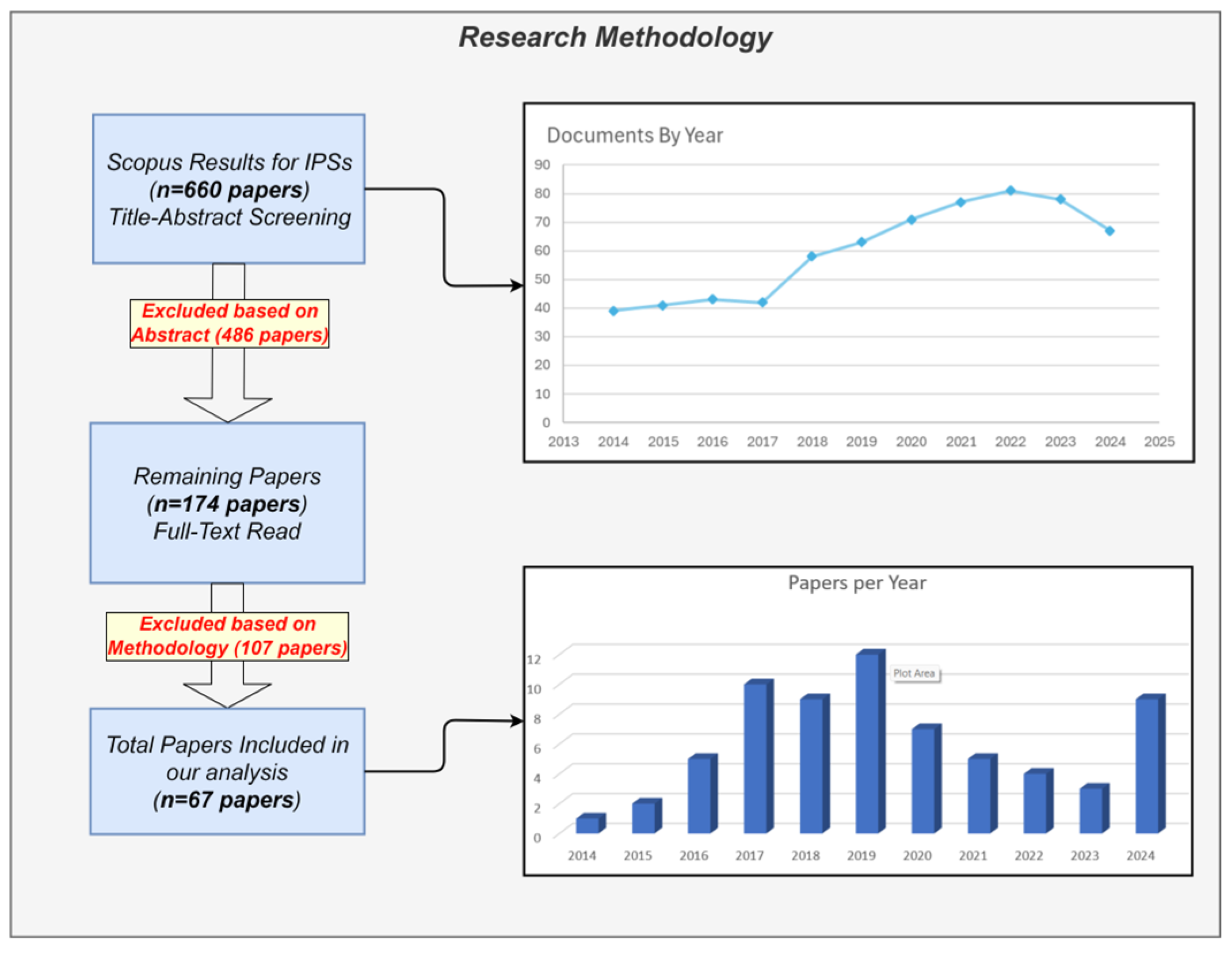
2.1. Research Methodology

A systematic literature review of indoor positioning systems and techniques was carried out (Figure 1). Scopus was used as the main scientific database in which the terms “indoor positioning system” and “real time locating system” were included as keywords. Initially, 660 papers/articles were found and, after title and abstract screening, 486 paper were excluded as irrelevant. Then, 107 papers out of the remaining 174 were excluded after a full text read, because they focus on different researching fields. Finally, an extended year-wise analysis was conducted in two phases: (i) the relevant papers found on Scopus with RTLS and IPS keywords; and (ii) the papers that we selected after a full-text read and that focused on our research field.
The first conclusion of this analysis concerns the research interest in using UWB and Wi-Fi technologies (Figure 2) for real-time indoor tracking applications. Wi-Fi is a set of wireless network protocols, based on the IEEE 802.11 family of standards for local networks. The new generation of dual Band Wi-Fi shows increased accuracy in distance measuring, which has led to new IPS approaches based on both Wi-Fi versions. This is because dual-band Wi-Fi typically provides more accurate position estimations than single-band systems by merging the extended range of the 2.4 GHz band with the higher precision of the 5 GHz band. This combination of frequencies helps reduce errors from interference, multipath effects, and signal fading. On the other hand, UWB is considered a more suitable solution due to its immunity to signal attenuation in numerous (metallic and non-metallic) materials and because it provides more accurate distance measurements. Figure 2 also shows that, since 2017, UWB technology has been the dominant method for IPS for two fundamental reasons: (i) its high positioning accuracy due to the bandwidth range advantage; and (ii) the implementation cost has significantly decreased over the years due to the availability of more affordable UWB hardware.

2.2. Related Works

The main direction of RTLS-related research concerns the development of more accurate systems based on existing technologies. Thus, few studies compare the RTLS implementations of different technologies [11,12]. Other studies have contributed to the improvement of: (i) the Wi-Fi method, using different strategies [13,14,15]; (ii) the object localization accuracy on multifloored structures [16]; and (iii) distance measurements, using neural networks to predict positions more accurately [17]. On the other hand, some studies introduce the UWB signal technology for real-time tracking in different environments and analyzed the system’s performance [18,19,20]. Moreover, others proposed a positioning estimation technique based on particle filtering, which is applied to distance measurements in order to improve the overall system’s performance [21]. In other cases, researchers proposed combining technologies based on UWB and IMU, as the integrated application could locate assets with better accuracy when IMU and UWB were cooperatively used. For example, in a recent study, positioning accuracy was improved using a Variable Noise Variance (VNV) Kalman filter that fuses data from the UWB, IMU, and magnetometer sensors [22]. As the system cost was high, a low-cost and high-accuracy Wi-Fi solution was also proposed using an Unscented Kalman filter (UKF) to improve the tracking accuracy of the Wi-Fi [23]. Moreover, RTLS implementations have been proposed for safety and body posture monitoring purposes in indoor environments. In this regard, some researchers tried to use UWB technology to develop a system for underground positioning and collision avoidance [24]. Furthermore, a system based on IR-UWB for human localization and the tracking of human body limb movements in 3D for healthcare applications was proposed, with a system error lower than 3 cm for 90% of the measurements [25]. In more recent research, an RTLS based on UWB technology was used to track lambs and their movement in an indoor barn [26]. The above literature review highlights the increased research interest in RTLSs and, specifically, in the use of UWB technology for tracking purposes.
A technology that is widely used for RTLS is RFID; this emerging technology enables the mobility tracking of objects and humans. There are three main types of RFID systems: (i) passive [27]; (ii) semi-passive; and (iii) active systems. A typical RFID system contains tags (also referred to as transponders, smart tags, smart labels, or radio barcodes), a reader (also called a writer, decoder, interrogator, transmitter, receiver, or transceiver), and a host computer. A comparative analysis between low-frequency RFID (LF-RFID), ultra-high-frequency RFID (UHF-RFID) and UWB IPSs showed that the UWB system was more accurate than the RFID systems, with a mean error of 0.58 m compared to 1.53 m and 3.78 m for the LF-RFID and UHF-RFID systems, respectively [28]. For an alternate solution, the RFID tag devices were placed in the position of the anchor devices. Thus, to track an object, the object was equipped with an RFID reader while many RFID tags were placed in the industrial facility. The biggest shortfall of the proposed system was the small coverage area. After the experiments, the researchers concluded that the proposed system needed many tags to achieve small localization errors, which results in high costs for large coverage areas [29].
Ultrasound-based implementations for an RTLS can provide position tracking with an accuracy of 1–3 cm. Ultrasound waves are sound waves with frequencies higher than the upper audible limit of human hearing. For experimental purposes, a custom ultrasound RTLS was designed in LOS conditions [30]. In the implemented system, the tag transmits a signal and waits to receive a response signal from each anchor. The time of flight (TOF) method calculates the distance from each anchor and, using a trilateration algorithm, it calculates the tag’s position. In all the tests, the average error was less than 1 cm; this indicates that ultrasound technology can reach even sub-centimeter accuracy. However, ultrasound technology has the drawback of a limited range (up to 10 m); additionally, it cannot be applied in environments with solid obstacles (walls, solid objects, metallic objects etc.) as it does not work under NLOS conditions.
Other well-known RTLS technologies are visible light tracking and image recognition. An RTLS based on visible light communication (VLC) used genetic algorithms (GA) to track assets, with particularly satisfactory results in accuracy (position error below 5 cm) [31]. Others proposed an RTLS with augmented reality; this study used a smartphone with an embedded camera to locate the user’s position and guide him in an indoor environment [32]. This system can locate the user with a low position error (some centimeters), but it works only in LOS conditions, and even a small obstacle can prevent the tag’s tracking. Another approach for tracking unmanned grounded vehicles (UGVs) indoors with the use of cameras has been proposed; it could detect UGVs with sub-centimeter position accuracy [33].
Bluetooth is another technology which is used in RTLS implementations, employing the RSSI method to calculate the position of the tag. Unfortunately, Bluetooth has a short coverage distance (about 10 m) and many devices are needed to cover the whole indoor area. Furthermore, the accuracy of this method is about 1–5 m, which significantly limits its industrial use. Several researchers have tried to increase its accuracy by using alternative techniques. To this end, an RTLS implementation based on Bluetooth v4.2 on an Apple iPhone 5s device was proposed. The researchers conducted two experiments, using three and then four beacons, placed in two different ways. The overall average error in this experiment was calculated to be 0.77 m [34]. Moreover, an analysis of the tracking accuracy of the new version of Bluetooth, 5.1, has been conducted, and the average error was 0.7 m [35]. Another RTLS based on Bluetooth low-energy beacons showed that the error decreases for short beacon–smartphone distances; it was concluded that numerous beacons should be used in indoor environments in order to achieve a low positioning error [36]. Furthermore, an additional RTLS based on Bluetooth technology and the RSSI method with an accelerometer and a barometer was proposed, and the estimated position error was about 1.95 m, which is still not appropriate for industrial applications [37].
In the case of the Wi-Fi RTLSs, the total accuracy is still at a very low level. The main advantage of Wi-Fi technology is that it does not need extra hardware appliances as it can be based on existing Wi-Fi routers. Some researchers tried to implement a Wi-Fi-based RTLS for real-world construction and, based on their experiment, the positioning system’s accuracy has an average error of 5 m [38]. Furthermore, a Wi-Fi RTLS based on a deep neural network called WiDeep had an average accuracy of 2.64 m and 1.21 m in large and small environments, respectively [39]. Due to the increased error levels, a RTLS based on dual-band Wi-Fi at 2.4 and the 5 Ghz bands was proposed; the researchers concluded that this method provides better results (a mean distance error of 1.7 m) compared to the single Wi-Fi band (a mean distance error of 3–5 m), but it needs multiple dual band access points [40]. Even in cases where the Wi-Fi technology is combined with other state-of-the-art technologies such as geo-magnetism, the errors in the measurements were still high [41]. Additionally, research that aims to increase Wi-Fi position error has been published by using CNNs, and the mean error was still over 3 m (3.5 m mean error and 5.1 m 75th percentile) [42].
Another technique based on Wi-Fi technology is the fine-time measurement (FTM) round-trip time (RTT). This technique uses the IEEE 802.11mc protocol incorporated in IEEE 802.11-2016, which allows computing devices to measure the distance to nearby Wi-Fi access points (APs) and determine their indoor location with a precision of 1–2 m [43]. In 2D ranging tests in a recent study, an average root mean square error (RMSE) of 1.1 m was accomplished [44]. In another study, a new method was proposed that reduces the positioning RMSE error to 0.79 m [45]. Another study demonstrated that the Wi-Fi FTM RTT technique can be utilized in outdoor areas surrounded by buildings with available access points (AP), providing more accurate smartphone localization than GNSS [46].

2.3. Ultra-WideBand Technology

UWB technology has spread widely in the research community in recent years; it is used for both outdoor and indoor localization systems. UWB is a radio technology that has low energy consumption for short-range, high-bandwidth communications over a large portion of the radio spectrum. State-of-the-art UWB applications focus on sensor data collection, precision locating, and tracking. A recent study highlights that the global uncertainty of RTLS location systems based on UWB technology when the tag position errors are not corrected is estimated to be 0.35 m [47]. At the laboratory level (TRL 4 technology validated in the lab), numerous UWB studies have analyzed the performance of UWB radio ranging and positioning systems. Numerous commercial UWB kits are available for research labs and engineering teams nowadays, such as Decawave (which was acquired by Qorvo [48]), BeSpoon (which was acquired by STMicroelectronics, Geneva, Switzerland), Ubisense [49], SEWIO [50], etc. A comparison between Decawave and BeSpoon UWB RTLSs in LOS and NLOS conditions concluded that Decawave has lower positioning error but at a slightly smaller range than BeSpoon in NLOS conditions. Ultimately, the overall difference in performance of these modules is negligible [51]. Furthermore, a comparative experiment between the Ubisense, BeSpoon and Decawave UWB modules was conducted [52]. The evaluation took place in an NLOS environment that simulates an industrial warehouse with diverse equipment (robots, vehicle, railways, etc.), which perturbates UWB radio propagation and increases the positioning error. Under these conditions, the performance of the Decawave system was slightly better than that of BeSpoon and significantly more reliable than the Ubisense system. A multi-channel UWB system was proposed, and it was concluded that it was able to reduce the RMSE by 0.1 m compared to single-channel UWB systems [53]. Another comparison between the cheap DWM3000EVB and the expensive OptiTrack system [54] was executed without significant differences in localization accuracy [55]. Additionally, a custom UWB system based on a dynamic algorithm was proposed; it was able to localize assets with an error lower than 10 cm [56]. The minimal localization error enabled the application of UWB RTLS systems in more demanding scenarios, such as UAV landing assistance systems [57]. Finally, a novel collaborative localization method for UWB massive multiple input multiple output (MIMO) systems, named UWB-CollLoc, was proposed. This method addressed the challenges of anchor placement, communication reliability, and NLOS issues, employing Smart Crow Search Optimization (SCSO) for the anchor placement, a lightweight attention network (LAN) for identifying LOS and NLOS paths, and a semi-distributed approach combining the time difference of arrival (TDoA) and angle of arrival (AoA) for accurate localization. The experimental results demonstrate superior performance in terms of localization accuracy, efficiency, and reduced deployment costs compared to existing approaches [58].
The recent years, more sophisticated methods to increase the localization accuracy and minimize the NLOS impact have been proposed. A recent study evaluated the localization accuracy of a UWB kit using the DWM1000 module with 0, 1, 2, 3, and 4 biased anchors, resulting in 2D position accuracies of 0.05 m, 0.09 m, 0.15 m, 0.58 m, and 0.49 m, respectively; this shows that even one biased NLOS range affects the localization accuracy dramatically [59]. Similarly, a study utilizing generative adversarial networks (GANs) for data augmentation and a convolutional neural network (CNN) for LOS/NLOS classification demonstrated an average positioning error of 0.54 m [60]. A denoising neural network for enhanced UWB ranging was proposed to predict the ranging error. The proposed method was able to reduce the prediction error of the ranging distance by approximately 34.44% compared to the existing AI regression method, resulting in improved UWB positioning accuracy with an average positioning error of 0.20 m in seven different environments [61]. Another study examined the use of bias and deviation-weighted graph searches for NLOS calibration. The results demonstrate that the proposed algorithm has an average bias positioning error of 0.077 m under LOS conditions [62]. The limitation of this method is that environmental changes, such as the addition of more racks or large machines, necessitate system recalibration (i.e., the calculation of a new deviation-weighted graph of the new area).
Finally, in the literature, we identified methods that combine some of the already referenced methods and technologies. For example, one group of researchers tried to create an RTLS with a combination of a UWB module and an IMU sensor [63]. The study also examined the MPU-9250 sensor positioning error with the DWM1000 trilateration positioning error. The IMU sensor’s error is lower than the DWM1000 module’s error. However, the IMU calculates tag’s position based on acceleration and rotation measurements, and this results in an increase in the positioning error as time passes. The positioning accuracy of the approach that combines UWB with IMU outperforms (by 2.5 to 5 times) the approach using UWB sensors alone. Moreover, research on the PDR tracking category has been conducted on a multi-floor area with the use of a backtracking particle filter, and the mean error from these experiments was 1.6 m [64]. Furthermore, some researchers have tried to improve the UWB RTLS accuracy by applying a ray-tracing algorithm; they observed that the overall RMSE was below 0.25 m on every axis [65]. A similar approach has been studied to track shopping carts using a system based on UWB and IMU measurements, with an overall positioning error of 0.28 m [66]. Similarly, some researchers created a system based on UWB and IMU for ice hockey analytics; the 90th percentile error was smaller than 35 cm [67]. All the above studies highlight the increased research interest in using UWB technology for indoor tracking.
Table 1 provides an overview of the RTLS technologies analyzed, highlighting their strengths and limitations. The “Accuracy” column indicates the overall precision of the tracking technology, where low, mid, and high correspond to accuracies of several meters, centimeters, and millimeters, respectively. The “Range” column specifies the maximum distance between the anchor and the tag, with low, mid, and high representing ranges of several centimeters, meters, and tens of meters, respectively. The “Complexity” and “Cost” columns pertain to the overall system requirements. Lastly, the “LOS/NLOS Impact” column identifies how NLOS conditions affect the accuracy of each technology.
For each technology, the system processes data streams to determine the precise position of a moving object. The method used to process these data streams varies by technology and implementation, influencing the system’s complexity. Low, mid, and high represent the estimated processing power required to calculate the tag’s position. The estimated system cost reflects the expense per square meter for acquiring, installing, and operating the necessary hardware. Finally, the LOS/NLOS impact is categorized as low, mid, or high, indicating whether NLOS conditions affect accuracy minimally, moderately, or significantly. A dash signifies that the technology cannot localize the moving object under NLOS conditions.

2.4. Categorization of Existing Research Efforts

Table 2 presents the RTLS Technology Categorization Scheme. The papers are categorized based on: (i) their type (review papers for IPS and RTLS technologies, technology comparison papers that compare two or more technologies, and system architecture papers and application papers); and (ii) the technology that is introduced (UWB technology for high-spectrum low-energy signals based on IEEE 802.15.4 protocol, Bluetooth technology, which is a wireless technology based on IEEE 802.15.1 protocol, ultrasound that uses low-frequency signals, Wi-Fi that uses a wireless protocol based on the IEEE 802.11, IMU devices that measure and report a body’s specific force, angular rate, and sometimes the orientation of the body, RFID technology that uses electromagnetic fields to automatically identify and track tags, and visual tracking that uses computer vision to track objects). According to the technology categorization scheme, most of them implement and propose a system for indoor tracking by deploying an IPS based on one of the above-mentioned technologies.

3. Materials and Methods

3.1. Tracking Methods

For each solution based on the above-mentioned technologies, a specific methodology estimates the exact position of the assets. To locate a specific object, a tag is attached to it, and, in accordance with the selected technological category (wireless, vision, and PDR tracking), the implemented technology provides an estimation of the object’s position.
In the case of wireless signals, the methodologies used to track the object are analyzed below:
  • Angle of arrival (AoA). The AOA method estimates the position location by means of angular direction observations measured with respect to a reference axis using directional antennas or antenna arrays.
  • Time difference of arrival (TDoA). The TDoA method locates a signal source from the different arrival times at the receivers. Once the signal is received at two reference points, the difference in the arrival time can be used to calculate the difference in distances between the target and the two reference points. This difference can be calculated using the equation ∆x = c × (∆t), where c is the speed of light and ∆t is the difference in arrival times at each reference point. To obtain a true Δt measurement, the transmitter and receiver must be synchronized. An implementation based on this technique with unsynchronized devices has been proposed [68], and it was able to calculate the position of the object with an increasing computational cost.
Table 2. RTLS technology categorization scheme.
AuthorsTracking TechnologyManuscript Content
UWBBLΕUltrasoundWi-FiIMURFIDVisual TrackingReviewTechnology
Comparison
System Architecture-
Application
Jimenez A.R., Seco F., 2016 [51]
Gharat V., et al., 2017 [28]
Hyun J., et al, 2019 [65]
Yao L., et al., 2017 [63]
Yadar R., 2018 [32]
Athikulwongse K., et al., 2018 [69]
Chen H., et al., 2017 [31]
Jimenez A.R., et al., 2017 [52]
Astafiev A., et al., 2019 [36]
Karlsson F., et al., 2015 [40]
Diallo Al., et al., 2019 [29]
Jun Qi et al., 2017 [30]
Duong N. S., et al., 2018 [34]
Jeon J., et al., 2015 [37]
Haryanto D., et al., 2018 [41]
Woo S., et al., 2011 [38]
Abbas M., et al., 2019 [39]
Alarifi A., et al., 2016 [70]
Kunhoth J.., et al., 2020 [71]
Yassin A., et al., 2017 [72]
Oesterreich T.D, Osnabrück F.T., 2016 [4]
Kanan R., et al., 2018 [7]
Zhao Z., et al., 2021 [6]
De Angelis G.., et al., 2016 [21]
Ridolfi M., et al., 2018 [18]
Kumler J., et al., 2017 [19]
Yoon Paul K. et al., 2017 [73]
Witrisal Klaus et al., 2016 [20]
Bharadwaj R., et al., 2017 [25]
Yu J., et al., 2019 [23]
Li S., et al., 2019 [14]
Luo J., et al., 2019 [16]
Zourmand A., et al., 2019 [13]
Sadowski S., Spachos P., 2019 [11]
Zhang W., et al., 2019 [15]
Chen J., et al., 2019 [12]
Hoang, M., et al., 2019 [17]
Kianfar A. et al., 2020, [24]
Pérez-Solano J., et al., 2020 [68]
Grasso P., Innocente M., 2020 [74]
Simedroni R. et al., 2020 [75]
Guo S., et al., 2020 [22]
Bing W., et al., 2018 [56]
Schroeer G., 2018 [53]
Martínez del Horno J.., et al., 2021 [76]
Truong Q., et al., 2021 [77]
Vleugels R., et al., 2021 [67]
Hernánde, N., et al., 2021 [42]
Chen, W., 2021 [78]
Woods J., et al., 2024 [26]
Shamsollahi D., et al., 2024 [9]
Thota R., 2024 [10]
Yuxuan Z., Manyi. W., 2022 [60]
Kim J., et al., 2024 [62]
Kim D. and Jae-Young Pyun J., 2024 [61]
Ambrose A., et al., 2022 [55]
Krummenauer A., et al., 2023 [47]
Al-Khaddour M., et al., 2023 [58]
Bendavid Y., et al., 2024 [27]
Landaberea A., et al., 2022 [57]
Landaberea A., et al., 2024 [8]
Sinko S., et al., 2022 [79]
Plangger J., et al., 2023 [59]
Rana L. and Park J., 2024 [45]
Horn B., 2024 [46]
Orfanos M., et al., 2023 [44]
Tracking technology: UWB = ultra-wide band, BLE = Bluetooth, IMU = inertial measurement unit, RFID = radio-frequency identification.
3.
Time of arrival (ToA) or time of flight (ToF). Both methods estimate the position location of a tag by measuring the time that the signal needs to travel from the transmitter to the receiver. To use this technique, both transmitter and receiver must be synchronized.
4.
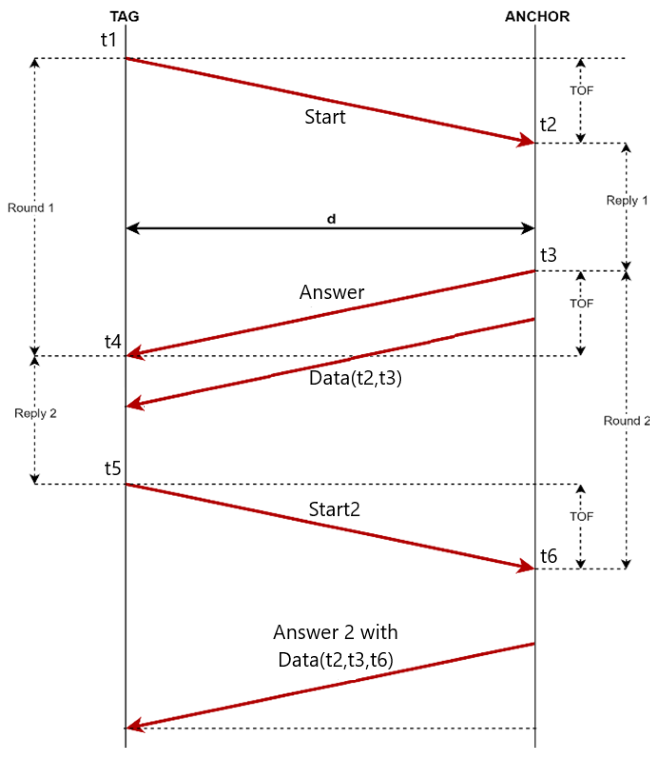
Two-way ranging (TWR). The two-way ranging method determines the time of flight of the RF signal and then it calculates the distance between the nodes by multiplying the time parameter by the speed of light. Figure 3 depicts the TWR method. The tag sends a start signal to the anchor at t1. The anchor receives this beacon at a timestamp t2, and then sends an answer at t3, which is received at t4 by the tag. The timestamps t2 and t3 are then sent to a tag in a data frame [80]. Finally, the tag computes the travelling time of the signal both ways and obtains a distance estimation d, which is given by:
d T W R = t 4 t 1 t 3 t 2 2 × c
where c denotes the speed of light (3 × 10⁸ m/s).
5.
Symmetrical double-sided two-way ranging (SDS-TWR). In symmetric double-sided two-way ranging, an additional cycle of sending and receiving signals is performed [80], leading to two additional timestamps, t5 and t6:
d S D S T W R = t 6 t 5 + t 4 t 1 ( t 3 t 2 ) 3 × c
where c denotes the speed of light (3 × 10⁸ m/s).
6.
Near-field electromagnetic range (NFER). The NFER method refers to any radio technology employing the near-field properties of radio waves.
7.
Received signal strength indication. RSSI is a term used to measure the relative quality of a received signal to a client device [76]. However, there is a direct proportion between the RSSI and the receiver–transmitter distance. This method matches the RSSI measurement to a receiver–transmitter distance. The formula for converting the RSSI measurement to distance is described below:
D = A ×〖(r/t)〗^B + C
where d is the distance in meters,
  • r is the RSSI measured by the device,
  • t is the RSSI measurement at 1 m,
  • and A, B, and C are constants.
RTLS implementations based on wireless signals (2D tracking) use the anchor and the tag hardware devices. A tag is a device that is attached to the moving object and communicates with all the static anchors to be localized. On the other hand, an anchor is a static device that is installed in a predefined location and receives signals from the tag devices. In the wireless signal tracking method, the tag’s location is calculated using an estimation of the relative distance from the static anchors, as presented in Figure 4.
When there are two predefined anchors (anchor 1 and anchor 2) and a tag is identified at distances r1 and r2 from the two anchors, there are exactly two points where the tag could be located (points A and B). This forces the use of a third anchor (anchor 3) to determine the exact location of the tag that is identified at a distance r3 from anchor 3 (Figure 4a). In ideal conditions, the intersection of the identified distances r from the anchors would be a single point (point A in the given example) but, in real-world conditions, every measurement includes an error; therefore an overall error in the final tag’s position is included in the calculations. The yellow region in Figure 4b illustrates the possible location of the tag due to measurement errors dr, shown as colored dotted circles. This example underscores the necessity of using at least three anchors to pinpoint a tag’s exact position in indoor environments and highlights how measurement inaccuracies affect the localization accuracy.
In the case of the visible tracking category, image recognition and visible light tracking algorithms (using lidar and infrared sensors) are used to process the camera frames and calculate the object’s position by matching the object on the image frame and then identify its exact position in the map.
Finally, the PDR category calculates the position of the object by using motion measurements and the previous known position of the object [22]. For example, if the acceleration on the three axis is measured using an accelerometer, we can easily calculate the velocity and then the new position of the moving object. The biggest shortfall of this method is the cumulative error when it calculates the new position of the tag (because each measurement is based on a previous position, which also contains a measurement error) and this could lead to inaccurate estimations. An external sensor (such as an RFID tag) could eliminate this error by passing through known locations that could instantly localize the object in the facility. However, this solution increases the complexity of the system and its power consumption, which is a significant problem for small devices, while it also increases the system’s cost.

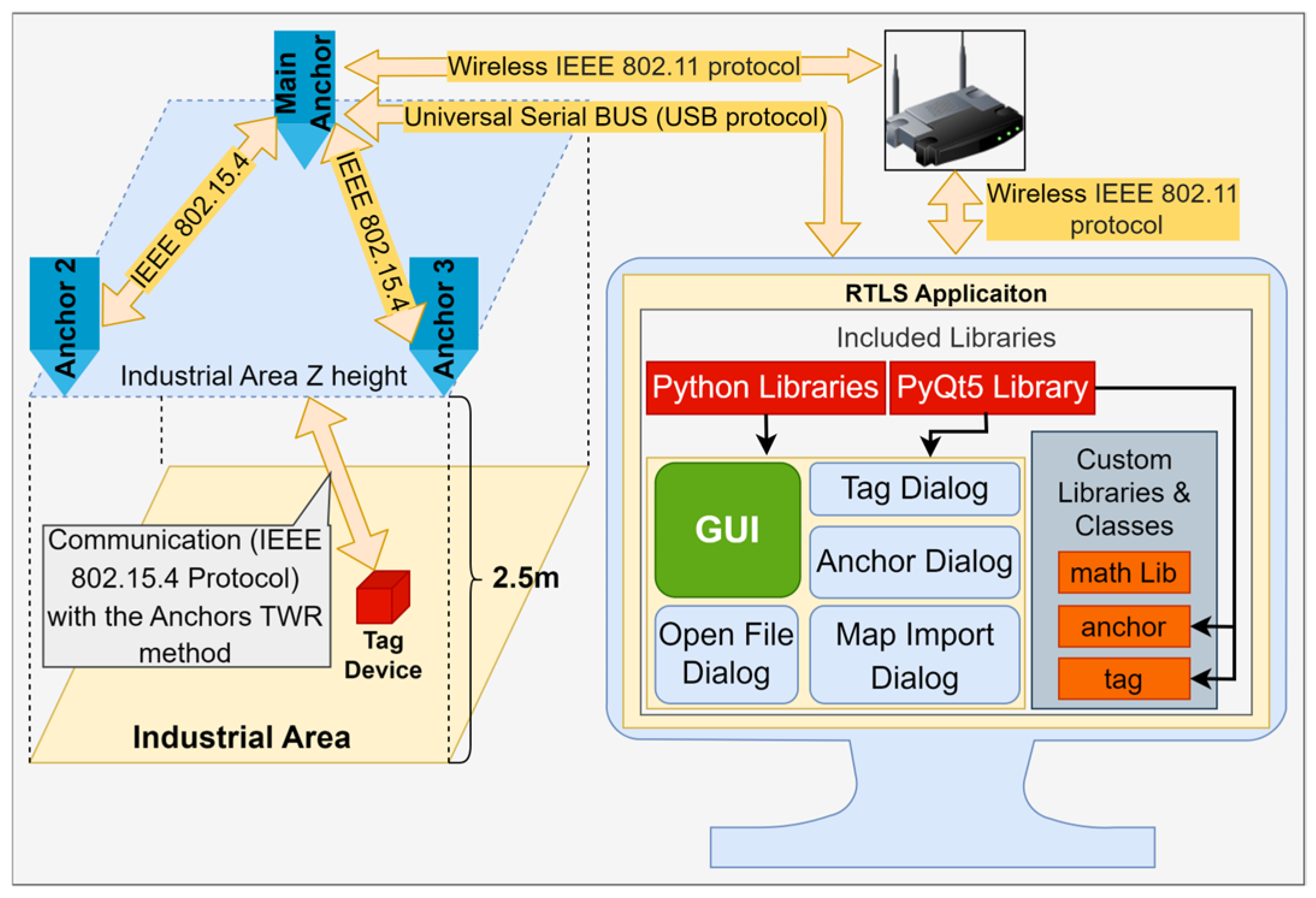
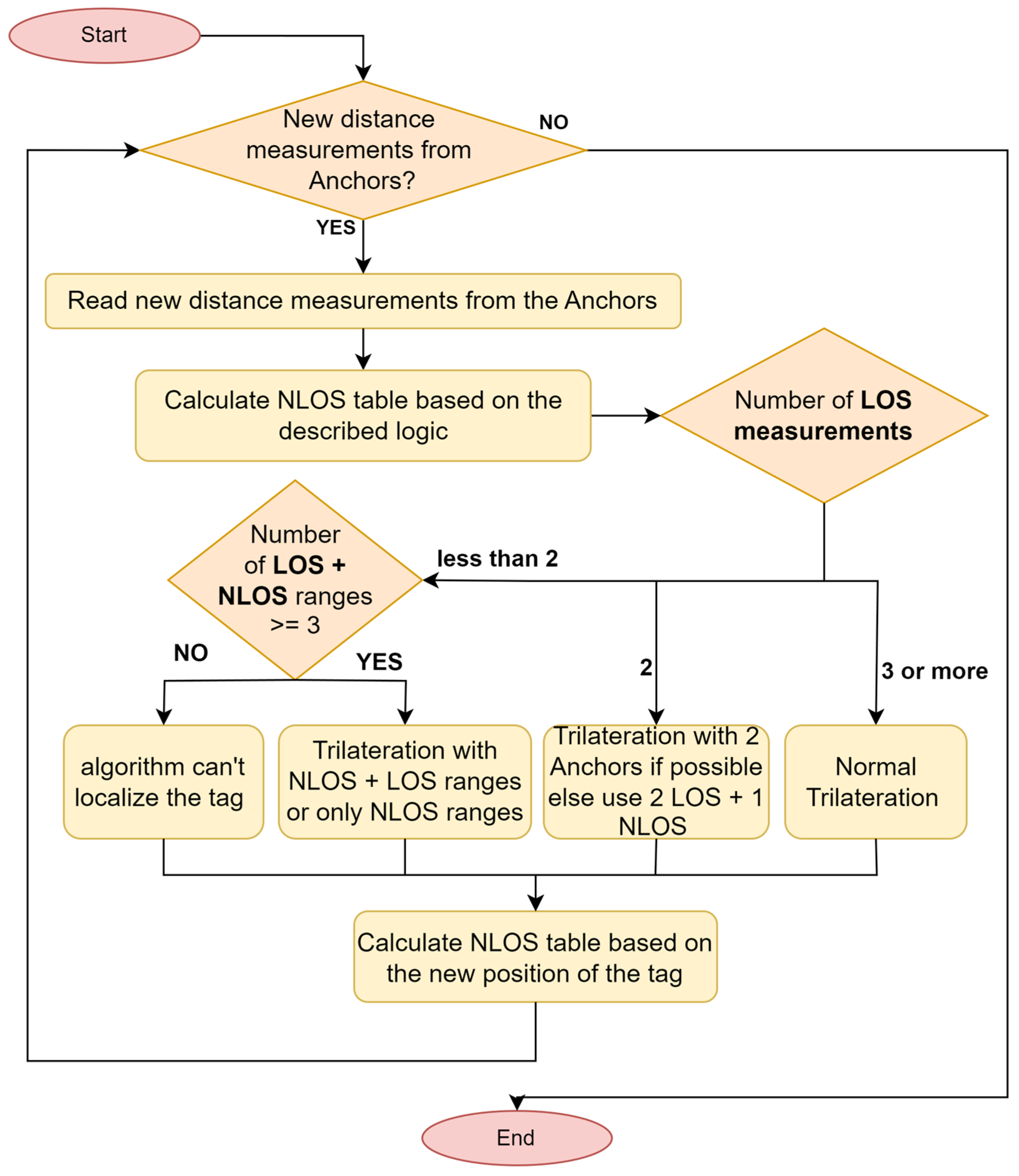
3.2. Proposed Real-Time Locating System

This section analyzes and describes the proposed RTLS, which is a combination of software and hardware. First, define the requirements of the system. Based on the analysis given in Section 2, the system must: (i) cover big areas; (ii) have high positioning accuracy; (iii) have low power consumption; (iv) maintain reasonable positioning accuracy in NLOS environments; (v) have a reasonable cost per square meter; and (vi) be scalable.
Based on the above analysis, we analyze the reasons that led us to select the UWB method from the above-described technologies for our RTLS. The most important requirement of the system was the cost per square meter of coverage area. The UWB method has low power consumption [81] and a high level of multipath resolution, it works well with a low signal-to-noise-ratio (SNR), and it has a high data rate of communication, which makes UWB a good solution for RTLSs [70,80]. In industries, we need to track assets that cover large distances, so an efficient way to track them with a reasonable cost emerges. The second requirement was the effective function in NLOS conditions (with metallic and non-metallic obstacles and structures between the anchors and tags) while maintaining the lowest error level. Additionally, in highly complex environments, the option to add more anchors should be available. A survey about RTLSs found that the UWB method is one of the most accurate and commonly implemented tracking methods for indoor environments when the area is covered by many structures and objects [71]. The average positioning error In LOS conditions for the MDEK1001 Development Kit (which uses DWM1000 modules) is 0.16 m, while 25% of the measurements had errors of less than 10 cm and the maximum measured position error was 0.89 m [75]. The UWB signals cover a large frequency band (3.1–10.6 GHz). For the abovementioned reasons, UWB technology was chosen; it is able to cover large areas and works better under disadvantageous conditions with an acceptable position error (some tens of centimeters) and with reasonable costs.
The proposed Implementation uses the DWM1000 UWB (Figure 5a) modules for anchor–tag communication and ranging calculations. These modules are wireless transceivers based on Qorvo’s DW1000 IC and they enable the real time tracking of objects. The Qorvo DW1000 chip is an IEEE 802.15.4 (2011)-compliant UWB transceiver that operates on six frequency bands with center frequencies between 3.5 and 6.5 GHz and a bandwidth of 500 or 900 MHz The advantages of these chips are: (i) the total range is high (300 m), which means that they can cover large areas (in indoor areas, the highest measured distance is 40 m, which is considered a high indoor range); (ii) the low power consumption (the tag device draws 99 mW for approximately 15 ms for each anchor–tag ranging measurement), which increases the device’s operational time; and (iii) the relevant high localization accuracy (10–20 cm based on the manufacturer’s specifications). The system uses four DWM1000 devices: one of them is the tag device and the other three are the anchor devices. The TWR technique is used to measure the anchor–tag ranges. The DWM1000 chip is tuned on Channel 5 with a 6.8 Mbps bit rate and a preamble length of 64 bits.
Several studies analyzed the accuracy of the DMW1000 modules by placing the anchors at different altitudes, and the optimized accuracy was recorded when the anchors were 2.2 m above the tag [69]. According to this experiment, the best altitude at which to place the anchor devices is approximately 2–2.5 m above the tag, and, assuming that tag devices are placed on assets 1 m from the ground, the best altitude for the anchors is 3–3.5 m above the ground. Theoretical studies of the signal properties were conducted, as well as an analysis of the geometrical limits of TDoA RTLS. They showed that the symmetrical positioning of the anchors significantly improves the overall accuracy of the system [74].
A beta version of a scalable and user-friendly software tool was also developed. Figure 6 illustrates the system architecture and the connections between the hardware and software components. The left side of Figure 6 shows an indoor environment where the tag and three anchors are installed. The tag device communicates with the anchors, exchanging data streams that include anchor–tag distance measurements using the IEEE 802.15 protocol. The tag first interacts with anchor 3 and anchor 2, and finally with anchor 1, which is designated as the main anchor. Once the range measurements are completed, the tag sends all three anchor–tag distance results to the main anchor. Then, the main anchor transmits the results to the PC where the software is installed. The software tool imports the map of the facility layout and dynamically plots the tag’s location on the 2D map to identify the asset’s movement. The Python programming language was used for the development of the software tool, as it is an established and scalable programming language. The PyQt5 python library was used for the Graphical User Interface and custom functions, and classes were developed to decode the anchor’s data and calculate the tag’s position. After the data stream’s transmission, the developed software is responsible for the data processing and finally for the position estimation. When the software receives data streams with the distance measurements, its first task is the measurement identification (LOS or NLOS) and then the calculation of the tag’s position. The NLOS identification of the proposed software tool is described below. When the software receives new anchor–tag measurements, it calculates the time difference between the last two measurements for each t a g i :
d t i = t 2 i t 1 i , i = 0 , , n T
d t i j = d t i , j = 0 , ,   n A , i = 0 , , n T  
where t 2 i is the latest timestamp for t a g i , t 1 i is the previous timestamp for t a g i , n A is the total number of anchor devices, and n T is the total number of the tag devices (when the system has more tags to track). The system receives all the distance measurements for a certain tag at the same time, and there is no need to calculate the dt for each anchor separately. In practice, the tag communicates with each anchor individually, with only a microsecond-level delay between transmissions, making the distance it moves during this short period negligible; thus, we can assume that the system receives them at the same time. Similarly, by subtracting two consecutive distance measurements, we determine the absolute value of the radial displacement between the t a g i and the a n c h o r j during the time window d t i j :
d r i j =   r i j , t 2 2 d Z a n c h o r j , t a g i 2   r i j , t 1 2 d Z a n c h o r j , t a g i 2 , f o r   i = 0 , , n T , j = 0 , ,   n A
where r i j , t 1 and r i j , t 2 denote the measured distances from a n c h o r j to t a g i at times t 1 and t 2 , respectively. d Z a n c h o r j , t a g i is the height difference between a n c h o r j and t a g i . Based on the maximum speed of the tag and the error of the equipment, the maximum distance variation for time window d t i j is:
d r i j , m a x = V m a x i × d t i j + σ e q u i p
where σ e q u i p is the theoretical localization error that the manufacturer provides for the equipment. Thus, to calculate the NLOS identification on every anchor–tag measurement, Equation (8) is used:
N L O S i j = 0 , d r i j     V m a x i × d t i j + σ e q u i p 1 , o t h e r w i s e  
where N L O S i j is a 2D table that describes whether the distance between t a g i and a n c h o r j is identified as LOS ( N L O S i j = 0) or NLOS ( N L O S i j = 1). If the absolute value of the radial displacement between the a n c h o r j and the t a g i exceeds the distance that the tag can cover at its maximum speed in the time window d t i j , the measurement becomes unreliable, suggesting that an obstruction is blocking the direct path communication between them; therefore, we can conclude that the communication was performed under NLOS conditions. Thus, before estimating the tag’s position, the algorithm compares all the anchor–tag distances with their previous measurements and characterizes them as LOS or NLOS. In the second step, we developed an algorithm that processes the received distance measurements for the estimation of the tag’s position. As the system captures data streams from the hardware components, the algorithm calculates the N L O S i j table for identifying the LOS/NLOS condition of each measurement. Based on data from each tag, the software calculates the tag’s position using the trilateration algorithm. In the event that there are measurements from more than three anchors, the extra anchors’ measurements are used for position verification purposes. If the tag’s position must be identified from two anchors, localization is still possible.
When only two anchors are available for the estimation of the tag’s location, Equation (9) is used:
x x 1 2 + y y 1 2 = d 1 2 x x 2 2 + y y 2 2 = d 2 2
The above system can either have a single solution, or two distinct x and y pairs, as shown in Figure 7. To solve the system, an extra source of information is needed, in order to pinpoint the tag’s location. In this case, the localization will be unfeasible if the tag moves further to one of the two half planes. If the distance between point A and B is two times greater than the distance that the tag can travel at the time window d t r i j we are sure that the tag is at the same half plane, and we can reject one of the two solutions.
Summarizing the above findings, the following inequality must be satisfied:
x A x B 2 + y A y B 2 > 2 × V m a x i × d t i j
Another solution involves including some limitations for the anchor devices. In most cases, the anchors are placed close to the walls, so one of the two solutions is unfeasible because it does not belong to the solution space (it is not in the industrial area). As a conclusion to the above analysis, the final algorithmic steps that calculate the tags’ location are presented; Figure 8 presents the flowchart of the algorithm.
Algorithm 1: System algorithm for NLOS minimization and tag position estimation
1: rij,t1, rij,t2, NLOSij ⟵ 0
2: while (1) do:
3:  rij,t1 ⟵ rij,t2
4:  read anchor’s data streams rij,t2 from USB/WiFi
5:  calculate new rij,t2, dtij and drij
6:  for i in Tags do:
7:   calculate newNLOSij for tag i based on Vmax speed
8:   numberOfLOSmeasurements = [];
9:   numberOfNLOSmeasurements = [];
10:   for j in Anchors do:
11:     if dr[i][j] > 0 and NLOS[i][j] = 0 and newNLOS[i][j] = 0 then
12:      numberOfLOSmeasurements.add(rij,t2);
13:     else
14:     numberOfNLOSmeasurements.add(rij,t2);
15:     end if
16:  end for
17:  if numberOfLOSmeasurements.size() > 3 then
18:    Tag i[x][y] ⟵ Normal_Trilateration(numberOfLOSmeasurements)
19:  else if numberOfLOSmeasurements.size() = 3 then
20:     Tag i[x][y] ⟵ Normal_Trilateration(numberOfLOSmeasurements)
21:  else if (numberOfLOSmeasurements.size() = 2 then
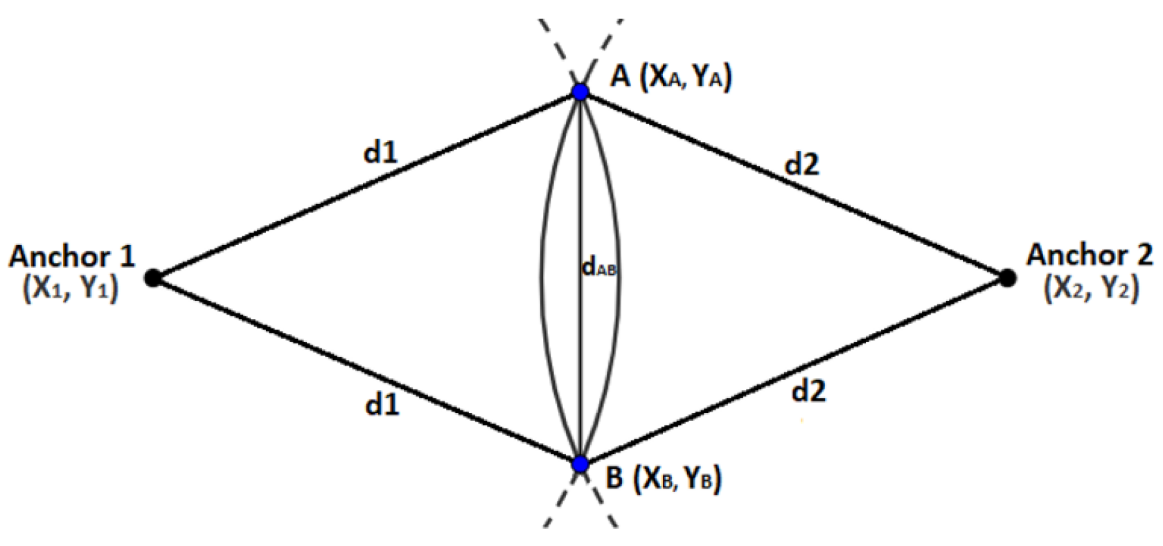
22:   pointA[x][y], pointB[x][y] ⟵ Find_2points_with_2_Anchors(Equation (9))
23:   if Equation (10) is satisfied then
24:    Tag i[x][y] ⟵ closest of pointA and pointB
25:   end if
26:  else if numberOfLOSmeasurements.size() + numberOfNLOSmeasurements.size() >= 3 then
27:      Tag i[x][y] ⟵ Normal_Trilateration(LOS + NLOS)
28:  else
29:      Error;//can’t calculate position for tag i
30:  end if
31:  if new position for tag i was calculated then
32:    NLOSij = newNLOSij
33:    if distance from anchor j verifies the new position, then
34:       NLOS[i][j] ⟵ 0;
35:    end if
36:  end for
37:  plotTagsToMap();
38: end while

4. Results and Discussion

In this section, a typical use case is described, using both the hardware devices and the developed software tool to dynamically monitor tags in an indoor environment. A computer that executes the proposed software tool is connected to the main anchor using the USB interface; it retrieves the relative anchor–tag distance measurements. The software calculates the exact location of the tags and plots them on the map (Figure 9). Thus, to determine the accuracy of the system (software and hardware), two experiments were conducted. In both experiments, the accuracy of the tag was measured in a 2D facility of approximately 26 square meters. Specifically, the experiments were executed by placing the tag at point A and then moving it consecutively to points B, C, D, E, and F (Figure 9a). In the first experiment, a normal trilateration algorithm was used without identifying NLOS conditions; in the second experiment, our proposed algorithm was used. In the normal trilateration algorithm, all three anchor–tag measurements are utilized, even when conducted under NLOS conditions, which can lead to increased ranging errors. The system’s accuracy and the deviation of the calculated points were measured to determine the overall localization error. For the experiment, the maximum movement speed V m a x i was 0.8 m/s. In Figure 9a, the actual points where the tag device was placed are shown with red dots. For each point, 100 samples (position estimations) were collected with a frequency of 1 samples/s, which leads to a constant d t i j of 1 s. It is worth noting that the experiments were conducted in an indoor area where a concrete pillar was used to obstruct the direct path between the tag and an anchor (with a different anchor each time). It is evident that the proposed environment cannot be a harsh NLOS environment; this plays a crucial role when the primary goal is the NLOS range correction. However, in our case, the concrete pillar in the facility obstructs the direct path between the anchor devices and the tag to demonstrate how the proposed algorithm reacts in such cases in order to provide a solution in NLOS conditions.
Significant localization errors are anticipated for points B, C and D, as the tag device communicates with the anchors under NLOS conditions (at point B, there is NLOS communication with anchor 3, at point C with anchor 2, and at point D with anchor 1). Even under NLOS conditions, the communication between the tag and the anchors was successful but this led to increased errors regarding the anchor–tag measured distances and provided an increased localization error. After the execution of the experiments, the deviations were plotted on a box plot graph to compare the results. In Figure 10, the box plots for 100 measurements at points B, C, and D are depicted; the overall NLOS errors (all 300 measurements from points B, C, and D) of the normal trilateration algorithm and the proposed algorithm are also illustrated.
The proposed algorithm in two of the three cases (on points B and D) was able to identify the NLOS conditions on the anchor–tag measurements and excluded the measurement that was identified as NLOS. For point C, the algorithm also recognized the NLOS communication between the tag and anchor 2. The problem in that case was that Equation (10) was not satisfied, producing the same results as the normal trilateration algorithm. In conclusion, the proposed algorithm helps with asset localization and has better accuracy when there are obstacles between the tag and the anchors as it can identify the existence of NLOS conditions. The algorithm can Identify and exclude error-prone measurements and track the tag more accurately. Finally, the RMSEs were calculated to highlight the accuracy of the system. Specifically, the RMSE was calculated for the two independent axis and for the Euclidean distance. For each point the x error is:
e r r o r x i = x R i x M i
where x R i is the actual tag’s position for the I measurement on the X axis and x M i is the relevant measured tag’s position. The R M S E X can be calculated as follows:
R M S E X = i = 1 n e r r o r x i 2 n
For each point, the RMSE was calculated based on the 100 estimated position measurements. It was observed that the position estimation varies more for points that face NLOS conditions while communicating with an anchor (Table 3). The error on the Y axis is similarly calculated by replacing the x variable with the y:
R M S E Y = i = 1 n ( y R i y M i ) 2 n
Finally, the R M S E X Y is calculated based on the Euclidean distance between the real-world and measured points and is described using the following equation:
R M S E X Y = i = 1 n ( x R i x M i ) 2 + ( y R i y M i ) 2 n
The RMSE values from the two experiments and for all the points under study are calculated and presented in Table 3.
Figure 11a shows the location error of the proposed algorithm at point B. The actual position of the tag is represented by the orange dot, while the blue points and the red “x” marks indicate the calculated positions using the normal trilateration method and the proposed algorithm, respectively. The maximum deviations for the proposed algorithm are 0.25 m on the X axis and 0.22 m on the Y axis. Additionally, we found that 80% of the observations had a Euclidean distance error of less than 0.18 m, whereas, with the normal trilateration algorithm, only 50% of the observations had this level of error. The maximum observed Euclidean errors for the normal trilateration and proposed algorithm were 0.26 m and 0.37 m, respectively. Thus, we can conclude that the RMSE of the measurements is at an acceptable level and very close to the hardware specifications. It is worth noting that one limitation of the proposed algorithm is its reliance on knowing the previous tag’s location, which necessitates either the initialization or initial localization of the tag using at least three anchors. However, it can be utilized in various positioning systems as a fallback solution when the NLOS range correction is ineffective.
Finally, a hypothesis test of the mean localization error between the two algorithms was conducted. The null hypothesis was that the mean difference of the localization error under NLOS conditions between the normal trilateration algorithm (M = 17.46 cm, SD = 55 cm, n = 200) and the proposed algorithm (M = 11.89, SD = 32 cm, n = 200) was lower than 4 cm. The results showed that the difference was significant, t(374) = 2.356, p = 0.009 (1 tail), and we can reject the null hypothesis. Thus, we can conclude that the proposed algorithm’s mean error is at least 4 cm lower than that of the normal trilateration algorithm.

5. Conclusions

The primary objective of driving our study was to develop an efficient RTLS solution tailored for industrial applications within the Industry 4.0 framework. This article presents a comparison of the state-of-the-art RTLS implementations, showing that UWB technology is in a mature state, while providing a taxonomy for the existing tracking technologies and a comparison matrix for supporting decision making in the selection of the most suitable technology for real-time tracking in indoor areas. Based on this analysis, the proposed RTLS solution (hardware and software) was developed. Additionally, we introduce an algorithm capable of determining a tag’s position using only two anchors under specific conditions. The results demonstrate that the proposed system effectively localizes assets with high accuracy, enabling industries to monitor their resources efficiently. As a result, the proposed method can achieve an RMSE of 0.18 m for 80% of the observations compared to 50% when using the normal trilateration method. The proposed method has a maximum error of 0.26 m, as compared to 0.37 m for the normal trilateration. The experiments showcased that the proposed algorithm improves the overall positioning error by 24%, reporting an RMSE of 0.124 m in comparison to the 0.163 m of the normal trilateration method. This provides a notable competitive edge, especially in industrial settings with numerous dynamic and static obstacles—such as corridors lined with tall racks—which frequently demand NLOS operations with limited anchors. Ultimately, the proposed system is suitable for tracking assets moving at low speeds, showing high accuracy in indoor environments (a positioning error of 10–20 cm), when provided with at least two LOS anchor–tag range measurements at any given position. The system has low power consumption, entailing low maintenance needs for portable devices. It also covers around 200 square meters using just three anchors, while allowing for the easy installation of additional anchors in areas with numerous obstacles (i.e., harsh NLOS environments).
The NLOS identification method that was used in this experiment, which relies on the maximum tag speed, has certain limitations. It requires the tag to move at low speeds to effectively determine when a new distance measurement is likely a false indication due to communication occurring under NLOS conditions. For future research, the algorithm could be further enhanced by incorporating more sophisticated and precise methods for NLOS identification that can be found in the literature [60,82]. This advancement would contribute to further improving the localization accuracy of the RTLS. Additionally, it is essential to conduct extensive testing of the proposed system in daily industrial operations to evaluate its performance under real-world conditions.

Author Contributions

Conceptualization, A.S.; methodology, A.S.; software, A.S.; validation, A.S.; investigation, A.S.; resources, A.S.; writing—original draft preparation, A.S.; writing—review and editing, D.B. and D.V.; visualization, A.S. and D.V.; supervision, D.B. and D.V. All authors have read and agreed to the published version of the manuscript.

Funding

This research received no external funding.

Institutional Review Board Statement

Not applicable.

Informed Consent Statement

Not applicable.

Data Availability Statement

The data presented in this study are available on request from the corresponding author due to privacy restrictions.

Conflicts of Interest

The authors declare no conflicts of interest.

Abbreviations

The following abbreviations are used in this manuscript:
AoAAngle of arrival
BLEBluetooth
FTMFine-time measurement
GAGenetic algorithm
GNSSGlobal navigation satellite system
IMUInertial measurement unit
IoTInternet of Things
IPSIndoor positioning system
LIDARLaser imaging detection and ranging
LOSLine-of-sight
NFERNear-field electromagnetic range
NLOSNon-line-of-sight
RFIDRadio frequency identification
RMSERoot mean square error
RSSIReceived signal strength identification
RTLSReal-time locating system
RTTRound-trip time
SDS-TWRSymmetrical double-sided two-way ranging
TDoATime difference of arrival
ToATime of arrival
ToFTime-of-flight
TWRTwo-way ranging
UAVUnmanned aerial vehicle
UWBUltra-wideband
VLCVisible light communication
VNVVariable noise variance Kalman filter

References

  1. Tao, F.; Zhang, H.; Liu, A.; Nee, A.Y.C. Digital Twin in Industry: State-of-the-Art. IEEE Trans. Ind. Inf. 2019, 15, 2405–2415. [Google Scholar] [CrossRef]
  2. Sisinni, E.; Saifullah, A.; Han, S.; Jennehag, U.; Gidlund, M. Industrial Internet of Things: Challenges, Opportunities, and Directions. IEEE Trans. Ind. Inf. 2018, 14, 4724–4734. [Google Scholar] [CrossRef]
  3. Boyes, H.; Hallaq, B.; Cunningham, J.; Watson, T. The Industrial Internet of Things (IIoT): An Analysis Framework. Comput. Ind. 2018, 101, 1–12. [Google Scholar] [CrossRef]
  4. Oesterreich, T.D.; Teuteberg, F. Understanding the Implications of Digitisation and Automation in the Context of Industry 4.0: A Triangulation Approach and Elements of a Research Agenda for the Construction Industry. Comput. Ind. 2016, 83, 121–139. [Google Scholar] [CrossRef]
  5. Hofmann, E.; Rüsch, M. Industry 4.0 and the Current Status as Well as Future Prospects on Logistics. Comput. Ind. 2017, 89, 23–34. [Google Scholar] [CrossRef]
  6. Zhao, Z.; Shen, L.; Yang, C.; Wu, W.; Zhang, M.; Huang, G.Q. IoT and Digital Twin Enabled Smart Tracking for Safety Management. Comput. Oper. Res. 2021, 128, 105183. [Google Scholar] [CrossRef]
  7. Kanan, R.; Elhassan, O.; Bensalem, R. An IoT-Based Autonomous System for Workers’ Safety in Construction Sites with Real-Time Alarming, Monitoring, and Positioning Strategies. Autom. Constr. 2018, 88, 73–86. [Google Scholar] [CrossRef]
  8. Ochoa-de-Eribe-Landaberea, A.; Zamora-Cadenas, L.; Velez, I. Untethered Ultra-Wideband-Based Real-Time Locating System for Road-Worker Safety. Sensors 2024, 24, 2391. [Google Scholar] [CrossRef]
  9. Shamsollahi, D.; Moselhi, O.; Khorasani, K. Data Integration Using Deep Learning and Real-Time Locating System (RTLS) for Automated Construction Progress Monitoring and Reporting. Autom. Constr. 2024, 168, 105778. [Google Scholar] [CrossRef]
  10. Thota, R.C.; Sara, S.M.; Sarwar Uddin, M.Y.; Bani-Yaghoub, M.; Sutkin, G. Accurate Estimation of Individual Transmission Rates Through Contact Analytics Using UWB Based Indoor Location Data. In Proceedings of the 2024 International Conference on Smart Applications, Communications and Networking, SmartNets 2024, Harrisonburg, VA, USA, 28–30 May 2024; Institute of Electrical and Electronics Engineers Inc.: New York, NY, USA, 2024. [Google Scholar]
  11. Sadowski, S.; Spachos, P. Comparison of RSSI-Based Indoor Localization for Smart Buildings with Internet of Things. In Proceedings of the 2018 IEEE 9th Annual Information Technology, Electronics and Mobile Communication Conference, IEMCON 2018, Vancouver, BC, Canada, 1–3 November 2018; Institute of Electrical and Electronics Engineers Inc.: New York, NY, USA, 2019; pp. 24–29. [Google Scholar]
  12. Chen, J.; Chen, H.; Luo, X. Collecting Building Occupancy Data of High Resolution Based on WiFi and BLE Network. Autom. Constr. 2019, 102, 183–194. [Google Scholar] [CrossRef]
  13. Zourmand, A.; Sheng, N.W.; Hing, A.L.K.; Rehman, M.A. Human Counting and Indoor Positioning System Using WiFi Technology. In Proceedings of the 2018 IEEE International Conference on Automatic Control and Intelligent Systems, I2CACIS 2018, Shah Alam, Malaysia, 20 October 2018; Institute of Electrical and Electronics Engineers Inc.: New York, NY, USA, 2019; pp. 142–147. [Google Scholar]
  14. Li, S.; Hedley, M.; Bengston, K.; Humphrey, D.; Johnson, M.; Ni, W. Passive Localization of Standard WiFi Devices. IEEE Syst. J. 2019, 13, 3929–3932. [Google Scholar] [CrossRef]
  15. Zhang, W.; Hua, X.; Yu, K.; Qiu, W.; Zhang, S.; He, X. A Novel WiFi Indoor Positioning Strategy Based on Weighted Squared Euclidean Distance and Local Principal Gradient Direction. Sens. Rev. 2019, 39, 99–106. [Google Scholar] [CrossRef]
  16. Luo, J.; Zhang, Z.; Wang, C.; Liu, C.; Xiao, D. Indoor Multifloor Localization Method Based on WiFi Fingerprints and LDA. IEEE Trans. Ind. Inf. 2019, 15, 5225–5234. [Google Scholar] [CrossRef]
  17. Hoang, M.T.; Yuen, B.; Dong, X.; Lu, T.; Westendorp, R.; Reddy, K. Recurrent Neural Networks for Accurate RSSI Indoor Localization. IEEE Internet Things J. 2019, 6, 10639–10651. [Google Scholar] [CrossRef]
  18. Ridolfi, M.; Vandermeeren, S.; Defraye, J.; Steendam, H.; Gerlo, J.; De Clercq, D.; Hoebeke, J.; Poorter, E. De Experimental Evaluation of Uwb Indoor Positioning for Sport Postures. Sensors 2018, 18, 168. [Google Scholar] [CrossRef] [PubMed]
  19. Kulmer, J.; Hinteregger, S.; Grosswindhager, B.; Rath, M.; Bakr, M.S.; Leitinger, E.; Witrisal, K. Using DecaWave UWB Transceivers for High-Accuracy Multipath-Assisted Indoor Positioning. In Proceedings of the 2017 IEEE International Conference on Communications Workshops, ICC Workshops 2017, Paris, France, 21–25 May 2017; pp. 1239–1245. [Google Scholar] [CrossRef]
  20. Witrisal, K.; Hinteregger, S.; Kulmer, J.; Leitinger, E.; Meissner, P. High-Accuracy Positioning for Indoor Applications: RFID, UWB, 5G, and Beyond. In Proceedings of the 2016 IEEE International Conference on RFID, RFID 2016, Orlando, FL, USA, 3–5 May 2016. [Google Scholar] [CrossRef]
  21. De Angelis, G.; Moschitta, A.; Carbone, P. Positioning Techniques in Indoor Environments Based on Stochastic Modeling of UWB Round-Trip-Time Measurements. IEEE Trans. Intell. Transp. Syst. 2016, 17, 2272–2281. [Google Scholar] [CrossRef]
  22. Guo, S.; Zhang, Y.; Gui, X.; Han, L. An Improved PDR/UWB Integrated System for Indoor Navigation Applications. IEEE Sens. J. 2020, 20, 8046–8061. [Google Scholar] [CrossRef]
  23. Yu, J.; Na, Z.; Liu, X.; Deng, Z. WiFi/PDR-Integrated Indoor Localization Using Unconstrained Smartphones. EURASIP J. Wirel. Commun. Netw. 2019, 2019, 41. [Google Scholar] [CrossRef]
  24. Kianfar, A.; Uth, F.; Baltes, R.; Clausen, E. Development of a Robust Ultra-Wideband Module for Underground Positioning and Collision Avoidance. Min. Metall. Explor. 2020, 37, 1821–1825. [Google Scholar] [CrossRef]
  25. Bharadwaj, R.; Swaisaenyakorn, S.; Parini, C.G.; Batchelor, J.C.; Alomainy, A. Impulse Radio Ultra-Wideband Communications for Localization and Tracking of Human Body and Limbs Movement for Healthcare Applications. IEEE Trans. Antennas Propag. 2017, 65, 7298–7309. [Google Scholar] [CrossRef]
  26. Woods, J.M.; Adcock, S.J.J. Validation of an Indoor Real-Time Location System for Tracking Sheep. Comput. Electron. Agric. 2024, 227, 109535. [Google Scholar] [CrossRef]
  27. Bendavid, Y.; Rostampour, S.; Berrabah, Y.; Bagheri, N.; Safkhani, M. The Rise of Passive RFID RTLS Solutions in Industry 5.0. Sensors 2024, 24, 1711. [Google Scholar] [CrossRef] [PubMed]
  28. Gharat, V.; Colin, E.; Baudoin, G.; Richard, D. Indoor Performance Analysis of LF-RFID Based Positioning System: Comparison with UHF-RFID and UWB. In Proceedings of the 2017 International Conference on Indoor Positioning and Indoor Navigation, IPIN 2017, Sapporo, Japan, 18–21 September 2017; pp. 1–8. [Google Scholar] [CrossRef]
  29. Diallo, A.; Lu, Z.; Zhao, X. Wireless Indoor Localization Using Passive RFID Tags. Procedia Comput. Sci. 2019, 155, 210–217. [Google Scholar] [CrossRef]
  30. Qi, J.; Liu, G.P. A Robust High-Accuracy Ultrasound Indoor Positioning System Based on a Wireless Sensor Network. Sensors 2017, 17, 2554. [Google Scholar] [CrossRef] [PubMed]
  31. Chen, H.; Guan, W.; Li, S.; Wu, Y. Indoor High Precision Three-Dimensional Positioning System Based on Visible Light Communication Using Modified Genetic Algorithm. Opt. Commun. 2018, 413, 103–120. [Google Scholar] [CrossRef]
  32. Yadav, R.; Chugh, H.; Jain, V.; Baneriee, P. Indoor Navigation System Using Visual Positioning System with Augmented Reality. In Proceedings of the 2018 International Conference on Automation and Computational Engineering, ICACE 2018, Greater Noida, India, 3–4 October 2018; pp. 52–56. [Google Scholar] [CrossRef]
  33. Rodríguez-Araújo, J.; Rodríguez-Andina, J.J.; Fariña, J.; Chow, M.Y. Field-Programmable System-on-Chip for Localization of UGVs in an Indoor Ispace. IEEE Trans. Ind. Inf. 2014, 10, 1033–1043. [Google Scholar] [CrossRef]
  34. Duong, S.N.; Trinh, A.V.T.; Dinh, T.M. Bluetooth Low Energy Based Indoor Positioning on IOS Platform. In Proceedings of the 2018 IEEE 12th International Symposium on Embedded Multicore/Many-Core Systems-on-Chip, MCSoC 2018, Hanoi, Vietnam, 12–14 September 2018; pp. 57–63. [Google Scholar] [CrossRef]
  35. Pau, G.; Arena, F.; Gebremariam, Y.E.; You, I. Bluetooth5.1: An Analysis of Direction Finding Capability for High-Precision Location Services. Sensors 2021, 21, 3589. [Google Scholar] [CrossRef]
  36. Astafiev, A.V.; Zhiznyakov, A.L.; Privezentsev, D.G. Development of Indoor Positioning Algorithm Based on Bluetooth Low Energy Beacons for Building RTLS-Systems. In Proceedings of the 2019 International Russian Automation Conference, RusAutoCon 2019, Sochi, Russia, 8–14 September 2019; pp. 1–5. [Google Scholar] [CrossRef]
  37. Jeon, J.S.; Kong, Y.; Nam, Y.; Yim, K. An Indoor Positioning System Using Bluetooth RSSI with an Accelerometer and a Barometer on a Smartphone. In Proceedings of the 2015 10th International Conference on Broadband and Wireless Computing, Communication and Applications, BWCCA 2015, Krakow, Poland, 4–6 November 2015; pp. 528–531. [Google Scholar] [CrossRef]
  38. Woo, S.; Jeong, S.; Mok, E.; Xia, L.; Choi, C.; Pyeon, M.; Heo, J. Application of WiFi-Based Indoor Positioning System for Labor Tracking at Construction Sites: A Case Study in Guangzhou MTR. Autom. Constr. 2011, 20, 3–13. [Google Scholar] [CrossRef]
  39. Abbas, M.; Elhamshary, M.; Rizk, H.; Torki, M.; Youssef, M. WiDeep: WiFi-Based Accurate and Robust Indoor Localization System Using Deep Learning. In Proceedings of the 2019 IEEE International Conference on Pervasive Computing and Communications, PerCom 2019, Kyoto, Japan, 11–15 March 2019. [Google Scholar] [CrossRef]
  40. Karlsson, F.; Karlsson, M.; Bernhardsson, B.; Tufvesson, F.; Persson, M. Sensor Fused Indoor Positioning Using Dual Band WiFi Signal Measurements. In Proceedings of the 2015 European Control Conference, ECC 2015, Linz, Austria, 15–17 July 2015; pp. 1669–1672. [Google Scholar] [CrossRef]
  41. Haryanto, D.K.; Karyono, K.; Hutagalung, S. The Comparison between Geo-Magnetism and WiFi for Indoor Positioning System for Public Places. In Proceedings of the 2018 International Conference on Robotics, Biomimetics, and Intelligent Computational Systems, Robionetics 2018, Bandung, Indonesia, 8–10 August 2018; pp. 1–5. [Google Scholar] [CrossRef]
  42. Hernández, N.; Parra, I.; Corrales, H.; Izquierdo, R.; Ballardini, A.L.; Salinas, C.; García, I. WiFiNet: WiFi-Based Indoor Localisation Using CNNs. Expert. Syst. Appl. 2021, 177, 114906. [Google Scholar] [CrossRef]
  43. Park, K.M.; Lee, B.H.; Lee, E.; Kim, S.C.; Choi, J. GPS-Aided Automatic Site Survey Method for WiFi RTT-Based Positioning. IEEE Trans. Veh. Technol. 2023, 72, 13120–13129. [Google Scholar] [CrossRef]
  44. Orfanos, M.; Perakis, H.; Gikas, V.; Retscher, G.; Mpimis, T.; Spyropoulou, I.; Papathanasopoulou, V. Testing and Evaluation of Wi-Fi RTT Ranging Technology for Personal Mobility Applications. Sensors 2023, 23, 2829. [Google Scholar] [CrossRef] [PubMed]
  45. Rana, L.; Park, J.G. An Enhanced Indoor Positioning Method Based on RTT and RSS Measurements under LOS/NLOS Environment. IEEE Sens. J. 2024, 24, 31417–31430. [Google Scholar] [CrossRef]
  46. Horn, B.K.P. Round-Trip Time Ranging to Wi-Fi Access Points Beats GNSS Localization. Appl. Sci. 2024, 14, 7805. [Google Scholar] [CrossRef]
  47. Krummenauer, A.; Gomes, V.E.d.O.; Nardelli, V.C. Estimation of Measurement Uncertainty of the Real-Time Location System (RTLS) with Ultra-Wideband (UWB) Technology. Metrology 2023, 3, 113–130. [Google Scholar] [CrossRef]
  48. Qorvo DW1000. Available online: https://www.qorvo.com/products/p/DW1000 (accessed on 16 January 2025).
  49. Ubisense. Available online: https://ubisense.com (accessed on 17 January 2025).
  50. SEWIO. Available online: https://www.sewio.net (accessed on 16 January 2025).
  51. Jiménez, A.R.; Seco, F. Comparing Decawave and Bespoon UWB Location Systems: Indoor/Outdoor Performance Analysis. In Proceedings of the 2016 International Conference on Indoor Positioning and Indoor Navigation, IPIN 2016, Alcala de Henares, Spain, 4–7 October 2016. [Google Scholar] [CrossRef]
  52. Ruiz, A.R.J.; Granja, F.S. Comparing Ubisense, BeSpoon, and DecaWave UWB Location Systems: Indoor Performance Analysis. IEEE Trans. Instrum. Meas. 2017, 66, 2106–2117. [Google Scholar] [CrossRef]
  53. Schroeer, G. A Real-Time UWB Multi-Channel Indoor Positioning System for Industrial Scenarios. In Proceedings of the IPIN 2018—9th International Conference on Indoor Positioning and Indoor Navigation, Nantes, France, 24–27 September 2018; pp. 3–7. [Google Scholar] [CrossRef]
  54. OptiTrack. Available online: https://www.optitrack.com (accessed on 16 January 2025).
  55. Ambrose, A.; Savur, C.; Sahin, F. Low Cost Real Time Location Tracking with Ultra-Wideband. In Proceedings of the 2022 17th Annual System of Systems Engineering Conference, SOSE 2022, Rochester, NY, USA, 7–11 June 2022; Institute of Electrical and Electronics Engineers Inc.: New York, NY, USA, 2022; pp. 445–450. [Google Scholar]
  56. Bing, W.; Yanyan, L.; Qingquan, L.; Yan, Z. A High-Precision Dynamic Indoor Localization Algorithm Based on UWB Technology. In Proceedings of the 5th IEEE Conference on Ubiquitous Positioning, Indoor Navigation and Location-Based Services, UPINLBS 2018, Wuhan, China, 22–23 March 2018; pp. 1–7. [Google Scholar] [CrossRef]
  57. Ochoa-De-eribe-landaberea, A.; Zamora-Cadenas, L.; Peñagaricano-Muñoa, O.; Velez, I. UWB and IMU-Based UAV’s Assistance System for Autonomous Landing on a Platform. Sensors 2022, 22, 2347. [Google Scholar] [CrossRef]
  58. Al-Khaddour, M.; Ali, M.; Yousef, M. Line-of-Sight Aware Accurate Collaborative Localization Based on Joint TDoA and AoA Measurements in UWB-MIMO Environment. Clust. Comput. 2024, 27, 7637–7655. [Google Scholar] [CrossRef]
  59. Plangger, J.; Govindasamy Ravichandran, H.; Rodin, S.C.; Atia, M. System Design and Performance Analysis of Indoor Real-Time Localization Using UWB Infrastructure. In Proceedings of the SysCon 2023—17th Annual IEEE International Systems Conference, Proceedings, Vancouver, BC, Canada, 17–20 April 2023; Institute of Electrical and Electronics Engineers Inc.: New York, NY, USA, 2023. [Google Scholar]
  60. Zhao, Y.; Wang, M. The LOS/NLOS Classification Method Based on Deep Learning for the UWB Localization System in Coal Mines. Appl. Sci. 2022, 12, 6484. [Google Scholar] [CrossRef]
  61. Kim, D.H.; Pyun, J.Y. Enhanced UWB Ranging Utilizing Denoising Neural Network. IEEE Commun. Lett. 2024, 28, 1029–1033. [Google Scholar] [CrossRef]
  62. Kim, J.H.; An, H.G.; Komuro, N.; Kim, W.S. Bias and Deviation Map-Based Weighted Graph Search for NLOS Indoor RTLS Calibration. Electronics 2024, 13, 3993. [Google Scholar] [CrossRef]
  63. Yao, L.; Wu, Y.W.A.; Yao, L.; Liao, Z.Z. An Integrated IMU and UWB Sensor Based Indoor Positioning System. In Proceedings of the 2017 International Conference on Indoor Positioning and Indoor Navigation, IPIN 2017, Sapporo, Japan, 18–21 September 2017; pp. 1–8. [Google Scholar] [CrossRef]
  64. De Cock, C.; Joseph, W.; Martens, L.; Trogh, J.; Plets, D. Multi-Floor Indoor Pedestrian Dead Reckoning with a Backtracking Particle Filter and Viterbi-Based Floor Number Detection. Sensors 2021, 21, 4565. [Google Scholar] [CrossRef] [PubMed]
  65. Hyun, J.; Oh, T.; Lim, H.; Myung, H. UWB-Based Indoor Localization Using Ray-Tracing Algorithm. In Proceedings of the 2019 16th International Conference on Ubiquitous Robots, UR 2019, Jeju, Republic of Korea, 24–27 June 2019; pp. 98–101. [Google Scholar] [CrossRef]
  66. Vandermeeren, S.; Steendam, H. PDR/UWB Based Positioning of a Shopping Cart. IEEE Sens. J. 2021, 21, 10864–10878. [Google Scholar] [CrossRef]
  67. Vleugels, R.; Van Herbruggen, B.; Fontaine, J.; De Poorter, E. Ultra-Wideband Indoor Positioning and Imu-Based Activity Recognition for Ice Hockey Analytics. Sensors 2021, 21, 4650. [Google Scholar] [CrossRef]
  68. Pérez-Solano, J.J.; Ezpeleta, S.; Claver, J.M. Indoor Localization Using Time Difference of Arrival with UWB Signals and Unsynchronized Devices. Ad Hoc Netw. 2020, 99, 102067. [Google Scholar] [CrossRef]
  69. Athikulwongse, K.; Suwatthikul, C.; Chantaweesomboon, W. Impact of Altitude of Anchors on Performance of UWB Real-Time Locating System. In Proceedings of the 2018 International Conference on Embedded Systems and Intelligent Technology and International Conference on Information and Communication Technology for Embedded Systems, ICESIT-ICICTES 2018, Khon Kaen, Thailand, 7–9 May 2018; pp. 1–6. [Google Scholar] [CrossRef]
  70. Alarifi, A.; Al-Salman, A.; Alsaleh, M.; Alnafessah, A.; Al-Hadhrami, S.; Al-Ammar, M.A.; Al-Khalifa, H.S. Ultra Wideband Indoor Positioning Technologies: Analysis and Recent Advances. Sensors 2016, 16, 707. [Google Scholar] [CrossRef] [PubMed]
  71. Kunhoth, J.; Karkar, A.G.; Al-Maadeed, S.; Al-Ali, A. Indoor Positioning and Wayfinding Systems: A Survey. Hum. Centric Comput. Inf. Sci. 2020, 10, 18. [Google Scholar] [CrossRef]
  72. Yassin, A.; Nasser, Y.; Awad, M.; Al-Dubai, A.; Liu, R.; Yuen, C.; Raulefs, R.; Aboutanios, E. Recent Advances in Indoor Localization: A Survey on Theoretical Approaches and Applications. IEEE Commun. Surv. Tutor. 2017, 19, 1327–1346. [Google Scholar] [CrossRef]
  73. Yoon, P.K.; Zihajehzadeh, S.; Kang, B.S.; Park, E.J. Robust Biomechanical Model-Based 3-D Indoor Localization and Tracking Method Using UWB and IMU. IEEE Sens. J. 2017, 17, 1084–1096. [Google Scholar] [CrossRef]
  74. Grasso, P.; Innocente, M.S. Theoretical Study of Signal and Geometrical Properties of Two-Dimensional UWB-Based Indoor Positioning Systems Using TDoA. In Proceedings of the 2020 6th International Conference on Mechatronics and Robotics Engineering, ICMRE 2020, Barcelona, Spain, 12–15 February 2020; pp. 130–134. [Google Scholar] [CrossRef]
  75. Simedroni, R.; Puschita, E.; Palade, T.; Dolea, P.; Codau, C.; Buta, R.; Pastrav, A. Indoor Positioning Using Decawave MDEK1001. In Proceedings of the 2020 International Workshop on Antenna Technology, iWAT 2020, Bucharest, Romania, 25–28 February 2020. [Google Scholar] [CrossRef]
  76. Martínez del Horno, M.; Orozco-Barbosa, L.; García-Varea, I. A Smartphone-Based Multimodal Indoor Tracking System. Inf. Fusion 2021, 76, 36–45. [Google Scholar] [CrossRef]
  77. Truong-Quang, V.; Ho-Sy, T. Maximum Convergence Algorithm for WiFi Based Indoor Positioning System. Int. J. Electr. Comput. Eng. 2021, 11, 4027–4036. [Google Scholar] [CrossRef]
  78. Chen, W. Personnel Precise Positioning System of Coal Mine Underground Based on UWB. J. Phys. Conf. Ser. 2021, 1920, 012115. [Google Scholar] [CrossRef]
  79. Šinko, S.; Marinič, E.; Poljanec, B.; Obrecht, M.; Gajšek, B. Performance-Oriented UWB RTLS Decision-Making Approach. Sustainability 2022, 14, 11456. [Google Scholar] [CrossRef]
  80. Pestourie, B.; Beroulle, V.; Fourty, N. Security Evaluation with an Indoor UWB Open Platform: Acknowledgment Attack Case Study. In Proceedings of the IEEE 30th Annual International Symposium on Personal, Indoor and Mobile Radio Communications (PIMRC): Track 3: Mobile and Wireless Networks, Istanbul, Turkey, 8–11 September 2019; IEEE: New York, NY, USA, 2019. ISBN 9781538681107. [Google Scholar]
  81. Mayer, P.; Magno, M.; Schnetzler, C.; Benini, L. EmbedUWB: Low Power Embedded High-Precision and Low Latency UWB Localization. In Proceedings of the 2019 IEEE 5th World Forum on Internet of Things (WF-IoT), Limerick, Ireland, 15–18 April 2019; Institute of Electrical and Electronics Engineers: New York, NY, USA, 2019; p. 814, ISBN 9781538649800. [Google Scholar]
  82. Silva, B.; Hancke, G.P. IR-UWB-Based Non-Line-of-Sight Identification in Harsh Environments: Principles and Challenges. IEEE Trans. Ind. Inf. 2016, 12, 1188–1195. [Google Scholar] [CrossRef]
Figure 1. Research methodology.
Applsci 15 02689 g001
Figure 2. Article categorization based on tracking technology after 2017.
Applsci 15 02689 g002
Figure 3. Two-way ranging and symmetrical double-sided two-way ranging methods.
Applsci 15 02689 g003
Figure 4. Trilateration technique: (a) in ideal conditions; (b) in real-world conditions where each anchor–tag distance includes a measurement error.
Applsci 15 02689 g004
Figure 5. (a) Qorvo DWM1000 module; (b) Esp32 development board; (c) the developed anchor–tag board; (d) the 3D printed enclosure.
Applsci 15 02689 g005
Figure 6. System and application architecture.
Applsci 15 02689 g006
Figure 7. Trilateration with two LOS anchor–tag measurements.
Applsci 15 02689 g007
Figure 8. Flowchart of the proposed algorithm.
Applsci 15 02689 g008
Figure 9. (a) The developed RTLS application and the positions where the tag device was placed; (b) experimental environment.
Applsci 15 02689 g009
Figure 10. Box plot of the Euclidean error at the NLOS points for (i) the normal trilateration algorithm and (ii) the proposed algorithm.
Applsci 15 02689 g010
Figure 11. (a) Actual tag position at point B and estimated positions with the normal trilateration and the proposed algorithm. (b) Cumulative distribution function of the Euclidean error of the normal trilateration and the proposed algorithm.
Applsci 15 02689 g011
Table 1. Comparison of tracking technologies.
RTLS TechnologiesAccuracyLOS/NLOS ImpactRangeComplexityCost
RFIDMid-LowLowMid
UltrasoundHigh-LowLowMid
Visible LightHigh-MidHighHigh
IMUMidLowHighHighLow
BluetoothLowHighMidLowLow
Image RecognitionHigh-MidHighHigh
Wi-Fi 2.4 GHz RSSILowHighHighLowLow
Wi-Fi 5 GHz RSSILowHighHighLowLow
Wi-Fi FTM RTTMidMidHighLowLow
Ultra-Wide BandMidLowHighLowMid
Table 3. Comparison of the positioning errors of the normal trilateration and proposed algorithm.
Point (X,Y)Normal Trilateration Algorithm ErrorProposed RLTS System Error
X RMSEY RMSEEuclidean RMSEX RMSEY RMSEEuclidean RMSE
A (4.40,3.00) (100 samples)0.0710.0680.0980.0600.0740.095
B (2.50,3.20) (100 samples)0.1430.1410.2010.0970.1100.147
C (2.40,3.80) (100 samples)0.1470.1360.2010.1180.1260.173
D (1.25,3.90) (100 samples)0.1310.1580.2050.0850.0790.115
E (1.00,3.00) (100 samples)0.0850.1120.1400.0700.0660.096
F (1.60,2.00) (100 samples)0.0600.0640.0880.0680.0690.097
Overall error (600 samples)0.1120.1180.1630.0860.0900.124
Disclaimer/Publisher’s Note: The statements, opinions and data contained in all publications are solely those of the individual author(s) and contributor(s) and not of MDPI and/or the editor(s). MDPI and/or the editor(s) disclaim responsibility for any injury to people or property resulting from any ideas, methods, instructions or products referred to in the content.

