Article

Study of Reasonable Roof Cutting Parameters of Dense-Drilling Roof Cutting and Pressure Relief Self-Forming Roadway in Non-Pillar Mining

1
School of Energy and Mining Engineering, Xi’an University of Science and Technology, Xi’an 710054, China
2
Key Laboratory of Western Mines and Hazard Prevention, Ministry of Education of China, Xi’an 710054, China
3
Shaanxi Ruineng Coal Industry Co., Ltd. Yan’an 716000, China
*
Author to whom correspondence should be addressed.
Appl. Sci. 2025, 15(5), 2685; https://doi.org/10.3390/app15052685
Submission received: 8 February 2025 / Revised: 15 February 2025 / Accepted: 28 February 2025 / Published: 3 March 2025

Abstract

:
Roof cutting by dense drilling is one of the main methods of gob-side entry retaining. Taking the 203 working face of the Ruineng Coal Mine as the engineering background, a mechanical model is established to clarify the roof breaking mechanism. Numerical simulation is conducted to analyze the roof cutting effects of different parameters, and reasonable roof cutting parameters are identified. The results show that: ① The increase in roof cutting height is beneficial to roof cutting, but excessive height will cause stress concentration of the ‘key structure’ on the side of the coal pillar. ② It is difficult to cut off the roof when the roof cutting angle is too small, and the cantilever length of the roof increases when the roof cutting angle is too large. ③ The larger the borehole spacing, the smaller the plastic penetration rate between boreholes. The optimal parameters of roof cutting are determined as follows: roof cutting height 8 m; roof cutting angle 15°; aperture size 48 mm; hole spacing at 200 mm. The deformation of the resulting roadway is controllable, indicating that the key parameter determination method is effective.

1. Introduction

The technology of gob-side entry retaining enables mining without the coal pillar by eliminating the section coal pillar. Traditional gob-side entry retaining technology is primarily in the form of roadside filling support, which requires the support body to have ‘high strength, compressibility and tightness’ to control roof subsidence and gob sealing. However, the process of constructing the roadside filling support body is complex, costly and time-consuming [1,2]. Roof cutting and pressure relief gob-side entry retaining is based on the theory of roof cutting by ‘short-arm beam’ [3], which eliminates the roadside filling support body and forms the roadway side with the help of the broken and expansive filling gob of rock. Compared with traditional roadside filling support gob-side entry retaining technology, this process is simple, the speed of roadway formation is fast, the cost performance is high, and the adaptability to different geological conditions is strong. It has been widely used in China [4,5,6].
Current roof cutting technology is primarily based on directional cumulative blasting and hydraulic fracturing. The directional cumulative blasting is simple to operate and has a large controllable range, but it has a certain impact on the safety of the stope space and is difficult to apply in high gas mines [7,8]. Hydraulic fracturing softens the rock mass through a large number of high-pressure hydraulic fractures, which offers higher safety than shaped blasting but has higher requirements for the water stability of the roadway’s surrounding rock [9,10,11]. In recent years, some mines have adopted an advanced arrangement of roof dense drilling and roof cutting to relieve pressure. This method has the advantages of low cost, easy operation, strong applicability and small disturbance to the surrounding rock of the roadway [12,13,14]
Dense drilling technology is often used to relieve the pressure of surrounding rock in high ground-stress roadways. Many scholars have extensively studied this approach. Findings reveal that the essence of the pressure relief technology of borehole surrounding rock is to artificially weaken the local structural integrity of the roadway and transfer the stress concentration of its surrounding rock [15,16]. The stress release caused by crack propagation and penetration between boreholes is the fundamental reason for the pressure relief effect of boreholes [17]. Increasing the aperture or reducing the spacing between boreholes will increase the degree of crack propagation and thus increase the effects of pressure relief [18]. After the excavation of dense drilling, the width ratio of the pressure relief zone can be increased by using a larger aperture and smaller spacing, and the weakening effects of dense drilling on the rock mass can be improved. Field tests prove that the discontinuous, weak surface induced by dense drilling can effectively improve the stress environment of roadways [19]. According to the deformation control effect of different pressure relief drilling parameters on high-stress roadways, the degree of pressure relief is divided into insufficient pressure relief, sufficient pressure relief and excessive pressure relief. A range of drilling parameters under sufficient pressure relief can be obtained [20]. In recent years, dense drilling technology has also been used in the process of roof cutting and pressure relief gob-side entry retaining. The use of dense drilling to weaken the roof will be subject to tensile stress concentration when the roof is bent and deformed, so that the borehole weakening zone is vulnerable to tensile failure. Dense drilling can absorb the expansion deformation of the immediate roof, reduce the deformation of some roadways and achieve the effect of roof cutting and pressure relief [21,22]. Although dense drilling and roof cutting can achieve gob-side entry retaining, and the deformation of the retained roadway can meet the normal use requirements, compared with pre-splitting blasting roof cutting, there is the problem of large deformation and long deformation time of the roadway [23,24]. Based on the mine example of intensive borehole roof cutting gob-side entry retaining technology, the key parameters of intensive borehole roof cutting and pressure relief gob-side entry retaining are determined by the engineering analogy method. The gob-side entry retaining test carried out in the return airway of the 11,210 working face of the Zhaojiazhai Mine demonstrated its good effectiveness [25,26].
However, there is a lack of theoretical research on the technology of gob-side entry retaining with roof cutting and pressure relief by dense drilling, and there are relatively few studies on the selection of key parameters of boreholes. Therefore, this paper takes the Ruineng Coal Mine as the research background, discusses the mechanism of dense-drilling roof cutting through theoretical research, and preliminarily determines the key parameters of dense-drilling roof cutting and pressure relief. On this basis, the numerical simulation method is used to optimize the drilling parameters and determine the optimal dense-drilling roof cutting scheme. The monitoring results and the final roadway forming effect verify the effectiveness and practicability of the key parameters determination method of roof cutting, which provides a theoretical basis for the field engineering application of dense-drilling roof cutting and pressure relief gob-side entry retaining technology.

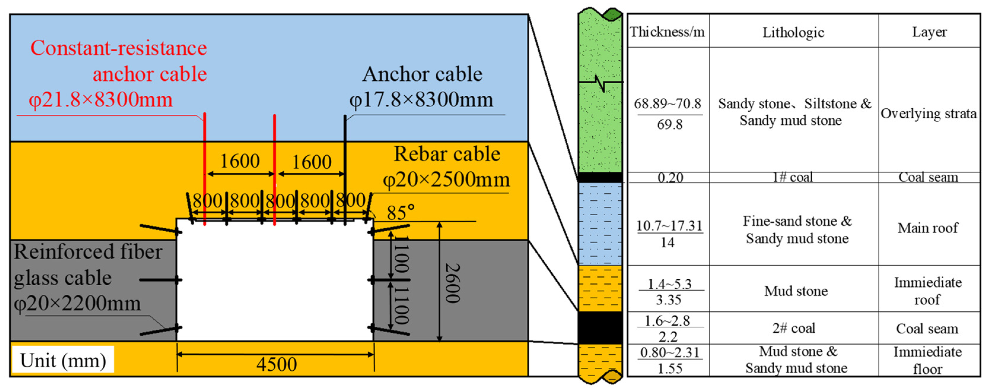
2. Engineering Background

The main mining 2# coal seam in the Ruineng Coal Mine is nearly horizontal, and the thickness of the coal seam is between 1.6 and 2.8 m, with an average of 2.2 m. The length of the 203 working face is 150 m, and the 203 transportation roadway is used as the gob-side roadway. Seven borehole peeping points were arranged and named 1 #~7 #. The peep results show that the lithology of the immediate roof of the working face is mainly black mudstone. The lithology of the basic roof is mainly gray-white fine-grained sandstone; the direct bottom is mudstone and sandy mudstone, containing a small amount of aluminum mudstone. The roof strata are relatively complete as a whole, and the rock mass strength in the local area is low and the water stability is poor. The layout of the working face and the peeping results of the surrounding rock structure are shown in Figure 1. Field sampling and determination of the physical and mechanical parameters of coal rock are shown in Table 1.
The section of the 203 transportation roadway is rectangular, and the length × width of the roadway section is 4.5 m × 2.6 m. The coupling support roof of ‘ordinary anchor cable + constant-resistance and large-deformation anchor cable’ is adopted. Compared with the ordinary anchor cable, the constant-resistance anchor cable has the characteristics of high strength, high constant resistance and high pre-tightening force. By improving the bending moment of the roof rock layer, the bearing capacity of the deep rock mass itself can be brought into full play [27]. The pillar diagram of the roadway support section and the roof and floor lithology are shown in Figure 2.

3. Determination of Key Parameters

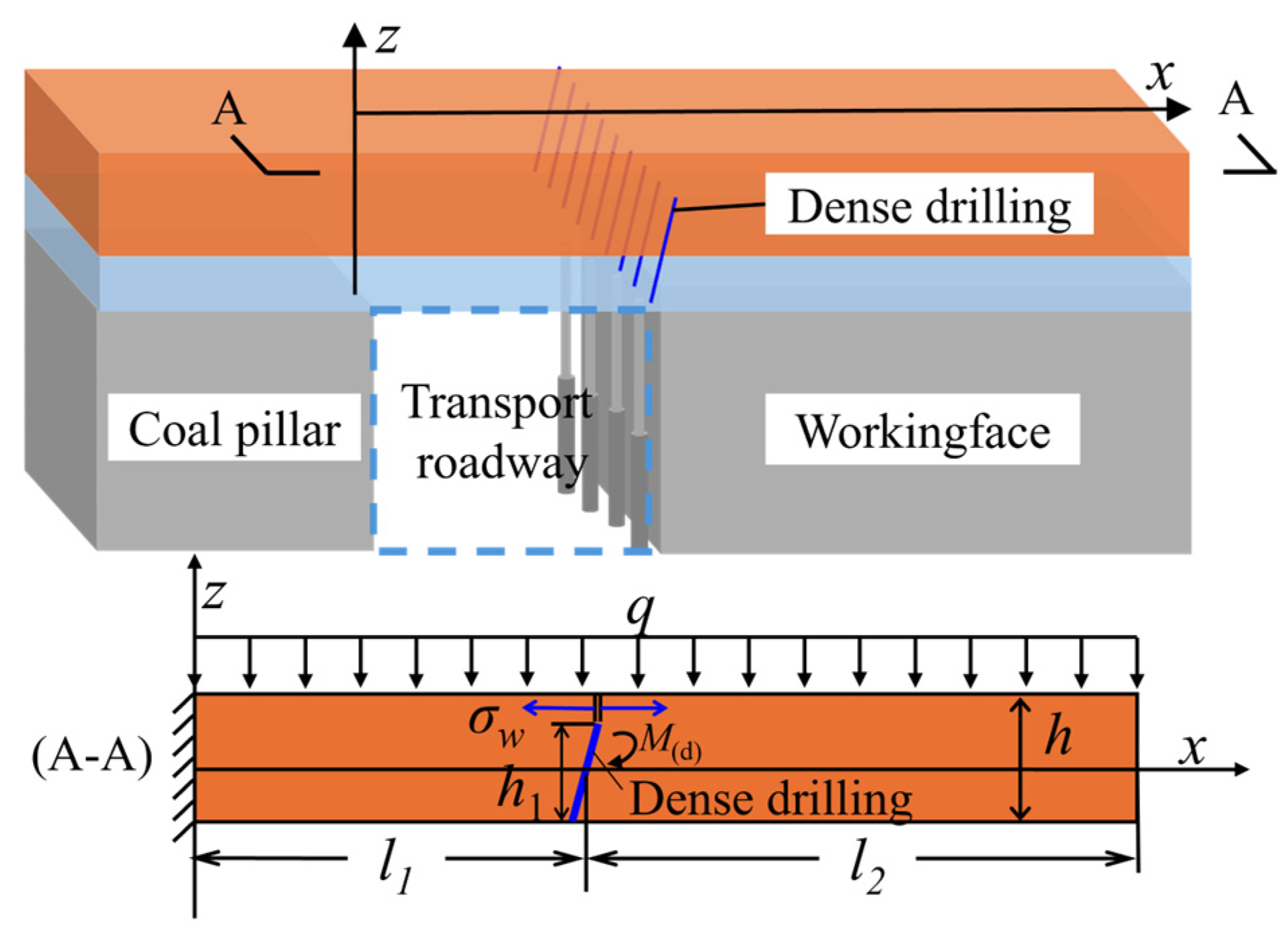
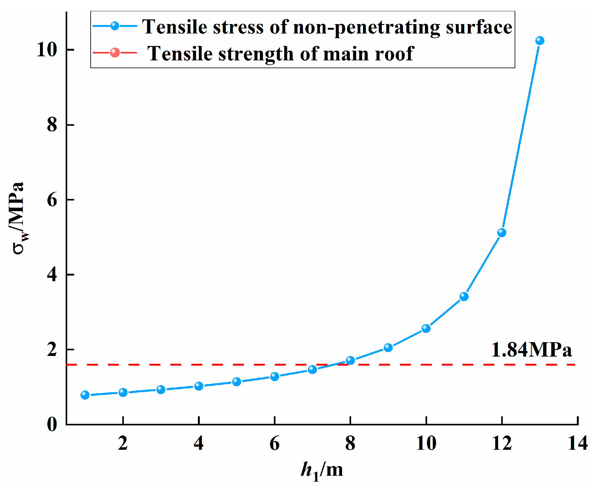
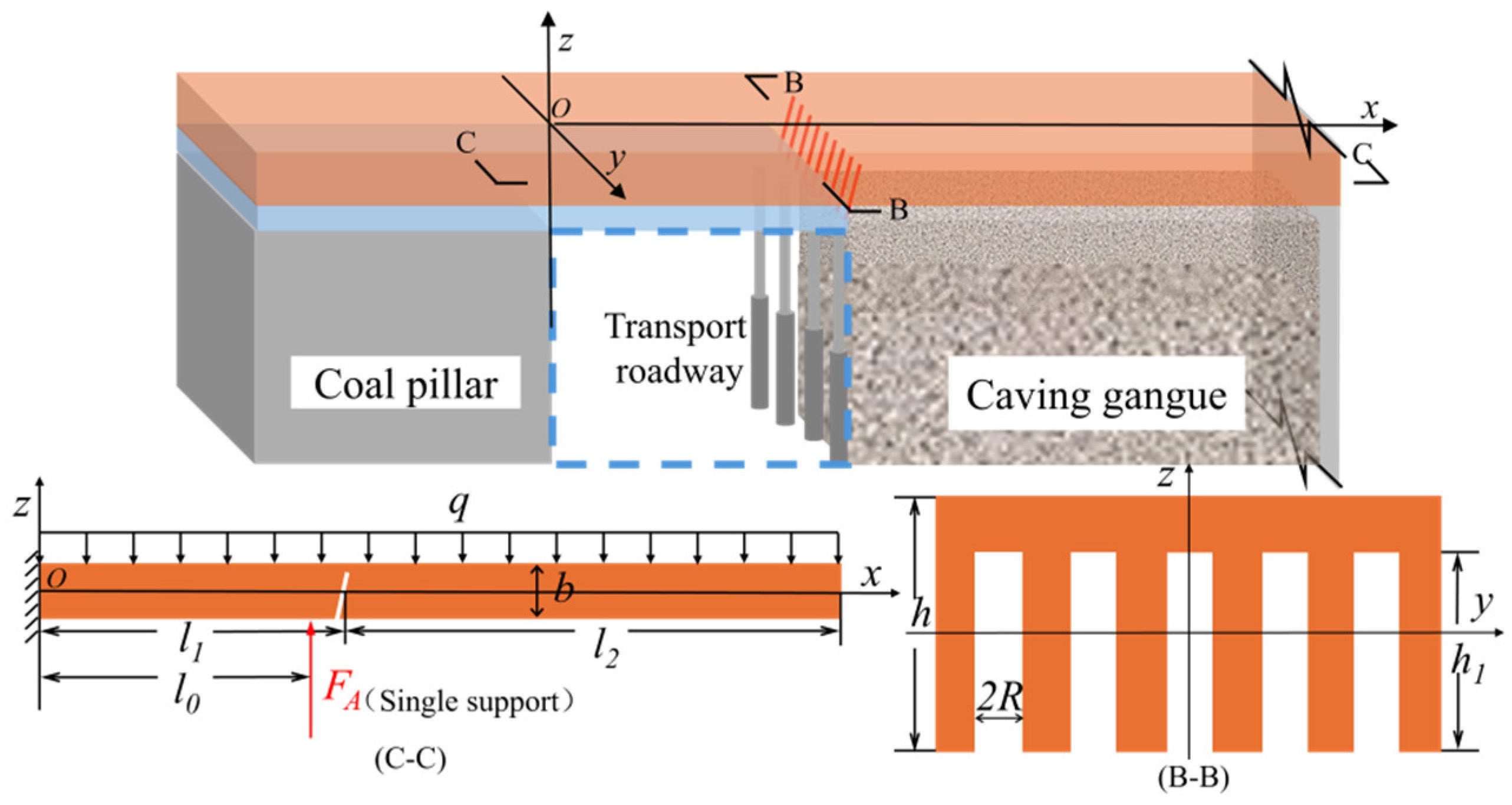
3.1. The Control Mechanism of Roof Cutting Height on Roof Breaking

The cutting height of the roof is determined by the expansion coefficient of the broken rock block and the mining height of the coal seam. Therefore, the cutting height H of the caving gangue in the goaf to fill the goaf and finally form a stable state of compaction is:
H = M K P 1
In Equation (1): KP is the expansion coefficient of rock, taking 1.3; M is the mining height of the coal seam (m), taking 2.2 m. According to Equation (1), the roof cutting height required for the roof broken gangue to fill the goaf should not be less than 7.3 m.
When the thickness of the main roof strata is small, the dense drilling can completely penetrate the main roof to break and sink. At this time, the roof cutting height can be determined as the sum of the thickness of the immediate roof and the main roof. However, when the thickness of the basic roof strata is large, it is difficult to achieve dense drilling through the basic roof strata completely. At this time, only part of the basic roof strata can be considered to be cut off, so that the part of the roof pre-splitting cutting seam that is not penetrated can be smoothly broken in the process of roof rotation and sinking in the gob. The mechanical model of the main roof strata when partial roof cutting is established is shown in Figure 3.
σ w = M ( d ) W t
M ( d ) = 1 2 q l 2 2
W t = 1 12 b ( h h 1 ) 2
In the formula: σw is the tensile stress on the non-penetrated surface of the basic roof rock; M(d) is the bending moment on the cutting top surface when the cantilever beam rotates and sinks; l1 is the width of the roadway; l2 is the lateral cantilever length of the main roof; h is the thickness of the main roof; h1 is the height of dense drilling.
By substituting (3) and (4) into (2), the relationship between σw and h1 is obtained as shown in Figure 4:
From Figure 4, it can be seen that the greater the height of the roof cutting seam of the intensive drilling hole h1, the greater the tensile stress σw acting on the non-penetrating surface of the roof cutting. When σw is greater than the tensile strength of the rock mass, the roof is broken. For instance, when h1 = 7.8 m, σw = 1.86 MPa, which is greater than the tensile strength of the rock mass, so that when the roof cutting height > 7.8 m, the roof can be broken and the broken gangue can be filled with the goaf.

3.2. The Control Mechanism of Roof Cutting Angle on Roof Breaking

A reasonable pre-splitting roof cutting angle can reduce the friction between the roof of the gob and the roof of the gob-side entry, so that the roof of the gob is easy to separate along the pre-splitting cutting surface and cut off smoothly.
With the advance of the working face, the roof rock breaks after reaching the limit span. The stability of the formed masonry beam structure is mainly controlled by the key rock block B. The force of the hinge point of rock block A and rock block B is shown in Figure 5. The horizontal thrust formed by rock block B on the pre-splitting slit section is T, and the shear force on the slit section is Q.
According to the ‘S-R’ stability theory of masonry beam structure, the relationship and equilibrium conditions between the forces of rock blocks are as follows:
( T cos θ Q sin θ ) tan φ Q cos θ + T sin θ
Q T tan ( φ θ )
In order to ensure that the key rock block B of the main roof slides smoothly along the pre-splitting cutting surface after roof cutting, the structural instability conditions can be obtained according to the above formula:
θ φ arctan Q T
Substitute into T = q l 2 2 2 ( h Δ ) , Q = q l 2 can be obtained:
θ φ arctan 2 ( h Δ ) l 2
In the formula: θ is the roof cutting angle (°); φ is the internal friction angle of the rock (°); h is the thickness of the rock mass (m); Δ is the subsidence of the rock mass (m); l2 is the lateral span (m) of rock block B.
Among them, the rotary subsidence Δ of rock block B is the gap between the immediate roof collapse and the basic roof. The collapse thickness of the immediate roof rock layer is Σh, and the height of the rock layer collapse and accumulation is KPΣh. The calculation formula of Δ is obtained:
Δ = M h ( K P 1 )
In the formula: M is the mining height of the coal seam (m); KP is the bulking coefficient of the rock.
Taking M = 2.2 m, KP = 1.3 into the Equation (9), the rotary subsidence of rock block B is Δ = 1.15 m.
The lateral span l2 of rock block B can be determined according to the cantilever breaking length of the basic roof rock block:
l 2 = h R T 3 q
In the formula, h is the thickness of the rock block (m); RT is the ultimate tensile strength (MPa) of the base roof; q is the load per unit area of the main roof rock mass (MPa).
Take h = 14 m, RT = 3.78 MPa, q = 0.5 MPa. Substituting into Equation (10), the lateral span l2 of rock block B is 22.2 m.
Substituting the rotary subsidence Δ of rock block B, the lateral span l2 of rock block B and the internal friction angle φ = 42° into Equation (8), θ ≥ 11.9° is obtained.

3.3. Control Mechanism of Aperture on Roof Breaking

Increasing the aperture can increase the radius of the pressure relief zone, which is conducive to the formation of a weakening zone in the coal body. Reducing the hole spacing results in fuller crack propagation around the hole [28,29]. Based on the theory of material mechanics, the mechanical model of the roof cantilever beam under the influence of dense drilling is constructed for stress analysis.
According to the mechanical model shown in Figure 6, the bending moment equation M2(x) and the shear force equation F2s(x) of the cantilever beam are:
M 2 x = q b l 1 + l 2 x 2 2                                                       l 0 x l 1 + l 2 q b l 1 + l 2 x 2 2 F A l 0 x           0 x l 0
F 2 S x = q b l 1 + l 2 x                                                       l 0 x l 1 + l 2 q b l 1 + l 2 x F A                                   0 x l 0
In the formula: b is the thickness of the beam (m); l1 is the roadway width (m); l0 is the width of the gob-side roadway (m); l2 is the lateral cantilever length of the roof (m).
According to the theory of material mechanics, the corresponding normal stress and shear stress can be expressed as:
σ x , z = M x I y z
τ x , z = F S x S y * I y b *
In the formula, Iy is the moment of inertia of the beam (m4); S*y is the static moment of the beam (m3); b* is the width (m) at the neutral axis of the beam.
From the bending moment equation and shear force equation of the cantilever beam shown in Equations (11) and (12), it can be seen that the bending moment and shear force at the O section of the fixed end are the largest. According to the normal stress and shear stress equations shown in Equations (15) and (16), when the roof is not cut by dense drilling, the normal stress and shear stress at the O section of the fixed end are also the largest, and the roof is destroyed first.
Therefore, in order to ensure the success of roof cutting, the maximum normal stress and maximum shear stress on the B section should be greater than the maximum normal stress and maximum shear stress on the O section:
σ B max σ O max > 1 ,   τ B max τ O max > 1
At the same time, it is ensured that the maximum normal stress and maximum shear stress are greater than the strength limit of the rock beam, that is:
σ B max > σ c ,   σ B max > σ c
After roof cutting, the moment of inertia IBy and static moment S B y * of the roof borehole can be expressed as
I B y = A z 2 d A = b h 3 12 R h 1 3 12 + 2 R h 1 h h 1 2 2
S B y * = b h 2 z h 4 + z 2                                                                           h 1 h 2 z h 2 1 8 b 2 R h 2 2 R h 1 2 h h 1 1 2 b z 2                       0 z h 1 h 2 b 2 R h 2 4 z 2                                                                           h 2 z 0
In the formula: h is the thickness of the roof (m); h1 is the drilling depth (m); R is the diameter of the drilling (m).
From Equations (17) and (18), when R = 0 (i.e., no dense drilling), the moment of inertia Iy and the static moment S y * on the cross section can be simplified as:
I y = b h 3 12
S y * = 1 8 b h 2 1 2 b z 2
From Equations (19) and (20), the bending moment MO2 and shear force FSO2 on the O section can be expressed as:
M O 2 = q b l 1 + l 2 2 2 F A l 0
F S O 2 = q b l 1 + l 2 F A
By substituting Equations (19) to (22) into Equations (13) and (14), the normal stress σO2(z) and shear stress τO2(z) on the O section can be expressed as follows:
σ O 2 z = M O 2 I y z = 12 z b h 3 q b l 1 + l 2 2 2 F A l 0
τ O 2 z = F S O 2 S y * I y b = 6 b h 3 h 2 4 z 2 q b l 1 + l 2 F A
According to Equations (23) and (24), the maximum normal stress and maximum shear stress on the O section can be expressed as follows:
σ O 2 max = M O 2 I y h 2 = 6 b h 2 q b l 1 + l 2 2 2 F A l 0
τ O 2 max = F S O 2 S y max * I y b = 3 2 1 b h q b l 1 + l 2 F A
Similarly, the bending moment MB2 and shear force FSB2 on the B-section can be expressed as:
M B 2 = q b l 2 2 2
F S B 2 = q b l 2
The conditions for the success of the roof cutting in Equations (25) to (28) are as follows:
σ B 2 max σ O 2 max = b b 8 R h 1 h 3 + 12 R h 1 h 2 6 R h 1 h q b l 2 2 2 q b l 1 + l 2 2 2 F A l 0 > 1
τ B 2 max τ O 2 max = b b 2 R 16 R h 1 h 2 + 16 R h 1 h b 8 R h 1 h 3 + 12 R h 1 h 2 6 R h 1 h b 2 R q b l 2 q b l 1 + l 2 F A > 1
Simplified:
σ B 2 max = 6 h b h 3 8 R h 1 3 6 R h 2 h 1 + 12 R h h 1 2 q b l 2 2 2 > σ c
τ B 2 max = 3 2 b 2 R h 2 16 R h 1 2 + 16 R h h 1 b h 3 8 R h 1 3 6 R h 2 h 1 + 12 R h h 1 2 b 2 R q b l 2 > τ c
According to Formulas (31) and (32), the normal stress and shear stress on section B are positively correlated with the aperture R. The roof cutting height H > 7.8 m, b = 14 m, q = 0.5 MPa, l2 = 22.2 m obtained is substituted into Formulas (31) and (32), and the pore size R should be greater than 20 mm.

3.4. The Influence Mechanism of Hole Spacing on the Plastic Zone of Round Hole

After determining the aperture, it is necessary to select the appropriate borehole spacing. The surrounding rock near the roof cutting borehole will be damaged by plastic deformation due to mining. The radius R0 of the plastic zone around the circular hole can be calculated by Equation (33). The minimum distance of the plastic zone interaction between adjacent boreholes is the hole spacing D = 2R0.
R 0 = R p 0 + C 0 cot ϕ 1 sin ϕ C 0 cot ϕ 1 sin ϕ 2 sin ϕ
where R is the aperture (mm); p0 is hydrostatic pressure (MPa); C0 is the cohesion of rock (MPa); and ϕ is the internal friction angle (°).
According to the People’s Republic of China Coal Industry Standard MT/T 984-2006 [30], the main sizes of the drill bit with a diameter greater than 40 mm are 48 mm, 55 mm, 65 mm, 75 mm and 94 mm in the coal or semi-coal rock strata with a uniaxial compressive strength of less than 50 MPa. Substituting into Equation (33), the relationship between D and the radius of plastic zone R0 and the diameter of borehole 2R is shown in Table 2.
Considering the ease of the construction of the roadway space, a roof cutting hole diameter of 48 mm is selected, and the hole spacing is limited to no more than 166 mm.

4. Numerical Simulation of Roof Cutting Parameters

Combined with theoretical analysis, the numerical simulation method is used to analyze the effect of roof cutting and pressure relief roadway retaining with different parameters, and the optimal scheme is selected. The 3DEC_DP 5.20 software, which can accurately characterize the actual situation of opening, swelling and scattering after the failure of the roadway’s surrounding rock, is selected for simulation.

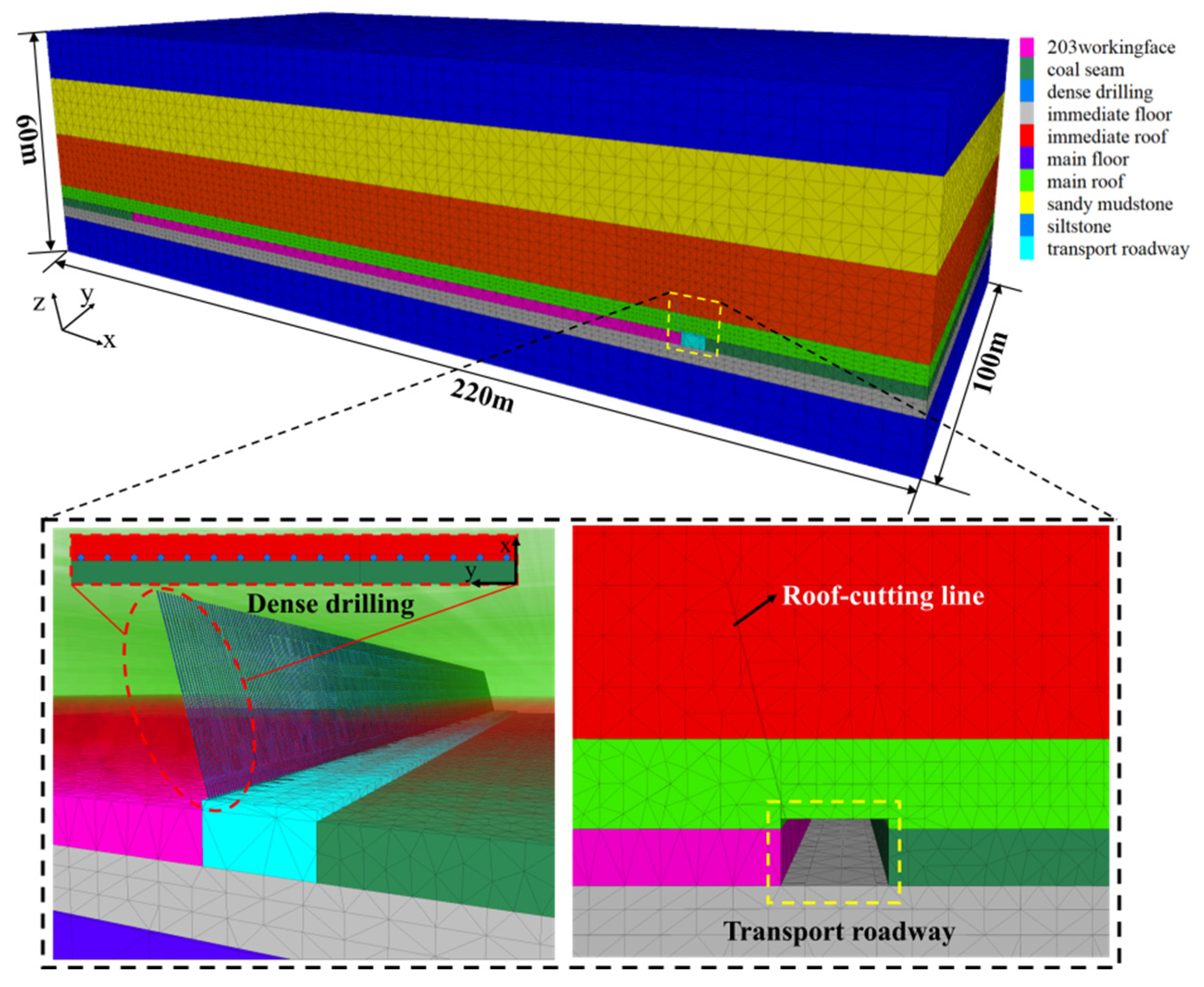
4.1. Establishment of Numerical Model

The Mohr–Coulomb model is selected as the constitutive model, and the model size is length × width × height = 220 m × 100 m × 60 m. The width × height of the roadway is 4.5 m × 2.6 m, and the pre-set roof cutting seam is densely drilled in the roof near the working face. The numerical calculation model is shown in Figure 7.
The mechanical parameters of each layer of the model are shown in Table 1 and the mechanical parameters of the joint are shown in Table 3. Horizontal and vertical displacement constraints are applied around the numerical model and along its lower boundary, and an equivalent vertical uniform load is applied on the upper boundary according to the buried depth. Since dense drilling is arranged in advance and the pressure relief zone is formed around the borehole to weaken the strength of the roof, the internal Fish function is used to re-parameterize the mechanical properties of the roof strata, so that the mechanical parameters of the strata decrease with the increase of the plastic shear strain, and then the dynamic process of the strength weakening of the rock mass is simulated [31].

4.2. Numerical Simulation Experiment Scheme

The geomechanical parameters and the section size of the roadway are set as constants. The model working face is excavated along the Y-axis direction, and the advancing distance is 10 m, to a total of 100 m. Three numerical simulation schemes of I, II and III are designed, and the single control variable method is adopted. The variable of scheme I is the cutting height, the variable of scheme II is the different cutting angles, and the variable of scheme III is different drilling spacing. In the process of model establishment, the joints of dense drilling are divided according to the experimental scheme. After the initial balance of the model, the numerical experiment is carried out in the order of roadway excavation, dense drilling excavation, working face mining. The specific numerical simulation scheme is shown in Table 4.

4.3. Numerical Simulation of Cutting Height

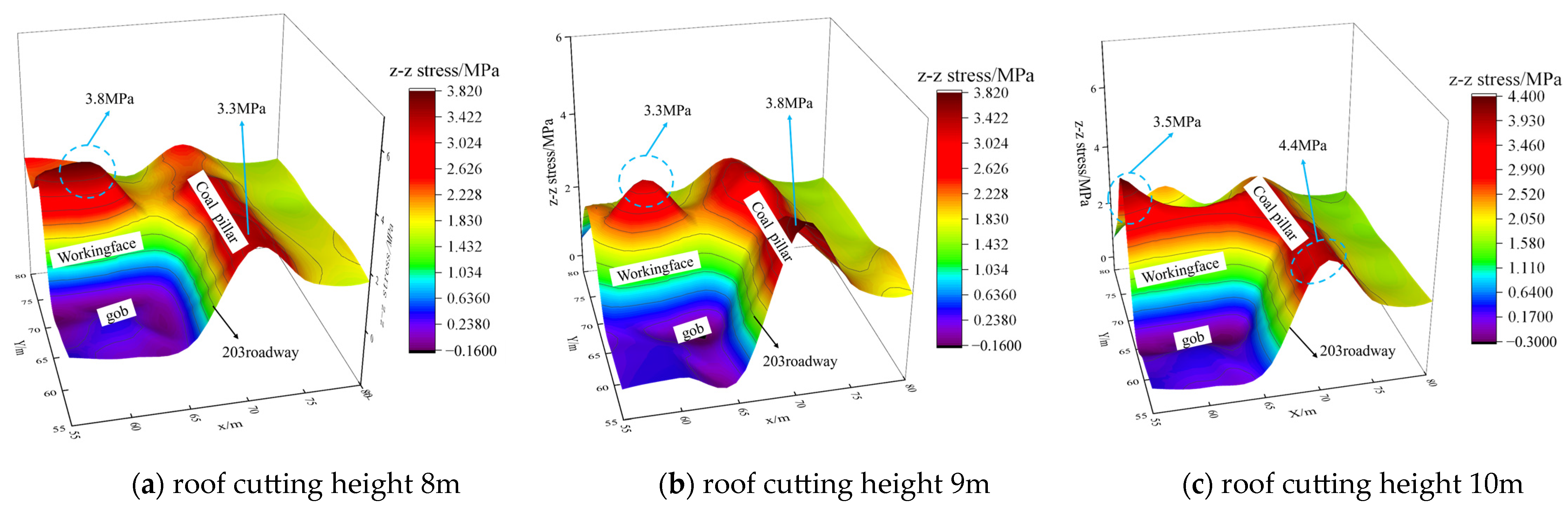
4.3.1. Vertical Stress Distribution Law of Surrounding Rock of Roadway with Different Roof Cutting Heights

The stress distribution cloud diagram of the roof at different roof cutting heights is shown in Figure 8. When the roof cutting height is 8 m, the peak abutment pressure of the working face reaches 3.8 MPa and the peak lateral stress of the solid coal pillar reaches 3.3 MPa. The stress around the roadway is in a low-stress state under the action of roof cutting and pressure relief, and there is no stress concentration in the leading working face of the gob-side entry. As the roof cutting height increases to 9 m, the pressure relief effect improves. The peak value of the advanced abutment pressure of the working face is 3.3 MPa. The overburden load carried by the short-arm beam structure of the roof cutting is transmitted to the fixed-constraint end of the solid coal, and the peak value of the side stress of the solid coal pillar increases to 3.8 MPa. When the roof cutting height increases to 10 m, it has exceeded the roof control range of the constant-resistance anchor cable. The stable structure formed by the short-arm beam of the roof cutting and the support body has difficulty bearing the load of the overburden rock. The peak value of the advanced abutment pressure of the working face reaches 3.5 MPa and the peak value of the side stress of the coal pillar reaches 4.4 MPa. There is obvious stress concentration in the advance support section of the roadway.

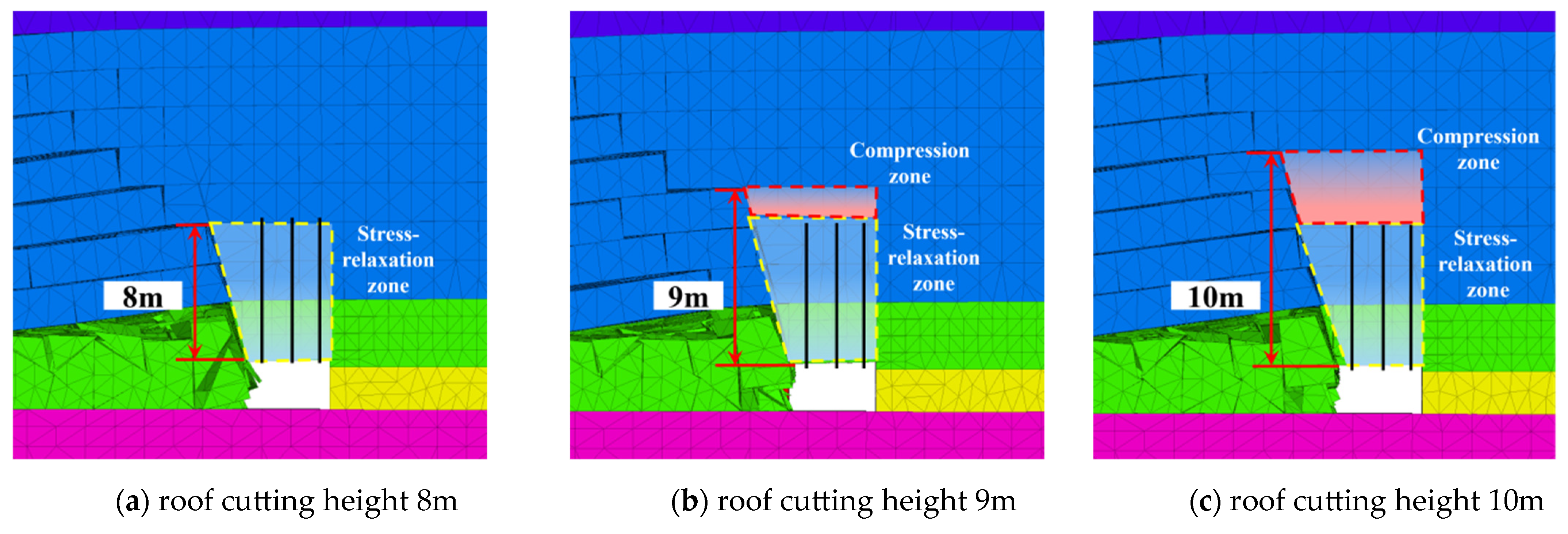
4.3.2. Load-Bearing Characteristics of Roof Cutting ‘Key Structure’

The fixed end of the short cantilever beam structure formed by the roof cutting is the solid coal pillar. The cantilever end is separated from the roof of the gob under the action of the roof cutting of the dense drilling. The structure protects the roof of the roadway from the influence of the roof rotation and subsidence of the gob. The short cantilever beam and the roof constant-resistance anchor cable together form the ‘key structure’ for roof control. As shown in Figure 9a, when the roof cutting height is less than the roof control height of the constant-resistance anchor cable, the constant-resistance anchor cable can anchor the ‘key structure’ and the overlying strata, but when the roof cutting height is greater than the roof control height of the constant-resistance anchor cable, as shown in Figure 9b,c, the roof strata exceeding the roof control height are deformed under the action of roof cutting. At this time, the anchor cable not only bears the weight of the ‘key structure’ but also bears the load applied by the deformation of the overlying roof.
Comparing the stress concentration characteristics of coal pillars under different roof cutting heights, as shown in Figure 10, when the roof cutting height is 8 m, the peak value of the lateral stress of the coal pillar is 3.3 MPa, the influence range of the lateral stress is 8.2 m and the average load-increase coefficient is 1.82; when the roof cutting height is 9 m, the peak value of the lateral stress of the coal pillar is 3.8 MPa, the influence range of the lateral stress is 9.3 m and the average load-increase coefficient is 2.18. When the roof cutting height is 10 m, the peak value of the lateral stress of the coal pillar is 4.4 MPa, the influence range of the lateral stress is 9.6 m and the average load-increase coefficient is 2.73. It can be seen that when the roof cutting height exceeds the bearing range of the ‘key structure’ of the roof control, the stress concentration will occur on the side of the solid coal pillar (the fixed end of the short cantilever beam), and the stress influence range and the load-increase coefficient are positively correlated with the increase of the roof cutting height. Based on the above analysis, 8 m is selected as the optimal roof cutting height.

4.4. Numerical Simulation of Cutting Angle

4.4.1. Vertical Stress Distribution Law of Surrounding Rock of Roadway with Different Roof Cutting Angles

According to scheme II, the roof cutting angle is numerically simulated, and the influence of different roof cutting angles on the vertical stress distribution law of roadway surrounding rock is analyzed, as shown in Figure 11. When the roof cutting angle is 10°, the peak stress of the solid coal pillar side is 4.1 MPa, the peak abutment pressure of the working face is 3.2 MPa and the roadway is in a low-stress environment. When the roof cutting angle is 15°, the peak lateral stress of the solid coal pillar is 3.3 MPa and the peak abutment pressure of the working face is 3.8 MPa. When the roof cutting angle is 20°, the lateral cantilever length of the roof increases, and the overlying strata will have an impact on the roof of the roadway when the overlying strata rotate and sink. The peak stress of the solid coal pillar is 4.1 MPa and the peak value of the advanced abutment pressure of the working face increases to 3.7 MPa. The roof of the roadway in the advanced working face also has obvious stress concentration, resulting in the poorest pressure relief effect.

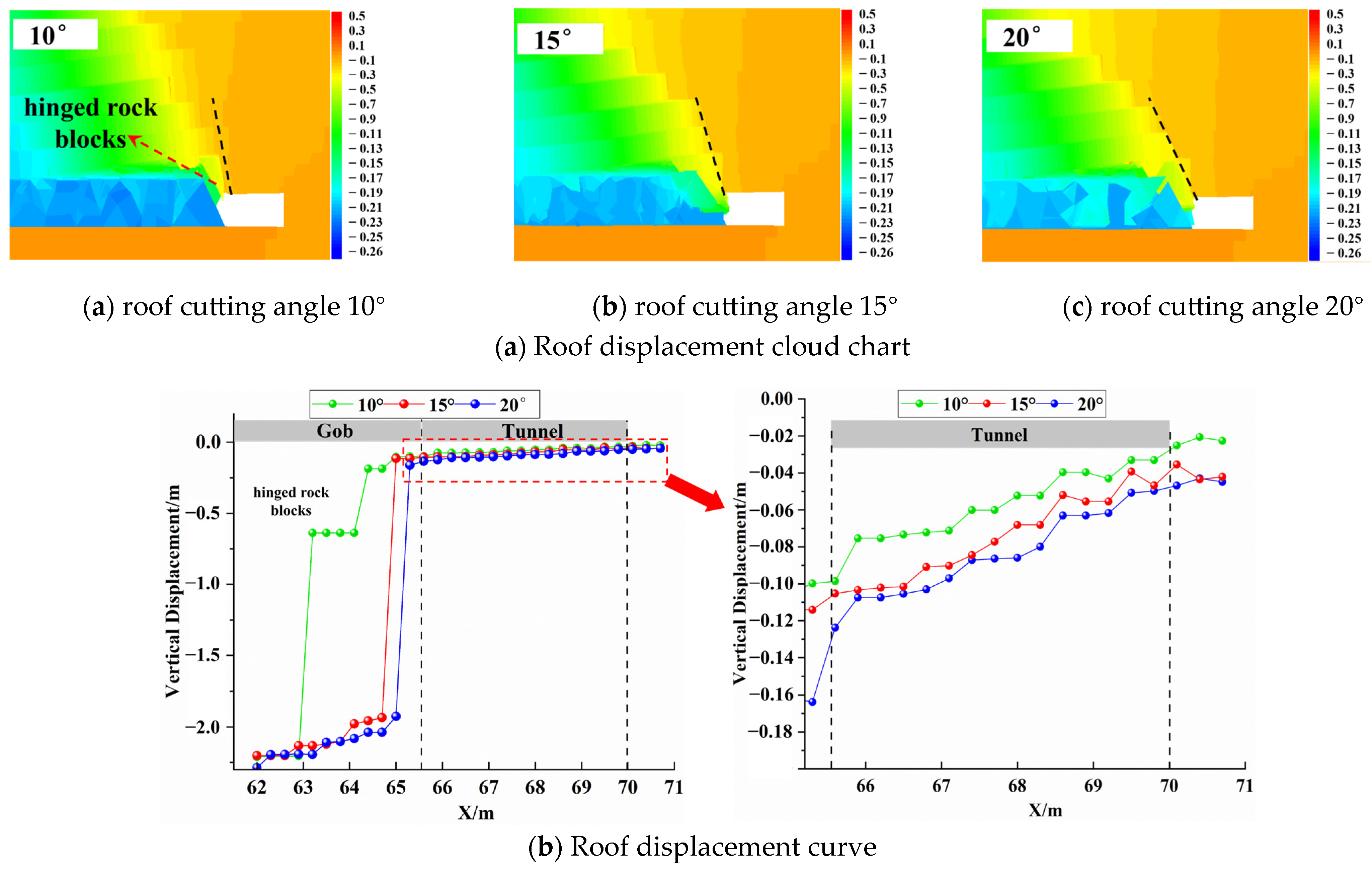
4.4.2. Roof Displacement Distribution Law of Different Roof Cutting Angles

The roof displacement cloud map after the mining of the working face is intercepted, and the roof displacement data are extracted to draw the curve as shown in Figure 12a,b. The different drilling angles will affect the friction between the roof rock blocks. Therefore, it is necessary to compare the vertical displacement of the roof on the side of the gob. It can be seen that when the roof cutting angle is 10°, the cantilever length of the roadway roof becomes shorter. When the roof of the working face rotates and sinks, it is hinged with the roof of the roadway. This part of the rock block is difficult to collapse along the cutting seam, resulting in a suspended roof. At this time, the vertical subsidence of the roof is 0.6 m and the forming effect of the roadway side is poor. When the roof cutting angle increases to 15° and 20°, the roof subsidence on the goaf side is 2.13 m and 2.19 m, respectively, indicating that the increase of the roof cutting angle can effectively reduce the friction between the roof rock blocks, which is conducive to cutting off the roof.
The roof subsidence of the roadway under different roof cutting angles is compared. When the roof cutting angle is 10°, the maximum roof subsidence is 0.09 m. When the roof cutting angle is 15°, the roof subsidence is 0.10 m; when the roof cutting angle is 20°, the cantilever length of the roof increases, and the roof rotation of the working face has an impact on the roof of the roadway, and the roof subsidence increases to 0.13 m. The roof displacement shows the regional characteristics of ‘the largest on the top cutting side, the second in the middle of the roadway, and the smallest on the side of the solid coal pillar’.
Based on the above analysis, when the roof cutting angle is small, the friction between the roof rock blocks is large, and the rock blocks are hinged and difficult to collapse during the rotary sinking process. When the roof cutting angle is large, the increase of the lateral cantilever length of the roof affects the pressure relief effect of the surrounding rock of the roadway, and the subsidence of the roadway roof increases. Therefore, the optimal angle of roof cutting is 15°.

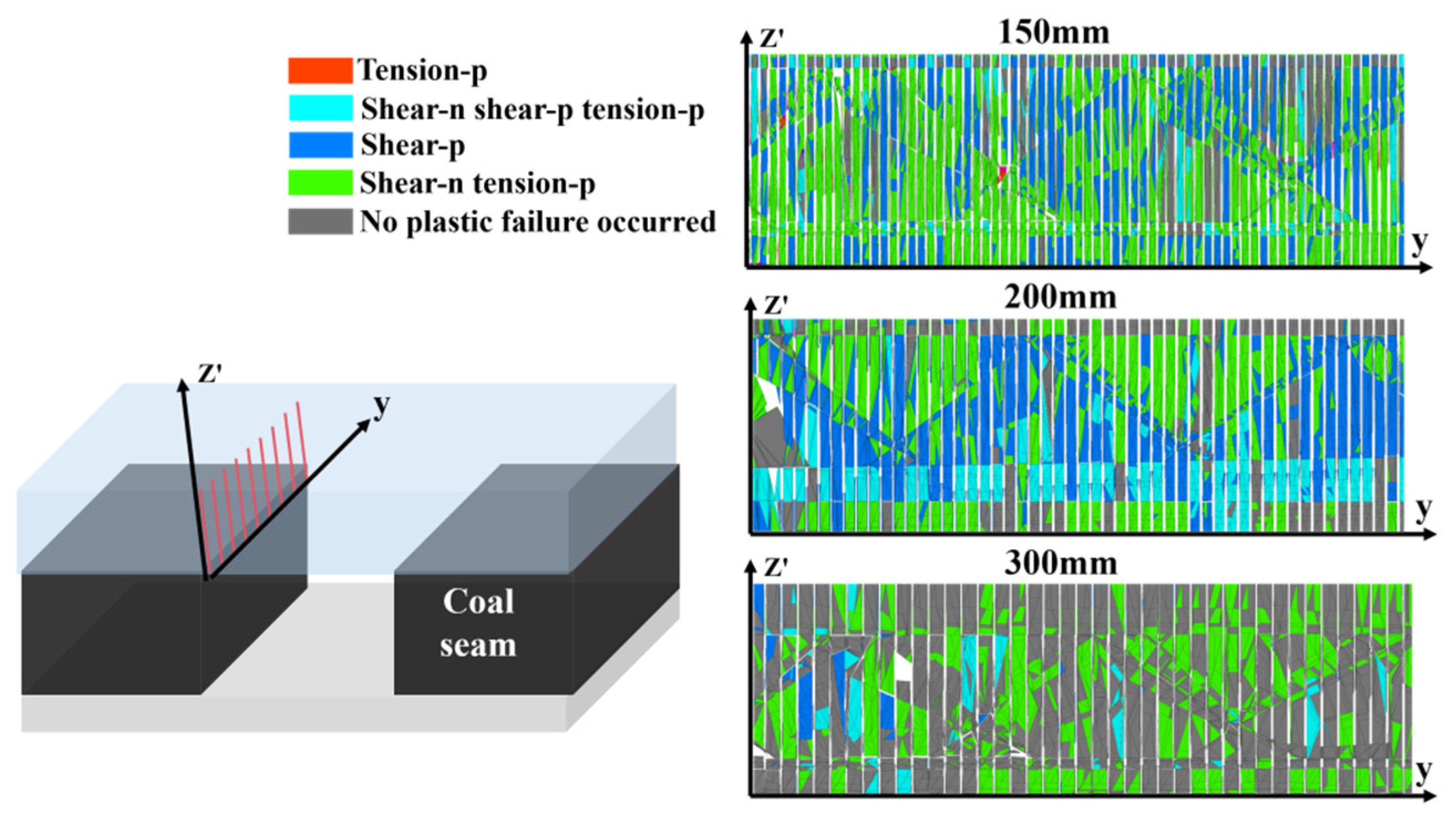
4.5. Numerical Simulation of Borehole Spacing

After determining the parameters of the roof cutting height and roof cutting angle, the influence of different borehole spacings on the effect of roof cutting and pressure relief of dense drilling is compared and analyzed, and the optimal borehole spacing is further determined. The weakening effect of dense boreholes on the roof is affected by the advance abutment pressure. The plastic zone distribution between holes is shown in Figure 13 when the hole spacings are 150 mm, 200 mm and 300 mm, respectively, in the range of 15 m in the advance working face along the cutting line. The penetration rate ζp of plastic failure between dense drilling on the roof is used as the evaluation index to analyze the influence of hole spacing on the roof cutting effect. The ratio of the area Sp of the plastic failure area to the total area Sc of the borehole cutting section is defined as the penetration rate.
ζ p = ( S p / S c ) × 100 %
The number of pixels of tensile and shear failure in the plastic zone cloud map is counted, and the plastic penetration rate between holes with different hole spacing is counted by Equation (34). As shown in Figure 14, when the hole spacing is 150 mm, the plastic zone between holes is the most developed, and the penetration rate ζp is 72.9%. When the borehole spacing is 200 mm, the penetration rate ζp is reduced to 69.1%. When the borehole spacing is 300 mm, the development degree of the plastic zone between boreholes is the lowest, and the penetration rate ζp is 39.0%. With the increase in hole spacing, the degree of weakening of roof strength by roof cutting drilling decreases, and the proportion of tensile failure is greater than that of shear failure, indicating that the process of weakening the roof by dense drilling is dominated by the tensile strength of the rock mass.
Through the above analysis, it can be concluded that when the aperture is determined, the smaller the hole spacing is, the higher the development degree of the plastic zone between the holes is, and the better the weakening effect of the borehole on the roof is. However, the excessive weakening of the roof strength has higher requirements for the roof support at the end and the support of the leading section of the roadway, and the reduction of the hole spacing greatly increases the strength of the on-site construction. Therefore, the optimal hole spacing is 200 mm.

5. Field Engineering Practice

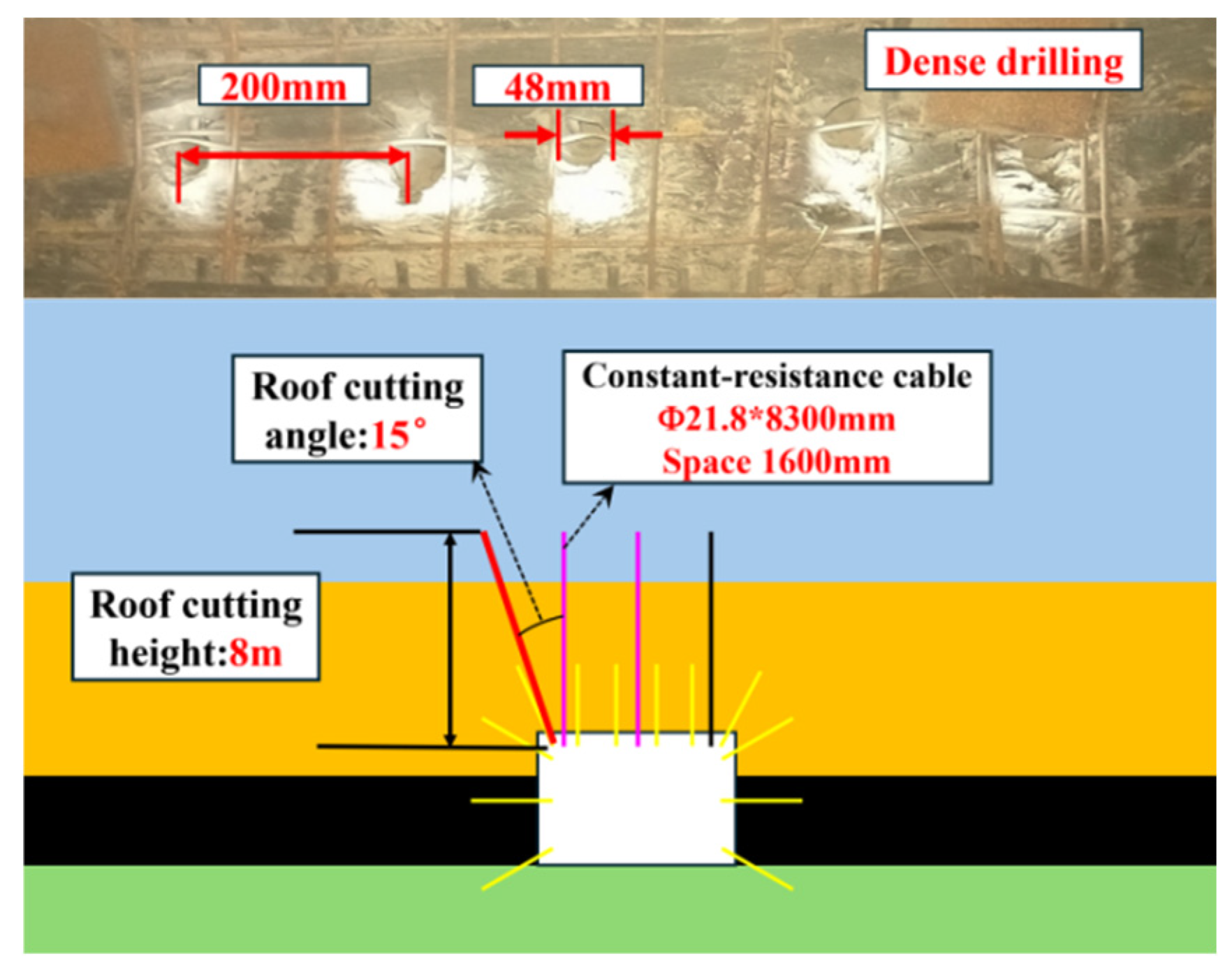
5.1. Dense-Drilling Roof Cutting Layout Scheme

Following comprehensive theoretical analysis and numerical simulation comparison, the key parameters of dense-drilling roof cutting are determined: the roof cutting height is 8 m; the cutting angle is 15°; the diameter of the borehole is 48 mm; the center distance of the borehole is 200 mm. In order to avoid the influence of the equipment at the end of the roadway, the dense drilling construction is 50 m ahead of the working face, and the drilling construction operation is parallel to the working face to ensure that the roadway can be supported in time. The layout scheme of roof-cutting dense drilling is shown in Figure 15.

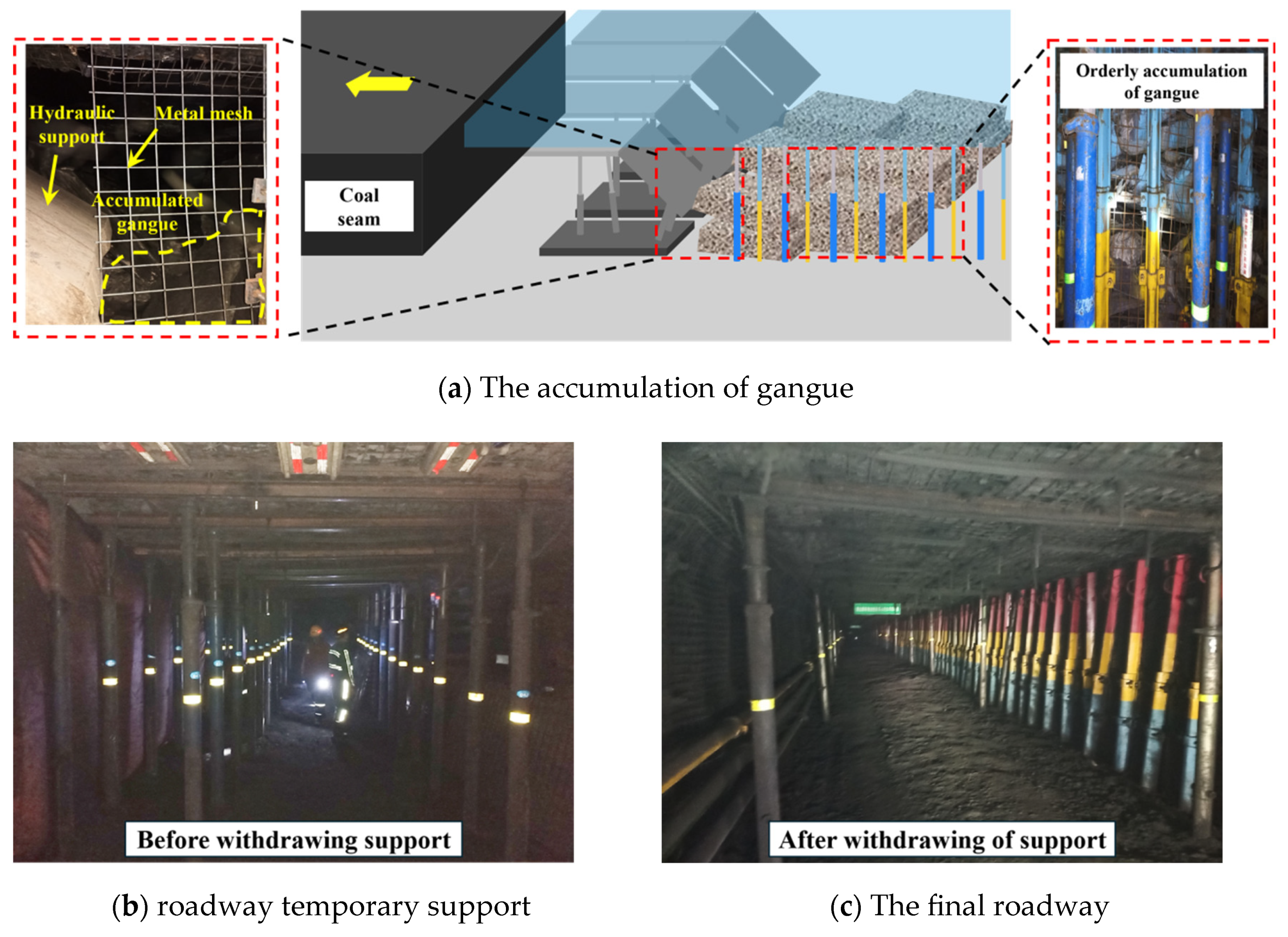
5.2. Engineering Practice Effect

In order to verify the effect of roof cutting by dense drilling, four monitoring stations (1#, 2#, 3#, 4#) were arranged within 150 m of the roof cutting test section of the transportation roadway in the 203 working face, with an interval of 50 m. Figure 16a is the layout of the monitoring points of the working face, and the roof deformation of the roadway at each monitoring point is shown in Figure 16b–e.
By analyzing the data of the four monitoring points, the average subsidence of the roof on the cutting side is 176 mm, the average subsidence in the middle of the roof is 127 mm, and the average subsidence of the roof on the side of solid coal pillar is 60 mm.
Figure 17 is the actual photograph of the site after the roof cutting of the retaining roadway, as shown in Figure 17a: the roof can collapse and fill the gob over time, after the mining of the working face, and the roof cutting effect is better. The gangue did not have an impact on the gangue retaining and supporting objects beside the roadway, and the on-site pressure situation was alleviated. The roof is complete, and no bolt or cable failure occurs. The entry retaining is completed after the single support of the withdrawal entry retaining section, as shown in Figure 17b,c, and entry retainment is effective.

6. Conclusions

(1) The key to gob-side entry retaining technology with intensive borehole roof cutting is to determine reasonable roof cutting parameters (roof cutting height, roof cutting angle, aperture and hole spacing). The control mechanism of each parameter on the roof is analyzed and the numerical simulation is obtained:
① When the borehole cannot penetrate the basic roof strata, the greater the roof cutting height, the easier it is to break the roof, but a higher roof cutting height is not necessarily better. When the roof cutting height exceeds the roof control height of the constant-resistance anchor cable, the peak stress, influence range and load-increase coefficient of the coal pillar side increase, and stress concentration is formed in the advanced section of the roadway. According to the theory of broken expansion, the height of the cutting top is calculated to be H > 7.3 m.
② When the roof cutting angle is small, the roof of the gob is hinged with the roof of the roadway, and the roadway forming effect is poor. Increasing the roof cutting angle increases the lateral cantilever length of the roof, and the rotation of the roof in the gob will increase the roof subsidence of the roadway. A cutting angle of θ ≥ 11.9° was calculated.
③ The large aperture can increase the normal stress and shear stress on the section of the borehole. The theoretical calculation shows that the hole diameter is greater than 40 mm, and the hole diameter of 48 mm is selected according to the drilling construction standard.
④ When the aperture is 48 mm, the hole spacing should not exceed 166 mm. The smaller the hole spacing is, the higher the degree of roof weakening; it also increases the difficulty of construction and has high requirements for end support. The increase in hole spacing is not conducive to the penetration of the drilling plastic zone, and the weakening degree of the roof is limited.
(2) The optimal scheme of dense-drilling roof cutting is determined: a roof cutting height of 8 m; a cutting angle of 15°; a borehole diameter of 48 mm; drilling spacing at 200 mm. The engineering practice application was carried out at the 203 working face of the Ruineng Coal Mine. During the test, the deformation of the surrounding rock of the roadway was controllable, and the size of the roadway met the reuse conditions. The results confirm that the key parameter determination method is effective and the dense-drilling roof cutting and pressure relief gob-side entry retaining is feasible.

Author Contributions

D.L.: Conceptualization, Supervision, Project Administration and Funding acquisition. S.C.: Writing, Original Draft, Conceptualization, Methodology, Software, Validation, Data Curation, Formal analysis. H.Y.: Software, Supervision, Resources, Project Administration, Data Curation. J.Y.: Conceptualization, Supervision, Resources, Project Administration, Validation. Y.Y.: Investigation, Conceptualization, Resources, Project Administration, Formal Analysis. S.L.: Theoretical Analysis, Methodology, Investigation. B.H.: Theoretical Analysis, Methodology, Investigation. P.X.: Conceptualization, Investigation, Data Curation, Supervision. All authors have read and agreed to the published version of the manuscript.

Funding

This research was supported by the Program of National Natural Science Foundation of China (Grant number: 52274137); the Program of National Natural Science Foundation of China (Grant number: 52474145); and Supported by the Excellent Youth Science Foundation of Xi’an University of Science and Technology (Grant number: 6310222012).

Institutional Review Board Statement

Not applicable.

Informed Consent Statement

Not applicable.

Data Availability Statement

Data will be made available on request.

Acknowledgments

The authors express their sincere gratitude to Yongchao Dang and Lishuai Chen for their valuable suggestions and assistance during the preparation of this study. Their contributions were instrumental in refining the research methodology and enhancing the quality of the manuscript.

Conflicts of Interest

The authors declare no conflicts of interest. All authors state that the study was conducted without any business or financial relationships that could be interpreted as potential conflicts of interest.

References

  1. Hua, X. Development status and improvement suggestions of gob-side entry retaining support technology in China. Coal Sci. Technol. 2006, 12, 78–81. [Google Scholar]
  2. Hua, X.; Li, C.; Liu, X.; Guo, Y.; Qi, Y.; Chen, D. Review the development status and improvement suggestions of gob side entry retaining technology in China. Coal Sci. Technol. 2013, 51, 128–145. [Google Scholar]
  3. He, M.; Song, Z.; Wang, A.; Yang, H.; Qi, H.; Guo, Z. Longwall mining roof cutting short wall beam theory and its 110 method-the third mining science and technology change. Coal Sci. Technol. 2017, 11, 1–9. [Google Scholar]
  4. He, M.; Gong, W.; Wang, J.; Qi, P.; Tao, Z.; Du, S.; Peng, Y. Development of a novel energy-absorbing bolt with extraordinarily large elongation and constant resistance. Int. J. Rock Mech. Min. Sci. 2014, 67, 29–42. [Google Scholar] [CrossRef]
  5. Zhang, G.; He, M.; Yu, X.; Huang, Z. Study on the technology of non-pillar mining in the protective layer of Baijiao Mine. Min. Saf. Eng. 2011, 28, 511–516. [Google Scholar]
  6. Sun, X.; Liu, X.; Liang, G.; Wang, D.; Jiang, Y. Study on key parameters of gob-side entry retaining with roof cutting and pressure relief in thin coal seam. J. Rock Mech. Eng. 2014, 33, 1449–1456. [Google Scholar]
  7. He, M.; Chen, S.; Guo, Z.; Yang, J.; Gao, Y. Structural control of surrounding rock of gob-side entry retaining with roof cutting and pressure relief and its engineering application. J. China Univ. Min. Technol. 2017, 46, 959–969. [Google Scholar]
  8. He, M.; Gao, Y.; Yang, J.; Guo, Z.; Wang, E.; Wang, Y. Study on energy-gathering cutting technology of self-forming roadway without coal pillar and its influence on stress evolution of surrounding rock. J. Rock Mech. Eng. 2017, 36, 1314–1325. [Google Scholar]
  9. Lin, J.; Guo, K.; Sun, Z.; Wang, T. Study on the timing of hydraulic fracturing roof cutting and pressure relief fracturing in strong dynamic pressure roadway. J. Coal 2021, 46, 140–148. [Google Scholar]
  10. Sun, Z.; Zhang, Z.; Wang, Z.; Wang, T.; Fu, Y. Application of hydraulic fracturing roof cutting and pressure relief technology in large mining height roadway. Coal Sci. Technol. 2019, 47, 190–197. [Google Scholar]
  11. Wu, W.; Wang, T.; Bai, J.; Liu, J.; Wang, X.; Xu, H.; Feng, G. Failure Characteristics and Cooperative Control Strategies for Gob-Side Entry Driving near an Advancing Working Face: A Case Study. Processes 2024, 12, 1398. [Google Scholar] [CrossRef]
  12. Sun, X.; Qi, Z.; Zhang, Y.; Li, Z.; Xie, C.; Yang, J.; Ding, J.; He, L. Characteristics and Control Measures of Deep and Shallow Dense Drilling in Roadway for Pressure Relieving by Cutting Roof. Min. Metall. Explor. 2024, 41, 787–803. [Google Scholar] [CrossRef]
  13. Liu, Y.; Kang, T.; Zhang, L.; Zhu, W.; Zhang, G.; Wang, J. Research on roof cutting mechanism and parameter optimization of non-blasting dense drilling. Min. Res. Dev. 2023, 43, 34–39. [Google Scholar]
  14. Zhao, Y.; Xie, H.; Yao, Q. Research on roof cutting and pressure relief roadway protection technology of dense drilling in Songxinzhuang. Coal Mine. Coal Eng. 2023, 55, 45–51. [Google Scholar]
  15. Wang, M.; Zheng, D.; Wang, X.; Xiao, T.; Shen, W.; Song, Z. Weakening deformation characteristics and creep control of surrounding rock in deep roadway drilling pressure relief. J. Min. Saf. Eng. 2019, 36, 437–445. [Google Scholar]
  16. Ma, B.; Deng, Z.; Zhao, S.; Li, S. Analysis of mechanism and influencing factors of rock burst prevention and control by borehole pressure relief. Coal Sci. Technol. 2020, 48, 35–40. [Google Scholar]
  17. Jia, C.; Jiang, Y.; Zhang, X.; Wang, D.; Luan, H.; Changsheng, W. Indoor and numerical experimental study on pressure relief mechanism of large diameter borehole. J. Geotech. Eng. 2017, 39, 1115–1122. [Google Scholar]
  18. Ding, K.; Zhang, H.; Wang, L.; Guo, J.; Meng, Y. Damage evolution characteristics of coal body and strength weakening mechanism of borehole surrounding rock in deep roadway. Coal J. 2024, 49, 4798–4821. [Google Scholar]
  19. Ma, J.-Q.; Li, X.-H.; Yao, Q.-L.; Xia, Z.; Xu, Q.; Shan, C.-H.; Sidorenko, A.; Aparin, A. Numerical simulation on mechanisms of dense drilling for weakening roofs and its application in roof control. J. Cent. South Univ. 2023, 30, 1865–1886. [Google Scholar] [CrossRef]
  20. Wang, M.; Wang, X.; Xiao, T. Deep roadway drilling pressure relief mechanism and key parameter determination method and application. Coal J. 2017, 42, 1138–1145. [Google Scholar]
  21. Li, D.; Zhang, J.; Zheng, L.; Wang, S.; Wang, W.; Huang, Z. Dense drilling weakening bottom layered roof gob-side entry retaining technology. Coal Mine Saf. 2022, 53, 111–118. [Google Scholar]
  22. Sun, B.-J.; Hua, X.-Z.; Zhang, Y.; Yin, J.; He, K.; Zhao, C.; Li, Y.; Sun, Y. Analysis of Roof Deformation Mechanism and Control Measures with Roof Cutting and Pressure Releasing in Gob-Side Entry Retaining. Shock Vib. 2021, 2021, 6677407. [Google Scholar] [CrossRef]
  23. Wang, Q.; Jiang, Z.; Jiang, B.; He, M.; Yang, J.; Xue, H. Ground Control Method of Using Roof Cutting Pressure Release and Energy-Absorbing Reinforcement for Roadway with Extra-Thick Hard Roof. Rock Mech. Rock Eng. 2023, 56, 7197–7215. [Google Scholar] [CrossRef]
  24. Han, Z.; Dou, L.; Gong, S.; Kan, J.; Chen, S.; He, X. Mechanism of rock burst in deep gob-side entry based on dynamic and static stress: A case study. Geomat. Nat. Hazards Risk 2023, 14, 2271636. [Google Scholar] [CrossRef]
  25. Li, X.; Liu, S.; Fu, M.; Peng, B.; He, Y. Research and Application of Key Parameters Influencing Factors of Dense Drilling Roof Cutting Pressure Relief. Coal Sci. Technol. 2023, 51, 243–253. [Google Scholar]
  26. Liu, S.; Li, X.; Zhu, W.; Fu, M.; Zhang, D.; Peng, B. Roof cutting mechanism and key parameter determination method of dense drilling in gob-side entry retaining. Coal Sci. Technol. 2024, 52, 23–33. [Google Scholar]
  27. Wang, Q.; Wei, H.; Jiang, B.; Wang, X.; Sun, L.; He, M. High pre-tension reinforcing technology and design for ultra-shallow buried large-span urban tunnels. Int. J. Rock Mech. Min. Sci. 2024, 182, 105891. [Google Scholar] [CrossRef]
  28. Liang, S.; Zhang, L.; Ge, D.; Wang, Q.; Feng, G. Study on Pressure Relief Effect and Rock Failure Characteristics with Different Borehole Diameters. Shock Vib. 2021, 2021, 3565344. [Google Scholar] [CrossRef]
  29. Jiang, B.; Ma, F.; Gao, H.; Wang, Q.; Cai, S.; Zhang, C.; Bian, Z.; Liu, G. The response mechanism and testing method of the rock elastic modulus while drilling. Geomat. Nat. Hazards Risk 2024, 15, 2354498. [Google Scholar] [CrossRef]
  30. MT/T 984-2006; Coal Industry Standard of the People’s Republic of China MT/T984-2006, Diamond Composite Anchor Bit for Coal Mine. Xi’an Branch of CCRI: Xi’an, China, 2006.
  31. Guo, Z.; Zhao, Y.; Yang, D.; Guo Ji Yin, S.; Qiu, X. Research on roof deformation mechanism and control technology of cross-fault roof cutting and pressure relief self-forming roadway. Coal Sci. Technol. 2024, 52, 14–28. [Google Scholar]
Figure 1. Working face layout and surrounding rock structure peep results. Seven borehole peeping points were arranged and named 1 #~7 #.
Applsci 15 02685 g001
Figure 2. Support section of roadway and borehole histogram.
Applsci 15 02685 g002
Figure 3. Stress analysis of non-penetrated surface during partial roof cutting.
Applsci 15 02685 g003
Figure 4. The relationship between σw and h1.
Applsci 15 02685 g004
Figure 5. Stress analysis of key block of roof cutting.
Applsci 15 02685 g005
Figure 6. Mechanical model of roof of dense-drilling roof cutting roadway.
Applsci 15 02685 g006
Figure 7. Numerical calculation model.
Applsci 15 02685 g007
Figure 8. The stress distribution law of roadway surrounding rock under different roof cutting.
Applsci 15 02685 g008
Figure 9. The bearing characteristics of ‘key structure’ with different roof cutting heights.
Applsci 15 02685 g009
Figure 10. Stress concentration characteristics of coal pillar under different roof cutting heights.
Applsci 15 02685 g010
Figure 11. The stress distribution law of roadway surrounding rock under different roof cutting angles.
Applsci 15 02685 g011
Figure 12. Roof displacement distribution law of roadway with different roof cutting angles.
Applsci 15 02685 g012
Figure 13. Plastic failure law in boreholes with different borehole spacing.
Applsci 15 02685 g013
Figure 14. Different aperture penetration rates ζp and plastic failure statistics.
Applsci 15 02685 g014
Figure 15. Layout scheme of roof-cutting dense drilling.
Applsci 15 02685 g015
Figure 16. 203 transport roadway roof deformation monitoring curve.
Applsci 15 02685 g016
Figure 17. Scene photographs.
Applsci 15 02685 g017
Table 1. Physical and mechanical parameters of rock mass.
NameLithologic CharactersVolumetric Weight/(kg/m3)Bulk Modulus/(GPa)Shear Modulus/(GPa)Internal Friction Angle/(°)Cohesion/(MPa)
Overlying strataSiltstone246010.838.13382.75
Main roofFine sandstone287321.0113.52423.20
Immediate roofMudstone24635.743.44301.25
Coal seam2# Coal13804.912.01321.25
Immediate floorMudstone24616.083.47301.20
Main floorSandy mudstone25102.562.36362.16
Table 2. The relationship between the hole spacing, the radius of the plastic zone and the diameter.
2R4855657594
R0/mm8395112129162
D/mm166190224258324
Table 3. Mechanical parameters of joints.
Lithologic CharacterCohesion/MPaAngle of Internal Friction/(°)Joint Normal Stiffness/(Gpa·m−1)Joint Shear Stiffness/(Gpa·m−1)
Siltstone2.7151.051.35
Fine sandstone1.8120.730.48
Mudstone1.1200.650.25
2# Coal seam0.6100.330.12
Mudstone1.1200.650.25
Sandy mudstone1.3160.750.72
Table 4. Numerical simulation scheme.
Serial NumberSchemeVariableInvariant
IChange the roof cutting height8 mRoof cutting angle 15°
Diameter of borehole 48 mm
Hole spacing 200 mm
9 m
10 m
IIChange the roof cutting angle10°Roof cutting height 8 m
Diameter of borehole 48 mm
Hole spacing 200 mm
15°
20°
IIIChange the hole spacing150 mmRoof cutting height 8 m
Diameter of borehole 48 mm
Roof cutting angle 15°
200 mm
300 mm
Disclaimer/Publisher’s Note: The statements, opinions and data contained in all publications are solely those of the individual author(s) and contributor(s) and not of MDPI and/or the editor(s). MDPI and/or the editor(s) disclaim responsibility for any injury to people or property resulting from any ideas, methods, instructions or products referred to in the content.

