1. Introduction
The planing hull, extensively utilized as a specialized type of high-speed vessel, differs from conventional hull forms. Such a scheme utilizes the principle of planing on the lifting surface to reduce the wetted area and thus achieve a drag reduction effect at high speeds; hence, the planing hull exhibits superior high-speed performance. Early design efforts for planing hulls relied mainly on model testing results [
1]. Up until now, extensive tests have been performed on various hull forms, and hydrodynamic performance diagrams and empirical formulas have been derived from a set of test results. Based on these findings, suitable parent hulls have been selected for modified designs, the results of which depend on the designer’s personal experience and subjective judgment. With advances in computer processing power and the development of simulation techniques, the simulation-based design (SBD) method has been broadly utilized in the hull design process due to its flexibility, efficiency, and cost-effectiveness. Parametric modeling of hull forms enables rapid generation of hull models on a computer and forms an essential foundation for hull optimization using SBD.
In general, there are two main categories of parametric design approaches for hull design. One approach involves modifying existing hull surfaces by designing transformation parameters, such as the free-form deformation (FFD) method, the so-called Lackenby transformation method, and the morphing approach [
2,
3]. These methodologies depend on the selection of an initial hull shape, which leads to a limited design space, and many transformation parameters have no physical meaning. Another approach is full-parametric modeling, which constructs point–curve–surface entities based on given design parameter constraints without relying on the initial hull shape. This design approach achieves a complete definition of the entire hull geometry solely through the design parameters.
In the 1970s, Kuiper introduced mathematical methods for representing ship hull surfaces [
4]. Since the 1990s, numerous investigators have conducted research on parametric modeling of hull forms. Harries and coworkers [
5,
6,
7] proposed a parametric design method and developed a corresponding design software, CAESES. CAESES is a powerful design software widely used in the field of hull design, which can assist in defining geometric features, optimizing design parameters, and generating high-quality hull models with its advanced algorithms and intuitive interface. This approach can be effectively employed to optimize the hydrodynamic performance of ship forms. Zhang et al. [
8] and Zhang [
9] applied the NURBS theory to determine longitudinal characteristic curves and employed optimization methods to generate waterlines, thereby obtaining the hull surface. Lu [
10] utilized NURBS functions to represent the surfaces of ship hulls, focusing on key issues in ship design. Kostas et al. [
11] employed T-splines in the Rhino modeling environment to construct hull surfaces with a bulbous bow that obtained second-order continuity, except for extraordinary points. Mancuso [
12] applied parameter constraints to establish keel lines and waterlines for the sail hull and used B-spline surfaces for parametric modeling of the fairing. Zhou et al. [
13] proposed a NURBS-based parametric method for waterline ship surfaces, which parameterizes the ship hull surface by classifying geometric feature factors and designing feature curves. The NURBS techniques were adopted for the geometric modeling of hull curves and surfaces, allowing hull deformation driven by geometric feature parameters, and a corresponding software package was also developed. Paérez [
14,
15,
16] implemented B-spline methods to achieve parametric modeling of a variety of ships, including waterline ships, planing hulls, and small-waterline catamarans. Khan et al. [
17] divided the hulls into three segments and performed parametric modeling for each segment to produce various ship forms.
The goal of parametric modeling is to use concise and physical design parameters to generate ship forms. Too few design parameters lead to insufficient design space, while too many make the method too complicated and lose the importance of parametric modeling. Therefore, in order to develop an applicable parametric method for optimizing the hydrodynamic performance of the hull, the geometric features related to the hull form are here investigated during the hull hydrodynamic study.
In previous investigations, empirical equations were established using parameters such as the Froude number, beam/length ratio, and deadrise angle to evaluate the performance of planing hulls [
1]. In recent years, more scholars have focused on the finer geometric features of planing hulls and conducted research on their hydrodynamic performance. Pacuraru et al. [
18] performed computational fluid dynamics (CFD) investigations on the total resistance, sinkage, and trim angle of the planing hull by establishing calculation models for the hydrodynamic performance of seven boat types. They examined the effect of various features, including spray rails and chines, on the performance of the planing hull. Ma [
19] utilized a monohull planing model as the main form to establish a double chine planing hull and analyzed the effects of the deadrise angle and spray rail width between the two chines as design parameters on both the total resistance and wave resistance. Zhao et al. [
20] developed a prediction model for the residual resistance of a planing hull via a random forest model with six variables, including the geometric characteristics of the hull such as the length/beam ratio (
L/
B), prismatic coefficient (
Cp), and Froude number (
Fr). Tran et al. [
21] established a resistance objective function incorporating three major
F-parameters—the static load coefficient, longitudinal center of gravity position relative to the beam (
LCG/
B), and deadrise angle (
β)—and utilized an approximate optimization model to obtain the optimal resistance hull form for a high-speed passenger boat. Matveev [
22] considered non-prismatic hull forms with variable and negative deadrise angles in the hydrodynamic modeling approach for planing hulls. Schachter et al. [
23] proposed a special approach, the so-called “virtual prisms”, to evaluate the dynamic equilibrium of the planing hull on the water surface and then applied it to hull forms with varying deadrise angles along the length of the boat. Kim et al. [
24] conducted experimental and CFD investigations on a deep-V hull form and analyzed the effect of the bow shape on the resistance and seakeeping performance.
In general, the construction of the planing surface, particularly the distribution of deadrise angles and the profile shape, plays a vital role in the hydrodynamic performance of the planing hull. However, current design approaches for planing hulls rarely consider the deadrise angle as a design parameter. Therefore, this study aims to incorporate crucial design parameters, including longitudinal functions for the deadrise angle of the planing surface, to establish a modeling approach that focuses on key geometric features, especially the planing surface.
The main goals of this article can be summarized as follows: (i) In response to the need for optimizing the hydrodynamic performance of planing boats, appropriate design parameters with high flexibility and independence are reasonably introduced. Therefore, the designer can freely choose them for local or global optimization; (ii) a modeling approach based on B-spline theory is proposed. Using the design parameters as constraints, a set of equations is appropriately constructed to generate the main feature curves and sections (station curves) of the hull, which are solved to form the main frame of the vessel. To this end, the hull surface is constructed by employing B-spline surface interpolation. The modeling approach is implemented in a programming environment, and hull models are established to validate the practicality of the proposed approach.
3. Description of the Method
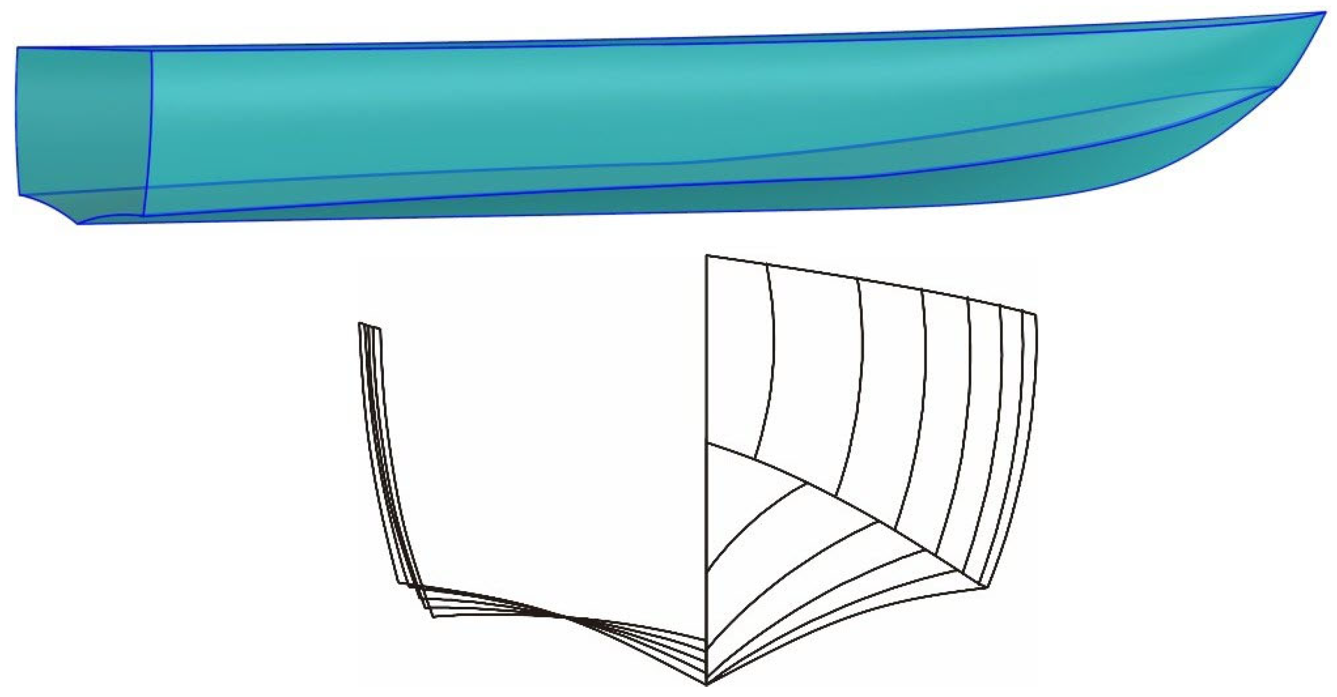
The typical body contour curves of a monohull unstepped planing hull with spray rails are depicted in
Figure 2. The hull coordinate system
O-
xyz is utilized, where the
x-axis extends from the stern to the bow, the
y-axis is horizontal and points towards the left side of the craft, and the
z-axis is vertical, pointing upwards. The origin is located on the vertical line, which is determined by intersecting the plane of the stern and the longitudinal section of the craft, and it is at the same height as the forefoot point at the keel. From bottom to top, the presented curves are the keel curve, inner and outer chine curves, and sheer curves.
The projection of the feature curves of the planing hull in the plane view and the lateral view are shown in
Figure 3. The inner chine curve and the keel curve define the boundary of the planing surface. These curves determine the horizontal projection area, deadrise angle, maximum beam, longitudinal curvature, and other characteristics of the planing surface. Additionally, the transverse curvature of the surface is determined by the transverse section curve parameters. The inner and outer chine curves possess similar shapes and define the characteristics of the spray rail surface. The space between the outer chine curve and the sheer curve defines the hull side surface, which can be obtained by establishing the frame using the side-view station curves.
Table 2 provides a complete set of design parameters required to define a planing craft.
The modeling procedure is illustrated in
Figure 4. It commences with the keel curve and progresses upwards, establishing a system of equations for the control points of each feature curve and station curve. These equations are subsequently solved to form the wireframe, which is then appropriately interpolated to generate the hull surface.
3.1. Definition of the Keel Curve
The keel curve of the planing hull is shown in
Figure 5. This curve can be divided into three segments based on different longitudinal features, with C
1 continuity maintained at the joint points
Pk1 and
Pk3. The first segment (i.e., the bottom straight section) is located near the stern of the hull. Some boat designs employ a certain longitudinal incline in this segment to facilitate the arrangement of propulsion devices, which can be constructed using straight-line segments based on the endpoints. The second segment (i.e., bow curved lift section) of the keel curve is located in the bow’s planing surface lift section. It starts at point
Pk1, passes through point
Pk2, and ends at point
Pk3, exhibiting relatively high curvature. The final segment (i.e., the bow outward section) is positioned at the stem of the ship and shows the tangential continuity at
Pk3 with the second segment.
3.1.1. Definition of the Bow Curved Lift Section
The curved lift section of the bow is mainly related to its navigation performance. The steeply sloping shape allows the bow to lift at low speeds, which is of great advantage for planing. However, from the perspective of spray performance requirements, a smaller angle between the keel curve and the waterline is desirable to improve spray performance. To balance these two requirements, the design of the bow of a planing boat usually possesses a relatively flat shape below the waterline and a steeper shape above the waterline. To represent this curve, a cubic Bézier curve is taken into account, with
Pk1 and
Pk3 as curve endpoints used.
and
were the control points to be solved.
As illustrated in
Figure 6, the chord line
Pk1Pk3 is constructed, and the point
Pk2 represents the furthest point of the curve from the chord
Pk1Pk3. The curve
Sk2(u) satisfies the following conditions: (i) it passes through point
Pk2; (ii) the slope of the curve at point
Pk2 is equal to the slope of the chord line; and (iii) at point
Pk1, it is tangent to the first segment. Therefore, a system of equations can be established and solved to obtain the coordinates of the control points of the curve, as follows:
where
η1 represents the slope of the chord line
Pk1Pk3,
η2 denotes the slope of the tangent vector at point
Pk1, and
upk2 denotes the corresponding curve parameter value at point
Pk2.
upk2 can be calculated by the chord-length parameterization approach.
To express the local geometric relationships in terms of relatively independent design parameters, point
Pk2 should be transformed into a relative position form using parameters
λk1 and
λk2, as in the following form:
In addition, , and where denotes the unit vector perpendicular to nk1. When both parameters λk1 and λk2 are set equal to 0, it can be readily proven that the curve would be equivalent to a quadratic B-spline curve.
3.1.2. Definition of the Bow Outward Section
The outward section of the bow is located at the end of the keel curve, which starts from point
Pk3 and ends at
Pk4 (see
Figure 7). At point
Pk3, it satisfies first-order continuity with curve
Sk2(u). The tangent vector of endpoint
Pk4 makes an angle
αk with the
x-axis, which is appropriately expressed via a quadratic Bézier curve, as given by Equation (13). Further,
denotes the control point that should be suitably determined.
Control point
Ck3 can be evaluated by solving Equation (14), which is established based on the slope constraints at both endpoints, given that the end angle at the design parameter is
αk.
where the slope of the tangent vector at
Pk3 is denoted by
η3, which is evaluated by control point
Ck2 and point
Pk3.
3.2. Definition of the Stations of the Planing Surface
The planing surface plays a pivotal role in the hydrodynamic performance of the watercraft during the planing process. Depending on the vessel type and performance requirements, there are various design forms for the planing surface station curves (see
Figure 8). The angle between the chord line connecting the two endpoints of the planing surface station curve and the horizontal plane is defined as the deadrise angle
θ. Moreover, it is possible to incorporate multiple cross-sectional types and deadrise angles at different longitudinal positions for the same planing hull model. In this way, a series of longitudinal coefficients can be utilized to define the main characteristics of the planing surface.
3.2.1. Definition of the Inner Chine Curve in Plan View
The inner chine curve in plan view is illustrated in
Figure 9, extending from
Pc0 at the stem to
Pc1 at the transom through the widest point
Pcm. A cubic Bézier curve is utilized to represent the chine curve, where
Cc2 and
Cc3 represent the control points to be determined.
The main parameters used for the design geometry are as follows: stern width (
Bt), maximum width of inner chine curve (
Bcm), longitudinal length of inner chine curve (
Lc), end tangent angle (
βc), horizontal projection area of the planing surface (
A), and longitudinal coordinate of the centroid of horizontal projection (
xAc). Since the area and centroid require some integrals to be calculated, it is not convenient to construct linear equations to get control points. By introducing the x-coordinate values
xcm and corresponding curve parameter
ucm values, as well as combining the constraints of terminal tangent angle and maximum width of chine, a system of equations for curve control points can be constructed, as follows:
By solving Equation (16), the control points
Cc2 and
Cc3 can be obtained. By substituting
Cc2 and
Cc3 into Equation (15), curve equation
S(
u) could be appropriately calculated, where
and
represent the
x and
y components of
S(
u). Therefore, both the area
and centroid x-coordinates
can be stated by
xcm and
ucm, as follows:
Considering the design parameters of
A and
xAc, the objective function is constructed as follows:
The non-dominated sorting genetic algorithm II (NSGA-II) [
26] is a widely used multi-objective optimization algorithm that can effectively handle multiple conflicting objectives simultaneously. The NSGA-II is implemented to search for
xcm and
ucm, aiming to minimize the objective function in Equation (19) and satisfy the area and centroid conditions. By substituting the obtained solutions into Equation (16), the numerical solution of the curve control points
Cc2 and
Cc3 can be obtained by satisfying the area and centroid requirements.
3.2.2. Equations and Solution of the Stations of the Planing Surface
Along the longitudinal range [0,
Lc] of the keel curve, equidistant coordinate values are selected. Within each segment, the cubic Bézier curves are utilized to construct the sliding surface station curves as shown by the orange curve in
Figure 10.
For the analysis of the
i-th station, by substituting
xi into the segmented keel curve in Equation (20), the intersection point
Qki of the keel curve and the cross-section can be determined. By substituting
xi into the horizontal projection of the inner chine curve in Equation (15), the corresponding abscissa
yQci of
Qci is evaluated. Hence, the chord length can be evaluated by the following:
li =
yQci/cos(
θi). For ease of analysis, a local coordinate system
Qki-
xiyizi is established, with
Qki as the origin. In this local coordinate system, the
x-axis aligns with the hull coordinate system, and the
y-axis aligns with the chord line. Let the rotation matrix around the
x-axis be denoted as
Rθi. The relationship between the coordinates of an arbitrary point
P in the hull coordinate system and its coordinates
in the local coordinate system
Qki-
xiyizi is as follows:
The
i-th station curve is analyzed in the local coordinate system
Qki-
xiyizi. In this case, with
Qki as the origin, the coordinates of
Qci are (0,
li,0). The control points
C1,i and
C2,i are sought to satisfy the following parameter conditions: at the extremum point
Pmi, the first derivative of the curve’s Z component, Z′(u), is equal to zero, and the z-coordinate at the extremum point
Pmi is denoted as
zpmi. Additionally, the angle between the tangent vectors at both ends and the chord line is denoted by
γci and
γki. The system of equations can be derived as follows:
where the shape coefficients
ks,i and
km,i are introduced to define
upmi and
zpmi since
upmi cannot be obtained via the chord-length parameterization method.
The transverse curvature of the planing surface is determined by the shape coefficients (ks,i and km,i) and the angles (γci and γki). By solving Equation (22), the local coordinate values of the control points are evaluated. By introducing these values to Equation (21), the global coordinate values of C1,i and C2,i are obtained. It can be proven that when the curved shape is either concave or convex, the value of ks,i and km,i can be set equal to 0, resulting in an equivalent quadratic B-spline curve.
3.2.3. Longitudinal Function
In the process of generating the station curves of the planing surface, five groups of parameters are introduced for each station, including the deadrise angle, the endpoint tangent angles (
γki and
γci), and the shape coefficients (
ksi and
kmi). These variables can be obtained by evaluating five longitudinal functions
θ(
x),
γk(
x),
γc (
x),
ks(
x), and
km(
x) at the corresponding
xi values. The longitudinal function
θ(
x) for the deadrise angle of the planing surface is then established using piecewise functions (see
Figure 11). The deadrise angle of the planing surface moderately changes smoothly along the longitudinal direction in the middle and rear sections, which are constructed using linear functions. In the middle and front sections, the deadrise angle of the planing surface exhibits an S-shaped distribution, which is constructed with reference to an S-shaped function:
f(
t) = (1 −
tm)
n (
t = 0~1). This allows us to obtain the deadrise angle, as follows:
The relative shape of the station curves is mainly influenced by γk(x), γc (x), ks(x), and km(x), in addition to θ(x). To meet the design requirements for the lateral bending shape of the planing surface, constant values or simple functions can be utilized for construction. By using constant values, a planing surface with a constant cross-sectional shape can be achieved. Alternatively, the use of straight lines or other simple functions usually results in a gradual change in the planing surface.
3.3. Definition of the Chine Curves
3.3.1. Definition of the Inner Chine
Fitting the discrete points
Qci that were calculated in
Section 3.2.2 can establish the inner chine curve. There are two main methods for fitting 3D curves with discrete points: approximation and interpolation. The approximation method constructs curves with fewer nodes, establishes an overdetermined system of equations, and utilizes algorithms such as least squares to evaluate the curve control points. In the context of this approach, the curve does not entirely pass through the discrete points; hence, this is regarded as an approximate approach. The other method is interpolation, where a specified number of nodes are employed to construct a curve that satisfies the requirement of passing through the discrete points. Therefore, it represents a relatively accurate analytical method. In the present study, a cubic B-spline curve interpolation is employed to establish the inner chine curve in the following form:
In the above relation, the curve is interpolated at the nodes
Qci. In the case of
nk discrete points, the number of nodes on the curve is determined as
nk + 2. The node vector
U = {
u0,
u1, …
un+4} is obtained via the chord-length parameterization method. The interpolation curve interpolates at all nodes with the discrete points
Qci. The nodes at both the beginning and the end should satisfy the following condition:
where
D0 and
Dn represent the first derivative vectors at the beginning and end points of the curve.
By obtaining the diagonal equation system based on the discrete point conditions, as displayed by Equation (27), the control points for the 3D curve of the chine line can be obtained by solving the following set of equations:
3.3.2. Definition of the Outer Chine
The outer chine curve is established with the inner chine curve as the reference (
Figure 12). Let us denote
ni as the unit normal vector at the position of the chine curve in the horizontal plane. To start from the discrete point
Qci, these points on the outer chine curve can be evaluated as follows:
The longitudinal function, denoted as
Wr(
x), can be utilized to calculate the variation of the width of the splash guard along the ship’s length. The spray rail can be designed with a uniform width in the mid-aft section of the hull while gradually tapering and narrowing towards the bow. To construct this function, the multi-segment function composed of straight lines and quadratic functions can be utilized as follows:
The discrete points
Qri on the outer chine curve can be appropriately calculated based on Equation (28). As a result, the control equation for the outer chine curve of the spray rail can be then constructed via the curve interpolation method (as explained in
Section 3.3.1) in the following form:
where
Pri represents the control points of the outer chine curve. Due to the similarity between the inner and the outer chine curves, the node vectors of the inner chine curves are employed for interpolating the outer chine curve. This approach is capable of effectively facilitating the subsequent construction of the spray rail utilizing a ruled surface. For the design of a planing hull with spray rails, the additional outer chine curve is needed. If there are no spray rails, only the inner chine is needed.
3.4. Definition of the Sheer Curve
3.4.1. Definition of the Sheer Curve in the Plan View
The plan view of the sheer curve on the planing hull is shown in
Figure 13. A cubic Bézier curve is employed to represent the horizontal projection of the chine curve.
The points
Ps0 and
Ps1, when projected onto the horizontal plane as (0,
Bt,0) and (
L,0,0), are used to define the Bézier curve endpoints. For this purpose, the coordinates of the control points
Cs1 and
Cs2 should be determined, and the curve
Ss(
u) must satisfy the following requirements: passing through the widest point
Psm and having a tangential angle
βs with the
x-axis at point
Ps1. By establishing a system of linear equations based on these conditions, the control points for the horizontal projection of the sheer curve can be obtained by solving the following equations:
where
usm can be calculated by the chord-length parameterization approach.
3.4.2. Definition of the Sheer Curve in the Lateral View
According to
Figure 14a, the lateral view curve of the chine could be either a straight line or a slightly curved line. By the way, such a curve can be represented via a quadratic Bézier curve, as presented in Equation (33). The coordinates of the control point
Cs3 are to be determined. According to the properties of the tangents at the endpoints of a quadratic B-spline curve, if the angular direction of the tangents at both ends of the curve is employed as a constraint, C
s3 can be obtained as the intersection point of the two tangents. However, improper values of the tangential angles
γ0 and
γ1 may result in the tangents intersecting at an unreasonable position, as illustrated in
Figure 14b.
On the other hand, designers are more concerned with the distribution of the height of the side projection of the chine curve along the longitudinal direction of the hull and the curvature of the curve. To this end, the coefficients
λs1 and
λs2 are introduced as shape coefficients, and Equation (33) is adopted to construct the relative position relationship of the control point coordinates
Cs3, as demonstrated in
Figure 15.
where
Ry represents the matrix for rotating 90° around the
y-axis.
3.4.3. Definition of the 3D Curve of the Sheer
Along the longitudinal range of the hull [0,
L],
n coordinate values are sampled equally. First, the value of the parameter
ui corresponding to Equation (31) is calculated. The parameter equation for the x-component of the lateral projection curve is as follows:
Equation (34) can be solved numerically using Newton’s iteration method. After obtaining the value of the parameter
ui, it is replaced in the lateral projection curve in the horizontal plane, and the y-coordinate of the point can be calculated as follows:
Similarly, the corresponding coordinates
zi can be obtained, resulting in a set of discrete points
Qsi(
xi,
yi,
zi) on the chine curve. By employing a 3D curve interpolation approach, a 3D cubic B-spline curve is constructed to represent the sheer curve.
3.5. Definition of the Stations of the Upper Surface
The outer chine curve and sheer curve should be discretely sampled as the starting points for each station curve of the upper surface. The B-spline surface essentially represents an interpolation function defined on a uv grid of quadrilaterals. The discretization approach determines the distribution of uv grid lines in the upper hull surface.
Figure 16a illustrates the distribution of uv grid lines formed using the cross-sectional method, where distortions and C
1 discontinuities are present at the bow. Within the range [0, 1],
n parameter values of
ui are uniformly sampled, and then these are respectively substituted into the 3D curve expressions in Equations (30) and (36) for the outer chine curve and the sheer curve. The resulting discrete points
Qsi and
Qri serve as the endpoints for the station curves, forming the trend of the uv grid, as illustrated in
Figure 16b. The obtained uv grid exhibits a reasonable distribution in the bow region.
As shown in
Figure 17, in most cases, when the points
Qsi and
Qri are not located within the same cross-section, a local coordinate system
Qri-
xiyizi is established, with point
Qri as the origin. The orientation of the local coordinate system is specified as follows: the corresponding
Z-axis is aligned with the hull coordinate system, the
Y-axis is pointed towards the horizontal projection point of
Qsi, and the
X-axis is determined by the right-hand rule. The relationship between the coordinates of point
P in the hull coordinate system and its coordinates
P’ in the local coordinate system
Qri-
xiyizi can be stated as follows:
where
Rφ represents the coordinate transformation matrix for the rotation around the
Z-axis, with the rotation angle
φ being the angle between the local coordinate system’s
Y-axis and the hull coordinate system.
Within the local coordinate system
Qri-
xiyizi, the station curve (
Figure 17) can be constructed via a quadratic Bézier curve in the
yi-
zi plane, as follows:
Following the approach outlined in
Section 3.4.2, we are able to convert the control point
Cmi into expressions for the parameters
λe and
λf. Utilizing the coordinate relationship presented in Equation (3), we can then derive the coordinates of C, as presented in Equation (40). Notably, d1 governs the distribution of the bulge positions along the station curve, while d2 impacts the overall curvature of the station curve. The specific C’s coordinates are given as follows:
where
Ry represents the matrix for rotating 90° around the
y-axis.
3.6. Surface Generation
Upon establishing the station curves, a set of (
n + 1) × (
m + 1) discrete points on the surface can be generated based on the equations of station curves,
k = 1, 2, …,
n and
l = 1, 2, …,
m. A (
p,
q)-order B-spline tensor product surface is then established to interpolate these discrete points in the following form:
By establishing that
, the following is obtainable:
where the surface interpolation problem is transformed into a curve interpolation problem. By employing curve interpolation methods,
n + 1 curve interpolations can be performed to solve
Ri,l, and similarly,
m + 1 interpolations can be applied to
Ri,l to obtain the surface control points. Substituting these control points into Equation (41) yields the appropriate interpolated surface.
For the construction of the transom, spray rail, and deck using governing surfaces, since the two boundary curves used to construct these surfaces are of the same order and share the same node vector, the usual process of increasing the order and refining the curves can be omitted. Therefore, the governing surface can be directly constructed using the control points of the boundary curves, as in the following form:
where
Pi,0 and
Pi,1 each denote the control points of the two boundary curves of the surface. The parameter vector
u is identical to the boundary curves, while the node vector in the
v direction is set as
V = {0,0,1,1}.


