Article

Designing a Conceptual Digital Twin Architecture for High-Temperature Heat Upgrade Systems

by
Alexandru Matei
1,2,*,
Alex Butean
1,2,
Constantin-Bala Zamfirescu
2 and
José Daniel Marcos
3
1
Wiz Development and Services, 4 Samuel Von Brukenthal, 550178 Sibiu, Romania
2
Computer Science and Electrical Engineering Department, Lucian Blaga University of Sibiu, Bulevardul Victoriei, 10, 550024 Sibiu, Romania
3
Department of Energy Engineering, Universidad Nacional de Educación a Distancia (UNED), C/Juan del Rosal 12, 28040 Madrid, Spain
*
Author to whom correspondence should be addressed.
Appl. Sci. 2025, 15(5), 2350; https://doi.org/10.3390/app15052350
Submission received: 29 November 2024 / Revised: 14 February 2025 / Accepted: 19 February 2025 / Published: 22 February 2025
(This article belongs to the Special Issue Digital Twins: Technologies and Applications)

Abstract

:
Industrial processes often rely on high-temperature heat, traditionally generated through the combustion of fossil fuels. However, a significant shift towards renewable and sustainable heat sources is underway, supported by environmental policies and actions such as the European Green Deal. These renewable energy systems are complex and characterized by a high degree of interdependencies between various parameters. Optimizing and orchestrating these processes for efficient heat delivery requires careful consideration of factors such as temperature levels, flow rates, and energy demands. Traditional methods often struggle to handle the complexity of these systems, hindering efforts to maximize efficiency and minimize energy waste. This paper addresses these challenges by proposing a modular digital twin framework tailored for high-temperature heat upgrade systems. By integrating with the physical heat upgrade system, the digital twin can create a dynamic and continuously updated representation of its behavior, while also providing additional advantages such as improved process simulation, predictive capabilities, enhanced design, and system integration. Using the SUSHEAT project as a case study, this work advances digital twin methodologies by introducing an architecture applicable in the early product lifecycle phases, addressing a gap in current research.

1. Introduction

Complex industrial processes often rely on high-temperature heat, which is traditionally generated through fossil fuels or electricity. However, a significant shift towards renewable and sustainable heat sources is underway, supported by environmental policies and actions such as the European Green Deal [1]. Renewable heat upgrade systems offer a sustainable alternative by capturing waste heat and integrating it with renewable sources, requiring precise control to manage variable conditions. These systems are characterized by a high degree of interdependence between various components, requiring careful consideration of numerous parameters and their associated implications. This necessitates a focus on process optimization and orchestration to ensure efficient and reliable operation. Compared to traditional systems that focus only on cost minimization, newer energy systems transitioned to multi-objective optimization functions that take into account climate mitigation and renewable energy targets [2]. As objective functions grow in complexity, the optimization methods and algorithms also need to adapt, because classical techniques such as numerical, iterative, graphical, or probabilistic methods are limited given the parameter space, rigid, and have difficulty dealing with dynamic changes [3]. Artificial intelligence and deep learning overcome the drawbacks of classical methods achieving improved performance with the cost of requiring higher compute power, data requirements, explainability, and transparency [3,4]. On a system level, we see that Industry 4.0 concepts such as IoT, Cloud Computing, or Real-Time Monitoring that showed their benefits in the manufacturing domain are integrated with renewable energy systems [5].
The intermittent nature of renewable energy—driven by external factors such as weather, seasonality, and geographical location—poses challenges for maintaining consistent heat supply [6]. A common solution to this is to use energy storage devices or mix multiple renewable energy sources to reduce possible downtime [7]. The resulting infrastructure can be considered a large system of systems that requires fine-tuned control frameworks that are flexible enough to manage different energy sources, energy storage devices, and prevent malfunctions while maintaining a robust energy output for the consumers [8].
This research is part of the SUSHEAT European funded project [9,10]. SUSHEAT’s main objective is to design and build an industrial high-temperature heat upgrade system that can harness low-temperature industrial waste heat and upgrade it for high-temperature demanding processes. The concept of the SUSHEAT heat upgrade system integrates technologies such as Stirling cycle-based heat pumps and thermal energy storage (TES), managed by a digital twin for real-time control and integration. Our previous analysis of SUSHEAT impact shows that by targeting industrial processes with heat requirements between 150 and 250 °C, there is a total theoretical potential of 134.92 TWh of heat demand that could be met, translating into a significant annual reduction of 19.40 million tons of CO2 emissions [11]. The current paper focuses on designing the digital twin, providing the architectural details and process modeling of the control and integration system.
As stated above, a complex system such as a high-temperature heat upgrade system requires a capable control system. To alleviate some of these issues, we propose the usage of a modular digital twin platform with focus on simulation and artificial intelligence capabilities that will assist the decision-making processes required to operate and control complex high-temperature heat upgrade systems. The concept of digital twins is relatively new and it was born in the product life cycle domain [12] and further developed in the area of Industry 4.0 [13]. Essentially, it means creating a virtual representation of a physical object or system. This virtual representation is continuously updated with sensor data, allowing it to mirror the real world in real-time. This creates a high-accuracy digital counterpart that reflects the changing state and behavior of the physical system.
To summarize, the main contributions of this paper are the following:
  • Proposing a digital twin architecture aimed at thermal energy systems.
  • Provide the process modeling perspective of such systems, together with the data flow.
  • Instantiate the proposed architecture on a complex industrial high-temperature heat upgrade system.
  • The digital twin instance is used during the create and build phases of the product life cycle, which is rare in the literature.
The paper continues with a description of the related work in Section 2 in terms of similar architectures and industrial applications. The proposed digital twin architectural concept is presented in Section 3. A use case study on SUSHEAT high-temperature heat upgrade system and its digital twin design is detailed in Section 4. We describe the physical counterpart, the mathematical modelling of the system and its simulation. Other discussed aspects are the 3D modelling of the system, and the data flow and process modelling. Section 5 discusses the digital twin benefits, together with current research gaps and future work, while Section 6 further details the future industrial use cases envisioned by the SUSHEAT project. Finally, Section 7 concludes the paper by summarizing the findings and contributions.

2. Related Work

2.1. Architecture

The seminal paper on digital twins, authored by Grieves [12], introduces a broad architectural description of the concept that contains only three components: the real physical space, the virtual space, and the connection between the two. To better differentiate between different manifestations of the digital twin, depending on the current stage of its lifecycle, Grieves also defined the following concepts: digital twin prototype, digital twin instance, and digital twin environment. These distinctions are important for designing digital twins in industrial energy systems, where prototypes can be tested before deployment, and instances can evolve as operational conditions change.
In the context of a digital twin driven product design and manufacturing, the authors of [13,14] propose a new conceptual architecture by adding two more components, data and services. The literature refers to this proposal as the 5D-DT architecture due to its inspiration from the 5C architecture for cyber-physical systems, which focuses on connection, conversion, cyber, cognition, and configuration for smart manufacturing [15]. Going forward, the popularity of digital twins grows significantly, and the literature contains multiple proposals for digital twin architectures, from very abstract ones to very specific ones in terms of application area or technology used. In this section, we will review and describe the most recent and relevant ones.
For industrial energy systems, a generic digital twin architecture has been proposed in [16], called GDTA, and consists of six layers: asset (physical components), integration (connectivity), communication (data transfer), information (data management), functional (operations), and business (value generation). Inspired by the Reference Architecture Model Industry 4.0 (RAMI4.0) [17], it uses the same names for its six layers to achieve consistent naming and understanding and it targets the instance phase of the twinned entity, as defined by RAMI4.0 life cycle. A proof-of-concept instantiation of GDTA was made using semantic web technologies. RDF and existing OWL ontologies are extended to represent the resources and services of the instantiated digital twin. The twinned entity was a packed-bed thermal energy storage device with the main digital twin service being the simulation of thermodynamic behavior.
A concrete architecture that defines specific requirements for industrial energy systems is presented in [18]. Its components and layers are based on both 5D-DT and GDTA to address the need for modularity, scalability, and resilience in long-operating industrial systems. While some of the defined requirements represent the core of the digital twin concept, some are specific to the industrial energy systems: DT should be modular and scalable due to the physical entity’s long operation lifespan and continuous evolution. In addition, the DT should be robust to physical parameters degradation due to harsh and unexpected physical environment changes. In addition to the architecture descriptions, the authors also provide in-depth details of technologies used to implement their proposed architecture: MQTT protocol in the connection layer, XAMControl for the physical layer, FMU (Functional Mock-up Unit) for the virtual layer, the data dimension is modeled using OWL ontologies, while the service layer is executing in a microservice framework using Docker.
OpenTwins architecture presented in [19] and further extended with FMI [20] (Functional Mock-up Interface) simulation and AI capabilities in [21], focuses mainly on the technical implementation aspects. OpenTwins core framework is built around open-source packages: Eclipse Hono and Ditto for IoT device communication, Kafka, and Telegraf for data ingestion into InfluxDB, which is a time series database. Data visualization and end-user interaction panels are created using Grafana, where a Unity WebGL plugin was integrated specifically for 3D model visualization. Simulation services are created using FMI, while the AI capabilities are integrated using the Kafka-ML platform. Each of these software packages is executed as containers on Kubernetes clusters. While the OpenTwins architecture does not define generic layers or components, we can infer them from the functionality of the specific functionality of technologies used.
A digital twin model for an integrated energy system based on a multi-vector energy flow coupled with the information flow model of the energy market is presented in [22]. The core application of their digital twin is day-ahead scheduling and load forecasting using a deep learning model enhanced with a constraint enforcement module in the output layer for physical constraints exploitation.
A reference architecture specifically for digital twin based predictive maintenance systems was developed in [23]. Compared to other studies, the authors developed three separate views of the reference architecture: a context diagram for the user’s view, a schematic diagram for the structural view, and lastly a layered view for the structural decomposition view.
An approach to an open architecture framework and technology stack for digital twins in the energy sector is described in [24]. The paper also provides detailed data orchestration models compatible with both cloud and on-premises infrastructure. Compared to other architectures, the D-Arc digital twin architecture has a vertical layer called the data orchestration layer that covers all the digital layers (communication, model, output, and application) and is responsible for data curation, aggregation, validation, and analysis.
Table 1 gives an overview of the mentioned digital twin architectures, characterizing them by target domain, abstraction level, and structure. The abstraction level has three possible values: conceptual, when the architecture contains high-level broad components; logical when the architectural components or layers have their internals defined; and concrete when the architecture covers specific domains or components are defined by specific technologies. We consider the architectural structure to be composed of layers if the paper explicitly describes the architecture as layered or of components otherwise.

2.2. Industrial Relevance

While we are not aware of large-scale digital twins used in waste heat recovery from industrial systems, there are several digital twin applications and proof of concept that involve single components of such waste heat recovery systems. In this section, we describe the identified applications from the literature together with their use case and technological approach.
As the authors of [25] also identified, there is a lack of research on digital twins applied to thermal energy storage devices. This gap may arise from the complex nature of integrating real-time data with the dynamic thermal behavior of storage systems, necessitating advanced modeling techniques. One such application is detailed in [26], where the authors instantiate the DT-IES [18] architecture for a packed bed thermal energy storage (PBTES) used to regulate the input for a steam-generating process from the steel production industry. In their implementation, PLC data acquired using a SCADA system is processed into an ontology form and reasoned on using Ontop [27], a virtual knowledge graph framework. The stored structured data can be queried using SPARQL. Their experiment considers a fixed simulated virtual energy system with only the PBTES being physically operated.
Focusing on the optimization of geothermal heating systems for large buildings, authors of [28] propose upgrading such systems by using a digital twin system coupled with thermal energy storage. Their digital twin features include machine learning used for heat demand prediction and cost reduction taking into account the electricity pricing fluctuations.
Developing digital twins for industrial heat pumps is another research area found in the literature. One such case is presented in [29], where a digital twin model is used to calibrate an online simulation of fouling in large-scale industrial heat pumps. In [30], a digital twin incorporating a mixed-integer linear programming (MILP) model is used to reduce operational costs and increase the performance of industrial heat pumps used for district heating. A concept of a cloud-based digital twin using a numerical model of a heat pump is described in [31], consisting of multiple gray-box models for each heat pump component that can be combined in any way.
Making use of digital twin technologies, the authors of [32] investigate the effects of transitioning from gas-based systems to air-based heat pumps for domestic heating in the UK in terms of electricity demand, required investments, and social inequalities. By extending The World Avatar [33] ecosystem to also include the heat pump coefficient of performance modeling based on the UK’s climate model, they were able to measure the potential impact of this transition, concerning gas and electricity consumption changes, reduction of carbon equivalent emission, but also the social impact reflected by the changes of energy cost.
Using a combination of fuzzy means clustering and stack broad learning system algorithm, the authors of [34] propose a high-fidelity digital twin of air-based heat pumps used in HVAC systems.
To train and educate users on performing maintenance operations of air-to-water heat pumps, the authors of [35] develop a virtual reality based digital twin. They experiment using students by introducing two maintenance operations. The results show that the users prefer the digital twin experience as a first contact with an industrial device rather than using the real system.

2.3. Renewable Heat Systems Optimization

Optimization plays a critical role in enhancing the performance, efficiency, and sustainability of renewable heat systems. Incorporating optimization into renewable heat systems is particularly vital for ensuring adaptability to varying industrial requirements, such as load fluctuations and environmental constraints.
The authors of [2] review optimization models for power system planning amid increasing integration of variable renewable energy (VRE). Analyzing 34 studies, the review identifies key shifts in planning and optimization models, emphasizing the growing importance of incorporating short-term operational constraints. These include flexible generation, interregional transmission, energy storage, and demand-side response. Unlike traditional models, VRE-focused planning introduces significant uncertainties, particularly around varying penetration levels. Almost all the reviewed studies perform uncertainty analysis using methods such as stochastic programming, Monte Carlo analysis, or scenario and sensitivity analysis. The work highlights the need for enhanced modeling approaches to accommodate the complexities of high VRE penetration in power systems.
A recent review on optimization strategies for hybrid renewable energy system with hydrogen technologies [36] shows see a shift from classical methods to modern ones. The review authors identified several drawbacks of the classical methods—iterative, linear, and non-linear programming—such as inflexibility, slow response time or unresponsive to dynamic changes, rigorous processes. More modern methods have a fast convergence time finding local and global optimum with ease. Some of these methods are particle swarm optimization (PSO), genetic algorithm (GA), harmony search (HS), non-dominated sorting genetic algorithm (NSGA II).
The integration of abundant renewable energy in smart cities necessitates novel optimization techniques to address the inherent variability and unpredictability of these sources such as solar and wind. These techniques must balance energy supply and demand dynamically, ensuring grid stability and efficiency. Reference [37] is a systematic review of optimization algorithms used in smart cities that make use of IoT and Cloud Computing technologies to better manage their energy systems. Most analyzed studies used GA, PSO, machine learning (ML), and ant colony optimization for energy optimization in multiple scenarios, from smart homes, building and factories to smart transportation.
The renewable energy sector is also driven by advancements in artificial intelligence (AI) and deep learning (DL), which have enabled enhanced efficiency and sustainability across various domains.
A review study on the artificial intelligence (AI) and deep learning (DL) potential in the renewable energy sector is done [4], which shows that it enables enhanced efficiency and sustainability. AI and DL methods, such as deep reinforcement learning and hybrid models combining clustering, convolutional neural networks (CNNs), and long short-term memory (LSTM), have proven effective in addressing challenges such as solar irradiance forecasting and optimal power flow prediction.

3. Digital Twin Architecture for Heat Upgrade Systems

While the digital twins emerged as an industry 4.0 concept and proved to be successful on the smart manufacturing stage, their popularity in other areas such as energy systems is evolving significantly. As seen in Section 2 of this paper, there is no consensus on digital twin architecture and implementation methodology or tools. While there are similarities between the several analyzed architectures, most of them are very specific to a single use case or are defined by the technologies used to instantiate it.
In this section, we propose a digital twin architecture that incorporates specific requirements identified for the industrial heat upgrade systems but is also general enough to allow instantiation for other domains with small or no changes. An overview of the digital twin layered architecture for a high-temperature heat upgrade system, together with its main components and basic architectural details, is presented in Figure 1. Next, we describe each of the layers and components of our proposed architecture.
On the lowest level layer, we have all the individual Physical Equipment assets involved in the high-temperature heat upgrade system that will be interfaced and connected with the digital world through the Gateway layer, detailed below. The physical assets consist of heat exchangers, heat pumps, renewable energy collectors, thermal energy storage, including their sensors and actuators such as motors pumps and valves for mass flow and pressure control.
The next layer is represented by the Hardware Control Units. We have identified several types of hardware control units, depending on their compatibility with IoT technologies and availability of support for digital control and communication. This layer contains control devices that are placed physically close to the physical equipment, usually in the same building or facility. There are three types of control units:
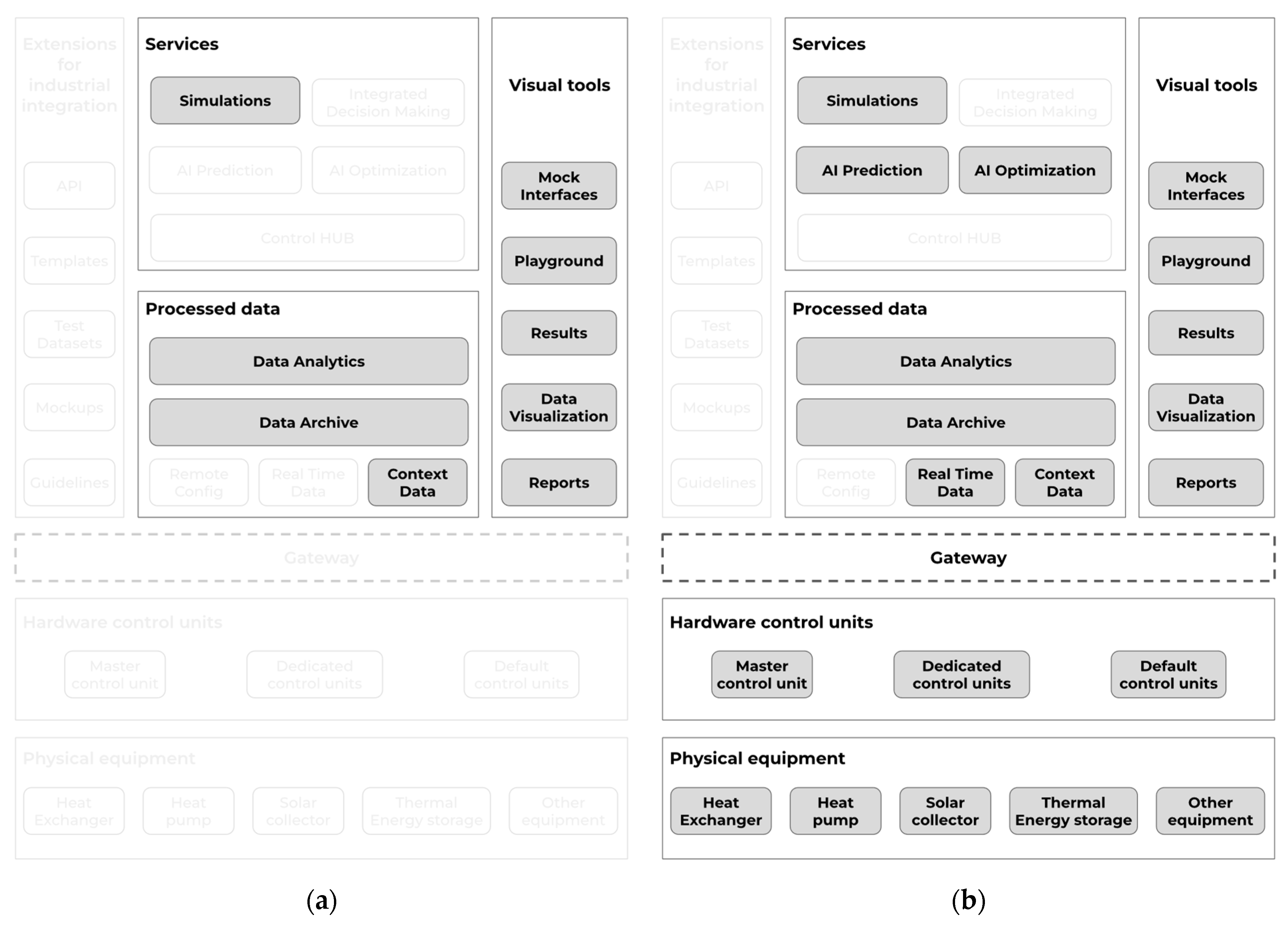
  • Default control units—these units represent and control physical equipment that already has an IoT compatible controller or there is an API available. Interfacing and controlling these devices will require low effort and financial costs due to their digital readiness.
  • Dedicated control units—we expect that some of the physical equipment have a closed-source controller, or a controller without communication capabilities. This type of device requires the augmentation of the specific physical unit with a dedicated controller. Usually, this is the case when the physical equipment is old, and replacing it with a new one that has IoT capabilities is not economically feasible. This is usually costly in terms of time and effort, as it requires domain knowledge about the device and additional sensors and computing hardware to acquire the device state.
  • Master controller unit—while the previous two types of control units are responsible for single physical devices, this control unit is responsible for reactive, time-critical operations, supervision, and orchestration of the system in case connection to higher control levels is not available temporarily due to a disruption in the network.
The Gateway layer realizes the bidirectional connection of the DT, bridging lower-level edge devices with higher-level software layers, which are deployed to a private or public cloud based on application requirements. In complex IoT systems, devices and controllers use diverse protocols, such as HTTP, MQTT, OPC-UA, or Modbus. The Gateway interfaces diverse systems providing a unified communication and easy integration of both legacy or proprietary devices and modern devices. The Gateway is also a central point where connected devices are maintained through a device management interface. This allows for device discovery, enrollment, and provisioning. Real-time monitoring such as device status and health checking procedures are also present. In addition to protocol translation and device management, the Gateway adds security features such as encryption, authentication, access control, or traffic filtering to protect the handled communication and data. Since the physical layer devices send data using multiple protocols and data formats, the Gateway also carries out preprocessing operations before sending the data to the upper layers with the purpose of data normalization and bandwidth usage optimization. These operations include the filtering of redundant data, the standardization of formats and measurement units across devices, or data compression. Instead of sending all preprocessed data to the cloud layers, the Gateway can also employ aggregation techniques such as time-based or event-based aggregation and batch transmission to further reduce the bandwidth and frequency of communication. The system chooses between the two aggregation techniques based on the nature of the data and analysis goal: while time-based aggregation is ideal where consistent time intervals are essential (e.g., time series forecasting, trends, and seasonality), event-based aggregation is used when data needs to be grouped around specific occurrences and events (e.g., process analysis, triggered alerts).
The next layer is the Processed Data Layer. This layer processes real-time data from the physical devices through the Gateway. Its main responsibility is to archive and analyze this data. The Processed Data Layer has the following modules:
  • Remote config—this module is responsible for translating high-level commands, configuration parameters, and goals received from the Service layer into coordinated sequences of machine-understandable commands for the physical layer devices that are delivered through the Gateway layer.
  • Real-Time data—this is a high throughput input module that ingests and processes the real-time data generated by the physical layer devices.
  • Context data—represents the specific global parameters of the physical devices together with relations between them. Contextual data consists of information such as geospatial data, physical characteristics, physical relationship to other objects, or environmental conditions. Contextual data is usually represented as knowledge graphs and ontologies.
  • Data Archive—represents a module with database-like responsibilities that saves historical data for retrieval and further analysis at a later date.
  • Data Analysis—this is a complex module enabled by statistical data analysis methods, including simpler machine learning and AI algorithms.
The Services layer consists of high-level applications and services:
  • Simulation—this module will perform different types of simulations of different physical assets, either individually or in combination with several assets. It is used together with the AI modules to provide results in what if analysis by doing performance simulation, stress testing simulation, control system simulation, or thermal and fluid dynamics simulation.
  • AI Prediction and AI Optimization—these two modules will mainly operate with archived data, contextual data, and simulation data to anticipate what will happen in the near or far future. As manual fine-tuning of a complex system is not feasible in a reasonable time, this will be done automatically with the help of Simulation and AI Optimization modules that will find the best parameter value for the system.
  • Integrated decision-making—using machine learning algorithms and advanced optimization techniques, this module evaluates potential courses of action under various scenarios and constraints, presenting decision-makers with prioritized options and recommended strategies. This functionality is particularly valuable in time-sensitive or high-stakes environments, where rapid and accurate decision-making is essential to maintaining continuity and achieving operational goals.
  • Control HUB—this module enables all the necessary Application Programming Interface (API) instances to connect to the system control. Its main role is to manage and coordinate data flow and control signals between the Service layer, and the underlying Processed Data and Gateway layers, translating them into actionable commands for the physical devices or intermediate control units.
The previous detailed layers are accompanied by a suite of Visual Tools and User Interaction modules, designed to facilitate the interaction between human operators and the complex digital systems they monitor and control. This interactive layer serves as a bridge between the high-level analytical capabilities of the digital twin and the expertise of engineers, operators, and other stakeholders by providing them with the following capabilities:
  • A simulation Playground where users can simulate various scenarios and explore the behavior of the twinned system under different conditions. Having an interactive risk-free environment, operators can experiment several “what-if” scenarios, exploring the effects of the parameter changes.
  • Data Visualization, Results, and Reports represent the main user interface for real-time monitoring and historical data review. Through dynamic graphs, charts, and heatmaps, the dashboard presents complex datasets in an intuitive format, enabling operators to monitor the system.
  • Mock Interfaces are included within the user interaction modules to provide a testing environment for connectivity and functionality. These interfaces simulate connectivity to different control units and devices within the digital twin system, allowing operators to test system behavior and diagnose potential connectivity issues without engaging the actual hardware.
The Extensions for Industrial Integration layer within the digital twin architecture, designed to facilitate cross-industry adaptability and interoperability. By incorporating API modules, reusable Templates, Test Datasets, and comprehensive documentation, this layer provides the tools necessary for deploying and configuring the digital twin across various industrial environments. It enables the digital twin to be quickly adapted to new contexts while maintaining compliance with industry standards, ultimately enhancing its scalability, efficiency, and industrial relevance. Through this extension, the digital twin system becomes a powerful, flexible solution that can respond to the evolving demands of multiple industrial domains, thereby supporting a wide range of applications in Industry 4.0 contexts. This layer addresses a gap in digital twin research and application, which often faces challenges in applicability across diverse industrial domains. By enabling a modular, template-driven approach to digital twin adaptation, this extension contributes to the development of a more universally applicable digital twin architecture.

3.1. Digital Twin Process Modeling Perspective

The twinning process, represented in Figure 2, involves a continuous bidirectional connection between physical and the corresponding virtual counterpart. While the physical to virtual connection creates and maintains a digital replica by observing and getting data from the physical world using the physical devices sensors, the virtual to physical provides optimized configuration and goal-oriented commands.
Using the terminology described in [38], the physical environment represents the measurable ‘real-world’ environment, within which the physical entity exists that influences its processes, state, or functionality. A physical entity refers to any man-made, tangible object that is twinned being defined by its properties, parameters, and physical characteristics. For example, while TES might not be heavily influenced by external temperature due to insulation, a renewable energy collection system such as solar panels or wind turbines will be directly influenced by external ambient factors. The virtual entity represents the virtually modelled physical entity that is used by virtual processes for analysis, simulation, and optimization. The results of these virtual processes are then sent back across the virtual to physical connection in the form of updates to the physical entity, modifying operational parameters or control strategies.
An important challenging characteristic of digital twins is their fidelity to the real world [38]. Fidelity determines the complexity of the virtual counterpart in terms of modeled parts and sub-parts, parameters, precision, abstraction level, or simulation details. Choosing the proper fidelity level for a specific physical entity requires having well-defined use cases and requirements for the digital twin. Requirements and use cases that define the fidelity level include data quality and resolution of the measurements, physical entity modeling complexity, digital twin simulation capabilities. Integration with external systems parameters such as socio-economic indexes or environmental data will increase the digital twin complexity but also improve the predictive capabilities and realism. According to multiple studies [38,39], very high-fidelity digital twin implementations are yet to be realized if not impractical to do, due to computational power limitations or development costs.

3.2. Tech Stack and Implementation Considerations

To instantiate the digital twin architecture, a comprehensive set of technologies is required, each playing a critical role in the process of data acquisition, simulation, 3D rendering, and deployment across cloud and edge infrastructure.
At the Hardware Control layer, low-level data acquisition and transmission to the Gateway layer are achieved through technologies such as OPC-UA, or MQTT, for example. OPC-UA represents a standardized means of facilitating secure and reliable data exchange between industrial machines, IoT devices, and sensors, making it particularly suited for manufacturing or energy management systems. Compared to OPC-UA, MQTT is a lightweight messaging protocol that enables IoT devices operating in low-bandwidth environments to efficiently transmit data to servers and receive commands and configuration parameters.
The Gateway layer requires SCADA capabilities, coupled with a temporary storage to be able to do all the data preprocessing described above. Since the data is received in real-time, a time series database such as InfluxDB (v.2.7.10) or Prometheus (v3.0.1) can be used. As this data will not be available for long periods, an in-memory database such as Redis (v.7.4.2) is also viable. For protocol translation, solutions such as Eclipse Hono (v.2.4.1) can be used, where multiple protocol adapters are implemented, simplifying the process of connecting multiple devices that use different communication protocols.
Again, in the Processed Data layer, InfluxDB or Prometheus can be used for persistent storage. The Data Analysis, AI Optimization, and AI Prediction will contain custom build or off-the-shelf AI and ML models. Considering the AI industry boom, there are many potential frameworks and services through which these architectural modules can be instantiated. While for prototyping, testing, and developing AI and ML models, Tensorflow or Pytorch are some of the most popular frameworks, deploying and training these models at large with real-time data requires complex operation, usually achieved using services offered by large cloud providers such as Amazon Web Services (AWS), Google Cloud, or Microsoft Azure.
The Simulation module plays an important role in linking the physical system’s real-time data with virtual models. As each use case has different simulation requirements, an FMI (Functional Mock-up Interface) standard compatible simulator is required. The FMI standard allows for the integration of different simulation tools, allowing them to exchange data and work together, providing a cohesive virtual model of a physical system.
Data Visualization, Reports, and user interfaces can be easily configured using tools like Grafana, where the Playground can be developed using 3D game engines such as Unity or Unreal Engine.
Deploying these components in the cloud is done using technologies such as Docker for modules or layer containerization, while Kubernetes is used for running and orchestrating these containers in the cloud.
To conclude this section, to create a digital twin that operates efficiently, reliably, and at scale, multiple technologies are required to be interfaced, increasing the development complexity of such systems. Table 2 summarizes the main digital twin implementation requirements and provide examples of potential solutions that satisfy each of them.

4. High-Temperature Heat Upgrade Use Case

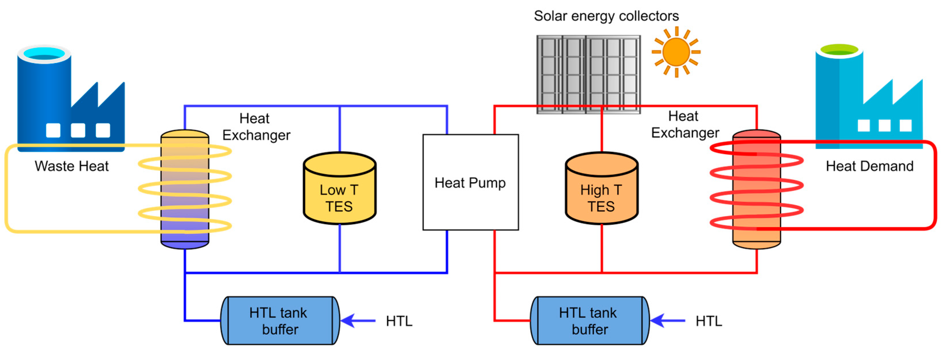
4.1. Physical System Perspective

The physical system of the digital twin is represented by the high-temperature heat upgrade system prototype developed as part of the ongoing SUSHEAT project [9,10]. This innovative system will collect renewable energy, combined with the waste energy to be stored so it can be used at a later time in energy-intensive industrial processes. These types of systems are complex in nature and require process optimization and orchestration due to the high level of interdependencies between system components and parameters. A simple concept of such high high-temperature heat upgrade system is detailed in Figure 3, and it has the following components:
  • Waste heat—represents a low-temperature energy source. SUSHEAT targets industrial processes that generate residual heat that is usually lost in the environment.
  • Low and High T Thermal Energy Storage—these are two Thermal Energy Storage (TES) devices for the two loops of the system: the cold loop and the hot loop. Useful in situations where there is no high heat demand and the waste energy can be stored in TESes, or when there is no waste heat available, the energy can be extracted from TESes. Two approaches are currently used to find a suitable TES design for the SUSHEAT prototype. One direction explores the use of biomimicry inspiration optimized by genetic algorithms [40] and built using additive manufacturing [41], while the other direction is to use a U-net CNN-based network [42]. The Low T TES is designed for 15 kWh, while the High T TES is aimed for 30 kWh.
  • Heat exchangers—two heat exchangers, one for capturing the waste heat into the system, and one to transfer the high-temperature heat to the heat demand process.
  • Heat pump—a custom-made heat pump that can output high temperature. Currently, a prototype of a Stirling-cycle heat pump designed for normal operation at 200 kWh with a maximum heat capacity of 400 kW is being tested in a biogas facility, and is able to provide heat up to 200 °C using a source as low as 10 °C with high efficiency, having a COP of up to 3 [43,44]. The SUSHEAT heat pump prototype aims at temperatures up to 250 °C to meet the demands of multiple industries.
  • HTL tank buffers—two heat transfer liquid (HTL) buffers, one for each system loop. They are necessary for system safety and pressure damping, ensuring full system flexibility with different types of HTLs across different temperature ranges.
  • Solar energy collectors—provide additional energy into the system. Depending on the heat demand, medium or high-temperature collectors can be used. In our case, Fresnel collectors, a type of high-temperature collector, will be used.
  • Heat demand—this represents an industrial process that requires a high temperature to operate, usually between 150 °C and 250 °C, considering the current heat pump capabilities and market needs [11].
Figure 3. The concept of a high-temperature heat upgrade system (adapted from [9,45]).
Applsci 15 02350 g003
To be able to test the SUSHEAT concept, we will use a simplified system, a laboratory rig, where we simulate the waste heat and Fresnel collectors using electric heaters, and the heat demand with a heat sink. The testing framework uses water as HTL. More details regarding the engineering considerations and preliminary design of the SUSHEAT laboratory rig can be found in [46].

4.2. Mathematical Modeling

To be able to simulate the concept described in the previous section, we modeled the system as shown in Figure 4. The waste energy source from the cold loop and the solar collectors from the hot loop are represented by electric heaters, while the energy demand is considered to be a heat sink element. To control the flow of HTL, the model contains electric valves coupled with pressure, temperature, and flow sensors. To ensure the safety of the system, we added pressure safety valves and pressure vessels.
The heat pump transfers the energy from the cold loop ( Q C L ) to the hot loop ( Q H L ) using electrical power ( W e ). Each loop’s energy is dependent on the mass flow rate of the HTL ( ), the specific heat capacity of the HTL ( C p , H T F ), and the temperature difference between the inlet and outlet ( Δ T = T o u t T i n ). With these variables defined in Equations (1)–(3), we can define the coefficient of performance ( C O P ) of the heat pump as in Equation (4).
Q C L = C L   C p , H T F   Δ T C L
Q H L = H L C p , H T F Δ T H L
Q H L = Q C L + W e
C O P = Q H L W e
The thermal energy storage elements undergo charge and discharge cycles depending on the heat pump output and the energy demand. Similarly to the heat pump, TES energy can be computed using Equation (5). A more insightful characteristic would be the mean power of the TES ( Q ¯ T E S ) during an entire cycle, defined by Equation (6) [41], where Δ T T E S is the temperature difference between the inlet and outlet, Δ t is the time interval between two readings, and t is the time taken by the PCM to vary from the initial T P C M , i temperature to the final T P C M , f temperature.
Q T E S =   C p , H T F   Δ T T E S
Q ¯ T E S = T P C M , i T P C M , f   C p Δ T T E S Δ t t
For the electric heaters of the cold and hot loops and the heat exchanger, we use Equation (7).
Q E H =   C p , H T F   Δ T E H
For the pressure measuring and pressure vessel simulation, we use Equation (8), where α H T F represents the volumetric coefficient of thermal expansion for HTF and α v for the vessel, Δ T is the temperature change, β is the relative change in volume of HTF per unit pressure, with D ,   L and E being the diameter, thickness and elastic modulus of the pressure vessel, respectively.
Δ P = ( α H T F α v )   Δ T / ( β + D L   E )
To conclude the system modeling, we list all the important input/output simulation variables with their measurement unit in Table 3, grouped by system component.

4.3. System Simulation

The high-temperature heat upgrade system is simulated using TwinCAT XAE (v.3.1), which has the advantage of being integrated with a modern IDE such as Visual Studio. This integration offers improved debugging, real-time system control, and streamlined code development. In addition to simulating each individual component using the previously listed equations from Section 4.2, the simulation also contains the entire system control logic. A human-machine interface (HMI) was developed using both Ladder Diagram (LD) and Structured Text (ST) PLC programming languages, enabling comprehensive control and flexibility. The HMI contains a control panel that displays the system layout together with sensor data and parameter values as in Figure 5. The interface is animated, showing HTL flows or valves state. For more information, each system component from the control panel can be interacted with to pop up a detailed view, as shown in Figure 6. System values and target parameters are displayed in the simulated values pop-up (Figure 6). These parameters can be adjusted at the beginning of the simulation to test different operational conditions.

4.4. 3D Modeling of the System

To better understand and visualize the high-temperature heat upgrade system, a 3D application was developed. This model replicates the layout of a prototype testing rig used in developing the final heat upgrade system, allowing users to interact with and better comprehend the system’s complex structure and processes. Unity (v.6) was selected to develop this application due to its versatility, cross-platform support, and integration with other popular development tools. This is an important aspect as it opens multiple user interaction methods and devices, specific to different types of users.
The current application allows the user to navigate freely through a simulated environment where the high-temperature heat upgrade system is placed. Along the pipes, animated arrows are color-coded to indicate the temperature of the heat transfer fluid, with red representing high temperatures and blue indicating cooler temperatures. These arrows also display the flow direction of the fluid. System components, such as TES, heat pump, or Fresnel collectors, can be interacted with to visualize specific parameters. Another area of interest is represented by a dashboard, where general system parameters can be visualized. A screenshot of the 3D model can be seen in Figure 7.

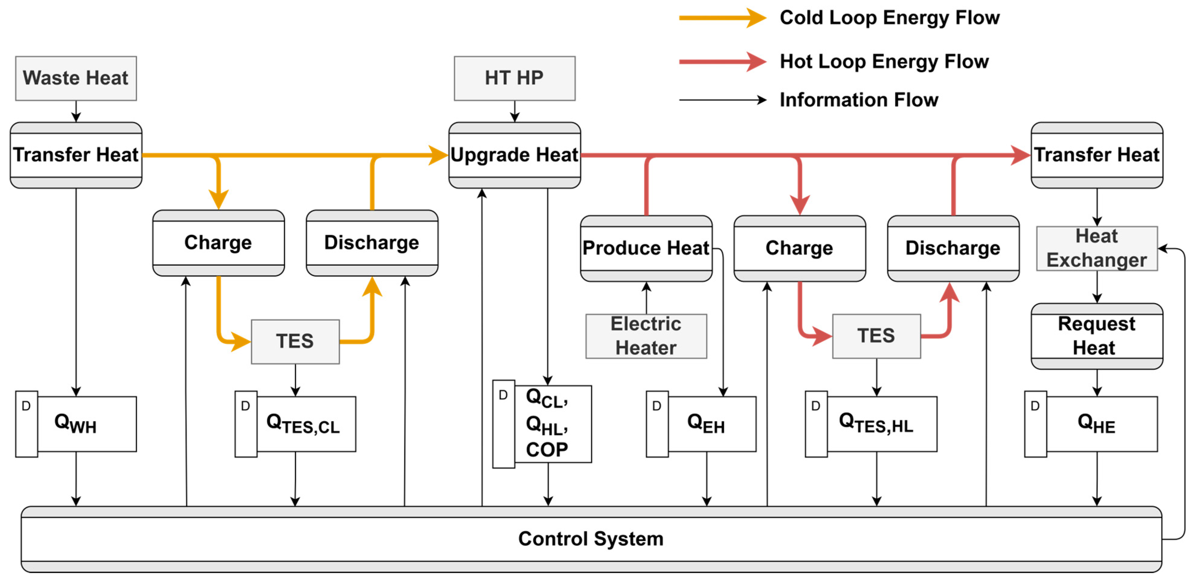
4.5. Data Flow and Process Modeling

The concept presented above is completed with a control system that integrates all the components and decides which and how much energy from every resource is used to charge the two thermal storage systems, according to their availability, energy requirements, and constraints of specific industries.
The diagram in Figure 8 presents the information flow between system entities, processes, and data stores for a possible arrangement of the high-temperature heat upgrade system. The diagram represents system entities using rectangles (Waste Heat, HT-HP, TES, Electric Heater, and Heat Exchanger) while processes are defined with rounded rectangles (Transfer Heat, Charge, Discharge, Produce Heat, Request Heat). The most important input and output parameters that are transferred in the system are represented by data store elements ( Q W H ,   Q T E S , C L ,   Q T E S , H L ,   Q C L ,   Q H L ,   C O P ,   Q E H ,   Q H E ) and connected to the process by information flow arrows. For a better understanding of the information flow, we also display the energy flow generated by the physical processes using the color-coded arrows, yellow for the cold loop and red for the hot loop.
The external industrial process, denoted as Waste Heat in the diagram, Transfers Heat into our system and generates a production of energy curve that is saved into the datastore as Q W H . The same is true for the Fresnel collectors, represented by the Electric Heater. The Heat Exchanger is also an external industrial process that can request high-temperature heat at any moment, based on the demand curve, Q H E . As these entities and processes are dependent on environmental data that we cannot control, we can only collect data from them.
The TESes from both hot and cold loops can Charge and Discharge with energy. We consider them as passive entities equipped with sensors that can measure the stored energy at a given moment. The TES sensor readings are saved in Q T E S , C L and Q T E S , H L datastores.
The Upgrade Heat process, controlled by the HT-HP, uses low thermal energy as input from either industrial heat or from a TES and outputs high thermal energy that can be used directly in the Transfer Heat process of the Heat Exchanger or can be stored in a TES through its Charge process.
The Control System acts as an orchestrator for the system’s processes. Based on the current heat demand, and the other entities’ information, it ensured the thermal energy equilibrium in the system. It controls when the surplus thermal energy is stored in a TES through a Charge process and when to supply this energy through the Discharge process. It also configures the Upgrade Heat process of the HT-HP by providing information about the demand. Based on past data and sensor readings, the Control System creates forecasts of the different energy inputs and measurements of the system so it can provide relevant information to the high heat demand regarding its energy request.

5. Discussion

5.1. Digital Twin Iteration Process

Developing a digital twin in parallel with the create and build cycles of the physical system raises additional challenges, particularly due to the absence of a bidirectional connection with the physical system during early stages, since data is the driving element of the DT [47]. To classify different degrees of data integration and automation level of the bidirectional communication, authors of [48] introduce three types of DT, from simplest to most complex one: digital model, digital shadow, and digital twin. These three DT levels can be used as key steps in an iterative development process of DT. This process is close to what the DT throughout the product lifecycle was envision in [49] where only two types of DT are used: DT prototype and DT instance. Similarly, from a DT-based product design perspective, this process consists of conceptual design, detailed design and virtual verification [13].
The first step is represented by creating a digital model of the desired physical system, including mathematical modelling, 3D environmental representation, and computer-aided design (CAD). The digital model is used in simulations allowing for virtual analysis of the physical system potential. At the same time, it supports evaluation of control systems and workflow designs, providing valuable insights during the initial phases. For our DT architecture, to instantiate a digital model would mean creating the Simulation component of Services layer, coupled with the Visual Tools layer and most of the components of Processed data layer, as seen in Figure 9a.
During the build phase of the physical model, the physical-to-virtual connection becomes operational, allowing real-world data to be collected and integrated into the digital model. This synchronization enables real-time monitoring and analysis of the physical system, allowing the refinement of AI algorithms and updates to the digital model for increased accuracy. In addition to the architectural components of a digital model, Physical and Hardware Control Units layers are now available. Instantiating the Real Time Data component from Processed Data layer, AI Prediction and Optimization services completes this step, transforming the digital model into a digital shadow. The required digital shadow components can be seen in Figure 9b.
The final stage Is achieved when the virtual-to-physical connection is established, completing the real-time bidirectional link though the Control HUB and Remote Config modules. This feedback loop connection upgrades the digital shadow to a fully functional digital twin, enabling it to interact with and directly control the physical system. The real-time feedback loop ensures continuous optimization and operational alignment between the digital and physical counterparts as described in Section 3. All the DT components can be seen in Figure 1.

5.2. Digital Twin Architectural Modularity

System modularity is a design principle that involves decomposing a complex system into smaller, functionally independent modules [50]. This results in two main benefits [51]: the creation of flexible options for designers and users, and the capacity for evolutionary development, allowing for the iterative testing, selection, and integration of improved modules over time.
The proposed digital twin architecture demonstrates modularity by explicitly dividing the system into distinct, loosely coupled layers, each addressing a specific set of functionalities, aligning with the core principles of modular design. This separation of concerns facilitates flexibility, maintainability, and scalability, as changes to one module can be made with minimal impact on the rest of the system.
At the base layer, the DT architecture isolates physical equipment and control units from higher-level processing and service functions. The Physical Equipment layer contains all tangible assets, while the Hardware Control Units layer manages device-specific control with varying levels of digital readiness. This clear separation ensures that any evolution or replacement in physical devices or their immediate control mechanisms does not necessitate extensive changes in the upper layers. The Gateway layer main role is standardizing the communication across different protocols, ensuring interoperability between legacy systems and modern IoT devices, decoupling the heterogenous physical system from the digital process from the above layers.
The upper digital layers, Processed Data, Services, and Visual Tools are subdivided into specialized modules that allows to independently process and manage data or to easily adopt different services and user interfaces according to the specific application needs. The Extensions for Industrial Integration layer further underlines the modular approach by offering components that facilitates the adoption of the proposed solution across diverse scenarios.

5.3. Digital Twin Benefits

As seen in the literature [52], most digital twin development starts after having a physical entity. This is not always the case, as digital twins can also exist during the creation phase of a product life cycle [49], which includes four main phases: create, build, operate, and dispose. Developing a digital twin early in the creation phase offers key advantages, such as enabling virtual testing, identifying design inefficiencies, and accelerating development by simulating components before they are physically available.
Our digital twin use case of high-temperature heat upgrade systems for industrial processes currently covers both the create and build lifecycles. While the physical system is still under development [46], with only some of the components available as physical prototypes (TES [40,41,42] and HT-HP [43,44,45]), and the other components are physically simulated (electric heaters and heat sinks for the waste heat and heat demand respectively), the digital twin development can continue unrestricted. As the physical and the digital counterpart are not tightly coupled, modeling and simulating components do not require to have the physical entity present. This allows for greater flexibility in terms of development approaches. By having flexible twin prototypes for each component of the heat upgrade system, the digital twin can optimize the design by taking into account environmental data, waste heat availability, and heat demand throughout a large period of time. This process provides system design parameters, such as the optimal TES PCM, TES volume, HT-HP power consumption, and whether additional green energy sources such as Fresnel collectors should be included. By building the digital system before the physical counterpart, we can easily create different settings for each desirable physical implementation of the high-temperature heat upgrade system, regardless of the industries involved or geographical environment characteristics.
An advantage of this approach is integrating physical devices with virtual simulated devices. This enables continuous testing during the build phase, finding errors faster. While usually prototypes are tested in stand-alone settings, with the help of digital twins the entire heat upgrade system can be tested as a whole. This approach, of model and simulation first, also improves costs by not having to physically build every iteration of the prototype.
Once the digital twin is linked to the physical counterpart, the benefits are realized through the Service layer of the proposed digital twin architecture. Using the already available historical and real-time data, the digital twin system provides a real-time, virtual representation of the entire waste heat recovery system. With the help of visual interfaces, operators can monitor key parameters such as waste heat availability, heat pump performance, heat delivery efficiency, and system temperatures, and quickly identify any deviations from expected performance.
By simulating the thermal dynamics of the system, the digital twin can optimize the capture and upgrading of waste heat based on real-world data. The system can continuously adjust parameters such as pressure and flow rates to maximize the efficiency of the heat pump. This optimization reduces energy losses, ensures maximum recovery of waste heat, and enhances the overall system’s energy efficiency. Operators can simulate various “what-if” scenarios to explore different operational strategies and process improvements. For instance, operators can test the impact of adjusting heat pump settings, varying heat load demands, or implementing different control algorithms without interrupting the real-world operation. This provides valuable insights into how the system would perform under different conditions, leading to continuous process improvement and innovation.
Using the AI predictive capabilities, the digital twin system will forecast equipment wear and potential failures. Sensors in the physical system feed data into the virtual twin, allowing the system to predict when components such as heat exchangers, compressors, or pumps might require maintenance. By predicting maintenance needs in advance, the system can avoid unplanned downtime and extend the lifespan of critical components.

5.4. Research Gaps

While the research presented in this paper demonstrates the potential and benefits of a digital twin architecture for high-temperature heat upgrade systems, we also identified some drawbacks that constrain its generalizability and applicability. These current gaps also provide directions for future work.
The current paper research primarily focuses on the SUSHEAT high-temperature heat upgrade system. While this specific application provides valuable insights, the findings may not directly translate to other types of industrial systems or different temperature ranges.
The proposed digital twin architecture leverages a specific set of technologies for implementation, including mathematical modeling, 3D visualization, and control systems. This reliance on certain software tools and platforms may limit the adaptability of the architecture to other contexts where alternative technologies are used.
Although the digital twin was utilized during the design and building of the SUSHEAT system, the validation process is confined to the simulation and integration testing phases. Long-term operational performance under real-world industrial conditions was not assessed, requiring further research regarding the system’s reliability and efficiency over time.

6. Industrial Renewable Energy Upgrade System Cases

While the presented digital twin use case presented in Section 4 of this article is linked to a laboratory physical test rig, the SUSHEAT project aims at experimenting the entire concept (including the presented digital twin) in two industry use cases: fish oil with Pelagia [53], and dairy processing with Mandrekas [54]. As the physical system to be installed in both industries will remain almost identical, the differentiation lies in the parameter configurations and control strategies, which are tailored based on simulations conducted using the digital twin. This adaptability ensures that the system can meet the specific operational requirements of each industrial setting, highlighting the flexibility and adaptability of this system. The digital twin plays an important role in this customization process, allowing for precise adjustments to the system’s operation through simulated testing. These simulations help optimize parameters such as heat flow rates, temperature targets, and energy storage schedules, ensuring that each implementation achieves maximum efficiency and performance. After finishing the building of the physical laboratory test rig (est. 2027), we aim to look further into the following: expansion to other industrial use-cases, long-term monitoring and performance assessments to gain deeper insights into the scalability and robustness of the architecture and cost-benefit analysis. Below, in the following sub-sections, we added specific application details regarding the current focus regarding the two primary industry use cases.

6.1. Fish Oil Industry

Pelagia’s facilities produce ingredients primarily for the aquaculture industry, relying on fossil-fueled steam boilers to generate steam starting at 175 °C for cooking and drying processes. Final product drying requires even higher temperatures, ranging from 200 °C to 250 °C. The current system’s dependence on fossil fuels contributes significantly to greenhouse gas emissions and operational costs. Additionally, waste heat is available from two key sources: humid air dryers and condensate streams, presenting both an opportunity and a technical challenge for recovery and reuse. An important aspect of this use case is that Pelagia’s plants operate in Norway, where the challenging northern latitude climate limits the use of solar energy.
For Pelagia use-case the system will be optimized to target the following:
  • Increased energy efficiency compared to traditional steam boilers.
  • Environmental sustainability by decreasing the greenhouse gas emissions.
  • Cost savings by reducing the carbon dioxide quota.
  • Process optimization as the transition from steam boilers to heat pumps will necessitate a more proactive approach to equipment operation and maintenance.

6.2. Dairy Production Industry

The integration of SUSHEAT technologies at Mandrekas dairy production facilities in Corinth, Greece, aims to enhance sustainability and operational efficiency by incorporating a high-temperature heat pump and solar energy to complement the existing LPG-fueled steam boilers. This existing system is designed to support steam generation at 175 °C, addressing diverse heating needs for milk pasteurization, homogenization, and mixing processes, while also facilitating efficient cooling cycles. By reducing dependency on fossil fuels and leveraging renewable energy sources, Mandrekas anticipates significant progress toward its sustainability goals, strengthening its environmental reputation and securing a competitive advantage within the dairy industry.
For Mandrekas use-case the system will be optimized to target the following:
  • Precise estimations of head-demand and heat production to allow more flexibility for the production planning, worker shifts, and product diversification.
  • Parametrization of the system based on different manufacturing processes and products.
  • Faster studies and research for new products.

7. Conclusions

The presented concept builds on the state-of-the-art research in digital twin architectures by addressing the specific challenges of high-temperature heat upgrade systems. Like the analyzed frameworks such as Grieves’ foundational model, the 5D-DT architecture, GDTA, or OpenTwins, our approach incorporates key elements such as modularity, scalability, and robust data handling, emphasizing a layered approach, ensuring that each functional aspect is addressed systematically.
The current paper presents a digital twin architecture for a high-temperature heat upgrade system. Having six logical layers, the architecture covers the main requirements of a digital twin platform and covers the specific needs of heat upgrade systems. We instantiated this architecture and presented its usefulness during the creation and building of the physical system. To achieve this, we modeled the system mathematically, simulated the control system, and created a 3D visualization. Additionally, the twinning process specific to the digital twin and the data flow specific to the high-temperature heat upgrade system are presented. Using the digital twin during the physical system creation and building provided us with meaningful insights during system simulation and physical components integration testing.
In summary, our architecture not only advances digital twin research for industrial energy systems but also provides a flexible and scalable blueprint for similar applications. By integrating innovative energy systems with a focus on human-in-the-loop approaches, the proposed framework aligns with global decarbonization efforts and supports the objectives of the European Green Deal [1], showing the potential of digital twin technology to support sustainable and efficient industrial processes.

Author Contributions

Conceptualization, A.M., A.B., C.-B.Z. and J.D.M.; methodology, A.M. and A.B.; software, A.M. and A.B.; validation, A.M., A.B., C.-B.Z. and J.D.M.; formal analysis, A.M., A.B., C.-B.Z. and J.D.M.; investigation, A.M. and A.B.; resources, A.B. and C.-B.Z.; data curation, A.M. and A.B.; writing—original draft preparation, A.M.; writing—review and editing, A.M., A.B., C.-B.Z. and J.D.M.; visualization, A.M. and A.B.; supervision, A.B. and C.-B.Z.; project administration, A.B. and C.-B.Z.; funding acquisition, A.B. and C.-B.Z. All authors have read and agreed to the published version of the manuscript.

Funding

This material has received funding by the European Union—Grant Agreement No 101103552—SUSHEAT—Smart Integration of Waste and Renewable Energy for Sustainable Heat Upgrade in the Industry. Views and opinions expressed are however those of the author(s) only and do not necessarily reflect those of the European Union or CINEA. Neither the European Union nor the granting authority can be held responsible for them. This work was supported by the Hasso Plattner Excellence Research Grant LBUS-HPI-ERG-2020-03, financed by the Knowledge Transfer Center of the Lucian Blaga University of Sibiu.

Institutional Review Board Statement

Not applicable.

Informed Consent Statement

Not applicable.

Data Availability Statement

The original contributions presented in this study are included in the article. Further inquiries can be directed to the corresponding author.

Conflicts of Interest

Authors Alexandru Matei and Alex Butean were employed by the company Wiz Development and Services. The remaining authors declare that the research was conducted in the absence of any commercial or financial relationships that could be construed as a potential conflict of interest.

References

  1. The European Green Deal—European Commission. Available online: https://commission.europa.eu/strategy-and-policy/priorities-2019-2024/european-green-deal_en (accessed on 30 December 2024).
  2. Deng, X.; Lv, T. Power System Planning with Increasing Variable Renewable Energy: A Review of Optimization Models. J. Clean. Prod. 2020, 246, 118962. [Google Scholar] [CrossRef]
  3. Thirunavukkarasu, M.; Sawle, Y.; Lala, H. A Comprehensive Review on Optimization of Hybrid Renewable Energy Systems Using Various Optimization Techniques. Renew. Sustain. Energy Rev. 2023, 176, 113192. [Google Scholar] [CrossRef]
  4. Fan, Z.; Yan, Z.; Wen, S. Deep Learning and Artificial Intelligence in Sustainability: A Review of SDGs, Renewable Energy, and Environmental Health. Sustainability 2023, 15, 13493. [Google Scholar] [CrossRef]
  5. Pandey, V.; Sircar, A.; Bist, N.; Solanki, K.; Yadav, K. Accelerating the Renewable Energy Sector through Industry 4.0: Optimization Opportunities in the Digital Revolution. Int. J. Innov. Stud. 2023, 7, 171–188. [Google Scholar] [CrossRef]
  6. Talari, S.; Shafie-khah, M.; Osório, G.J.; Aghaei, J.; Catalão, J.P.S. Stochastic Modelling of Renewable Energy Sources from Operators’ Point-of-View: A Survey. Renew. Sustain. Energy Rev. 2018, 81, 1953–1965. [Google Scholar] [CrossRef]
  7. Ould Amrouche, S.; Rekioua, D.; Rekioua, T.; Bacha, S. Overview of Energy Storage in Renewable Energy Systems. Int. J. Hydrogen Energy 2016, 41, 20914–20927. [Google Scholar] [CrossRef]
  8. Ammari, C.; Belatrache, D.; Touhami, B.; Makhloufi, S. Sizing, Optimization, Control and Energy Management of Hybrid Renewable Energy System—A Review. Energy Built Environ. 2022, 3, 399–411. [Google Scholar] [CrossRef]
  9. Rovira, A.; Guedez, R.; Trevisan, S.; Høeg, A.; Vérez, D.; Cabeza, L.F.; Butean, A.; Enríquez, J.; Law, R.; Muegge, M.; et al. Smart Integration of Waste and Renewable Energy for Sustainable Heat Upgrade in the Industry (SUSHEAT). 2023. Available online: https://zenodo.org/records/8367412 (accessed on 2 October 2024).
  10. Horizon EU SUSHEAT. Available online: https://susheat.eu/ (accessed on 10 November 2024).
  11. Marcos, J.D.; Golpour, I.; Barbero, R.; Rovira, A. Decarbonizing European Industry: A Novel Technology to Heat Supply Using Waste and Renewable Energy. Appl. Sci. 2024, 14, 8994. [Google Scholar] [CrossRef]
  12. Grieves, M.; Vickers, J. Digital Twin: Mitigating Unpredictable, Undesirable Emergent Behavior in Complex Systems. In Transdisciplinary Perspectives on Complex Systems; Kahlen, F.-J., Flumerfelt, S., Alves, A., Eds.; Springer International Publishing: Cham, Switzerland, 2017; pp. 85–113. ISBN 978-3-319-38754-3. [Google Scholar]
  13. Tao, F.; Cheng, J.; Qi, Q.; Zhang, M.; Zhang, H.; Sui, F. Digital Twin-Driven Product Design, Manufacturing and Service with Big Data. Int. J. Adv. Manuf. Technol. 2018, 94, 3563–3576. [Google Scholar] [CrossRef]
  14. Tao, F.; Zhang, M.; Nee, A.Y.C. Five-Dimension Digital Twin Modeling and Its Key Technologies. In Digital Twin Driven Smart Manufacturing; Elsevier: Amsterdam, The Netherlands, 2019; pp. 63–81. ISBN 978-0-12-817630-6. [Google Scholar]
  15. Lee, J.; Bagheri, B.; Kao, H.-A. A Cyber-Physical Systems Architecture for Industry 4.0-Based Manufacturing Systems. Manuf. Lett. 2015, 3, 18–23. [Google Scholar] [CrossRef]
  16. Steindl, G.; Stagl, M.; Kasper, L.; Kastner, W.; Hofmann, R. Generic Digital Twin Architecture for Industrial Energy Systems. Appl. Sci. 2020, 10, 8903. [Google Scholar] [CrossRef]
  17. Adolphs, P.; Bedenbender, H.; Dirzus, D.; Ehlich, M.; Epple, U.; Hankel, M.; Heidel, R.; Hoffmeister, M.; Huhle, H.; Kärcher, B.; et al. Reference Architecture Model Industrie 4.0 (Rami4.0). ZVEI and VDI, Status Report 2015. Available online: https://www.zvei.org/fileadmin/user_upload/Presse_und_Medien/Publikationen/2016/januar/GMA_Status_Report__Reference_Archtitecture_Model_Industrie_4.0__RAMI_4.0_/GMA-Status-Report-RAMI-40-July-2015.pdf (accessed on 5 November 2024).
  18. Kasper, L.; Birkelbach, F.; Schwarzmayr, P.; Steindl, G.; Ramsauer, D.; Hofmann, R. Toward a Practical Digital Twin Platform Tailored to the Requirements of Industrial Energy Systems. Appl. Sci. 2022, 12, 6981. [Google Scholar] [CrossRef]
  19. Robles, J.; Martín, C.; Díaz, M. OpenTwins: An Open-Source Framework for the Development of next-Gen Compositional Digital Twins. Comput. Ind. 2023, 152, 104007. [Google Scholar] [CrossRef]
  20. Functional Mock-Up Interface. Available online: https://fmi-standard.org/ (accessed on 28 November 2024).
  21. Infante, S.; Martín, C.; Robles, J.; Rubio, B.; Díaz, M.; Perea, R.G.; Montesinos, P.; Poyato, E.C. Integrating FMI and ML/AI Models on the Open-source Digital Twin Framework OpenTwins. Softw. Pract. Exp. 2024, 54, 1470–1490. [Google Scholar] [CrossRef]
  22. You, M.; Wang, Q.; Sun, H.; Castro, I.; Jiang, J. Digital Twins Based Day-Ahead Integrated Energy System Scheduling under Load and Renewable Energy Uncertainties. Appl. Energy 2022, 305, 117899. [Google Scholar] [CrossRef]
  23. Van Dinter, R.; Tekinerdogan, B.; Catal, C. Reference Architecture for Digital Twin-Based Predictive Maintenance Systems. Comput. Ind. Eng. 2023, 177, 109099. [Google Scholar] [CrossRef]
  24. Gourisetti, S.N.G.; Bhadra, S.; Sebastian-Cardenas, D.J.; Touhiduzzaman, M.; Ahmed, O. A Theoretical Open Architecture Framework and Technology Stack for Digital Twins in Energy Sector Applications. Energies 2023, 16, 4853. [Google Scholar] [CrossRef]
  25. Semeraro, C.; Olabi, A.G.; Aljaghoub, H.; Alami, A.H.; Al Radi, M.; Dassisti, M.; Abdelkareem, M.A. Digital Twin Application in Energy Storage: Trends and Challenges. J. Energy Storage 2023, 58, 106347. [Google Scholar] [CrossRef]
  26. Kasper, L.; Schwarzmayr, P.; Birkelbach, F.; Javernik, F.; Schwaiger, M.; Hofmann, R. A Digital Twin-Based Adaptive Optimization Approach Applied to Waste Heat Recovery in Green Steel Production: Development and Experimental Investigation. Appl. Energy 2024, 353, 122192. [Google Scholar] [CrossRef]
  27. Ontop. Available online: https://ontop-vkg.org/ (accessed on 28 November 2024).
  28. Guo, Y.; Tang, Q.; Darkwa, J.; Wang, H.; Su, W.; Tang, D.; Mu, J. Multi-Objective Integrated Optimization of Geothermal Heating System with Energy Storage Using Digital Twin Technology. Appl. Therm. Eng. 2024, 252, 123685. [Google Scholar] [CrossRef]
  29. Aguilera, J.J.; Meesenburg, W.; Markussen, W.B.; Zühlsdorf, B.; Elmegaard, B. Real-Time Monitoring and Optimization of a Large-Scale Heat Pump Prone to Fouling—Towards a Digital Twin Framework. Appl. Energy 2024, 365, 123274. [Google Scholar] [CrossRef]
  30. Aguilera, J.J.; Padullés, R.; Meesenburg, W.; Markussen, W.B.; Zühlsdorf, B.; Elmegaard, B. Operation Optimization in Large-Scale Heat Pump Systems: A Scheduling Framework Integrating Digital Twin Modelling, Demand Forecasting, and MILP. Appl. Energy 2024, 376, 124259. [Google Scholar] [CrossRef]
  31. Seifert, J.; Haupt, L.; Schinke, L.; Perschk, A.; Hackensellner, T.; Wiemann, S.; Knorr, M. Digital Twin for Heat Pump Systems: Description of a Holistic Approach Consisting of Numerical Models and System Platform. In Proceedings of the CLIMA2022 | The 14th REHVA HVAC World Congress, Rotterdam, The Netherlands, 22–25 May 2022; pp. 2201–2207. [Google Scholar] [CrossRef]
  32. Savage, T.; Akroyd, J.; Mosbach, S.; Hillman, M.; Sielker, F.; Kraft, M. Universal Digital Twin—The Impact of Heat Pumps on Social Inequality. Adv. Appl. Energy 2022, 5, 100079. [Google Scholar] [CrossRef]
  33. The World AvatarTM. Available online: https://theworldavatar.io/ (accessed on 28 November 2024).
  34. Lv, R.; Yuan, Z.; Lei, B. A High-Fidelity Digital Twin Predictive Modeling of Air-Source Heat Pump Using FCPM-SBLS Algorithm. J. Build. Eng. 2024, 87, 109082. [Google Scholar] [CrossRef]
  35. Tepsa, T.; Haavikko, M.; Li, O.; Ruismaki, V.-M.; Kangas, S.; Kattelus, J.; Vaataja, H. A Digital Twin of a Heat Pump with a Game Engine for Educational Use. In Proceedings of the 2022 45th Jubilee International Convention on Information, Communication and Electronic Technology (MIPRO), Opatija, Croatia, 23 May 2022; IEEE: Piscataway, NJ, USA, 2022; pp. 1341–1346. [Google Scholar]
  36. Khan, T.; Yu, M.; Waseem, M. Review on Recent Optimization Strategies for Hybrid Renewable Energy System with Hydrogen Technologies: State of the Art, Trends and Future Directions. Int. J. Hydrogen Energy 2022, 47, 25155–25201. [Google Scholar] [CrossRef]
  37. He, P.; Almasifar, N.; Mehbodniya, A.; Javaheri, D.; Webber, J.L. Towards Green Smart Cities Using Internet of Things and Optimization Algorithms: A Systematic and Bibliometric Review. Sustain. Comput. Inform. Syst. 2022, 36, 100822. [Google Scholar] [CrossRef]
  38. Jones, D.; Snider, C.; Nassehi, A.; Yon, J.; Hicks, B. Characterising the Digital Twin: A Systematic Literature Review. CIRP J. Manuf. Sci. Technol. 2020, 29, 36–52. [Google Scholar] [CrossRef]
  39. West, T.D.; Blackburn, M. Demonstrated Benefits of a Nascent Digital Twin. Insight 2018, 21, 43–47. [Google Scholar] [CrossRef]
  40. Mehraj, N.; Mateu, C.; Zsembinszki, G.; Kala, S.M.; Risco, S.; Cabeza, L.F. Biomimicry-Inspired Design Optimization of a Latent Thermal Energy Storage System Using Phase Change Materials. In Proceedings of the 16th IEA ES TCP International Conference on Energy Storage (ENERSTOCK 2024), Lyon, France, 5–7 June 2024; pp. 58–62. [Google Scholar] [CrossRef]
  41. Cabeza, L.F.; Mani Kala, S.; Zsembinszki, G.; Vérez, D.; Risco Amigó, S.; Borri, E. Development of a Bio-Inspired TES Tank for Heat Transfer Enhancement in Latent Heat Thermal Energy Storage Systems. Appl. Sci. 2024, 14, 2940. [Google Scholar] [CrossRef]
  42. Cala, E.F.R.; Bejar, R.; Borri, E.; Mateu, C.; Cabeza, L.F. Modelling of Thermal Storage Systems Using Artificial Intelligence. In Proceedings of the 16th IEA ES TCP International Conference on Energy Storage (ENERSTOCK 2024), Lyon, France, 5–7 June 2024; pp. 366–369. [Google Scholar] [CrossRef]
  43. Høeg, A.; Løver, K.; Gunnar, V. Performance of a High-Temperature Industrial Heat Pump, Using Helium as Refrigerant. In Proceedings of the High-Temperature Heat Pump Symposium 2024, Copenhagen, Denmark, 23–24 January 2024; Available online: https://www.enerin.no/s/Hoeg-etal-2024_HTHPSymposium.pdf (accessed on 11 November 2024).
  44. Høeg, A.; Løver, K.; Asphjell, T.-A.; Lümmen, N. Performance of a New Ultra-High Temperature Industrial Heat Pump. In Proceedings of the 14th IEA Heat Pump Conference, Chicago, IL, USA, 15–18 May 2023. [Google Scholar]
  45. Butean, A.; Enriquez, J.; Matei, A.; Rovira, A.; Barbero, R.; Trevisan, S. A Digital Twin Concept for Optimizing the Use of High-Temperature Heat Pumps to Reduce Waste in Industrial Renewable Energy Systems. Procedia Comput. Sci. 2024, 237, 123–128. [Google Scholar] [CrossRef]
  46. Sanclemente, M.; Trevisan, S.; Guedez, R. Integrated High Temperature Heat Pump and Thermal Energy Storage Laboratory Rig—Engineering Considerations and Preliminary Design. In Proceedings of the 16th IEA ES TCP International Conference on Energy Storage (ENERSTOCK 2024), Lyon, France, 5–7 June 2024; pp. 285–288. [Google Scholar] [CrossRef]
  47. Zhang, M.; Tao, F.; Huang, B.; Liu, A.; Wang, L.; Anwer, N.; Nee, A.Y.C. Digital Twin Data: Methods and Key Technologies. Digitaltwin 2021, 1, 2. [Google Scholar] [CrossRef]
  48. Kritzinger, W.; Karner, M.; Traar, G.; Henjes, J.; Sihn, W. Digital Twin in Manufacturing: A Categorical Literature Review and Classification. IFAC-PapersOnLine 2018, 51, 1016–1022. [Google Scholar] [CrossRef]
  49. Grieves, M.W. Digital Twins: Past, Present, and Future. In The Digital Twin; Crespi, N., Drobot, A.T., Minerva, R., Eds.; Springer International Publishing: Cham, Switzerland, 2023; pp. 97–121. ISBN 978-3-031-21342-7. [Google Scholar]
  50. Baldwin, C.Y.; Clark, K.B. Design Rules: The Power of Modularity; The MIT Press: Cambridge, MA, USA, 2000; ISBN 978-0-262-26764-9. [Google Scholar]
  51. Brusoni, S.; Henkel, J.; Jacobides, M.G.; Karim, S.; MacCormack, A.; Puranam, P.; Schilling, M. The Power of Modularity Today: 20 Years of “Design Rules”. Ind. Corp. Change 2023, 32, 1–10. [Google Scholar] [CrossRef]
  52. van der Valk, H.; Haße, H.; Möller, F.; Arbter, M.; Henning, J.-L.; Otto, B. A Taxonomy of Digital Twins. In Proceedings of the AMCIS 2020 Proceedings, Salt Lake City, UT, USA, 10–14 August 2020; p. 4. [Google Scholar]
  53. Pelagia. Available online: https://www.pelagia.com/ (accessed on 3 January 2025).
  54. Mandrekas. Available online: https://www.mandrekas.gr/en/ (accessed on 3 January 2025).
Figure 1. Proposed concept of a digital twin architecture for a high-temperature heat upgrade system.
Applsci 15 02350 g001
Figure 2. Digital twin—the twinning process (adapted from [38]).
Applsci 15 02350 g002
Figure 4. Simplified model used to simulate the high-temperature heat upgrade system.
Applsci 15 02350 g004
Figure 5. HMI control panel.
Applsci 15 02350 g005
Figure 6. (a) Detailed HMI pop-up view of the cold loop TES; (b) simulation control values pop-up.
Applsci 15 02350 g006
Figure 7. A 3D model of the high-temperature heat upgrade system prototype.
Applsci 15 02350 g007
Figure 8. Information flow modeling—physical processes and data perspective.
Applsci 15 02350 g008
Figure 9. (a) Proposed DT architecture instantiation for the digital model; (b) proposed DT architecture instantiation for the digital shadow.
Applsci 15 02350 g009
Table 1. Overview of digital twin architectures.
ArchitectureTarget DomainAbstraction LevelStructure
3D-DT [12]—2017generalConceptual3 components
5D-DT [13,14]—2018manufacturingConceptual5 components
GDTA [16]—2020energy systemLogical6 layers
DT-IES [18]—2022energy systemConcrete5 layers
MVES-DT [22]—2022energy systemConcrete2 components
OpenTwins [19,21]—2023generalConcrete12 components
RA-DT-PdM [23]—2023generalLogical5 layers
D-Arc [24]—2023energy systemConcrete7 layers
Table 2. Overview of digital twin requirements and technologies that can satisfy it.
RequirementPotential TechnologyPurpose
Bidirectional
connection
MQTT, OPC-UACollecting real-time data from sensors and IoT devices, and pushing it to a cloud for further processing;
Receive commands and control parameters
Protocol translationEclipse HonoConnect a large number of IoT devices in a unified way
Data StorageInfluxDB, PrometheusTime series database
Data analysis, AI, and MLTensorflow (v2.16.1), Pytorch (v.2.4)Prediction and optimization
Simulation InterfaceFMI standardIntegration of multiple simulation tools
3D Modeling and RenderingUnity (v.6), Unreal Engine (v.5.3)Real-time 3D visualization of the physical system, interactive interfaces
Data VisualizationGrafana (v.10.4)Real-time data dashboards and monitoring metrics
Deployment and OrchestrationDocker (v.28.0.0), Kubernetes (v.1.32.1)Containerization, orchestration, scaling, and management of distributed apps
Cloud InfrastructureAWS, Microsoft Azure, Google CloudCloud-based processing, storage, and infrastructure for digital twin
Table 3. Overview of system parameters for each component.
ComponentVariableTypeSymbolUnit
Heat PumpHL—Inlet TemperatureInput T H L , i n Celsius
HL—Outlet TemperatureInput T H L , o u t Celsius
CL—Inlet TemperatureInput T C L , i n Celsius
CL—Outlet TemperatureInput T C L , o u t Celsius
HL—Mass Flow RateInput H L L/s
CL—Mass Flow RateInput C L L/s
Electric Power to the MotorInput W e kW
Coefficient of PerformanceOutput C O P
Power from CLOutput Q C L kW
Power to HLOutput Q H L kW
Thermal Energy StorageInlet TemperatureInput T T E S , i n Celsius
Outlet TemperatureInput T T E S , o u t Celsius
Mass Flow RateInput T E S L/s
Liquid FractionOutput-%
PCM TemperatureInput T P C M Celsius
Coefficient of Heat LossOutput-%
PowerOutput Q T E S kW
Electric Heater and Heat SinkInlet TemperatureInput T E H , i n Celsius
Outlet TemperatureInput T E H , o u t Celsius
Mass Flow RateInput E H L/s
PowerOutput Q E H kW
Pressure VesselPressureInput P Bar
LevelOutput-%
Disclaimer/Publisher’s Note: The statements, opinions and data contained in all publications are solely those of the individual author(s) and contributor(s) and not of MDPI and/or the editor(s). MDPI and/or the editor(s) disclaim responsibility for any injury to people or property resulting from any ideas, methods, instructions or products referred to in the content.

