1. Introduction
Metro is an important infrastructure for a city to build a public transportation network. Metro construction in major cities across the globe has amassed abundant engineering experience. According to the design code for the metro of China, when the continuous length of two single-line section tunnels is greater than 600 m, a cross passage should be set up for fire evacuation. Generally, the width of the cross passage is less than 2 m, the height is not more than 2.5 m, and the interval is 250–350 m.
The traditional construction of cross passages is mostly carried out by the freezing method or another formation of reinforcement, and then by manual excavation. However, it is reported that the construction of cross passages by these reinforcement plans may cause engineering accidents. In complex condition of geology, the quality of the soil reinforcement method also has some risks, which makes the soil of the excavation surface unstable. Then, the instability of the soil not only causes damage to the tunnel lining structure, but it also causes the destruction of the surrounding buildings. Therefore, after the completion of tunnel construction in the main section of the excavation of the contact channel, it should be ensured that the adjacent main tunnel does not lose stability without cracking. And the adverse impact on the environment should be minimized. The excessive soil deformation may cause: damage to municipal pipelines, ground failure, and differential settlement of nearby houses.
In recent years, the mechanical construction method to build the cross passages began to be applied. Gao et al. [
1] reported the application of pipe jacking method in the cross passage of Nanjing Metro shield tunnel, where rectangular pipe joints with dimensions of 1.68 m × 2.8 m were used. In the construction of the link road between Tuen Mun and Chek Lap Kok Link in Hong Kong, 44 crossing passages were constructed under geological conditions under high water pressure using a mud pipe jacking machine of 3.6 m diameter [
2]. The innovative mechanical construction methods can effectively control production progress while reducing risks. However, in October 2017, there was a rupture of the pipe wall near the connection passage constructed by the pipe jacking method near Tuen Mun. Ma et al. [
3] reported a case project of a cross passage excavated using the TBM method. The key risk control measures for the construction, the TBM operating parameters, measuring of the ground and building settlements, and the tunnel’s mechanical responses were discussed.
The T joint structure of the cross passage and the main tunnel is an important aspect of safety for the construction. Excavation of the cross passage often causes the settlement and convergence of the main tunnel. And the phenomenon of stress concentration will occur at the joint part, which may cause damage to the tunnel structure. Liu et al. [
4] carried out the full-scale tests on the cross passages by mechanical cutting.
More modeling tests on cross passage with the mechanical method were conducted to discover more about the response characteristics of tunnel and applicability of the method. A serials of centrifugal model test were completed by Lu et al. [
5,
6]. The mechanism of stress concentration and different types of openings were investigated.
Zhang et al. [
7] reported that under the conditions of tunnel opening and support dismantling, the deformation and stress changes in the main tunnel structure are obvious, and deformation measuring should be strengthened during construction. Yang et al. [
8] carried out a model test. During the cutting process, the circular axial force of the main tunnel decreased while shrinkage deformation occurs. And the radial axial force of the main tunnel increases while tensile deformation occurs. After the completion of the tunnel opening, the circular and radial axial forces of the main tunnel show an increasing trend. In the actual construction process, considering the overall safety of the main tunnel, the support should be set inside the main tunnel.
In a based 3D finite element analysis, Jaysiri et al. [
9] proposed the 3D shell-spring approach. Tan et al. [
10] studied the displacement and mechanical response of the shield tunnel with a diameter of 10.5 m in the process of cross-passage construction. Wang et al. [
11] analyzed the force of the special segments under the structural state before and after construction. By using the finite element numerical simulation method, calculated that obvious stress concentration appeared in the opening area of the main tunnel during the opening of the cross passages. In terms of microtunnelling technology, Benato et al. [
12] and Oreste et al. [
13] analyzed the effects of a support system and grouting materials.
Some studies have tested and simulated the influence of mechanical construction on the segments. Zhang et al. [
14] carried out numerical simulation analysis on the broken openings of different segments. It is found that with the reduction in the cutting hole strength, the maximum displacement of the normal tunnel and the segment displacement of the opening increased. Changing the strength value of the opening influences the overall deformation of the normal tunnel and the displacements of the opening segments, but the effect is not large. Cao et al. [
15] studied the mechanical behavior of the segment at the intersection of the tunnel and the cross passage. Curtain grouting is better than small pipe grouting. The results of the centrifugal model test show that the maximum tensile stress and the maximum compressive stress of the inner part of the arch are more than the design value of the tensile strength of C60 concrete, and there is a risk of rupture. Composite pipe segments should be used in construction.
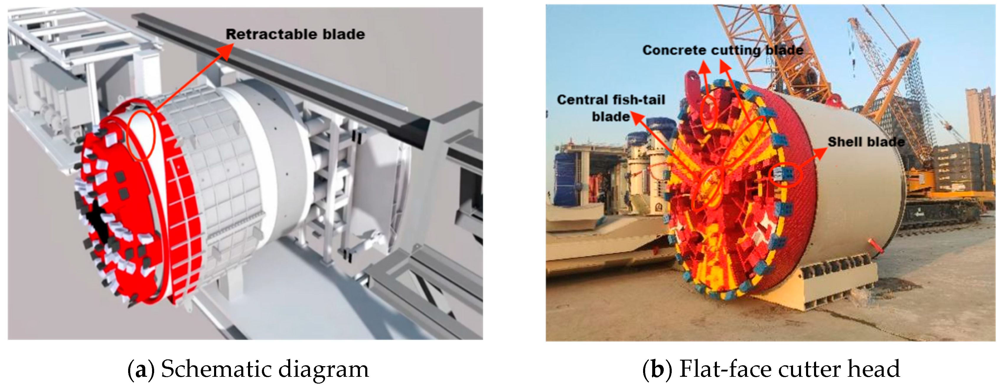
Recently, our research group put forward a cross-passage construction method of ring cutting and push-in. The machine is shown in
Figure 1. With the innovative technology of ring cutting and segment assembly, the construction can not only complete the excavation of cross passages safely and efficiently, but also control the surface settlement of ground well, which will obtain better social and economic benefits. And it is suitable for the construction of the cross passage for the shield tunnel section in the water abundant area, especially for the projects of cross passage with poor soil stability, short construction period, and high environmental protection requirements.
From the background above, most of previous research is based on steady-state analysis of different stages of construction by mechanical method. It is considered that more dynamic analysis of the construction process should be investigated. Meanwhile, different from the current research and analysis of cutting the main tunnel using arc cutter head, the study analyzes the main tunnel hole breaking using flat-face cutter head. Therefore, based on the engineering background of Jingrong Street station- Kunjia Road station of Suzhou Metro Line 11, the numerical simulation is conducted to study the mechanical response of the segments in the construction of the flat-face cutter head pushing method, which could provide some engineering application suggestions.
2. Project Overview
The design boundary mileage of Jingrong Street Station—Kunjia Road station is from R DK26 + 567.115 to RDK27 + 636.075, with short chain of 1.041 m and length of 1067.919 m. Left line mileage is from LDK26 + 567.115 to LDK27 + 636.075, with short chain of 1.247 m and length of 1067.713 m. The total length of the left and right line tunnel is 2135.632 m.
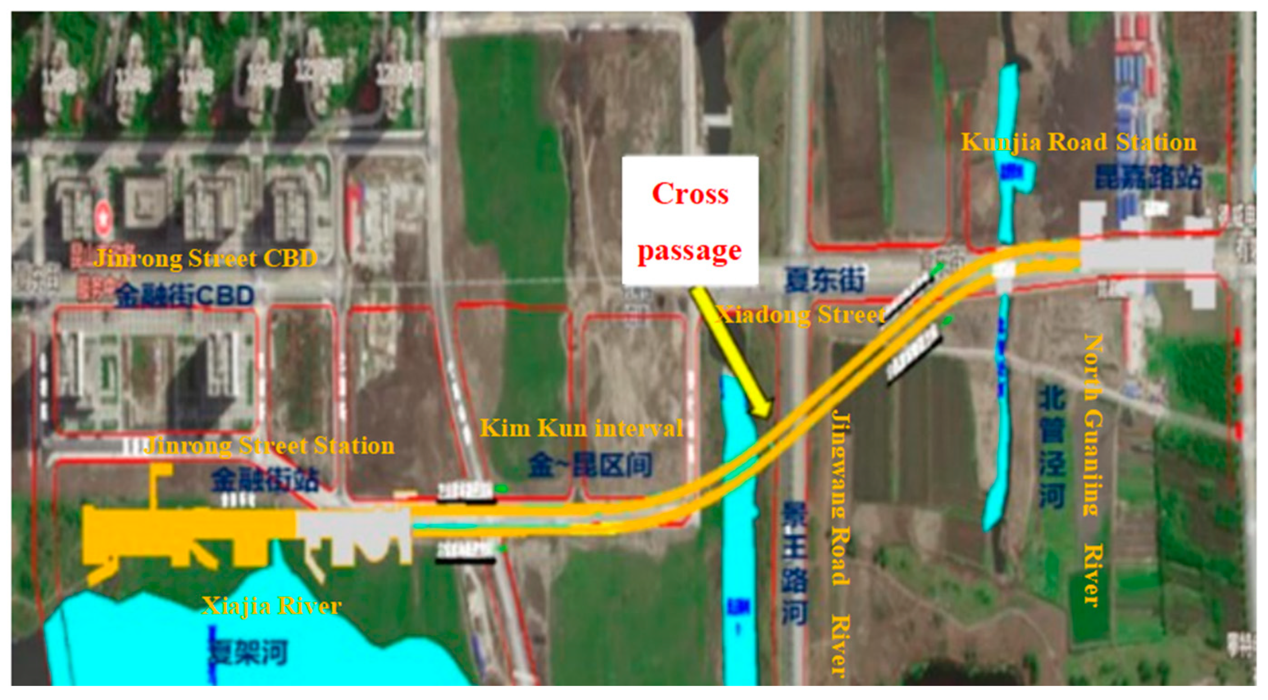
After leaving Jingrong Street Station, the left and right lines of the tunnel run south through the current open space and pass under the planned road. The plots on both sides are planned commercial and residential areas. The left and right lines turn left at a curve with a radius of 700 m and pass under Jingwang Road, continue to run southeast, pass under the current farmland and turn under Xiadong Street with a curve with a radius of 500 m. To the south through the North Guanjing Bridge and the side through the 110 kv power pipe tower to reach the Kunjia Road station. The left and right lines are constructed by the shield tunneling method. As shown in
Figure 2, a cross passage and pump house is set up in the mileage of RDK27 + 139.123.
The cross passage is located under Jingwang Road, where there is no structure on the ground. The center mileage of the left and right line shield tunnel at the cross passage is LDK27 + 149.198 (RDK27 + 154.500), the center distance of the tunnel at the cross passage is 13.0 m, and the elevation of track surface of the left and right line tunnel is −19.131 m and −19.129 m, respectively. The ground elevation is about +2.60 m. The covering soil thickness of the tunnel in this section is 8.6~16.3 m. The structural form of the section is the circular tunnel assembly segment of shield method. As shown in
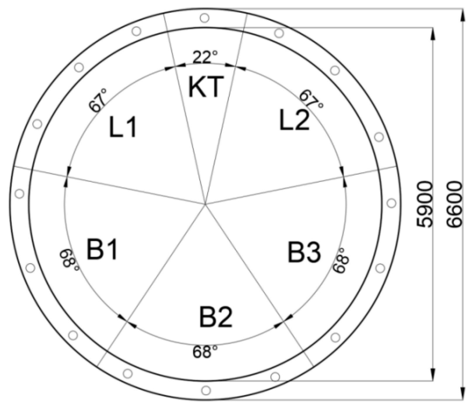
Figure 3, the inner diameter of the segment rings is 5.9 m, with the outer diameter is 6.6 m. The width of the standard ring is 1.2 m, while the width of the special ring for the cross passage is also 1.2 m.
The cross passage is located under Jingwang Road, where there is no structure on the ground. The center mileage of the left and right line shield tunnel at the cross passage is LDK27 + 149.198 (RDK27 + 154.500), the center distance of the tunnel at the cross passage is 13.0 m, and the elevation of track surface of the left and right line tunnel is −19.131 m and −19.129 m, respectively. The ground elevation is about +2.60 m.
3. Numerical Modeling
To study the mechanical response of the segment during the cutting process of the main tunnel cross passage by using the flat-face cutterhead, the three-dimensional model of the six rings of the main tunnel with a cross passage established by using finite element software for numerical simulation analysis.
Abaqus/Explicit 2021 is chosen for numerical simulation analysis in this paper because of its powerful computing power and universal simulation function. Establishing a corresponding three-dimensional model of the six-ring main tunnel in the part module, apply external pressure in the load module and define the rotation speed and thrust speed for the cutterhead, select the dynamic explicit analysis step in ABAQUS and calculate.
3.1. Establishment of the Finite Element Model
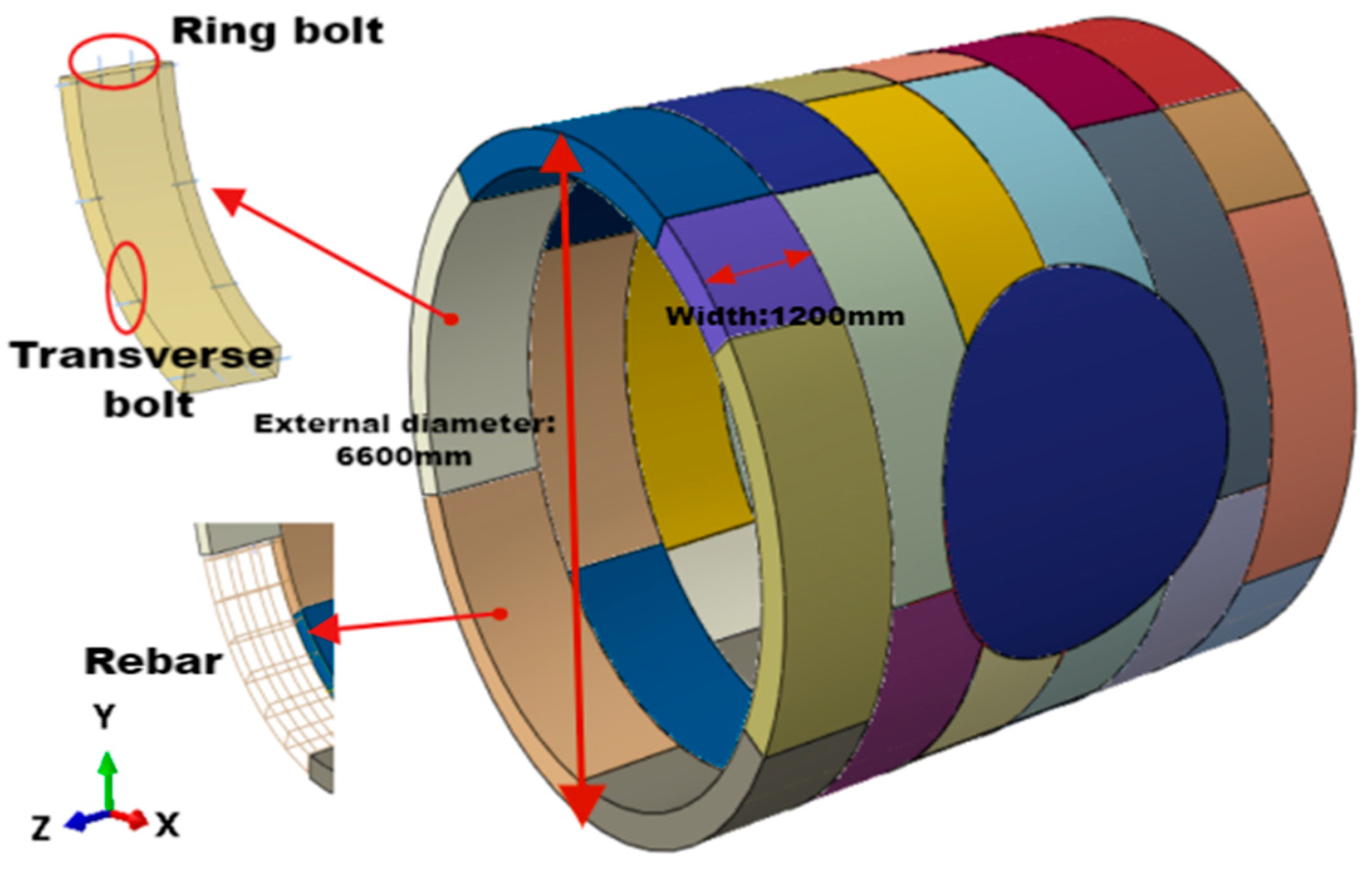
Reinforced concrete pipe segments are used to assemble the tunnel model according to the actual project, as shown in
Figure 4 and
Figure 5. Each ring segment is divided into six blocks along the ring direction, namely three standard blocks (B1, B2, B3), two adjacent blocks (L1, L2), and one capping block (KT). The outer diameter of the segment is 6.6 m, the width of the segment is 1.2 m, and the thickness is 0.35 m. The reinforced concrete segment is with strength grade of C50, and part of the segment is made of steel-mixed special segment. The steel reinforcement has a strength grade of HPB300 and HRB400.
The tunnel portal is made of concrete grade of C50, and the inner steel plate around the tunnel portal is as shown in
Figure 3. The tunnel segments are assembled with straight ring and wedge turning ring with double-sided wedge. The wedge quantity is 39.6 mm and the angle is 0.3437706°. The pipe segments are connected by straight bolts and bent bolts. Surface contact is used to connect different parts of the model. To simplify the processing, bolts are set as beam units embedded between concrete segments. As shown in
Figure 5, the steel reinforcement cage is positioned by rotation in the assembly module and embedded into the segments, respectively.
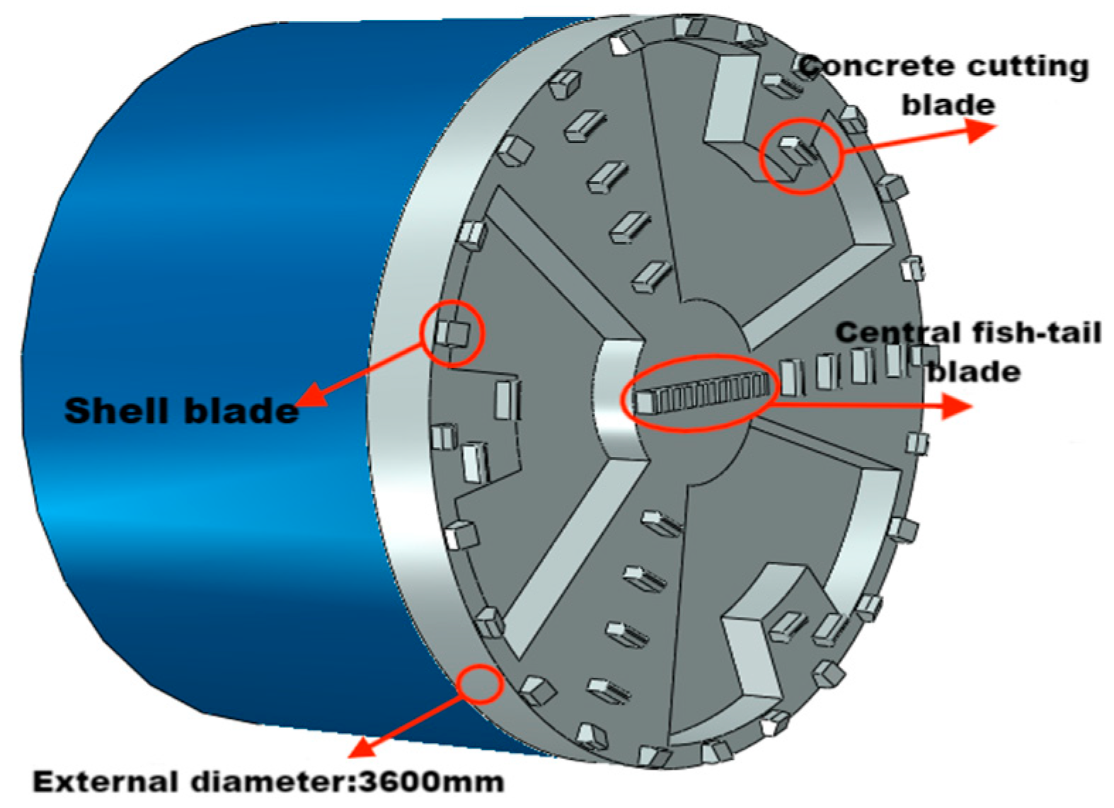
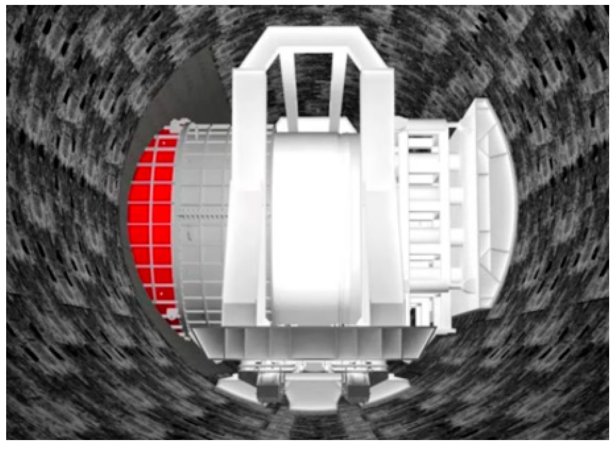
The excavation diameter of the tunneling machine is 3300 mm, and the flat-face cutterhead on the tunneling machine consists of one center fish tail cutter, 24 shell cutters, and 18 concrete cutters. The finite element model is shown in
Figure 6.
3.2. Material Structure and Parameters
The structural material parameters are shown in
Table 1.
To reflect the damage variation in concrete segments in the simulation, the constitutive model of Concrete Damaged Plasticity (CDP) is applied for the concrete segments [
16]. When concrete is in the linear elastic stage, the material is in a non-damaged state, but when the material enters the yield stage, the damage factor is introduced to reduce the elastic modulus of concrete, and the stress–strain relation is as follows:
where
denotes the stress tensor; d is the concrete damage factor (
);
is the total strain tensor;
is the plastic strain of concrete;
is the initial elastic modulus of concrete.
The damage factor is calculated using the strain energy calculation method with reference to the classical damage theory of Najar, the calculation method is as follows:
where
is the Gauss integral of strain corresponding to the stress from the original point to the peak stress on the stress–strain curve of concrete.
The values of d range from 0 to 1. And 0 and 1 represent the initial no damage state and the theoretical complete damage state, respectively. In general, a damage factor is generally defined before approaching 1, which is set as the damage threshold of material progressive failure. The mesh that reaches the damage threshold in the software calculation will fail and automatically exit the calculation.
The linear elastic constitutive model is used for the steel-concrete composite segments. According to the classic Halpin-Tsai model, the steel-concrete composite segments are simplified to short fiber composite materials, and their equivalent elastic modulus is obtained by the following formula [
17]:
where
E is the equivalent elastic modulus of composite material;
Em is the elastic modulus of steel segment;
Ef is elastic modulus of concrete;
is the reinforcement degree of steel segment;
Vf is the volume specific gravity of steel fiber in the segment.
The Drucker-Prager (D-P) constitutive model is applied for the concrete material of the cutting portal. The D-P model is widely used in brittle materials such as rocks, ceramics and concrete, which can reflect the change trend of the strength characteristics of brittle materials under multi-axial stress. The Shear Damage model is selected to define damage, and the combination of damage and fracture is used for cutting brittle materials. In addition, the process of cutting tool is realized by setting the advancing speed and rotation speed of the tool model. The advancing speed is 0.05 mm/s and the rotation speed is 1 RPM. The damage threshold is set for the concrete material of the machinable tunnel portal. Make the material at the hole door under the cutting action of the cutter head, when the material reaches the damage point, the unit is automatically deleted and exits the calculation.
3.3. Analysis of Working Conditions
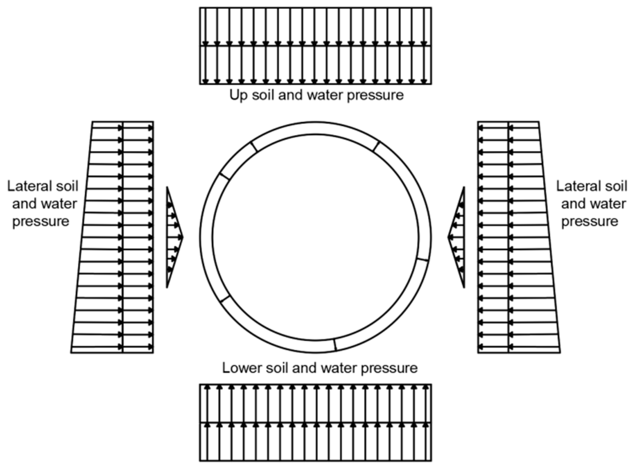
The load-structure method is adopted for analysis, and the displacement constraint of land on the tunnel boundary is established, and the two ends of the tunnel are fixed constraints. The loads considered by T joint include soil load, water pressure and material weight. The condition at starting stage is shown in
Figure 7. And the calculated external load is applied as shown in
Figure 8.
At the stage of initial working conditions, the main tunnel naturally deforms to a stable state under the action of external water and soil pressure. Then, at the stage of pre-support condition, the inner support system starts to work, and the support force is transferred to the segment at the vault and bottom of the arch through the upper and lower support boots. At the next stage of cutting conditions, the machine began to excavate; at the same time, the segments behind the cutting direction were affected by the reaction frame. And the total reaction force of the reaction frame is set as 1000 kN. The cutter head begins to act on the tunnel portal until the concrete of the tunnel portal is completely grinding and spalling.
4. Analysis of Numerical Calculation Results
With the calculation software, the explicit dynamic calculation is used to obtain the simulation results of the initial fracture of the flat-face cutterhead, and the construction mechanical characteristics are analyzed.
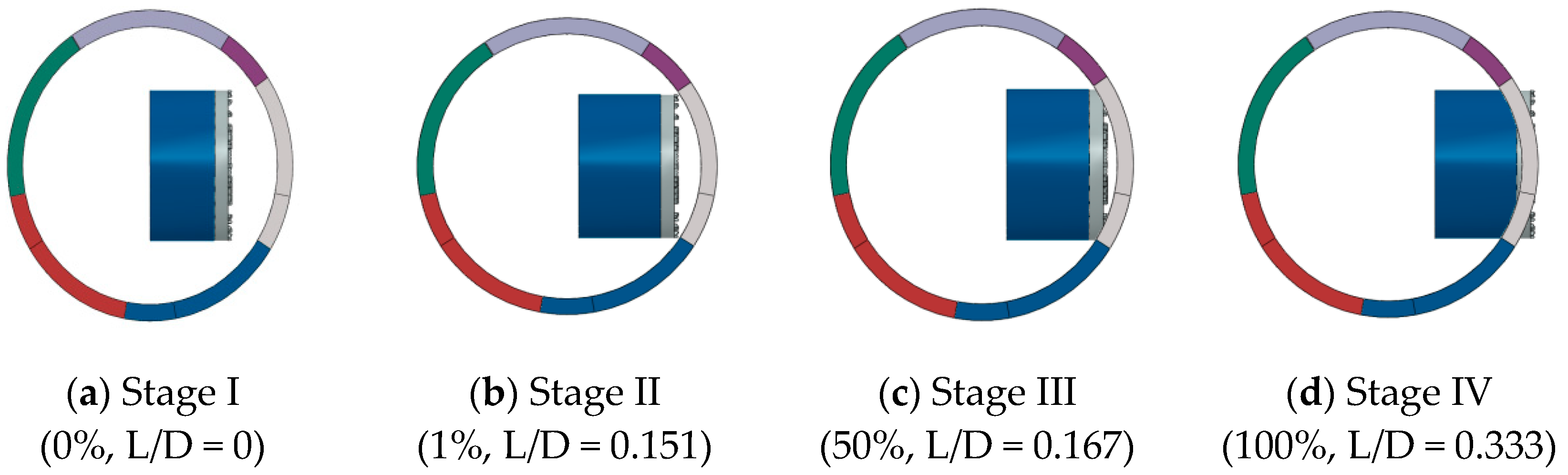
To fully reflect the construction mechanics characteristics of the main tunnel segment of the cutter head grinding, as shown in
Figure 9, four analysis stages are set up: stage I, stage II, and stage III and stage IV. And the cutting process in percentage and the ratios of the cutter displacement to the tunnel diameter (L/D) also represent the states.
In the first stage, the double-track tunnel was completed and the cross passage had not been excavated, and the tunnel was subjected to stratum load. In the second stage, after the operation of the internal support system, the top bracing force generated by the oil cylinder is transmitted to the pipe segments by the bracing boots. In the third stage, the hole portal is ground from the cutter head until the upper and lower parts of the hole are penetrated by the cutter head. In stage IV, the segments of the tunnel portal are completely grinded. The cutting process in percentage has been marked. And 0% represents before cutting, while 100% represents that the portal has been totally cut through.
4.1. Deformation Analysis of Main Tunnel
Due to the symmetry of the main tunnel segment rings, the semi-cut ring and the fully cut ring on one side are selected, and the construction mechanical characteristics of them under the cutting action of the cutter head are analyzed.
Figure 10 shows two different segment rings: the segment ring cut by the cutter head center tool is completely cut off, which is the fully cut ring. Only a small part of the segment ring cut by the tool on the left and right edge of the cutter head is cut off, which is the semi-cut ring. Because the construction mechanical characteristics of the two are different, the mechanical data of the two kinds of segment rings are extracted in the post-processing, and the mechanical characteristics of the semi-cut ring and the fully cut ring are compared and analyzed.
4.1.1. Deformation of Tunnel Main Tunnel Lining Grinded by Flat-Face Cutter Head
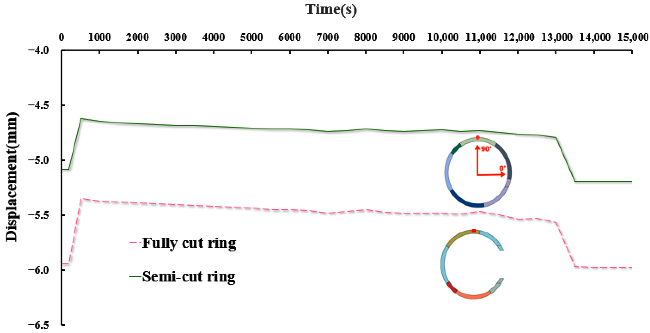
Firstly, the displacements of fully cut ring and semi-cut ring segments in four different construction stages are extracted.
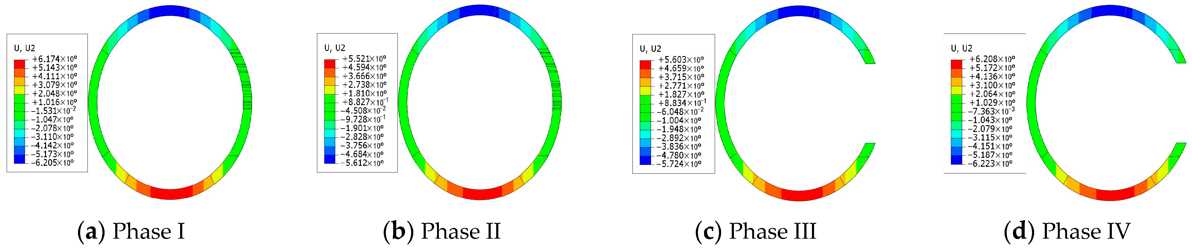
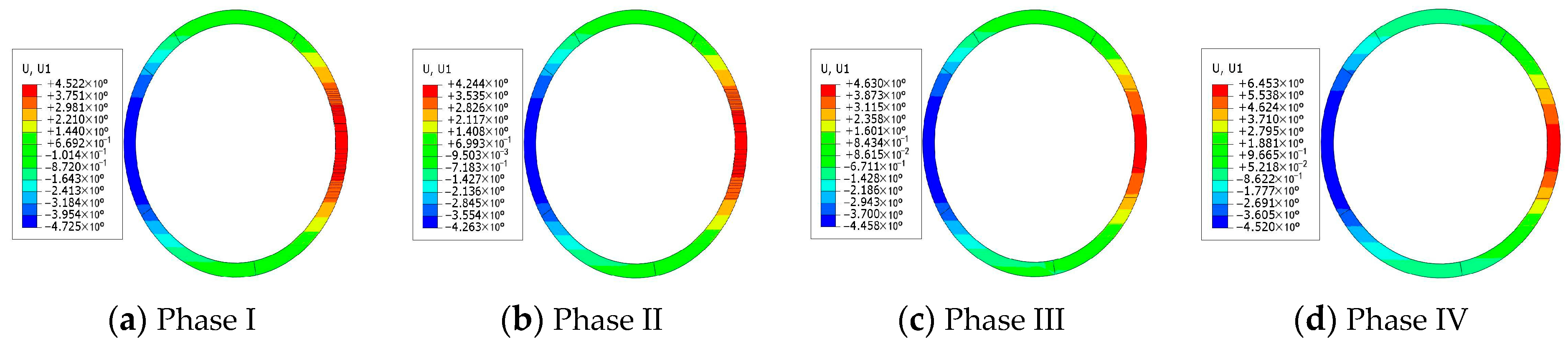
For the fully cut segment, as seen in
Figure 11 and
Figure 12, the maximum displacement in the horizontal direction occurs in stage I, the maximum displacement in the vertical direction occurs in stage IV, the maximum displacement values are 5.812 mm, 6.223 mm, respectively. In stage I, the segment is subjected to soil and water pressure, and the maximum displacement appears in the vertical direction. In stage II, the internal support system begins to function, and the displacement of the segments under the support of the bracing boots is reduced. With the continuous driving of the cutter head, the cutter head gradually grinds the concrete of the tunnel door, and the displacement of the segment in the horizontal direction increases due to the jack-up action of the cutter head to the tunnel door and the reaction force of the reaction frame. After the tunnel is constructed, the top and bottom of the tunnel are squeezed by water and soil pressure, and the displacement increases further.
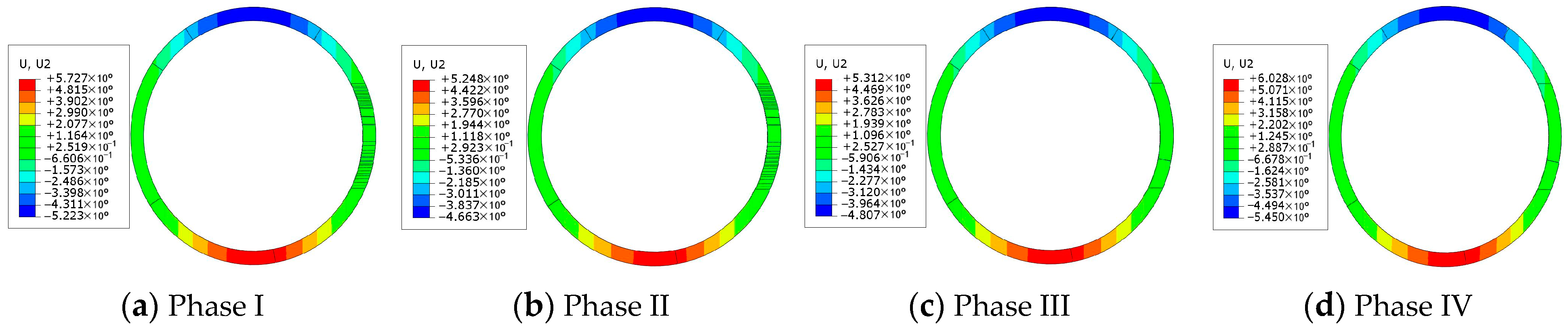
From the results of
Figure 13 and
Figure 14, it can be seen that the maximum horizontal and vertical displacement of the semi-cutting ring occurred in Stage IV, the maximum displacement values were 6.453 mm and 6.028 mm. Because the B3 segment on the semi-cutting ring is in contact with the waist of the tunnel door, the disturbance generated by the cutter head driving has a greater influence on it. Therefore, the lateral displacement of the B3 segment on the semi-cutting ring in contact with both sides of the tunnel portal is larger. In the vertical direction, the displacement of the semi-cut ring and the fully cut ring is relatively close. Overall, none of them exceeded the maximum allowable displacement values of 30 mm in design code [
18].
4.1.2. Displacement Comparison Between Different Rings
To study the change in displacement of the two cutting rings throughout the cutting process, since the larger values of displacement are mainly found in the top, bottom and waist of the tube ring, the displacement of semi-cutting rings and full-cutting ring is compared to each of these three locations.
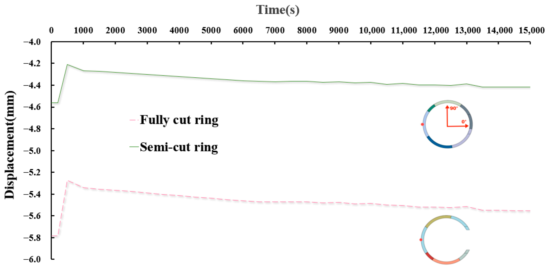
As can be seen from
Figure 15, the displacement of the fully cut ring is large in the direction of 180°, with a maximum displacement of nearly 5.8 mm. After the tube sheet is supported, its displacement is significantly small, reducing the earth arch effect to a certain extent. After the blade began digging, the displacement in this direction began to increase and gradually stabilized. The displacement of the semi-cut ring in the direction of 180° is small, and its overall pattern of change is similar to that of the fully cut rings, but the displacement is smaller than that of the fully cut ring.
As shown in
Figure 16, at 90° angle, the displacement of the fully cut ring is greater than the displacement of the semi-cut ring. A pre-support system greatly decreases the displacement of the top of the tube ring. After the cutting begins, the top shift in the two rings gradually increases with the cutting. It is worth noting that the top of both rings produced a significant displacement downward when the cave opening was to be opened. After the hole was opened, the displacement stabilized.
As shown in
Figure 17, at the direction of 270°, the displacement laws of the fully cut ring and the semi-cut ring are still approximate. Among them, the fully cut ring has a larger displacement. After the advance support, the displacement of the two is reduced, and the displacement gradually increases after the shield machine begins to cut. Like the displacement at the top of the tube ring, the bottom of the tube ring creates a larger displacement to the inner side of the tunnel as the portal is nearly opened.
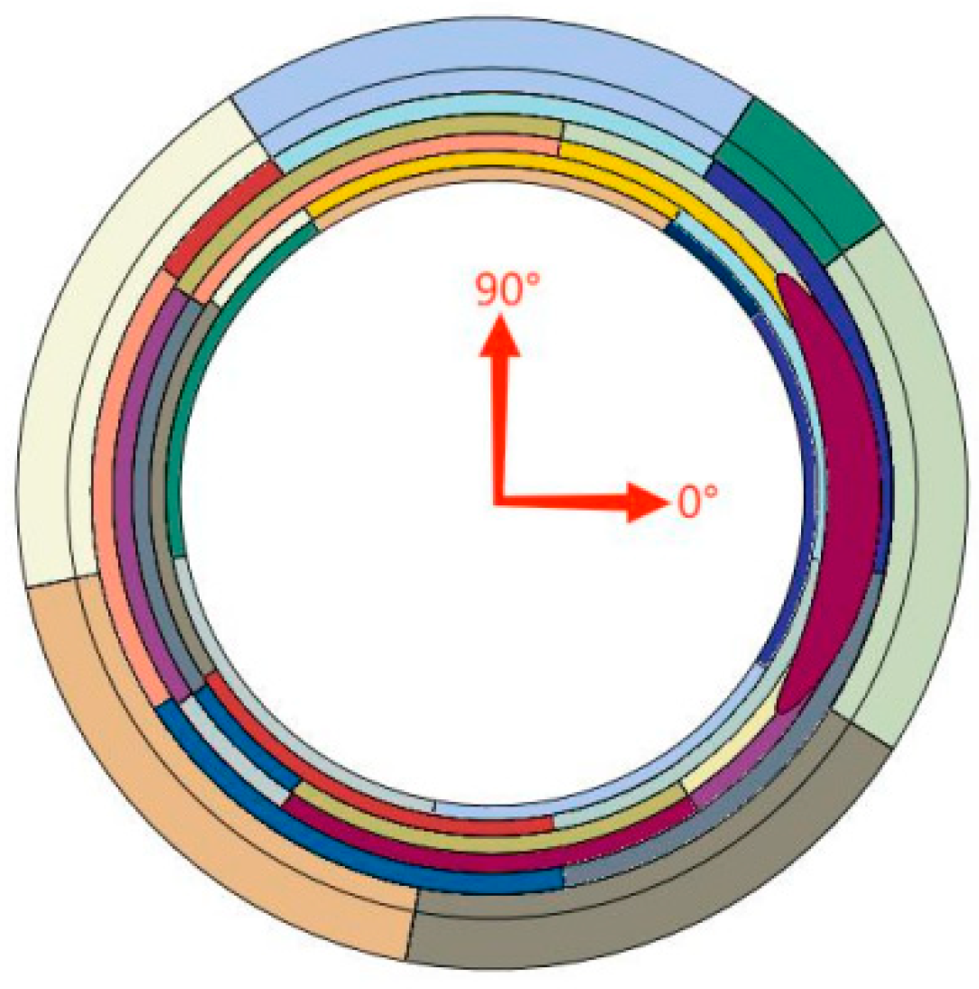
4.2. Displacement Analysis of Measuring Point
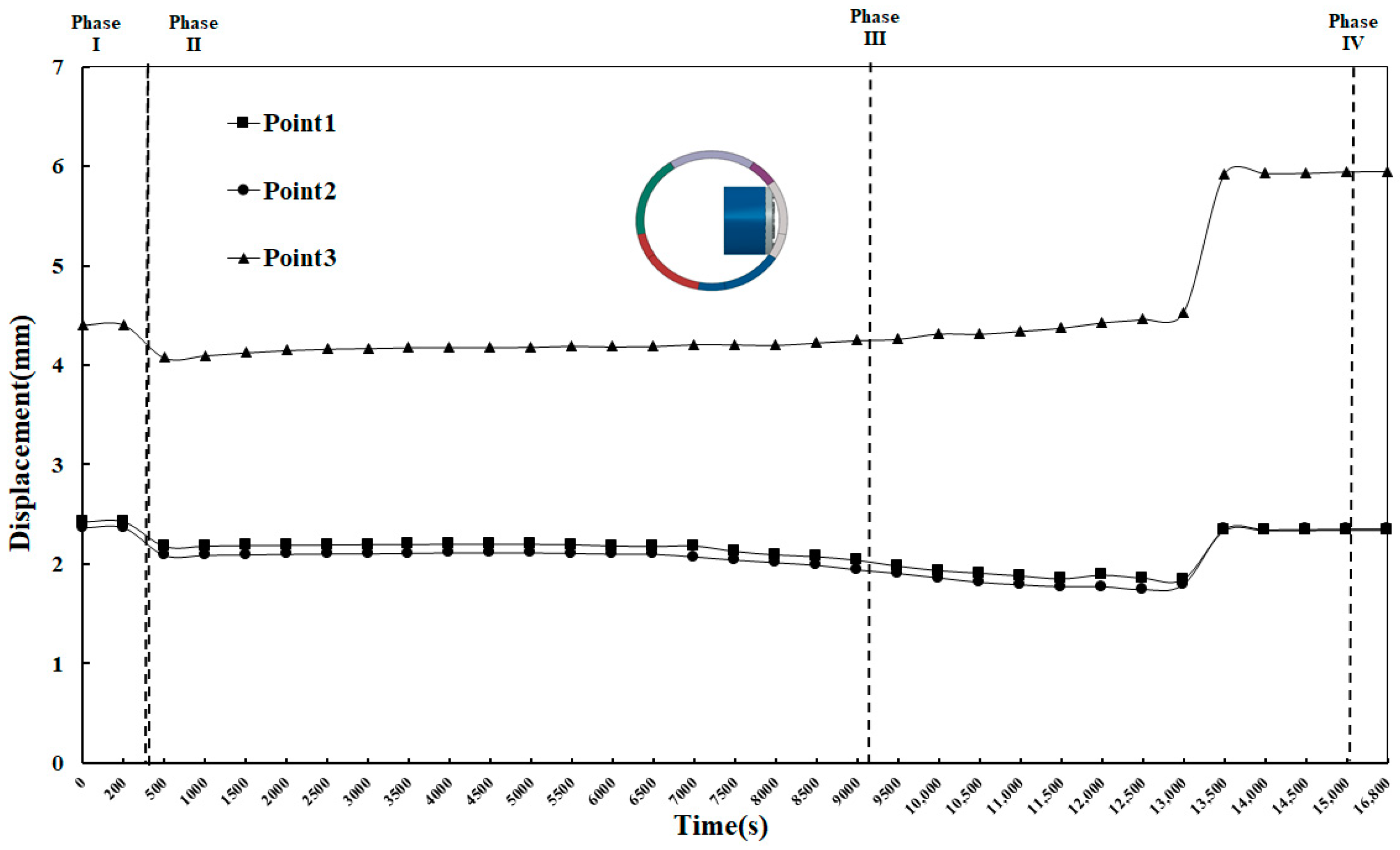
According to the results of the processed cloud image, the segment displacements of the fully cut ring and the semi-cut ring in the four construction stages are analyzed above. To further analyze the regularity of segment displacement, after the main tunnel is holed, measuring point 1, 2, and 3 as shown in
Figure 18 are, respectively, taken for research. The displacement data graphs of the three points in the x and y directions are obtained.
Under the action of soil and water pressure, the main tunnel is compressed and presents as the shape of a flat duck egg. As shown in
Figure 19, the three measuring points are offset towards the outside of the main tunnel. And the displacement of the points decreases after the internal support system works. With the continuous excavation of the cutter head, the displacement of measuring point 3 increases gradually and reaches the maximum value after the hole is broken. After entering Phase III, the upper and lower parts of the tunnel portal are worn through, and the segments of the upper and lower parts of the tunnel door are squeezed by earth pressure and the reverse thrust of the reaction frame, and the measurement points 1 and 2 begin to move towards the inner side of the main tunnel, and the horizontal displacement reaches the maximum in the tunnel forming stage.
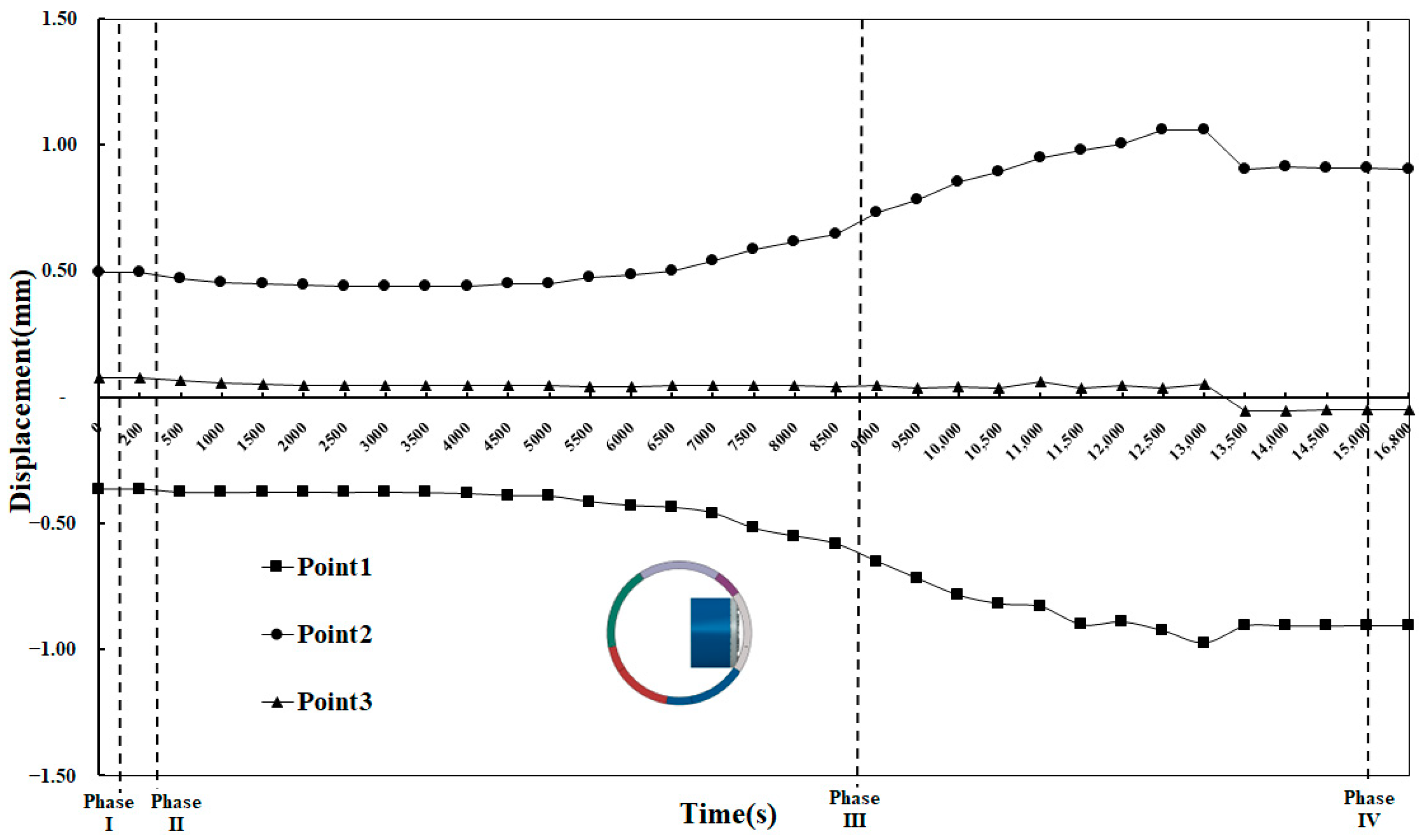
In terms of the displacement of Y direction (as shown in
Figure 20), in the first stage, soil and water pressure moved measuring points 1 and 2 to the inside of the tunnel. After the second stage, with the cutter head starting to cut the tunnel portal, the displacement trend of measuring point 1 and 2 are significant, and the displacement gradually increased. From the third stage when the upper and lower parts of the tunnel door have just been worn through to about 15,000 s, the displacement of the first and second measuring points are increasing. When the concrete in the waist of the tunnel door was about to be destroyed, the pushing force of the shield machine is small, and the displacement of each measuring point in the vertical direction is also reduced. After the hole is formed, the displacement of the points tends to be stable.
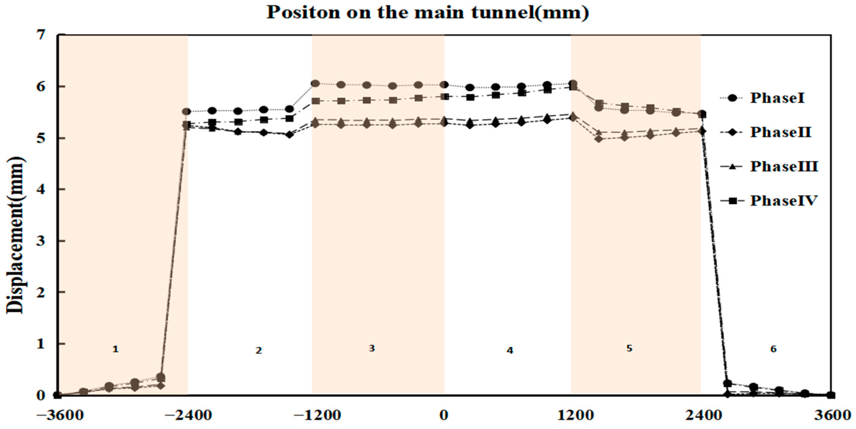
4.3. Displacement Analysis Along the Direction of the Main Tunnel
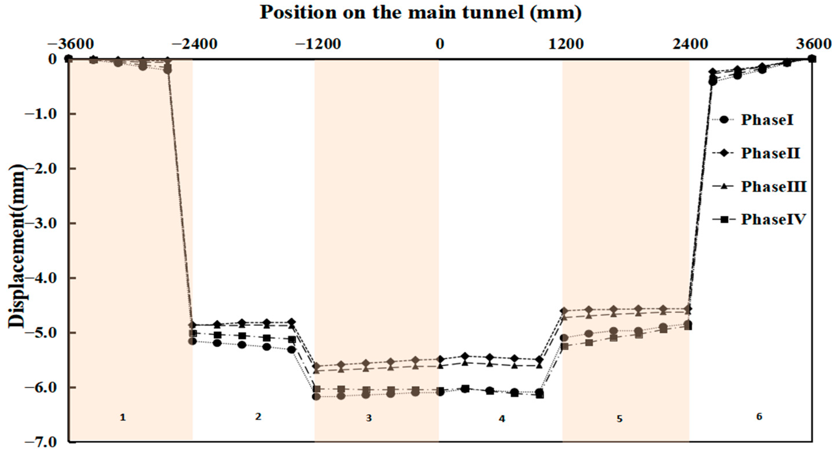
To study the influence of the mechanical cutting process on the displacement of the main tunnel, the vertical displacements of the segments at the top and bottom of the main tunnel along the direction of the main tunnel were analyzed. And the horizontal displacements of waist on both sides of the main tunnel were analyzed as well.
4.3.1. Displacement at the Top of the Main Tunnel
As shown in
Figure 21, the displacements of the two rings of segments farthest from the center of the main tunnel are relatively small, while the displacements of the two rings of segments at the center of the main tunnel are the largest. After the pre-support in the second stage, the vertical displacement at the top of the tunnel was controlled, and the pre-support system played its role. After entering the cutting stage, the vertical settlement at the top of the main tunnel gradually increased with the progress of cutting.
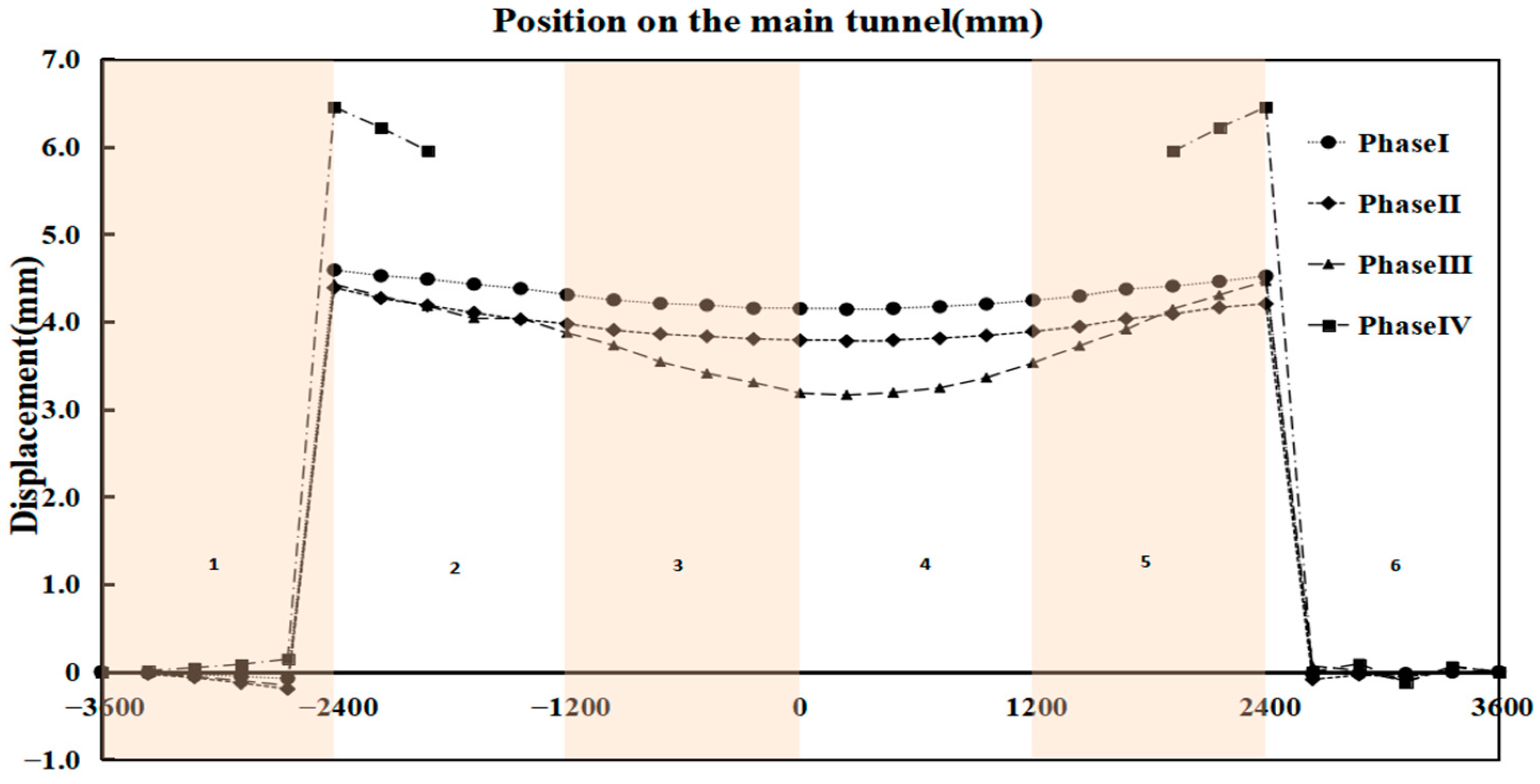
4.3.2. Displacement at the Bottom of the Main Tunnel
In
Figure 22, we can see that, similar to the vertical displacement of the top of the main tunnel, the vertical displacement of the bottom of the third and fourth ring segments is the largest. Because of the existence of the joint surface, the displacement of the bottom of the second to fifth ring segments is also large. In addition, the pre-support also effectively controlled the displacement at the bottom of the main tunnel.
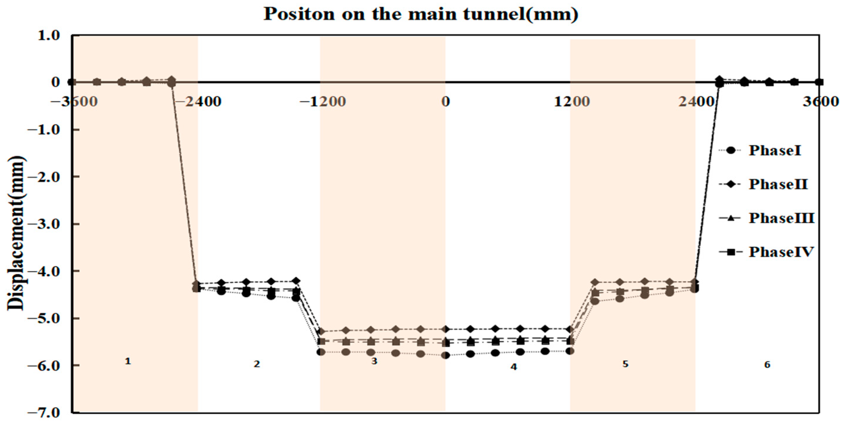
4.3.3. Displacement at the Waist of the Main Tunnel
Based on the compression effect of water and soil pressure on the tunnel, the displacement of the waist on both sides of the tunnel should be analyzed emphatically. It can be seen in
Figure 23 that the displacement of the main tunnel segment on the horizontal side of the tunnel door is relatively consistent except for the tunnel working condition. The displacement of the segments on both sides of the openings is larger due to the thrust action of the shield cutter head on the tunnel entrance. With the jacking of the cutter head and the destruction of concrete at the entrance, the water and soil pressure at the entrance act further, and the waist of the tunnel has a large displacement in the horizontal direction.
As shown in
Figure 24, the displacement trend of the back side of the main tunnel is relatively regular, and the horizontal displacement of the waist on the back side gradually increases with the excavation of the cutterhead. Among them, the horizontal displacement of the third and fourth ring is greater than that of the other segments due to the action of the support frame. It could be suggested that the soil near the top and waist of the second to fifth ring should be reinforced with emphasis.
4.4. Internal Force Analysis
The direction of the internal force analysis for the segments is shown in
Figure 25. And
Figure 26 and
Figure 27 show the axial force distribution of full-cutting ring and semi-cutting ring tube in different construction stages, respectively.
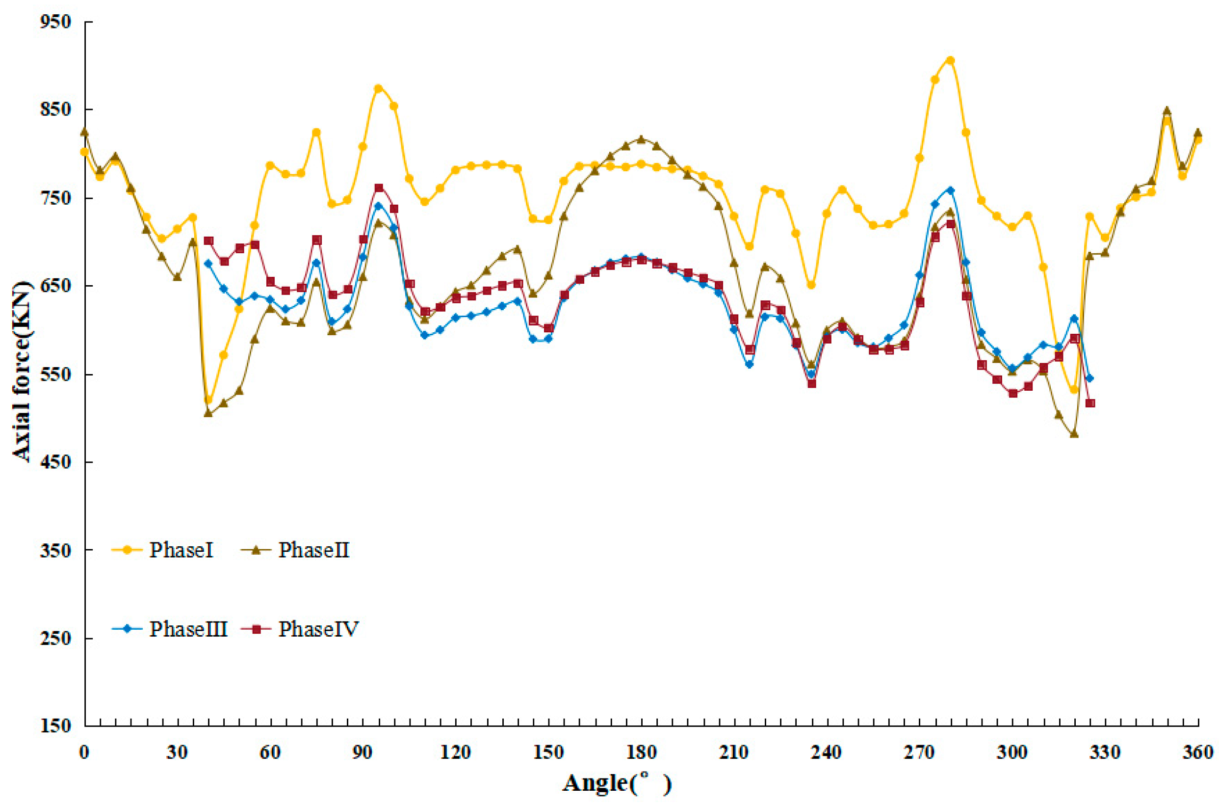
It can be seen from
Figure 26 that the axial force at the top and bottom of the fully cut ring is larger than that at the waist of the fully cut ring, andsmaller before the cross passage is excavated. During the second stage, upon the application of the pre-support, the axial force of the cutting ring is changed, and the structural force is thereby enhanced. At the same time, the phenomenon emerges that the axial force at the waist becomes larger and that at the top and bottom turns out to be smaller because of the pre-support system. In the third stage, the cutterhead penetrates the upper and lower parts of the portal, which changes the stress state of the whole cutting ring again to a certain extent, resulting in a situation where the axial forces at the top and bottom of the ring are large and the axial force at the waist is small. In the fourth stage, with the completion of grinding the concrete at the portal, the bearing capacity of the portal weakens, and the fully cut ring is obviously affected by the vertical water and soil pressure, leading to changes in the level of the axial force. However, the change in the axial force at the waist is rather insignificant.
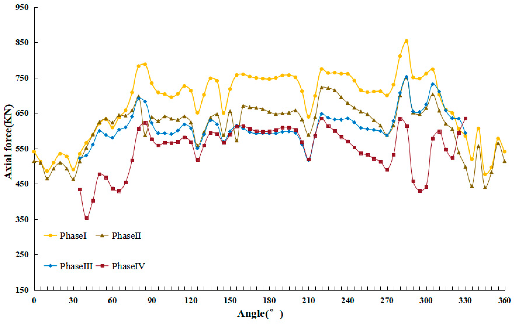
Compared with the fully cut ring, the axial force level of the semi-cut rings is smaller, and its axial force variation pattern is different. Shown in
Figure 27, for the semi-cut ring, the axial force at the waist on one side of the portal is the smallest, while the axial forces in the other three directions are relatively larger. From the second stage to the third stage, after the upper and lower parts of the tunnel portal were polished by the cutterhead, the overall axial force of the semi-cut ring shows little change. However, the axial force in the segment on the back side of the driving direction began to decline. In the fourth stage, due to the completion of the portal, the lateral water and soil pressure on one side of the tunnel varies, and the axial force of the semi-cut ring on this side also decreases correspondingly. Meanwhile, the axial force in the segment on the back of the driving direction remains basically unchanged.
4.5. Analysis of Bending Moment of the Segment Ring
The fully cut and semi-cut ring in the main tunnel were selected for bending moment analysis. Around the fully cut ring, every 5° was taken as a section, while the resultant bending moment of the section was calculated. The bending moment diagram of the fully cut and semi-cut ring at four different stages is obtained as shown in
Figure 28 and
Figure 29.
According to the bending moment value, the bending moment value of the semi-cut ring is larger than that of the fully cut ring. The maximum bending moment occurs at the waist of the portal. The pre-support system alleviates the compression and bending of the segment reasonably and reduces the bending moment in the segment. In the third stage, with the exception that the upper and lower parts of the door have been penetrated, the cutter head has been grinding towards both sides at the back of the portal. Because of the larger contact surface between the cutting portal and the semi-cut ring, the disturbance of the semi-cut ring is prominent during the jacking process of the cutterhead. And the sudden change in the bending moment of the semi-cut ring within the range of 45° above and below the arch waist is more conspicuous than that of the fully cut ring, and the bending moment value is also larger. In the fourth stage, the cutter head of the shield machine successfully cut through the portal ceased its contact with the segment. This led to a change in stress state of the segment, and the bending moment in the segment rings increased under the influence of external pressure.


