Article

Methods and Means of Eddy Current Testing of Soldered Lap Joints of Electrical Machines

1
Department of Metrology, Instrumentation and Quality Management, Saint-Petersburg Mining University, 2, 21st Line, St. Petersburg 199106, Russia
2
LLC. “KONSTANTA”, 21, Ogorodny Lane, St. Petersburg 198095, Russia
*
Author to whom correspondence should be addressed.
Appl. Sci. 2025, 15(4), 2036; https://doi.org/10.3390/app15042036
Submission received: 13 January 2025 / Revised: 10 February 2025 / Accepted: 13 February 2025 / Published: 15 February 2025

Abstract

:
This article is devoted to the non-destructive testing of the soldering integrity of soldered lap joints of the current-carrying busbars in electrical machines’ stator windings. The design of a two-element eddy current probe with tangentially positioned coils and active shielding for measuring the soldering integrity of soldered lap joints is developed. This paper considers the method of suppressing the influence of stray parameters on the testing results and the method of correcting the measurements in the case of a deviation in the electrical conductivity of the conductive busbar material. The test results demonstrate the performance of the developed eddy current probe for determining the actual value of the soldering integrity of soldered lap joints in the range of 0–100% with a permissible relative error of no more than 5%.

1. Introduction

In the design of stators for some types of high-power turbine generators, the electrical connection of current-carrying windings is ensured through soldered lap joints with intermediate copper busbars. Ensuring the reliability of such connections is one of the most important tasks in the manufacturing and repair of electrical machines since dry solder joints lead to a decrease in the area of electrical contact, i.e., a decrease in the cross-section of the conductor and an increase in its electrical resistance. When high currents flow through a conductor with high resistance, a significant amount of heat is generated, which can melt the solder of the solder joint, leading to further destruction of the connection. Defects in connecting busbars lead to power losses and cause a quarter of all accidents and generator failures [1,2]; therefore, the task of quality testing of these connections is important and relevant.

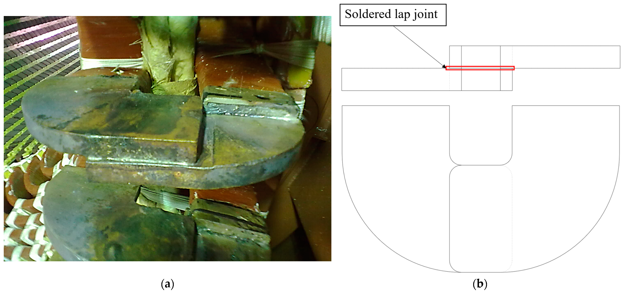
1.1. Description of the Test Object

The test object (TO) is a soldered lap joint of two plates made of electrical copper, Cu-ETP [3], with the use of tin–silver solder, applied to the entire overlapping area of the two plates, which can be accessed from three sides, Figure 1a. The tested zone of the TO is the overlapping area of the busbars, Figure 1b. The test parameter is the soldering integrity of the joint, expressed as the ratio of the area of the electrical contact between the plates to the overlapping area of the plates. An important influencing factor is the position of the TO in the front part of the stator, where, in a relatively small volume of space, a large number of inspected joints are located. The aim of testing is to measure the soldering integrity of the TO.

1.2. Methods of Non-Destructive Testing of Soldered Joints
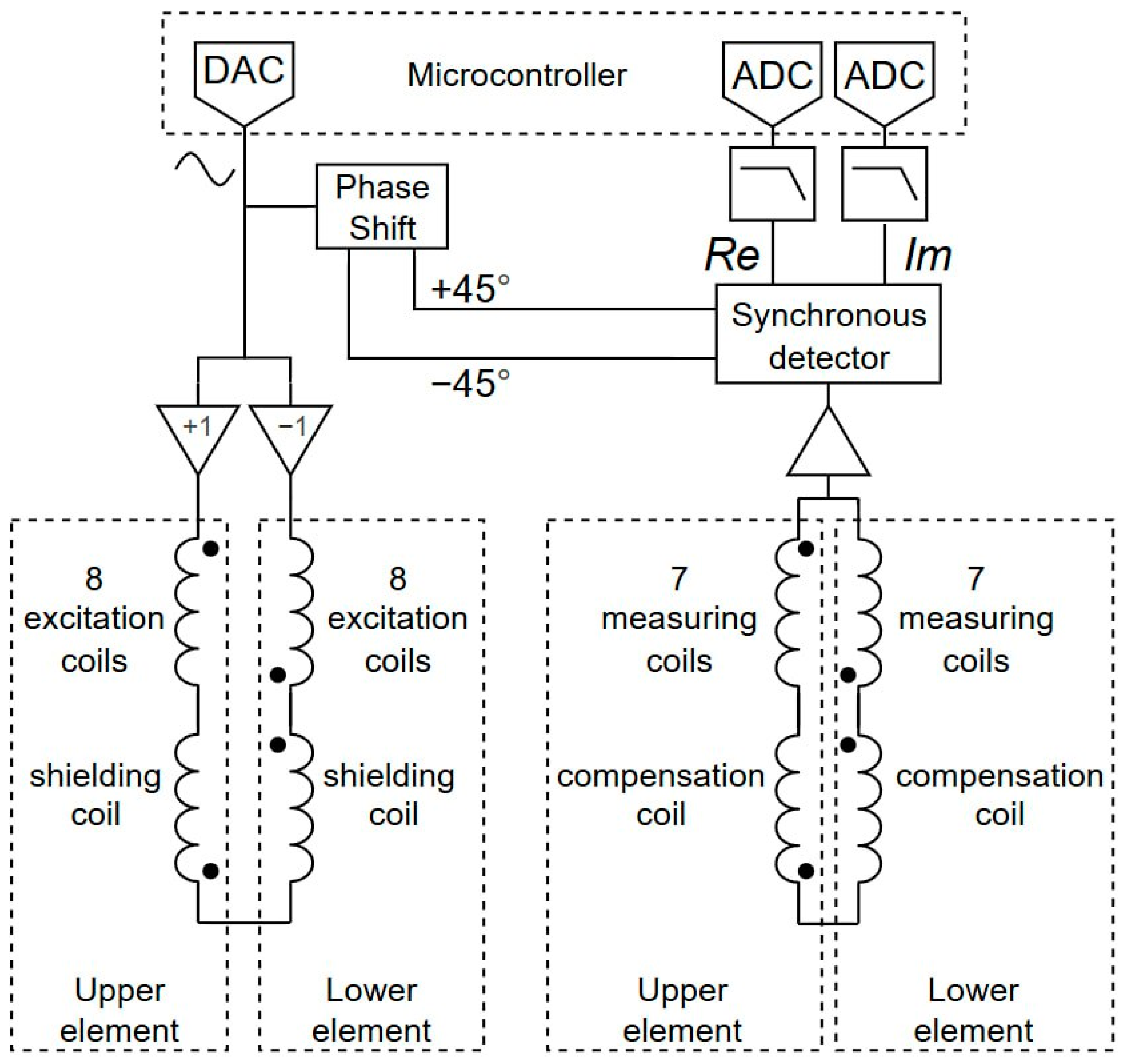
Let us consider the applicability of known methods of non-destructive testing according to [5]. Visual inspection and penetrant inspection are currently used for assessing the quality of soldered lap joints; however, they are only applicable for finding surface defects and leave internal discontinuities undetected. Generally, the detection of unsoldered joints is currently performed using electrical, thermal, or thermography inspection. Since soldering defects in joints result in increasing the resistance of conductors, when an operating current is applied to the stator winding, local overheating develops in an unsoldered joint. The temperatures of unsoldered joints are generally 5 °C higher compared to non-defect joints, which can be detected using temperature-indicating paint. These procedures require the thorough preparation of TO surfaces and strict requirements for safety protection measures when operating with high currents. Furthermore, thermal inspection provides insufficient accuracy in testing due to the high thermal conductivity of copper [6,7]. Magnetic particle and radiowave inspections are not applicable due to the nature of the TO material. Radiographic testing is technically applicable; however, it is impossible to place large-sized equipment directly around the TO. Ultrasonic testing methods have a high sensitivity and resolution but require the direct contact of measuring instruments with the TO and careful preparation of the TO’s surface. Moreover, ultrasonic waves over 1 MHz significantly scatter when passing through the TO material, but lower frequencies have lower resolution; therefore, these methods are used limitedly. The eddy current methods [8] provide sufficient sensitivity when inspecting electrically conductive materials and do not require thorough preparation of the TO surface. Defects of products can also be detected under the insulation layer of connecting busbars. Their disadvantages are the strong dependence of eddy current device measurements on the electrical conductivity of the TO material and the requirement for adjustment and calibration samples to simulate 100% soldering of the TO and variations in TO defects for testing signal interpretation.
In a defect-free joint, the generator operating currents flow unobstructed through the entire volume of the joint, evenly distributing the current density over the entire cross-section of the lap joint [9,10]. In the presence of defects, an area of disconnection in the current-carrying connection is formed; thus, the currents are redistributed and encircle the soldering defect, increasing the current density in the reduced cross-section of the conductor. This physical process is similar to the process of eddy current flow in defect-free and defective objects; therefore, the quality testing of current-carrying busbars in turbogenerators should be performed using eddy current methods of non-destructive testing.
It is necessary to take into account an essential feature of soldered lap joints: the expected defects of soldered lap joints are located in the horizontal plane parallel to the plane of installation for the measuring probe on the tested joint.

1.3. Probe Design

Let us consider the applicability of various types of probes for eddy current testing.
Absolute surface eddy current probes (ECPs) are easy to operate and used for one-sided access to the TO [11,12]. When testing the soldering integrity of lap joints, low-frequency surface ECPs with a coil diameter equal to the thickness of the joint are used. Testing is performed by placing the ECP on the side surfaces of the lap joint, which ensures the sensitivity of the ECP to defects in lap joints. However, due to the limitation of the coil size and the high electrical conductivity of the TO material, defects are detected at a relatively shallow depth; therefore, a large untested zone remains in the center of the TO.
When installing a surface ECP horizontally on a soldered lap joint parallel to the solder plane, the coils are positioned perpendicularly to the plane of defects. The respective paths of the induced eddy currents do not cross this plane; thus, surface ECPs are only limitedly applicable for the testing of soldered lap joints.
Screening ECPs differ from surface ECPs due to coaxial positioning of excitation and measuring coils on different sides of TO. Screening ECPs applying the amplitude method demonstrate the ability to test the soldering quality of turbine generator stator cores. However, the reliability is low due to the requirement for accurate ECP positioning relative to the TO [13]. The transition from the amplitude method to the amplitude–phase method with the use of a screening ECP allowed the accuracy of measurements to be increased [14,15,16]. On this basis, a method was developed to assess the quality of soldered joints in electrical machine rods using calibration on two samples of tested joints with soldering integrity values of 0% and 100% [17].
To increase productivity and simplify the testing procedure, an ECP with reference coils was proposed, which implements the phase method while comparing the signals from the reference and measuring coils [18].
Thus, screening ECPs are used for two-sided access to the TO for defect detection at significantly greater depths in comparison with surface ECPs while providing an equal probability of detecting soldering defects throughout the entire volume of the TO. However, a significant disadvantage of screening ECPs is also their sensitivity only to defects in the plane perpendicular to the plane of ECP installation, which makes them inapplicable for the inspection of soldered lap joints.
The eddy current probe DPS-6 (IMP UB RAS, Ekaterinburg, Russia) with a U-shaped probe is designed to detect soldering defects in winding bars of electrical machines [19]. This probe consists of a parametric coil, operating as both excitation and measuring coils, wound on a U-shaped core and composed of transformer steel plates. The developed device and methodology allow for the detection of soldering discontinuities in current-carrying rods. On this basis, a method of testing current-carrying bars in high-power superconducting magnets was later developed [20], including calibration on two soldering samples. The method made it possible to increase the reliability of soldering defect detection by reducing the influence of changes in external cross-sections on the testing results. A further increase in the reliability of testing was achieved by adding cutouts into the poles of the U-shaped core to create closed loops of eddy currents [21], which additionally made it possible to test the side walls of the TO. To solve the problem of the growing error in estimating the soldering quality of superconducting current-carrying electromagnet joints when the cross-sectional geometry of the tested joints changes, the authors developed a method of step-by-step eddy current probe testing using a U-shaped probe at two frequencies and three samples of the tested joint [22,23]. In addition, the authors demonstrated the possibility of using the U-shaped core probe for the soldering testing of small-sized non-ferromagnetic joints for further development in this field [24].
An ECP with a U-shaped core provides high homogeneity in the magnetic field in the interpole space. The disadvantage of using a U-shaped ECP is the need for three-sided access to TOs, the high labor input for testing, and low accuracy caused by the non-uniformity of the magnetic field distribution inside the U-shaped core. A significant limitation is the monolithic design of the probe, which allows an ECP to be applied for a particular joint type; therefore, any other joint type requires the development of a new ECP. Most importantly, the excitation field input of the U-shaped probe is directed perpendicular to the solder plane of soldered lap joints and does not guarantee sensitivity to defects in lap joints.
Tangential ECPs are characterized by the direction of the sensor coil axis relative to the ECP installation plane. An ECP is known that consists of an excitation coil placed parallel to the installation plane of the probe and a measuring coil perpendicular to the installation plane of the ECP, passing through the center of the excitation coil [25]. There is also an ECP in which, on the contrary, the excitation coil is installed perpendicular to the installation plane and the measuring coil is placed parallel to the installation plane, symmetrical to the excitation coil, and below its effective turns [26]. There is a tangential ECP containing an excitation coil and a measuring coil embedded in it that is perpendicular to the installation pane of the ECP [27]. This design was further developed in [28] by stabilizing the compensation and optimizing the direction of the excitation field to increase the sensitivity and depth of testing. In [29], an increase in sensitivity to angular displacement between the plane of the coils and the TO was demonstrated.
There is an ECP [30] containing a rectangular excitation coil, whose axis is perpendicular to the installation plane of the ECP, and two measuring coils, installed in a T-shape relative to each other. One measuring coil is perpendicular to the installation plane of the ECP and measures the normal component of the magnetic field, and the second one is parallel to the installation plane and measures the tangential component. A similar design was improved in [31] by adding two measuring coils symmetrically relative to the tangential measuring coil, which allowed for a significant reduction in the influence of ECP misalignment on the scanning signal. To further increase the reliability of defect detection, a second excitation coil coaxial to the first excitation coil and a pair of measuring coils perpendicular to the installation plane of the ECP were added to the design [32]. This change made it possible to simultaneously register both the axial and tangential components of the magnetic field to detect cracks in the TO.
The considered ECPs with tangential coils are overwhelmingly used for the inspection of carbon fiber-reinforced plastic products and are specialized for crack detection and delamination identification.

2. Materials and Methods

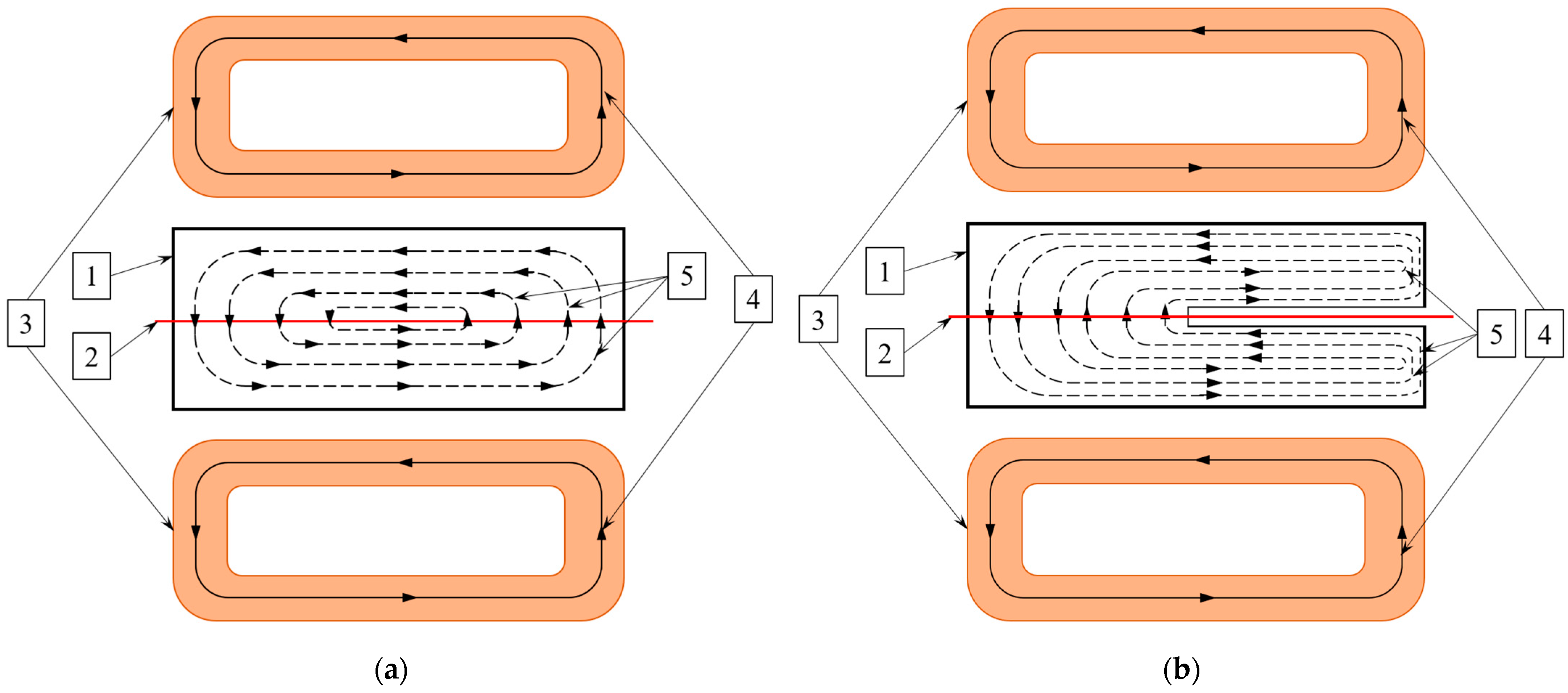
2.1. Idea Description

A tangentially positioned excitation coil created loops of electrical currents in the TO material, the planes of which were perpendicular to the coil axis. Moreover, the simultaneous use of two tangentially positioned excitation coils, located on opposite sides of the TO and connected in series and in-phase, resulted in the excitation field inducing eddy currents in both the upper and the lower plate of the TO. Thus, the eddy currents of two sources unite into common closed loops that penetrate the defect location plane evenly, as shown in Figure 2. In the absence of defects in the plane, currents flow unimpeded, as shown in Figure 2a. Soldering integrity defects create discontinuities in an electrical conductor, displacing the paths of eddy currents, as shown in Figure 2b. Hence, the distribution of eddy currents changes in the presence of defects and is correlated with the defect size, which can be detected and measured using eddy current methods.
As a result, the use of a tangentially located excitation coil creates eddy currents in the TO, which have a non-zero spatial component perpendicular to the plane in which the defects of the soldered lap joints are expected to develop. This spatial component of eddy currents confers sensitivity to the ECP, with coils positioned tangentially to the defects located in the plane parallel to the installation plane of the ECP.

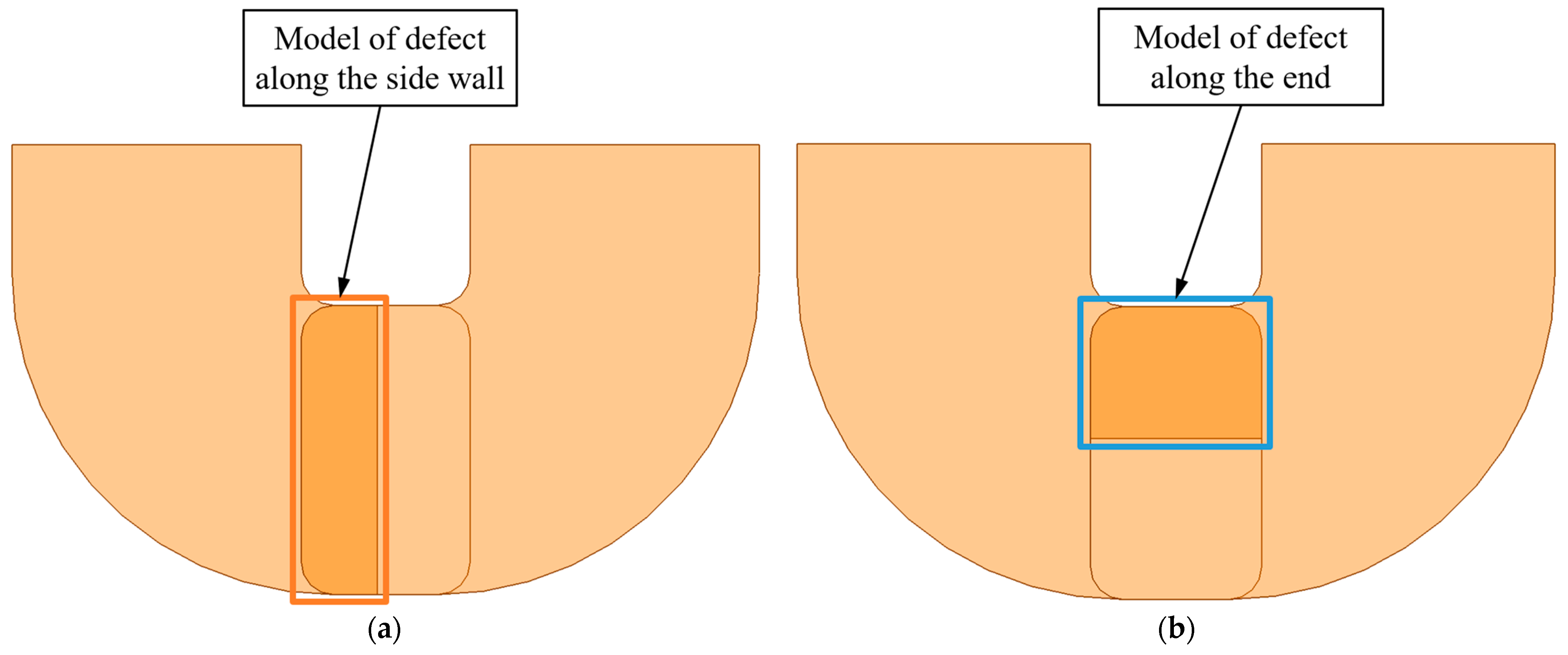
2.2. Description of Problems in Eddy Current Testing of Soldered Lap Joints

In the process of testing the TO using eddy current methods, a range of various stray parameters had a significant influence on the results of the probe measurements.
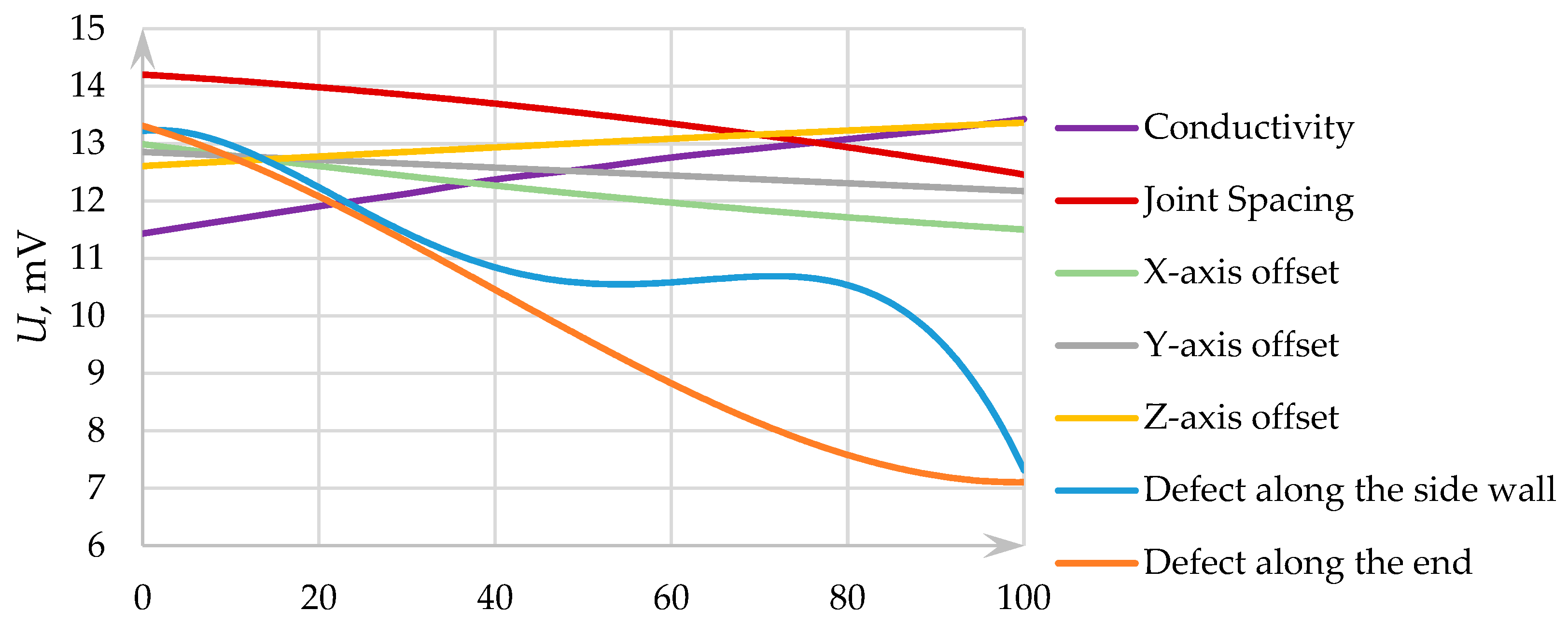
  • The mutual arrangement and relative offset of the ECP and TO: the dimensions of the ECP and TO are comparable, so the displacement of the ECP relative to the TO in any of the X, Y, and Z axes noticeably impacts the ECP signal.
  • The geometric parameters of the TO: The technological tolerance for the thickness of the tested copper busbars is 1 mm, respectively, and the tolerance for the thickness of the soldered joint is ±2 mm. The measurement results of such joints are affected not only by the thickness of the conductive material in the TO but also by the gap between the TO and the installation plane of the ECP, exponentially reducing the penetration depth of eddy currents. Therefore, the existing geometrical tolerances of the TO impose significant limitations on the probe design [33].
  • Adjacent solder joints: In the frontal part of the stator winding of electrical machines, the spacing of the tested joints is dense. When one joint is tested, adjacent copper busbars affect the excitation electromagnetic field, resulting in distorted ECP readings [34,35].
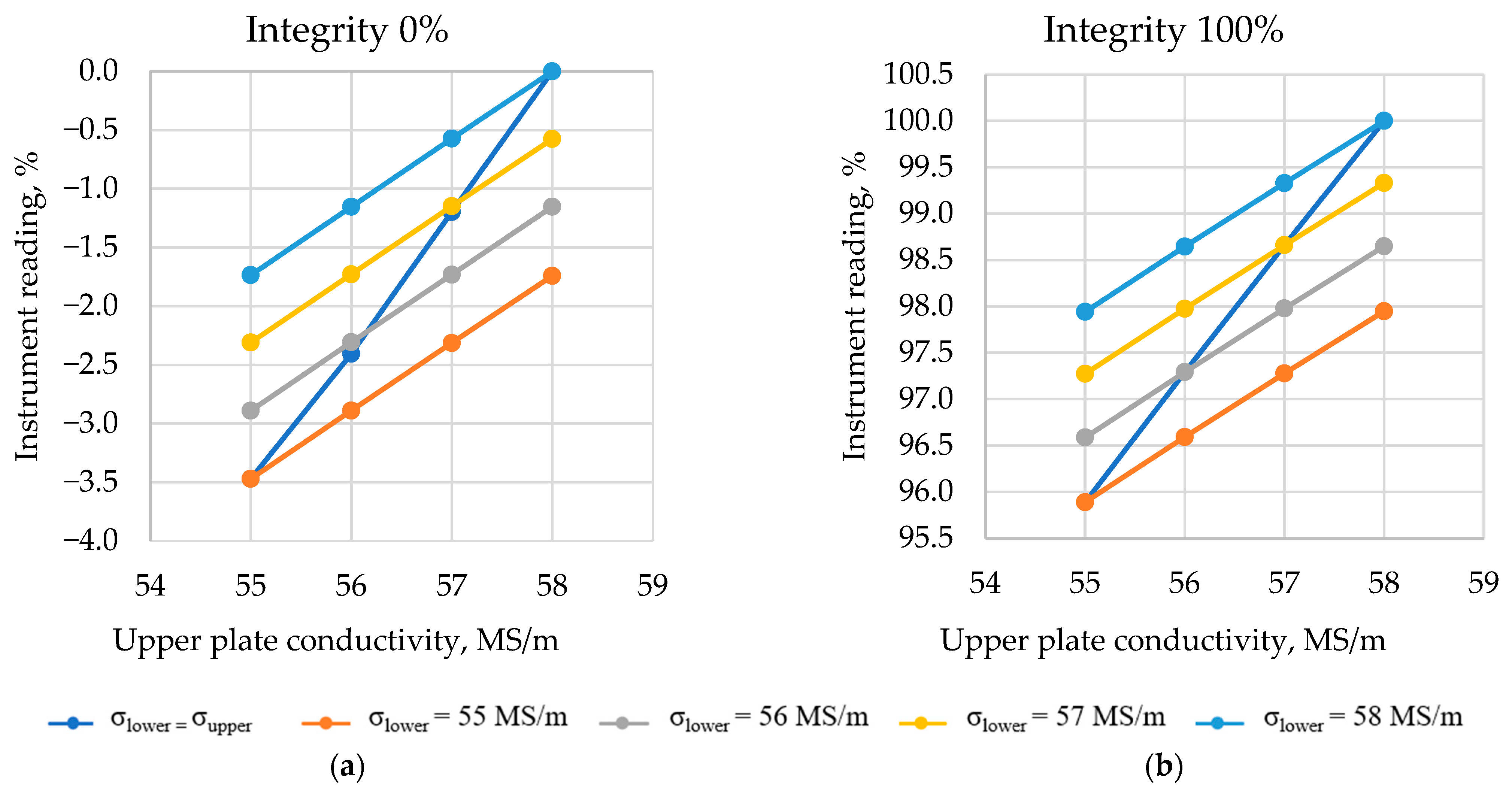
  • The electromagnetic parameters of the TO material: ECP signals are sensitive to variations in the electrical conductivity of the TO material. Therefore, a difference in the values of electrical conductivity for the upper and lower copper plates of the TO distorts ECP measurements. The variation in electrical conductivity in the considered application can be caused mainly for two reasons: a technological variation in the electrical conductivity of the upper and lower plates of the TO and temperature changes affecting the electrical conductivity value of the TO metal [36,37,38].

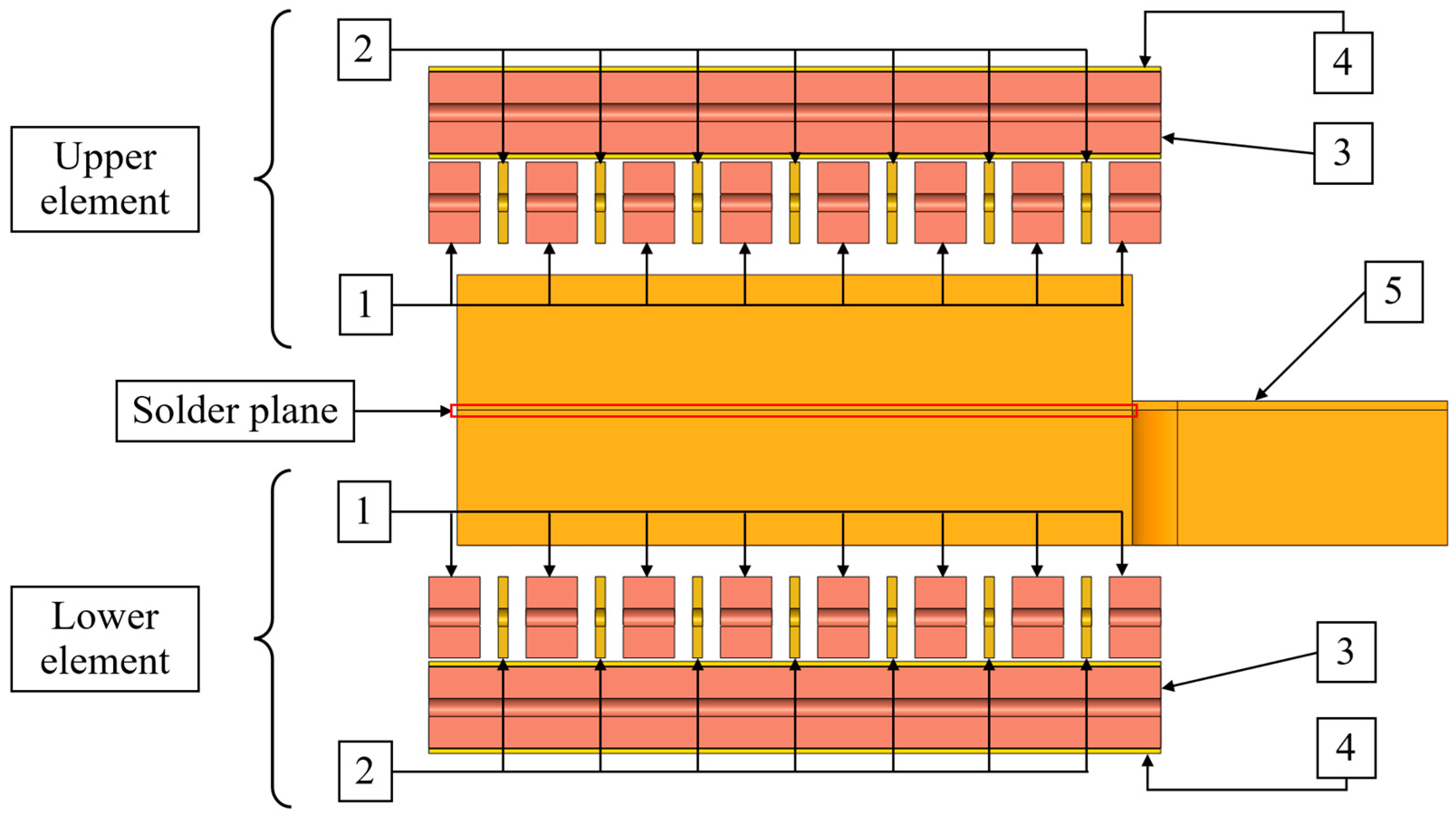
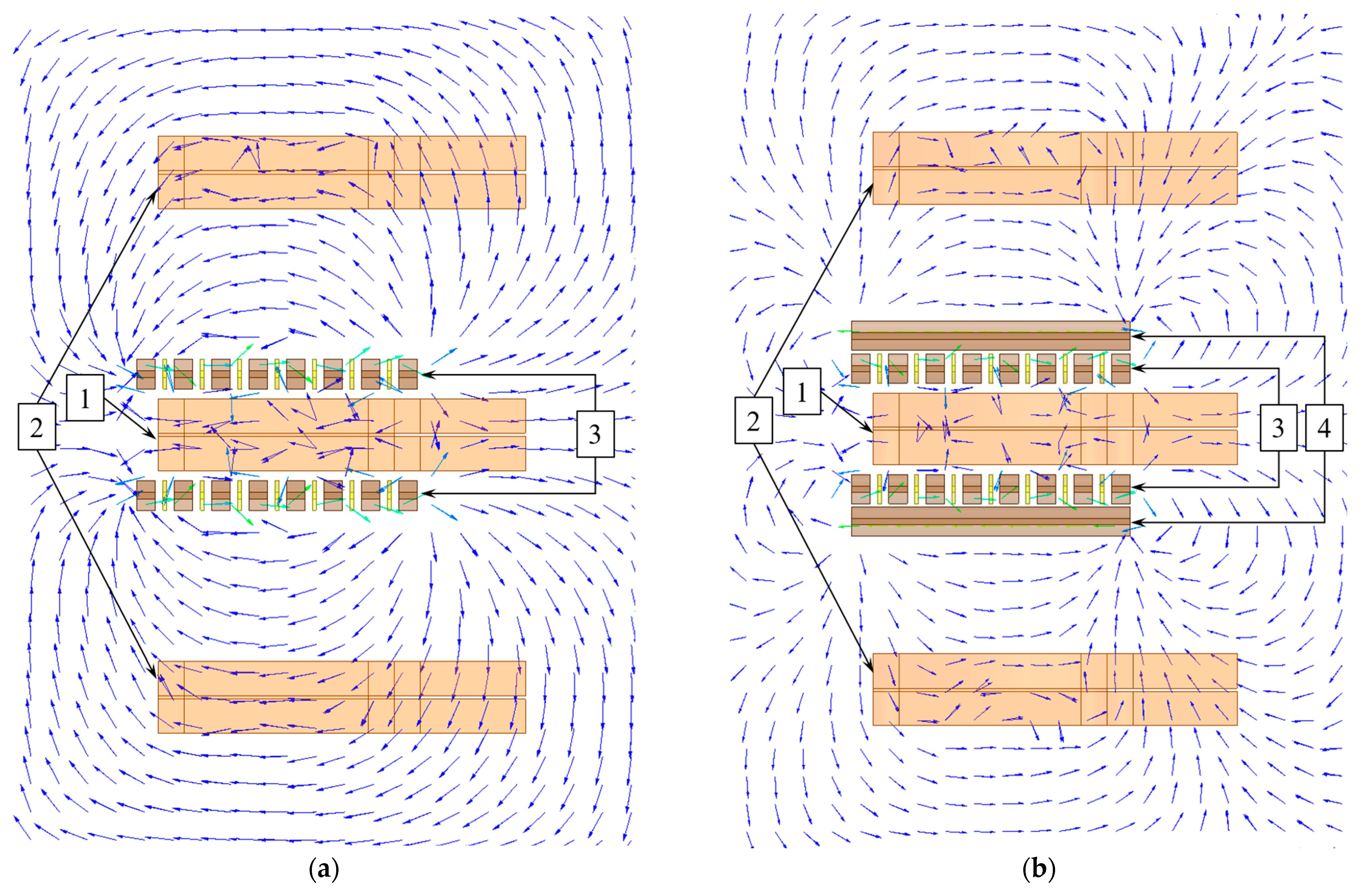
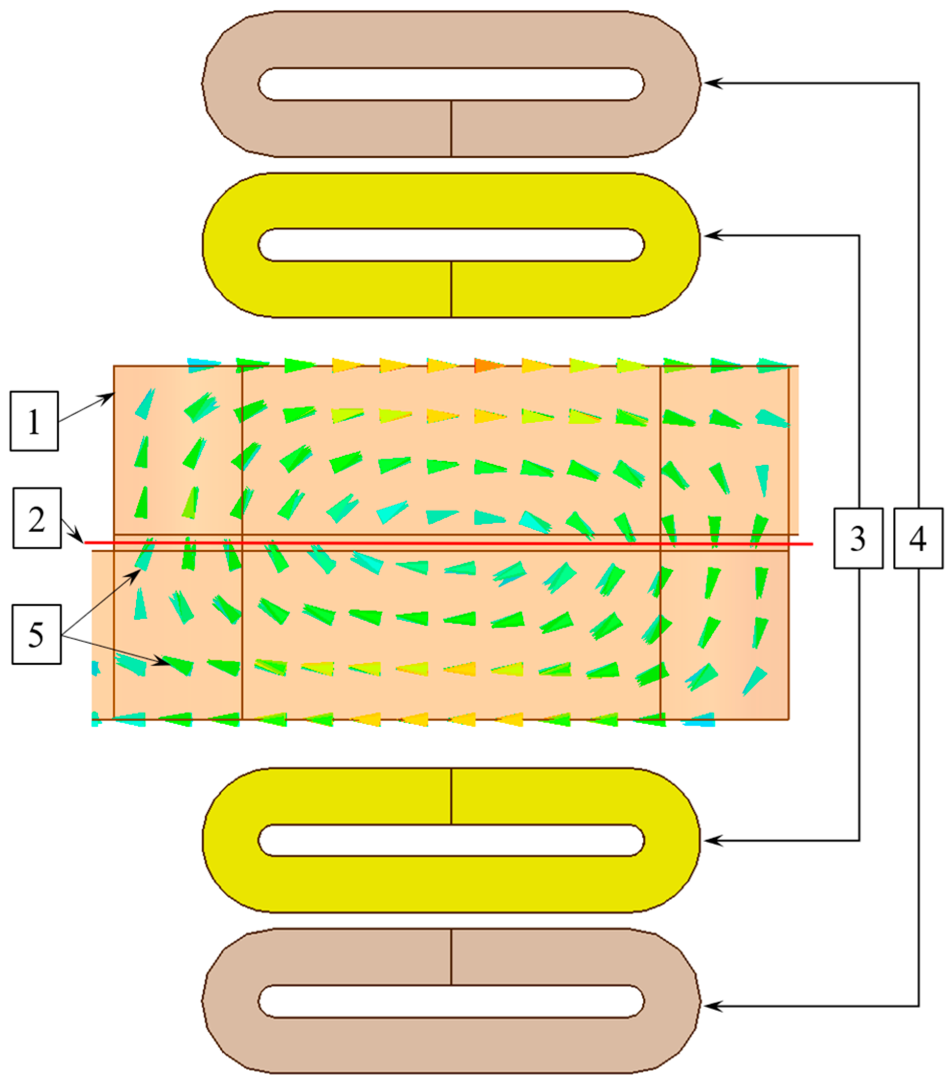
2.3. Finite Element Model of ECP and TO Interaction

Designing the ECP is generally conducted using different methods: analytical calculation and modeling by the finite difference method and finite element method, each of which has its own features [39,40,41]. In order to obtain a precise model of the ECP and TO interaction, the finite element method (FE) was chosen to calculate the parameters of the sensor for testing solder joints [42].
The model of the TO is a horizontally located soldered lap joint of two plates. The overlapping area of the two plates is the tested zone. The test parameter is the soldering integrity of the joint, expressed as the ratio of the actual area of electrical contact between the plates to the overlapping area of the plates. The expected defect is dry solder in the tested zone, whereas both the size and position of the defect within the tested zone are important. For this reason, two types of defects are considered: a defect along the side wall (Figure 3a) and a defect along the end (Figure 3b) [4].
Based on the presented idea, an ECP for testing the soldered lap joints was designed, consisting of two elements located on different sides of the TO symmetrically relative to solder plane (Figure 4). Each element includes four main tangentially positioned coils: excitation, measuring, shielding, and compensation coils.
The electrical circuit of the ECP is shown in Figure 5. The excitation signal in a sine waveform goes from the outputs of the digital-to-analog converter to the amplifiers of the circuit, with the excitation coils and shielding coils connected in series. In the circuit, the measuring coils and compensation coils connected in series are connected to the measuring signal amplifier.
The synchronous detector receives a signal from the measuring signal amplifier and the phase-shifting circuit, in which, by shifting the phase of the excitation signal by −45° and +45°, a reference signal is formed. In the synchronous detector, real and imaginary components extracted from the measurement signal pass through low-pass filters for the removal of harmonics at the excitation frequency. The amplitude values of the filtered real and imaginary components of the measurement signal are fed to the microcontroller via analog-to-digital converters.
The excitation winding consists of 8 coils connected in series. Between the excitation coils are gaps designed to generate magnetic flux leakage, which, penetrating the test object, induces eddy currents in it. Without these gaps, the magnetic field of the excitation and shielding coils would mostly penetrate the coils themselves, similar to how the magnetic field inside a toroidal coil does not extend beyond its dimensions. In the gaps between the excitation coils and coaxially to them are placed 7 measuring coils connected in series. Compensation coils are wound on top of the shielding coils to separate the informative parameter of the ECP signal on the TO from the ECP signal in the air.
To solve the problem of shielding from the influence of adjacent current-carrying busbars on ECP measurement results, the classical method of coil shielding using a ferromagnetic shield is not applicable because coils are positioned tangentially relative to the installation plane of the ECP. Shielding is achieved by using additional shielding coils located on the outer sides of the ECP. In each element of the ECP, a shielding coil is placed above an array of excitation and measuring coils and is connected inversely to excitation coils.
Excitation coils create tangential magnetic field, inducing eddy currents in the TO. Measuring coils perceive the magnetic fields of excitation coils and eddy currents in the TO. When operating an ECP without active shielding, the magnetic field induction lines of the excitation coils penetrate the adjacent joints (Figure 6a). Once active shielding coils are installed, the direction of the magnetic field induction lines penetrating the adjacent joints is reversed (Figure 6b). This indicates the effect of the displacing field of shielding coils. Due to this, a counter magnetic field is created on the outside of the ECP element, distorting the excitation magnetic field, which provides a reduction in the influence of adjacent joints on the testing results.
Serially connected excitation coils form a combined excitation magnetic field to induce eddy currents in the TO. In the gap between excitation coils and measuring coils, magnetic flux leakage is produced, which forms the tangential component of the eddy currents in the TO. This makes it possible to weaken the unchanging component of the magnetic field of excitation coils, increasing the relative amplitude of the signals produced by the eddy currents’ magnetic field as a result. When excitation coils are located both below and above the TO and connected in-phase, a combined eddy current loop is formed, which crosses the plane of defect occurrence almost perpendicularly and homogeneously over its entire zone.
The design and optimization of the FE model of ECP and TO interaction, as well as the process conducted to ensure precision in the calculations, are discussed in detail in a previous study [4]. As a result, a precise model was obtained that confirms the hypothesis of eddy currents passing perpendicular to the defect occurrence plane in a soldered lap joint when tested with a two-element tangential ECP (Figure 7). The signal of the ECP is the voltage U on the measuring coils of the ECP, and the test parameter is the amplitude of the voltage U. Based on this model, the influence of the following parameters on the ECP signal was studied:
  • Test parameters:
    • The size of the defect located along the side wall of the TO (Figure 3);
    • The size of the defect located along the end of the TO (Figure 3).
  • Stray parameters, the deviation ranges of which are given in Table 1:
    • Variation in the electrical conductivity of the TO material;
    • Variation in the distance between adjacent TOs (Figure 8);
    • Displacements of the ECP relative to the TO along the X, Y, and Z axes (Figure 8).
The obtained correlations of the ECP signal with the studied parameters are shown in Figure 9.
Based on the form of ECP signal dependence on defect size along the side wall and along the end, we observe that in the range of defect sizes from 0% to 40%, the ECP signal is almost identical for both defect types. The screening threshold of the TO is 60% soldering integrity; i.e., the allowable size of the defect must not exceed 40%. Building upon this, henceforth, instead of using two types of defects, we shall analyze only the “defect along the end”, whose correlation form is close to a straight line. This will reduce the labor intensity of testing the quality of soldered lap joints by reducing the number of test and reference blocks, and simpler models can be designed to suppress the stray parameters.
The value of the ECP signal deviation caused by the stray parameters is comparable to the value of the ECP signal range from the test parameter. The following means have been implemented to suppress the influence of stray parameters during the testing of soldered lap joints:
  • The suppression of the influence of the TO material’s electrical conductivity is provided by adjusting the measurement results based on the electrical conductivity of the upper and lower plates of the TO. The details of this procedure are given in the next section.
  • A reduction in the influence of the relative orientation of the ECP and TO is provided by probe design features based on calculations of the geometry and required stiffness for fixing the probe position relative to the TO [4].
The developed ECP (Figure 10a) consists of a fixed and a movable plank, inside of which coils for the upper and lower ECP elements are installed. The distance between the movable and fixed planks is secured by a clamp and an anti-backlash junction. The allowable change in distance between the planks is sufficient to compensate for the entire permitted range of thickness deviation for the lap joints. On the fixed plank, a block stop is installed, the position of which is secured by a clamp. This block stop ensures the consistent positioning of the ECP relative to the reference blocks during setup (Figure 10b) and relative to the TO’s end during measurements [4].

2.4. Development of Means of Metrological Assurance for Measuring the Soldering Integrity

The design documentation for copper busbars states the use of copper grade M1 (Cu-ETP) [43] and does not specify the use and testing of electrical grade copper, for which electrical conductivity is standardized. Taking into account the quality of incoming products, an inadmissible variation in the electrical conductivity of copper busbars in a single electrical machine is expected. At the same time, as previously stated, electrical conductivity (relative or specific) is a significant stray parameter when testing is procured using the developed ECP. Therefore, the testing procedure requires the adjustment of probe measurements using a correction factor based on the value of the electrical conductivity of the TO.
In order to compensate for the variation in electrical conductivity, a methodology for suppressing the influence of electrical conductivity on the measurement results was developed. Electrical conductivity measurement in the process of measuring the soldering integrity was performed using a conductivity meter, “Konstanta K6”, with a PF-IE-6e-Cu probe (LLC “Konstanta”, Saint-Petersburg, Russia), providing a measurement range of 25 to 59 MS/m and a standard permissible error limit of 3%.
In order to verify performance and calibrate the conductivity meter, a set of SO-220 electrical conductivity calibration blocks, (LLC “Konstanta”, Saint-Petersburg, Russia) were used. A set includes 3 cylindrical copper group samples with high long-term characteristic stability, with nominal electrical conductivity values of 42, 50, and 58 MS/m.
Metrological assurance in measuring the soldering integrity of soldered lap joints of copper busbars in electrical machines is represented by sets of reference blocks (RBs) (Figure 11). One set includes a monolithic block to simulate 100% soldering integrity and a composite block to simulate 0% soldering integrity, composed of two parts, glued together through a dielectric gasket. RBs are manufactured specifically for each type of busbar for the tested electrical machine from electrical copper, the conductivity of which was tested.
The developed RBs were used to study the correlation between the instrument readings and the different conductivity values of the upper and lower copper busbars in a solder joint with 0% and 100% soldering integrity values. In addition, the instrument readings were obtained from copper busbars, whose plates had different conductivity values (Figure 12).
Based on these correlations, a formula was derived for correcting ECP measurement results, taking into account the deviation in the conductivity of solder joints:
S = k σ T O + σ 0 + σ 100 σ T O σ T O k + R e z ,
k = σ 100 R e z + σ 0 100 R e z 100
where
S—TO soldering integrity, %;
σ0—electrical conductivity of the 0% soldering reference block, MS/m;
σ100—electrical conductivity of the 100% soldering reference block, MS/m;
σTO—arithmetic mean value of conductivity of plates of the solder joint, MS/m;
Rez—instrument reading, %.
Thus, the main principles behind the methodology for suppressing the influence of electrical conductivity on the results from measuring the soldering integrity of soldered lap joints of copper busbars in the stator windings of electrical machines are as follows:
  • Testing conditions: Testing is carried out at least 3 h after soldering the copper busbars of the turbine generator. The RBs should be kept together with the TO for at least 1 h.
  • Before soldering testing, the conductivity meter is calibrated with conductivity calibration blocks.
  • The conductivity values of the 0% and 100% RBs are measured.
  • The electrical conductivity values of the upper and lower plates of the solder joint are measured, and the arithmetic mean value of the electrical conductivity of the solder joint is calculated from the two values and then recorded in the protocol.
  • A suitable probe is connected to the instrument; zero setting is performed in air; and 0% and 100% are set for the respective RBs without setting the screening threshold level.
  • The soldering integrity of each joint is measured. The measurement results are recorded in the protocol.
  • The protocol data are compared, and the actual value of the soldering integrity of each solder joint is calculated using Formula (1).
  • In accordance with the screening threshold defined earlier, a list of defective joints and joints with suspected defects is compiled.
  • The re-testing of joints with suspected defects is performed, and their defectiveness/non-defectiveness is confirmed.

3. Results

3.1. Development and Testing of the ECP Operational Prototype

The developed ECP is produced with three modifications to cover all types of soldered joints of busbars for tested electrical machines, the parameters of which are given in Table 2. Allowed TO materials are non-ferromagnetic metals with an electrical conductivity of no less than 15 MS/m. The measurement range of soldering integrity is from 0 to 100%. The standard permissible error limit for soldering integrity is 5%. The variation range for the total gap between the probe coils and the TO surface allowed during testing is from 0 to 10 mm.
The developed eddy current probe for testing the soldering integrity of soldered lap joints is used in a set with an eddy current flaw detector, “Konstanta VD-1” (LLC. “Konstanta”, Saint-Petersburg, Russia), and this allows for the detection of unsoldered joints and voids, as well as measuring the soldering integrity of soldered lap joints for copper busbars.

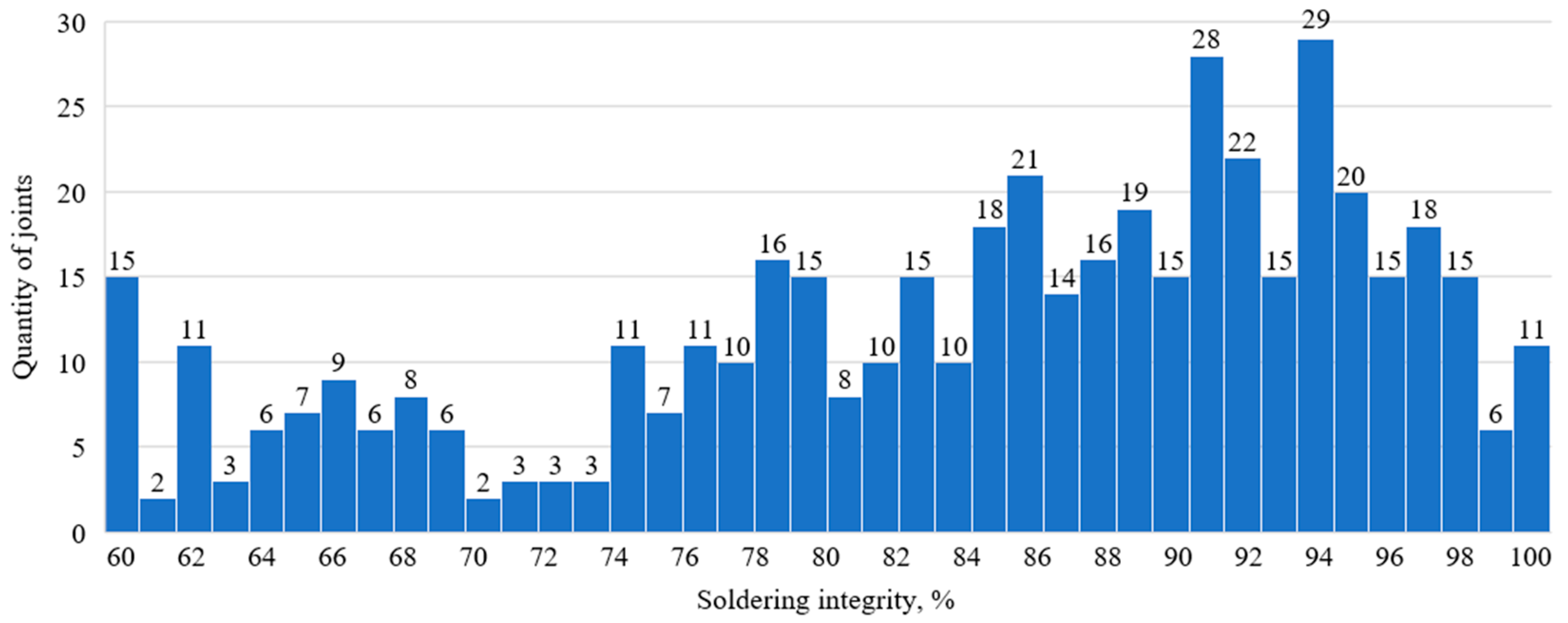
3.2. On-Site Testing

As a result of the on-site testing of soldered joints in the stator winding of a TVF-60-2 turbine generator, the performance of the developed ECP was demonstrated to assess the quality of the stator winding joints by measuring the actual value of the soldering integrity of the soldered lap joints. The statistics of the measurements are shown in Figure 13. The screening threshold is established in the technological instructions for the eddy current testing of soldered joints in the stator windings of turbine and hydro-generator stators. The value for the internal defects of the soldered joints in the form of discontinuities should not exceed 40%. Consequently, the quality of soldering is characterized by the value of soldering integrity and should be no less than 60%. Thus, based on the measurement results, the value for soldering internal defects in stator winding joints does not exceed the screening threshold; hence, the quality of soldering in stator winding busbar joints complies with the requirements of the technological instructions.
The on-site testing results display the applicability of the designed ECP to evaluate the soldering integrity of soldered lap joints in current-carrying busbars for stator winding electrical machines. Compared to the existing approach for unsoldered lap joint detection based on thermal inspection, the developed method provides a more safe and precise technique, allowing for not only the detection of but also the evaluation of the soldering quality of soldered lap joints. The developed technical method provides the following:
-
Suppression of the influence of electrical conductivity, temperature, and technological variations in the geometry of the tested zone for both the TO and RBs;
-
The required reliability in the measurement results without strict requirements regarding the deviation in the electromagnetic and geometrical parameters of the TO and RB from their nominal values;
-
The detection of defects and the measurement of the degree of soldering integrity in the soldered lap joints with a relative error of measurement of no more than 5%.

4. Discussions

The novel concept of the application of a two-element eddy current probe with tangentially positioned coils for the non-destructive testing of soldered lap joints has been presented. The design of a two-element eddy current probe with tangentially positioned coils and active shielding was developed. A method for determining the soldering integrity of soldered lap joints of current-carrying copper busbars in the stator windings of electrical machines through the developed probe was suggested. The proposed method ensures the detection of dry solder and cold solder joints and the measurement of the soldering integrity of the soldered lap joints with a relative error of measurement of no more than 5%.
The proposed method of designing and optimizing the parameters of the finite element model can be used in the development of low-frequency eddy current probes with various designs and to study the influence of stray parameters encountered in practice, which cannot be reliably reproduced in real test objects or reference blocks.
The developed finite element model of the ECP and TO interaction allows the influence of the test and stray parameters on the ECP signals to be studied for the testing of soldered lap joints of current-carrying busbars in electrical machine windings. The convergence of the measurement results from the finite element model of an ECP and from a real ECP was confirmed with the help of an operational prototype of an ECP. The error in the calculations of the signals from the ECP finite element model does not exceed 1.5%.

Author Contributions

Conceptualization, P.S.; methodology, V.S. and A.U.; software, A.G. and P.S.; validation, A.G. and P.S.; formal analysis, P.S. and A.U.; investigation, A.G. and P.S.; resources, A.G.; data curation, V.S.; writing—original draft preparation, A.G.; writing—review and editing, V.S. and A.U.; visualization, A.G.; supervision, V.S. and A.U.; project administration, V.S.; funding acquisition, V.S. All authors have read and agreed to the published version of the manuscript.

Funding

This research received no external funding.

Institutional Review Board Statement

Not applicable.

Informed Consent Statement

Not applicable.

Data Availability Statement

The original contributions presented in the study are included in the article, further inquiries can be directed to the corresponding author.

Conflicts of Interest

Authors Vladimir Syasko, Pavel Solomenchuk were employed by the company LLC “KONSTANTA”. The remaining authors declare that the research was conducted in the absence of any commercial or financial relation-ships that could be construed as a potential conflict of interest.

Correction Statement

This article has been republished with a minor correction to the readability of figure 2. This change does not affect the scientific content of the article.

References

  1. Klempner, G.; Kerszenbaum, I. Maintenance. In Handbook of Large Turbo Generator Operation and Maintenance, 2nd ed.; Klempner, G., Kerszenbaum, I., Eds.; Wiley-IEEE Press: Piscataway, NJ, USA, 2008; pp. 923–974. [Google Scholar] [CrossRef]
  2. Andreev, D.A.; Nazarychev, A.N.; Folvarchuk, A.S. Justification of the Prospects for Selecting the Main Electrical Equipment in the Generator Circuit of High-Power Nuclear Power Plant Units. Power Technol. Eng. 2023, 57, 438–444. [Google Scholar] [CrossRef]
  3. ISO 1190-1:1982; Copper and Copper Alloys-Code of Designation—Part 1 Designation of Materials. International Standard Organization: Geneva, Switzerland, 1982.
  4. Gorbunov, A.E.; Solomenchuk, P.V.; Umanskii, A.S. Modeling a Two-Element Tangential Eddy Current Probe with Active Shielding for Soldered Joint Testing. Russ. J. Nondestruct. Test. 2024, 60, 912–920. [Google Scholar] [CrossRef]
  5. GOST R 56542-2019; Non-Destructive Testing. Classification of Types and Methods. Federal Agency for Technical Regulation and Metrology: Moscow, Russia, 2019.
  6. Olenev, L.A.; Zakieva, R.R.; Smirnova, N.N.; Shichiyakh, R.A.; Ershov, K.A.; Geetha, N. Accurate composition dependent thermo mechanical lifetime estimation of hour glass type solder joint in electronic assemblies. Solder. Surf. Mt. Technol. 2022, 34, 8–15. [Google Scholar] [CrossRef]
  7. Andreev, D.A.; Nazarychev, A.N.; Folvarchuk, A.S. Methods for Reducing Short-Circuit Currents in the Generator Circuit When Designing High-Power Units in Nuclear Power Plants. Power Technol. Eng. 2023, 56, 711–717. [Google Scholar] [CrossRef]
  8. ISO 15549:2019; Non-Destructive Testing—Eddy Current Testing—General Principles. International Standard Organization: Geneva, Switzerland, 2019.
  9. Muratov, K.R.; Gashev, E.A.; Ablyaz, T.R.; Maksimov, P.V.; Permyakov, M.S.; Lekomtsev, A.V.; Ilyushin, P.Y.; Korobov, G.Y. Determining the Actual Contact Area in Mutual Lapping of Surfaces. Russ. Engin. Res. 2021, 41, 437–438. [Google Scholar] [CrossRef]
  10. Mustafaev, A.S.; Sukhomlinov, V.S.; Bazhin, V.Y.; Bukovetskiy, N.A.; Surov, A.V. Plasma technology for producing ultrapure corundum. Tsvetnye Met. 2024, 4, 21–29. [Google Scholar] [CrossRef]
  11. Gromyka, D.S.; Gogolinskiy, K.V. Method of State and Residual Resource Assessment of Excavator Bucket Tooth Caps. Russ. J. Nondestruct. Test. 2022, 58, 381–390. [Google Scholar] [CrossRef]
  12. Potapov, A.I.; Syasko, V.A. Non-Destructive Methods and Means of Coating Thickness and Products Testing. Scientific, Guidance, Reference Manual Methodic; Gumanistika: Saint-Petersburg, Russia, 2009; Volume 1, p. 904. (In Russian) [Google Scholar]
  13. Syasko, V.A.; Roitgarts, M.B.; Koroteev, M.Y.; Solomenchuk, P.V. Quality control of soldered joints of the rods of stator windings of turbogenerators on “Elektrosila” plant. V Mire Nerazrush. Kontrolya 2010, 2, 40–43. [Google Scholar]
  14. Potapov, A.I.; Syasko, V.A.; Koroteev, M.Y.; Solomenchuk, P.V. A Finite-element modeling of a probe of eddy-current quality testing of soldered joints in turbogenerator windings. Russ. J. Nondestruct. Test. 2014, 50, 264–273. [Google Scholar] [CrossRef]
  15. Koroteev, M.Y. Calculation of eddy current probe parameters for quality control of turbine generators rods winding soldering. Estestvennye i Tekhnicheskie Nauki 2014, 2, 195–204. (In Russian) [Google Scholar]
  16. Koroteev, M.Y. Eddy Current Quality Control of Soldered Joints of Stator Winding of Turbo Generators. Thesis for the degree of Candidate of Sciences in Technology, National Mineral Resource University (University of Mines), Saint-Petersburg, Russia, 2014. [Google Scholar]
  17. Potapov, A.I.; Syasko, V.A.; Koroteev, M.Y.; Solomenchuk, P.V. Method to Assess Quality of Soldered Joint in Windings of Electric Machines. RF Patent No. 2572791C2, 20 January 2016. [Google Scholar]
  18. Fashchuk, V.I. Device for Quality Monitoring of Soldered Connection of Windings of Electrical Machines. RF Patent No. 2704011, 23 October 2019. [Google Scholar]
  19. Kogan, L.; Nichipuruk, A.; Savary, F.; Principe, R.; Datskov, V.; Rozenfel’d, E.; Khudjakov, B. Eddy current quality of soldered current-carrying bas-bar splices of superconducting magnets. Insight 2015, 57, 697. [Google Scholar] [CrossRef]
  20. Kogan, L.K.; Nichipuruk, A.P.; Rosenfel’d, E.V.; Khudyakov, B.A. A Method for Nondestructive Quality Assurance of Soldering in Current-Carrying Joints. RF Patent No. 2567736, 10 November 2015. [Google Scholar]
  21. Kogan, L.K.; Stashkov, A.N.; Nichipuruk, A.P. Improving the Reliability of Eddy-Current Quality Control of Soldering in Current-Carrying Copper Joints and Expanding the Nomenclature of Inspected Joints in Energy Equipment. Russ. J. Nondestruct. Test. 2018, 54, 784–791. [Google Scholar] [CrossRef]
  22. Kogan, L.K.; Stashkov, A.N.; Nichipuruk, A.P. Eddy Current Quality Control of Soldering in Superconducting Current-Carrying Joints with Allowance for the Effect of Cross Section Variations on Testing Results. Russ. J. Nondestruct. Test. 2019, 55, 654–662. [Google Scholar] [CrossRef]
  23. Kogan, L.H.; Stashkov, A.N. Method for Eddy Current Quality Control of Soldering Joints of Current-Carrying Bars of Superconducting Electromagnets. RF Patent No. 2726910, 16 July 2020. [Google Scholar]
  24. Kogan, L.K.; Stashkov, A.N. Capabilities of Eddy Current NDT of Soldered Current-Carrying Joints in Submersible Electrical Equipment for Oil and Gas Industry. Diagn. Resour. Mech. Mater. Struct. 2023, 4, 47–59. [Google Scholar] [CrossRef]
  25. Koyama, K.; Hoshikawa, H.; Hirano, T. Investigation of impact damage carbon fiber reinforced plastic (CEPR) by eddy current non-destructive testing. In Proceedings of the International Conference NDT, Montreal, QC, Canada, 4 November 2011. [Google Scholar]
  26. Mizukami, K.; Mizutani, Y.; Kimura, K.; Sato, A.; Todoroki, A.; Suzuki, Y. Detection of in-plane fiber waviness in cross-ply CFRP laminates using layer selectable eddy current method. Compos. Part A Appl. Sci. Manuf. 2016, 82, 108–118. [Google Scholar] [CrossRef]
  27. Syas’ko, V.A.; Chertov, D.N. Detection of delaminations in carbon composite materials using tangential eddy-current sensors. V Mire NK 2012, 2, 19–21. (In Russian) [Google Scholar]
  28. Shkatov, P.N.; Didin, G.A.; Ermolaev, A.A. Advanced Eddy Current Transducer for Non-Destructive Inspection of CFRP Materials. In Proceedings of the Russian STC with International Participation “Innovative Technologies in Electronics and Instrumentation (“RNTK FTI—2020”) “, Physics and Technology Institute RTU MIREA, Moscow, Russia, 16 April 2020. (In Russian). [Google Scholar]
  29. Shkatov, P.N.; Didin, G.A. Eddy Current Transducer for Quality Control of CFRP Objects. RF Patent No. 2733942C1, 8 October 2020. [Google Scholar]
  30. Huang, R.; Lu, M.; Chen, Z.; Yin, W. Reduction of Coil-Crack Angle Sensitivity Effect Using a Novel Flux Feature of ACFM Technique. Sensors 2022, 22, 201. [Google Scholar] [CrossRef] [PubMed]
  31. Shkatov, P.N. Eddy Current Converter for Flaw Detection. RF Patent No. 2796194C1, 17 May 2022. [Google Scholar]
  32. Shkatov, P.N. Eddy Current Transducer for Flaw Detection. RF Patent No. 2813477C1, 12 February 2024. [Google Scholar]
  33. Gonchar, A.V.; Klyushnikov, V.A.; Mishakin, V.V.; Anosov, M.S. Ultrasonic and eddy-current fatigue monitoring of austenitic steel welded joints. Russ. J. Nondestruct. Test. 2021, 57, 570–578. [Google Scholar] [CrossRef]
  34. Syasko, V.; Musikhin, A.; Gnivush, I. Improvement of Methods and Devices for Multi-Parameter High-Voltage Testing of Dielectric Coatings. Coatings 2024, 14, 427. [Google Scholar] [CrossRef]
  35. Gromyka, D.S.; Gogolinskiy, K.V. Introduction of Evaluation Procedure of Excavator Bucket Teeth into Maintenance and Repair: Prompts. MIAB Min. Inf. Anal. Bull. 2023, 8, 94–111. [Google Scholar] [CrossRef]
  36. Alekhnovich, V.; Syasko, V.; Umanskii, A. Multi-Parameter Complex Control of Metal Coatings on Ball Plugs of Pipeline Shut-Off Valves. Inventions 2024, 9, 78. [Google Scholar] [CrossRef]
  37. Teterko, A.Y.; Uchanin, V.M.; Hutnyk, V.I. Improvement of the Accuracy of Eddy-Current Testing of the Electric Conductivity of Materials and the Thickness of Dielectric Coatings of the Shells. Mater. Sci. 2014, 49, 857–865. [Google Scholar] [CrossRef]
  38. Gendler, S.G.; Kryukova, M.S.; Alferova, E.L. Investigation of thermodynamic parameters of the air environment in subway lines with single-track and double-track tunnels. Min. Sci. Technol. 2024, 9, 250–262. [Google Scholar] [CrossRef]
  39. Lehikoinen, A.; Arkkio, A.; Belahcen, A. Reduced Basis Finite Element Modeling of Electrical Machines with Multiconductor Windings. IEEE Trans. Ind. Appl. 2017, 53, 4252–4259. [Google Scholar] [CrossRef]
  40. Gogolinsky, K.V.; Ivkin, A.E.; Alekhnovich, V.V.; Vasiliev, A.Y.; Tyurnina, A.E.; Vasiliev, A.S. Evaluation of the accuracy indicators in determination of the coating thickness by crater grinding method. Industrial laboratory. Diagn. Mater. 2020, 86, 39–44. (In Russian) [Google Scholar] [CrossRef]
  41. Mustafaev, A.S.; Grabovskiy, A.Y.; Sukhomlinov, V.S.; Shtoda, E.V. Technology for monitoring the surface emission inhomogeneity in plasma electronics devices. J. Appl. Phys. 2024, 20, 203303. [Google Scholar] [CrossRef]
  42. JCGM 200:2008; International Vocabulary of Metrology—Basic and General Concepts and Associated Terms (VIM3). Joint Committee for Guides in Metrology: Sevres, France, 2008.
  43. DIN EN 1652-1998; Copper and Copper Alloys—Plate, Sheet, Strip and Circles for General Purposes. German Institute for Standardization: Berlin, Germany, 1998.
Figure 1. Solder joint of copper busbars: (a) photograph of TO in stator winding; (b) drawing of TO [4].
Applsci 15 02036 g001
Figure 2. Vector field of propagation of eddy currents in two-element tangential ECP in (a) TO without defects and (b) TO with defects: 1—TO; 2—defect location plane; 3—tangentially placed ECP coils; 4—current direction in ECP coils; 5—eddy current propagation lines in TO.
Applsci 15 02036 g002
Figure 3. Models of defect simulators: (a)—TO with a model of a soldering defect along the side wall; (b)—TO with a model of a soldering defect along the end.
Applsci 15 02036 g003
Figure 4. Close-up of ECP coils and TO: 1—excitation coils; 2—measuring coils; 3—shielding coils; 4—compensation coils; 5—TO [4].
Applsci 15 02036 g004
Figure 5. Electrical schematic diagram of ECP [4].
Applsci 15 02036 g005
Figure 6. Magnetic field pattern of the finite element model of an ECP (a) without shielding coils and (b) with shielding coils: 1—TO; 2—adjacent solder joints; 3—excitation coils; 4—shielding coils.
Applsci 15 02036 g006
Figure 7. Pattern of eddy current lines in the finite element model of the TO: 1—TO; 2—plane of soldered lap joint; 3—excitation coils; 4—shielding coils; 5—eddy current lines.
Applsci 15 02036 g007
Figure 8. Model of ECP, TO, and adjacent solder joints: 1—TO; 2—upper element of ECP; 3—lower element of ECP; 4—upper solder joint; 5—lower solder joint.
Applsci 15 02036 g008
Figure 9. Correlations of ECP model signal with deviations in studied parameters.
Applsci 15 02036 g009
Figure 10. Photographs of the developed ECP: (a)—ECP design; (b)—ECP installation on RB [4].
Applsci 15 02036 g010
Figure 11. Reference blocks of soldered lap joints: 1—RB of 100% soldering integrity; 2—RB of 0% soldering integrity.
Applsci 15 02036 g011
Figure 12. Correlation between the instrument readings and the electrical conductivity of the TO: (a) correlation for TO with 0% soldering integrity; (b) correlation for TO with 100% soldering integrity.
Applsci 15 02036 g012
Figure 13. Statistics of measurements of soldering integrity of soldered lap joints in TVF-60-2 turbine generator.
Applsci 15 02036 g013
Table 1. Deviation ranges of stray parameters.
Parameter0%100%Units
Electrical conductivity4060MS/m
Joint spacing7090mm
X-axis offset010mm
Y-axis offset010mm
Z-axis offset03mm
Table 2. Parameters of ECP versions.
ParameterPP-37PP-42PP-58
Minimum TO thickness, mm12.51420
Maximum TO thickness, mm3131.544.5
Minimum TO length, mm303030
Maximum length of TO tested zone, mm96105105
Minimum TO width, mm303138
Maximum width of TO tested zone, mm576278
Range for setting the distance between the probe planks, mm22.5–3224–3330–45.5
Frequency of excitation current, Hz12012075
Disclaimer/Publisher’s Note: The statements, opinions and data contained in all publications are solely those of the individual author(s) and contributor(s) and not of MDPI and/or the editor(s). MDPI and/or the editor(s) disclaim responsibility for any injury to people or property resulting from any ideas, methods, instructions or products referred to in the content.

