Article

Research on the Reciprocating Friction and Installation Force of Seals in Deep-Sea Samplers

1
China Ship Scientific Research Center, Wuxi 214082, China
2
Ocean College, Zhejiang University, Zhoushan 316000, China
3
Qingdao Innovation and Development Base, Harbin Engineering University, Qingdao 266000, China
*
Author to whom correspondence should be addressed.
Appl. Sci. 2025, 15(4), 1867; https://doi.org/10.3390/app15041867
Submission received: 18 December 2024 / Revised: 9 February 2025 / Accepted: 10 February 2025 / Published: 11 February 2025
(This article belongs to the Section Marine Science and Engineering)

Abstract

:
It is crucial to accurately characterize the static and dynamic properties of seals for the design of deep-sea equipment. This study investigated the movement resistance of O-rings under high pressure (up to 30 MPa) and low temperature (2 °C). Numerical simulation models were set up to investigate the effects of material properties and seal structure dimensions on the reciprocating friction and installation force of O-rings. Furthermore, a novel resistance testing rig was developed to facilitate the measurement of reciprocating friction and installation force of O-rings under high pressure and low temperature. The results of this study indicate that nitrile rubber (NBR) has a reduced sensitivity to temperature variations, and the hardening of the material due to the low temperatures encountered in deep-sea environments does not substantially increase its movement resistance. Conversely, fluororubber (FKM) exhibits superior static sealing reliability. We optimized the sealing structure of the pressure-maintaining trapping instrument (PMTI) and successfully conducted field tests at the South China Sea. The results of this study may serve as a valuable reference for the sealing design of deep-sea equipment.

1. Introduction

Deep-sea scientific research and resource exploration depend on a variety of operational equipment, including submersibles, robotic arms, and samplers [1,2,3]. O-ring seals are widely used in deep-sea devices due to the advantages of simplicity, reliability, durability, and cost-effectiveness [4,5]. Rubber becomes harder, stiffer, and less resilient with decreasing temperature of the deep sea [6]. An accurate evaluation of the influence of the deep-sea environment on O-ring friction is essential for seal design and improving the efficiency of deep-sea equipment.
Scholars have conducted extensive research on the friction of O-ring seals through theoretical modeling, numerical simulations, and experimental testing [7,8,9,10]. For O-rings in deep-sea operating conditions, Huang et al. [11] employed polytetrafluoroethylene (PTFE)-coated O-rings in a deep-sea water sampler to minimize the friction of O-rings, and the sampler was successfully deployed at a depth of 3930 m. He et al. [12] studied the static sealing characteristics of combined seals for deep-sea sediment samplers under high pressure by numerical simulation and confirmed the accuracy of the numerical results through pressure-holding experiments. Wu et al. [13] investigated the volumetric shrinkage of O-rings caused by increased ambient pressure and analyzed the static sealing properties of O-rings using finite element analysis (FEA) method. Liu et al. [14] designed a non-standard O-ring sealing structure for ball joints used in deep-sea drilling apparatus and validated the reliability of their design through pressure retention experiments. Sun et al. [15] conducted both simulation and experimental investigations on the extrusion failure of O-rings in deep-sea environments, deriving the critical failure curve of O-rings. Han et al. [16] studied the sealing performance of O-rings in deep-sea wet-mate electrical connectors under a fluid pressure of 30 MPa. The results highlighted that employing a pressure-balanced seal structure can significantly reduce both friction and leakage. Li et al. [17] investigated the factors influencing the sealing performance of submarine electrical connectors. They examined the effects of the friction coefficient, compression rate, and other variables on the distribution of sealing contact pressure under a hydrostatic pressure of 15 MPa. Davies et al. [18] analyzed the aging phenomenon of NBR O-rings used in a 6000 m class deep submersible named Ifremer Nautile after 10 years of operation. They proposed a testing method to predict the long-term sealing performance of these nitrile O-rings.
However, there are relatively few studies in the existing literature regarding the reciprocating friction of seals in ultrahigh-pressure and low-temperature environments. Most research on the sealing characteristics of seals in deep-sea environments has primarily concentrated on the static sealing reliability, while their dynamic friction characteristics have predominantly been investigated through experimental methods. Furthermore, there is a notable gap in the research concerning the installation force of seals. Figure 1 illustrates the source of the practical problem in this study. In a field test at the Mariana Trench, the sampling piston of the full-ocean-depth pressure-retaining amphipod sampler named PMTI (Figure 1a) [19] developed by the research team was not fully retracted into the pressure vessel (Figure 1b). Considering the temperature of the operation site is approximately 2 °C [20]. It is hypothesized that the increase in the modulus of elasticity, hardening, and brittleness of rubber at low temperatures are the primary factors contributing to this failure. O-ring 2 was drawn into the pressure vessel in a manner similar to the installation of a seal, leading to a significant increase in axial movement resistance. As a result, the motor stalled due to excessive load. This malfunction has also been observed in a sediment sampler [21]. Although similar failures have not been observed in some equipment that relies on submersible manipulators for sampling [22,23], this discrepancy can be attributed to the ability of hydraulically powered manipulators to generate adequate force.
In this research, we investigated the reciprocating friction (RF) and installation force (IF) of O-rings fabricated from FKM and NBR, the two most frequently used materials in ocean engineering. Numerical calculation models were developed to analyze the RF and IF of O-rings under high pressure and low temperature. Additionally, we established a test rig to measure the RF and IF of O-rings in high-pressure and low-temperature environments. We optimized the design of the PMTI seal and conducted in situ testing in the South China Sea. This study aims to provide a valuable reference for the seal design of deep-sea equipment.

2. Methods

2.1. Numerical Simulation

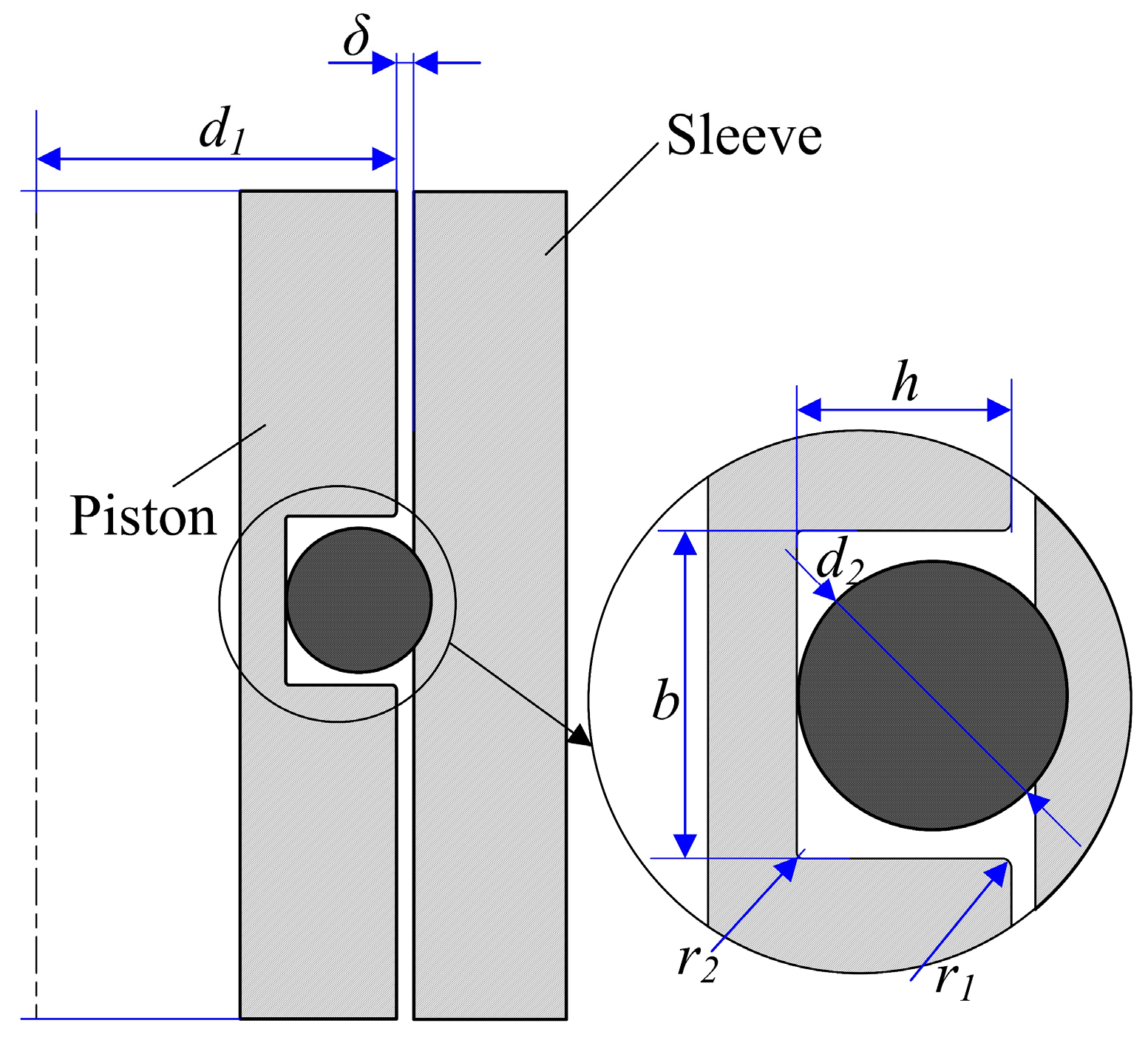
2.1.1. Geometry and Materials

To quantitatively determine the force during the retraction of the sampling piston, the process was simulated using the FEA software Abaqus (Version 2021). The geometric model for the numerical study is shown in Figure 2. The dimensions of the geometric model, which conform to the standards of the Chinese mechanical engineering industry, are detailed in Table 1. Additionally, the results of the study on the static sealing properties of NBR and FKM under high-pressure and low-temperature conditions are presented in Appendix A.
According to industry standards for evaluating the mechanical properties of rubber, we obtained the stress–strain data for FKM and NBR through tensile and compression tests conducted on a universal testing machine (Zwick/Roell Co., Ulm, Germany, Z020) at ambient temperatures of 2 °C and 25 °C, respectively (Figure 3). Thereafter, we fitted these data using the least squares method to select an optimal constitutive model for simulation. Consequently, the five-parameter Mooney–Rivlin constitutive model (Equation (1)) [24] was chosen for this study, and the parameters are listed in Table 2.
W = C 10 ( I ¯ 1 3 ) + C 01 ( I ¯ 2 3 ) + C 20 ( I ¯ 1 3 ) 2 + C 11 ( I ¯ 1 3 ) ( I ¯ 2 3 ) + C 02 ( I ¯ 2 3 ) 2
In this section, we establish a geometric model for the numerical analysis of the IF and the RF O-ring. We also obtain the coefficients of the five-parameter Mooney–Rivlin model through material testing and data fitting. In the following sections, we will introduce the simulation setup and present the results.

2.1.2. Parameter Setting

Considering the symmetry of the geometry, boundary conditions, and loads, a two-dimensional axisymmetric model is established in ABAQUS to improve computational efficiency. The stiffness of the piston and sleeve is approximately 10,000 times greater than that of the rubber; therefore, they were modeled as rigid bodies [25]. In order to enhance both the accuracy and efficiency of our calculations, we conducted a grid independence analysis. The mesh size was set to 0.025, resulting in a total of 16,732 mesh elements. Due to the incompressible nature of rubber, hybrid axisymmetric elements (CAX4RH) were utilized in the model. Two contact pairs were established: one between the O-ring and its housing and the other between the O-ring and the sleeve. The normal contact behavior for these pairs was defined as hard contact, while a penalty friction formulation was used to describe the tangential behavior. Additionally, the piston was fully fixed during the calculations.
The following three steps were set up to simulate the installation and reciprocating motion of the O-ring: (1) The sleeve moves in the negative direction along the y-axis at a velocity (v) until the O-ring is fully compressed (step time: 1 s). (2) Pressure penetration is applied to the two contact pairs (step time: 1 s) to create a pressure difference between both sides of the O-ring. (3) The sleeve continues to move for a specified duration before reversing its direction for an equivalent period, while the O-ring remains fully compressed throughout this process (step time: 2 s). The first step simulates the installation process of the O-ring, while the subsequent two steps simulate the reciprocating motion of the O-ring under a pressure of 30 MPa.

2.2. Experimental Study

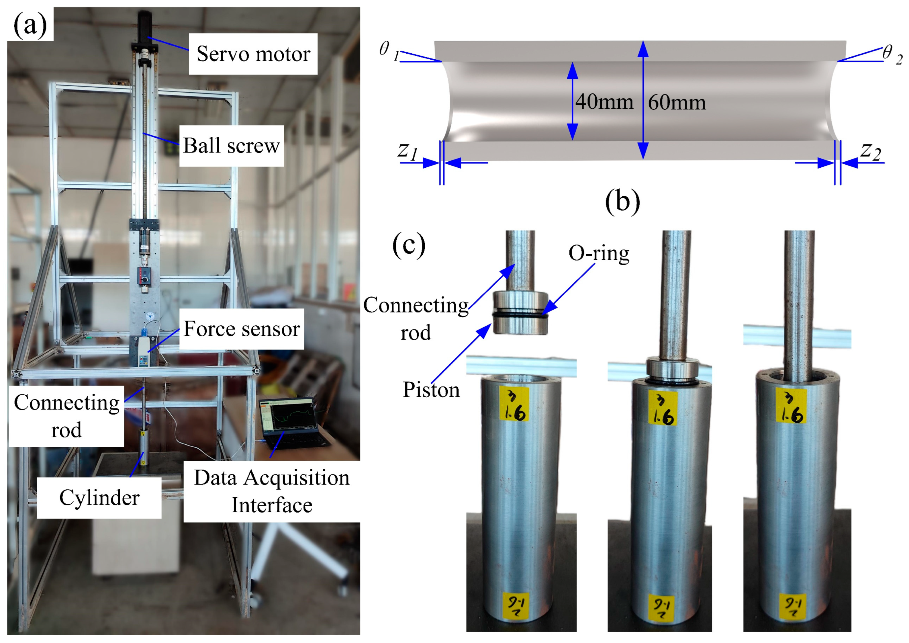
2.2.1. Experiment at Room Temperature and Atmospheric Pressure

Firstly, the IF and RF were measured at room temperature and atmospheric pressure. The variables of the experiment comprised the chamfer angle, chamfer length, and the roughness of the contact surface. The experimental setup is illustrated in Figure 4. Three cylinders were used in the experiment, and their parameters are detailed in Table 3. The test rig is equipped with a servo motor (Upper Standard Technology Co., Shanghai, China, DKC-Y240) and a ball screw module (Hymersen Co., Shenzhen, China, HMS40-T5-1500-M57-C4). A force sensor (Hengyuan Co., Bengbu, China, HYLF-010-2) was installed at the base of the screw to measure the axial force exerted on the O-ring. The components used in the experiments, including the cylinder, piston, and connecting rod, were fabricated from 316 stainless steel. During the experiment, the piston was actuated at velocities of 0.3 m/s and 0.5 m/s. However, the results did not indicate any statistically significant differences in resistance to movement that could be attributed to the varying speeds. The measurements corresponding to a piston speed of 0.3 m/s are presented below.

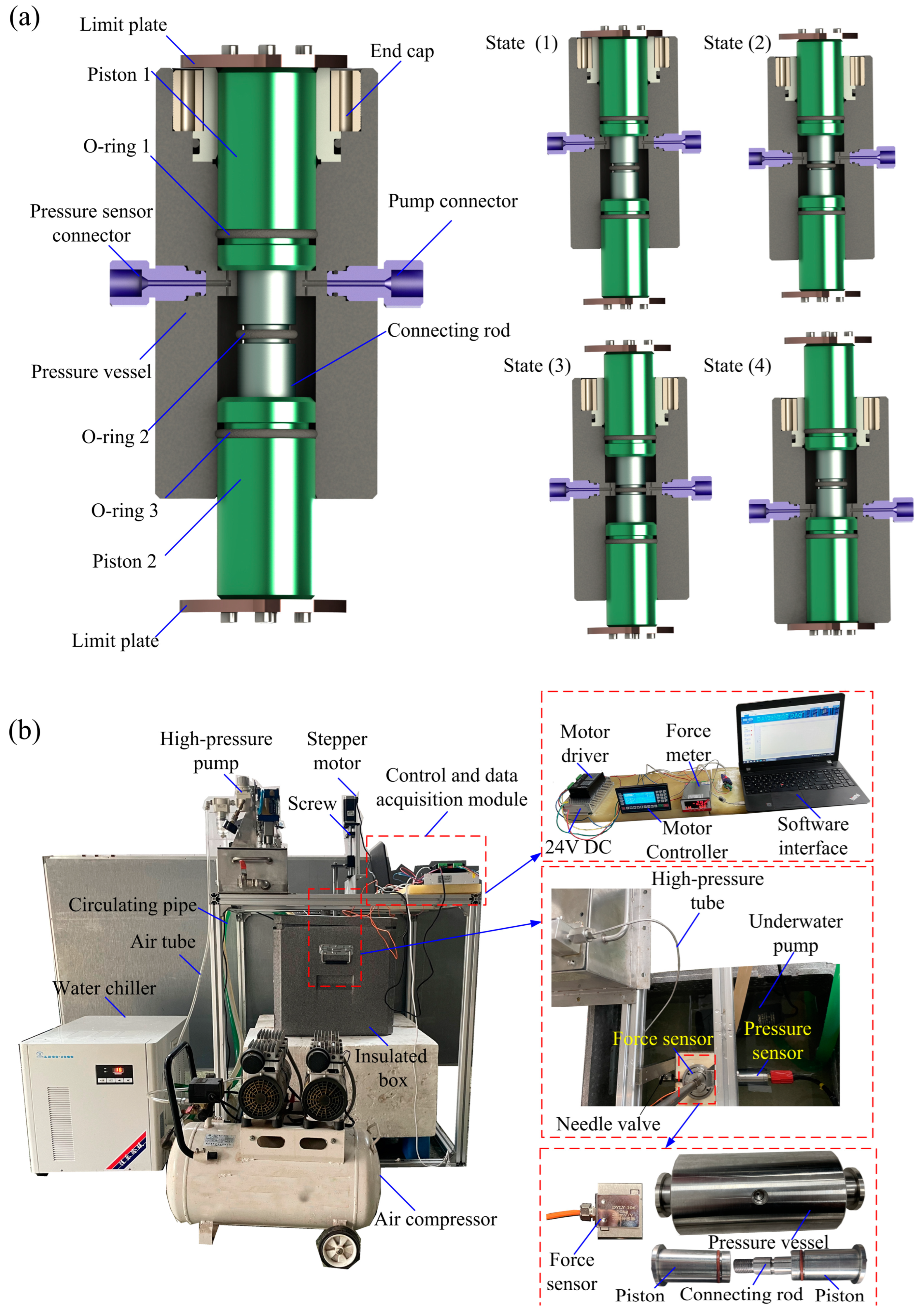
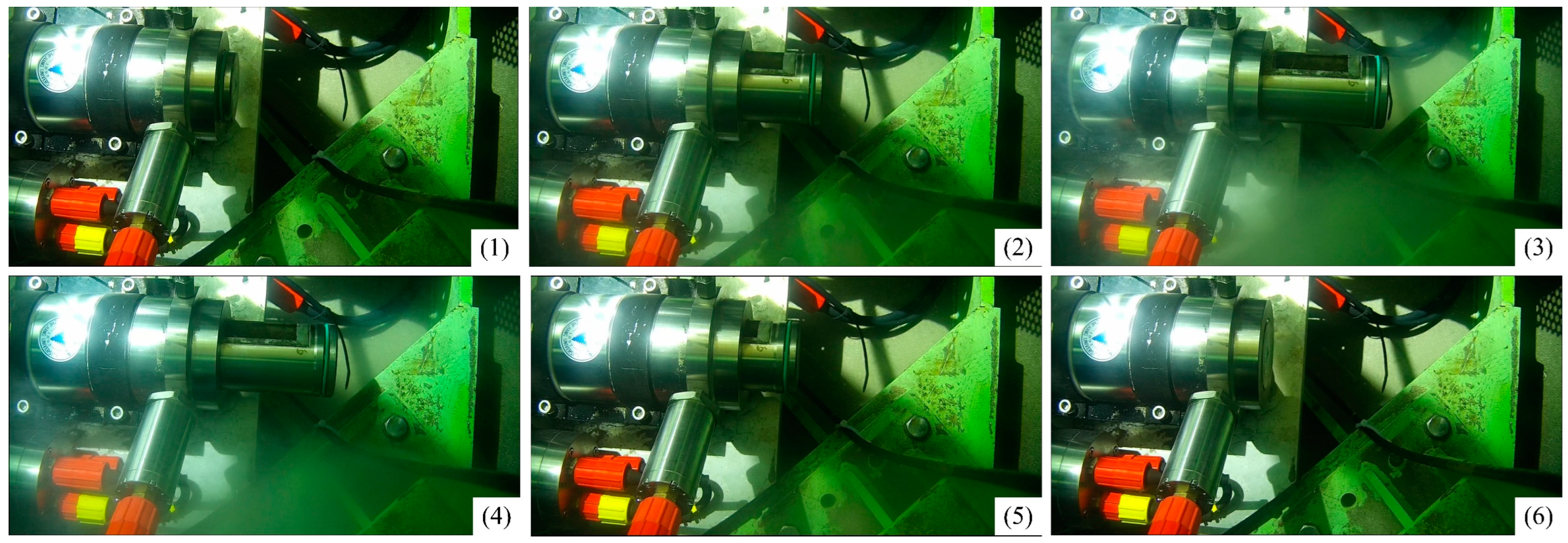
2.2.2. Experiment Under High Pressure and Low Temperature

A test rig, as illustrated in Figure 5a, was designed to measure the seal installation force and reciprocation friction under high-pressure, low-temperature conditions. Table 4 presents the dimensional parameters of the key parts of the test module. The pressure vessel was fabricated from 316 stainless steel and includes a centrally machined through-hole with a diameter of 24 mm. The two pistons and the connecting rod were made from precipitation-hardening stainless steel 17-4PH. Both the pistons and connecting rods were machined with housing for an O-ring. Additionally, two threaded holes were located on the lateral side of the pressure vessel for connecting the pressure sensor (Tuopu Electronic Instrument Co., Dongguan, China, PT124) and the booster pump (Jinran Co., Shanghai, China, 4DSY-120). The piston was connected to the force transducer via a double-end stud, and the force transducer (Dayang Co., Bengbu, China, DYLY-108) was connected to the linear actuator (Zhengyuan Co., Shenzhen, China, AM-BD45100AN) through a stainless-steel shaft. The friction measurement module was placed within a water bath environment inside an insulated box to facilitate testing at a specific temperature. A water chiller (Jiale heating engineering Co., Hefei, China LS27-1000) was used to circulate the water in the insulated box, ensuring a constant temperature. The assembled test rig is shown in Figure 5b.
As shown in Figure 5a, State (1) represents the initial position of the assemblies. At this stage, the motor drives the piston to perform an upward stroke. The output of the sensor (FO1) is the sum of f1 and f3 (the friction between the O-ring and the inner wall of the pressure vessel), as well as the gravity m (18.2 N) of the two pistons, the connecting rod, and the two limit plates (Equation (2)).
FO1 = f1 + f3 + m
In State (2) and State (3), O-ring 2 makes contact with the inner wall of the step. As a result, the installation and friction force of O-ring 2 (f2) is incorporated into the output of the sensor (FO2), as shown in Equation (3).
FO2 = f1 + f2 + f3 + m
As the forward stroke progresses, O-ring 2 detaches from the step until it reaches State (4), at which point the sensor’s output equals FO1. In this case, f1 is equal to f3, and both f1 and f2 can be expressed in Equations (4) and (5).
f 1 = F O 1 m 2
f2 = FO2FO1

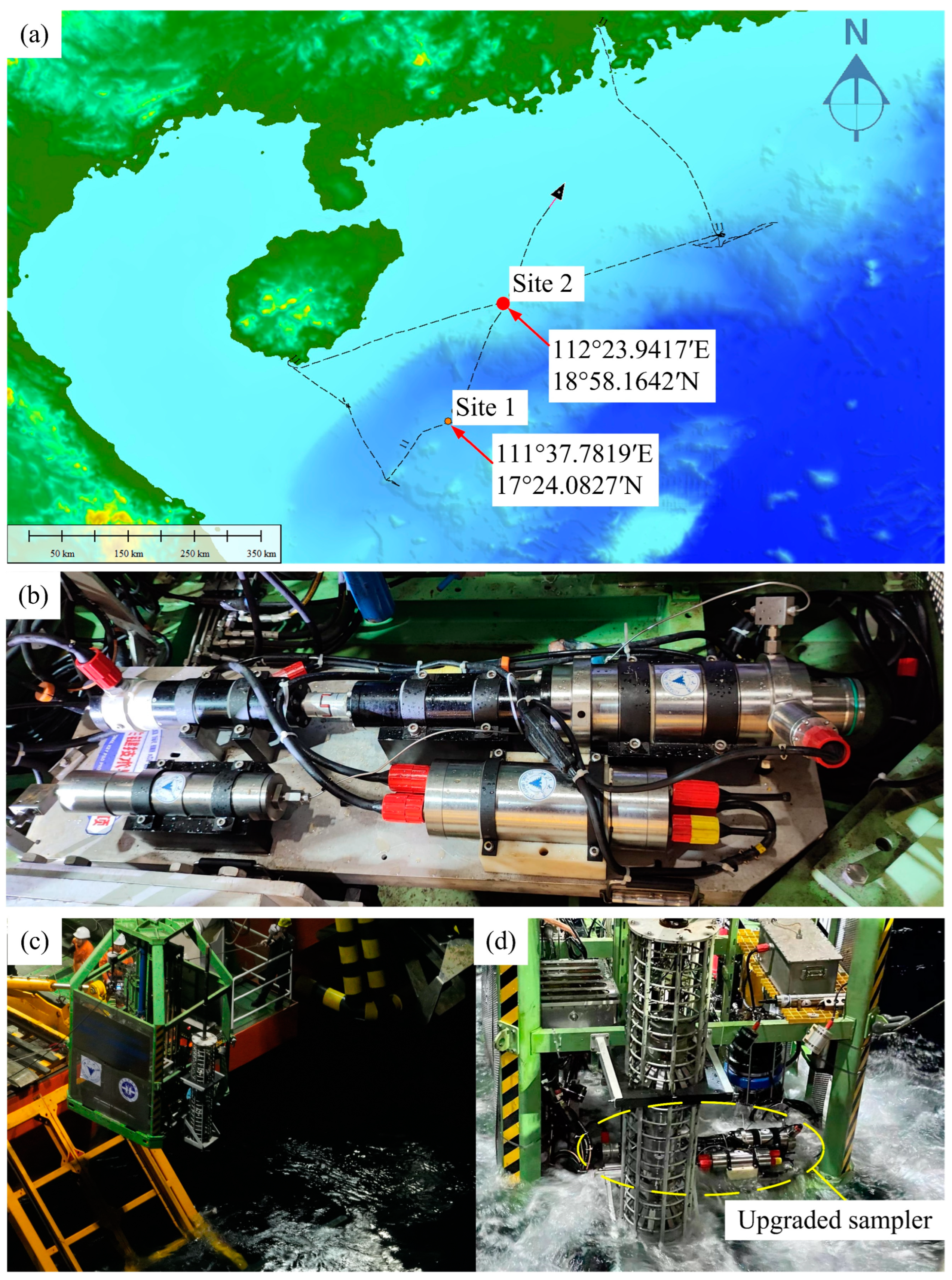
2.3. Field Test of the Upgraded Sampler

As previously mentioned, the failure of several in situ operations in the Mariana Trench demonstrated the lack of reliability of the developed sampler PMTI. Although the sampler performed adequately in certain tests, it did not meet the standards necessary for expensive deep-sea operations. Therefore, it is necessary to optimize the sampler. Based on the results of this paper, we modified the dimensions of the seal inlet chamfer of the sampling vessel by increasing the chamfer length from 1.5 mm to 2.5 mm and adjusting the chamfer angle from 20° to 25°. Moreover, we improved the roughness of the inner wall of the sample vessel, which was upgraded from Ra 1.6 μm to Ra 0.8 μm, which minimized the risk of seals becoming stuck. Furthermore, we increased the overload protection current of the motor by 0.3 A in the control program. During a marine scientific research cruise in May 2023, the upgraded sampler was field tested at the South China Sea (Figure 6).

3. Results

3.1. Results of Numerical Simulation

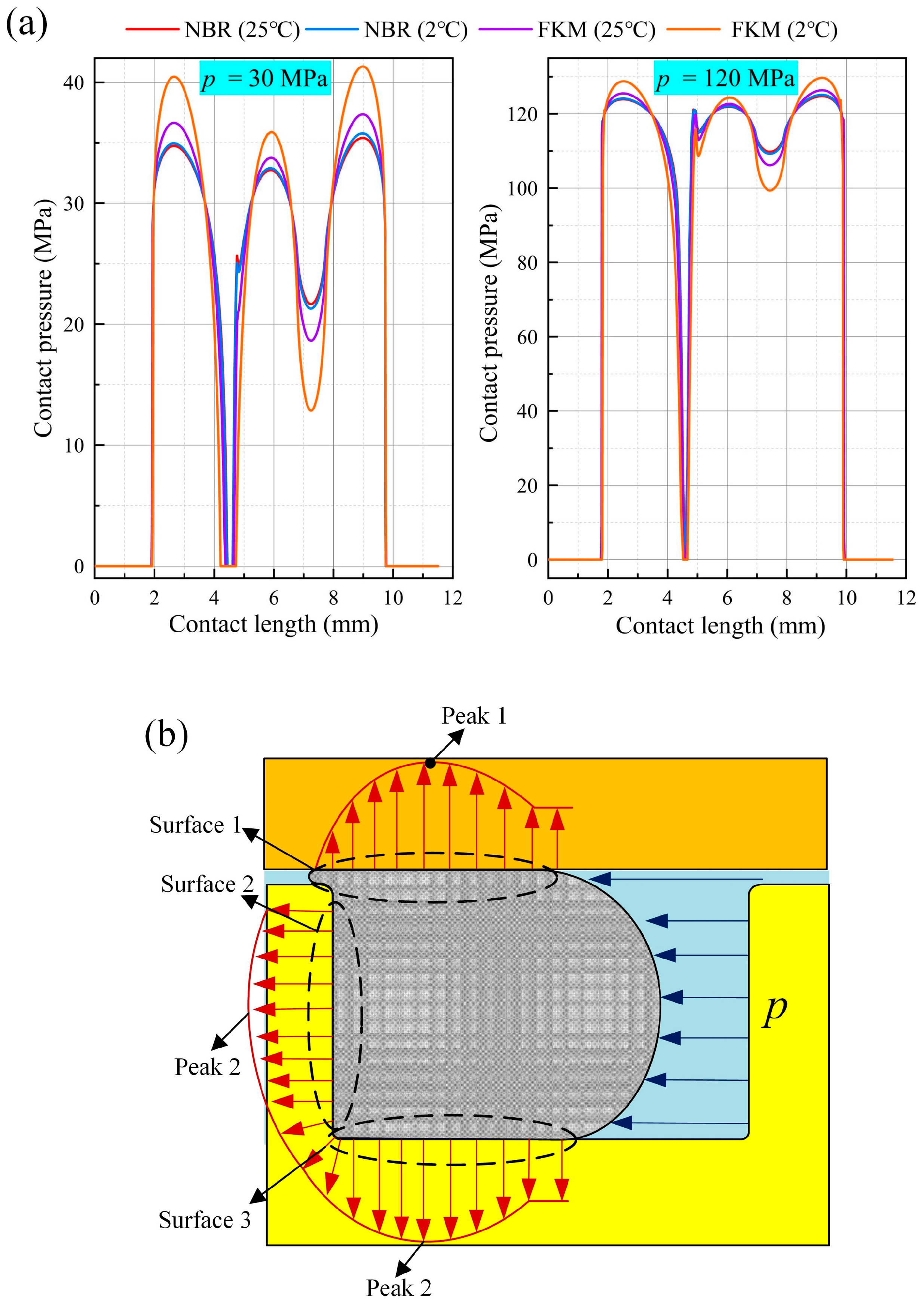
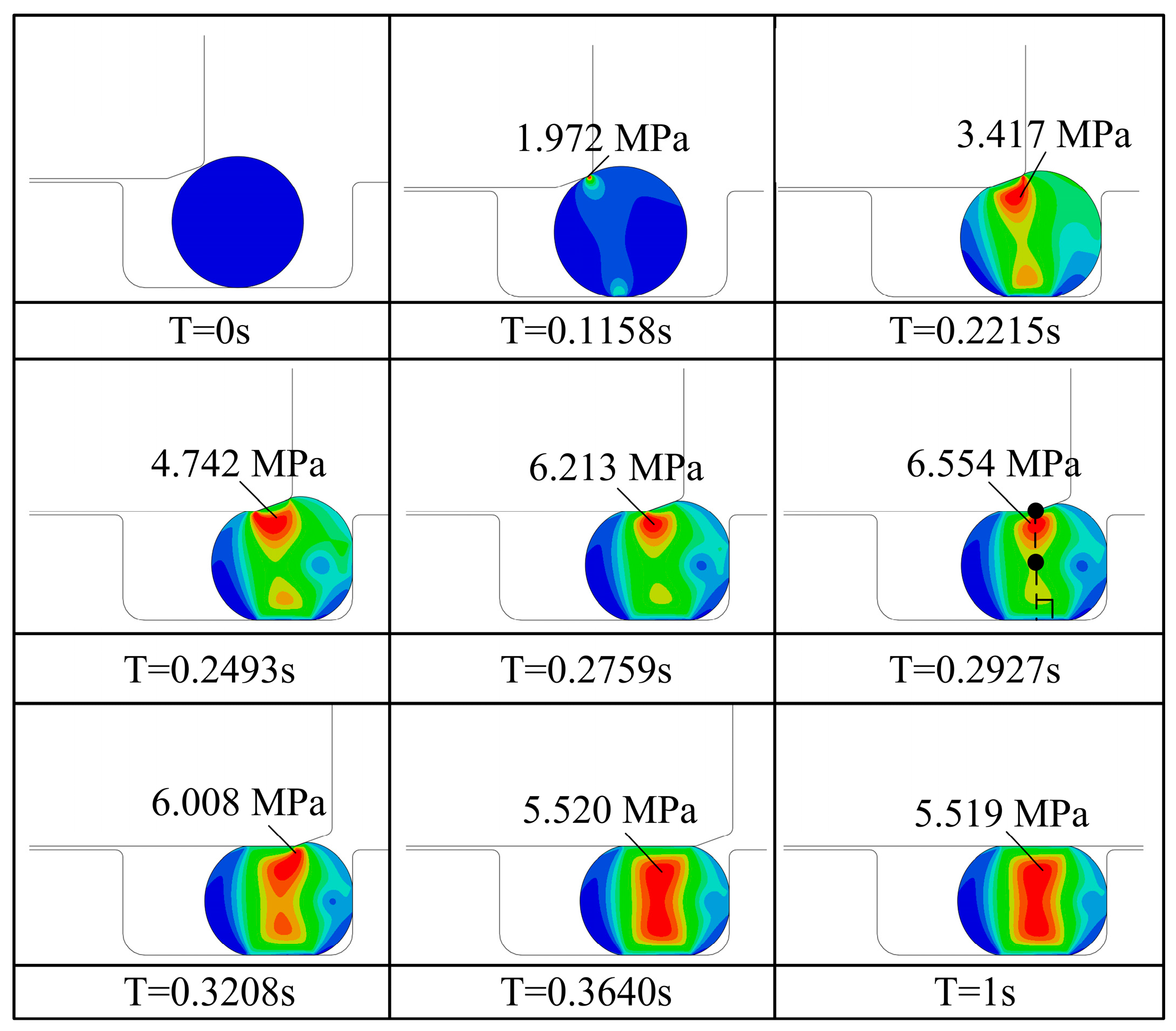
3.1.1. The Installation Force

Figure 7 shows the complete O-ring installation process (NBR, 2 °C, δ = 0.15 mm, θ = 20°, v = 0.5 m/s). As the sleeve moved, it pushed the O-ring towards the right side of the housing. The maximum IF of approximately 315.1 N is attained when the line connecting the chamfering point of the sleeve’s inner wall surface to the center of the O-ring is perpendicular to the piston axis (Figure 4, T = 0.2927 s, and Figure 5a, indicated by the purple line). At this moment, the Mises stress within the O-ring reaches its peak. In Figure 5, T represents the time of the initial analysis step.
Figure 8 illustrates the impact of δ, θ, v, and material properties on IF. The following conclusions can be drawn from the results: (1) IF exhibits a linear increasing trend as δ decreases. Specifically, for each 0.05 mm reduction in δ, IF increases by 80 to 90 N. (2) The chamfer angle significantly influences IF. Within the range of 10° to 20°, IF decreases as the chamfer angle increases. However, beyond 20°, the reduction in installation friction becomes negligible. (3) Within the velocity range of 0.3 m/s to 0.8 m/s, the relative motion velocity has minimal impact on IF. (4) When all other conditions remain constant, the ranking of the order of IF based on varying material parameters is as follows: FKM (2 °C) > FKM (25 °C) > NBR (2 °C) > NBR (25 °C). When the temperature decreases from 25 °C to 2 °C, IF increases by approximately 20 N for NBR and nearly 240 N for FKM, indicating a significant temperature dependence of these materials, with FKM being more significantly affected by temperature.

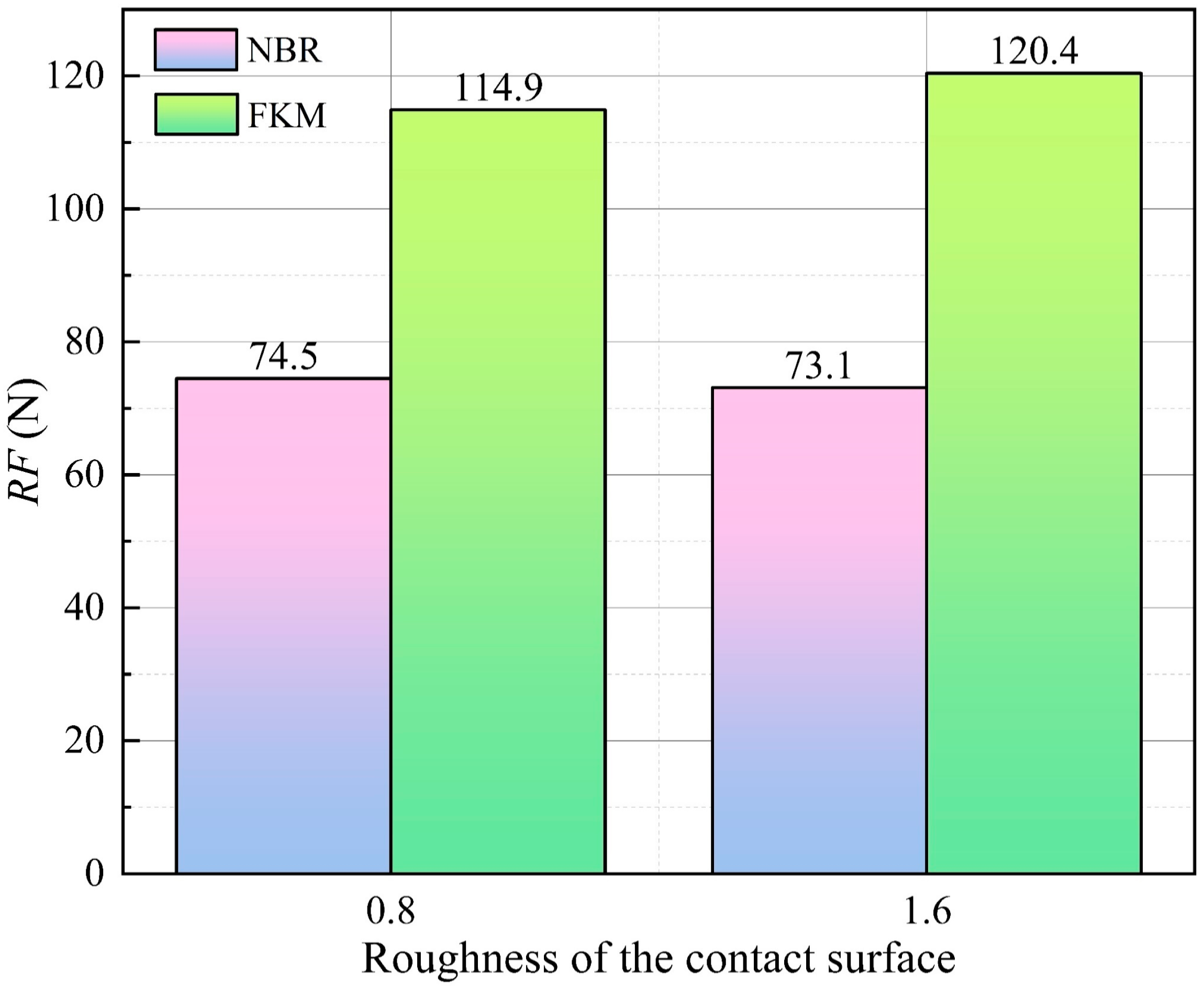
3.1.2. The Reciprocation Friction

Although the pressure-retaining samplers are capable of operating at full ocean depth, instances where the pressure difference between the sealing fluids on both sides of a moving O-ring exceed 30 MPa are rare. Consequently, the numerical simulation on RF is limited to a pressure of 30 MPa. The simulation results for the RF of O-rings with different material parameters are presented in Figure 9 (2 °C, δ = 0.15 mm, θ = 20°, v = 0.5 m/s). The results indicate a linear correlation between RF and pressure, with an approximate increase of 20 N in RF for every 1 MPa rise in pressure. The magnitude of RF, based on different material parameters, follows this order: FKM (2 °C) > FKM (25 °C) > NBR (2 °C) > NBR (25 °C). These findings suggest that selecting NBR as the sealing component in the design of deep-sea equipment can effectively mitigate the increase in motion resistance associated with low temperatures.

3.2. Results of Experimental Study

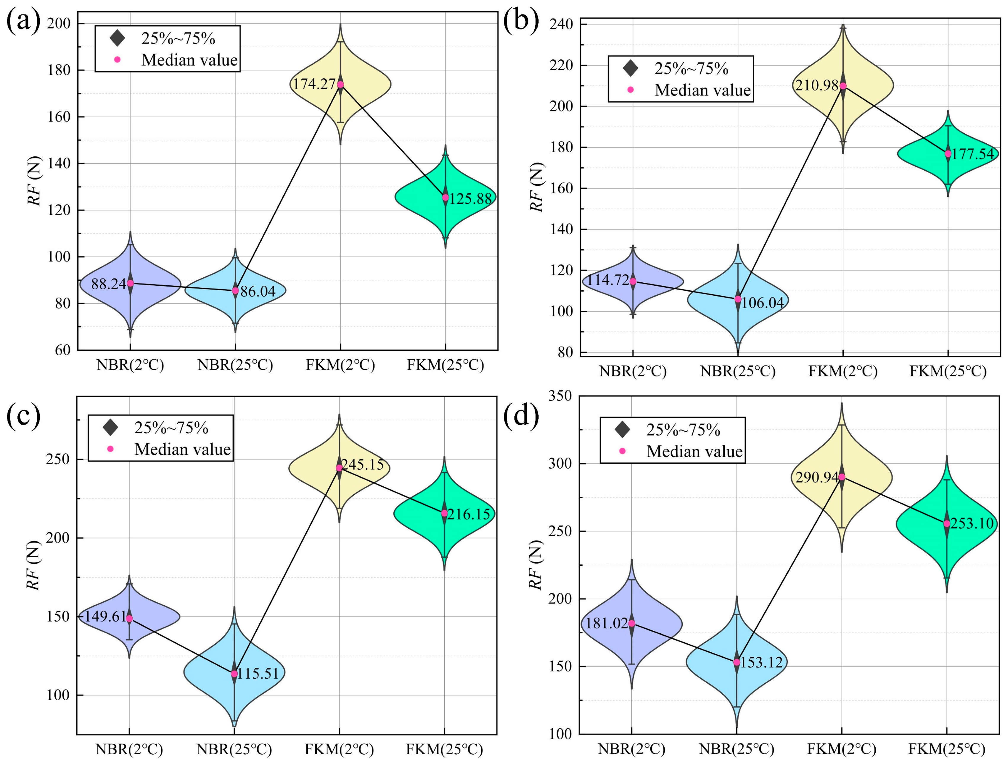
3.2.1. Results of Experiment at Room Temperature and Atmospheric Pressure

Figure 10 presents the results obtained from averaging five measurements of IF for NBR and FKM, and the experimental findings closely align with the simulation results. It is observed that increasing both the chamfer angle and chamfer length effectively reduces the IF; however, the impact of the chamfer angle on the IF is more significant than that of the chamfer length. Furthermore, the roughness of the contact surface appears to have a negligible impact on IF. Under identical chamfering parameters, the IF of FKM exceeds that of NBR. Figure 11 shows the RF results for both materials at surface roughness values of 0.8 μm and 1.6 μm. It is evident that surface roughness does not significantly influence RF when it varies within the range observed in the experiment.
The influence of inlet chamfer size and chamfer angle on IF obtained from the above experiments aligns with the results of the simulation analysis, thereby confirming the validity of the simulation findings. Additionally, the experimental results indicate that the effect of contact surface roughness on RF is not significant. In the next phase of our research, we will further investigate IF and RF under low-temperature and high-pressure conditions.

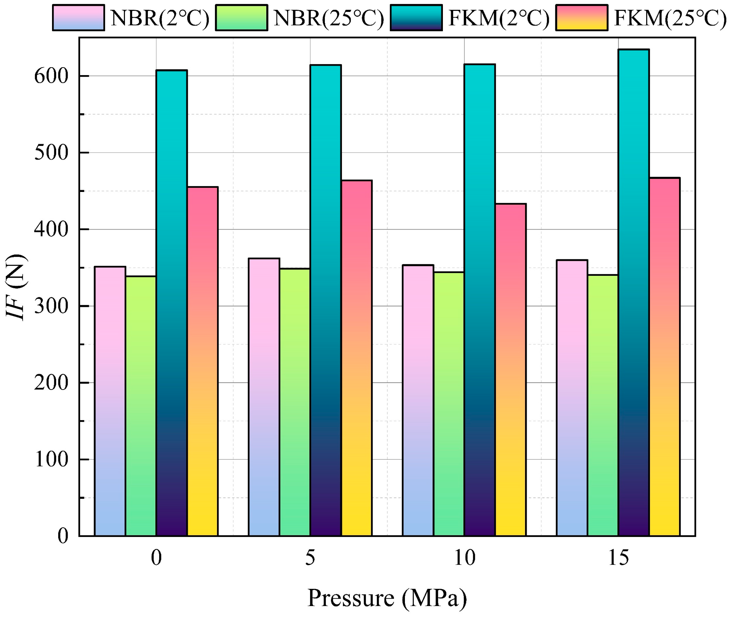
3.2.2. Results of Experiment Under High Pressure and Low Temperature

The test was conducted at an internal pressure ranging from atmospheric pressure to 15 MPa, constrained by the driving force of the motor utilized in the experiment. The results of the experiment are shown in Figure 12 and Figure 13.
The following conclusions can be drawn from the results obtained: (1) The magnitude of resistance follows the order FKM (2 °C) > FKM (25 °C) > NBR (2 °C) > NBR (25 °C), regardless of whether RF or IF is considered. This observation aligns with the findings of the numerical analysis. (2) A linear relationship is evident between RF and pressure; specifically, for every 1 MPa increase in pressure, RF increases by approximately 6.5 N. This value is significantly lower than the results derived from the simulation analysis, which may be attributed to the friction coefficient settings. In the simulation model, the friction coefficient is set at 0.15, whereas the lubrication conditions during the actual tests are significantly more favorable, resulting in experimental results that are markedly lower than those predicted by the simulation. (3) The diameter of the piston utilized in the experiment is 24 mm, and the experimental results shown in Figure 12 have been scaled to a diameter of 40 mm. The IF value obtained closely aligns with the simulation results, with an error margin not exceeding 10%, thereby confirming the validity of the simulation model.

3.3. Results of Experimental Study

Figure 14 presents the essential field verification data and schematically illustrates the seabed operation of the sampler under conditions where the ambient pressure exceeds 13 MPa and the temperature is approximately 3.5 °C. The sampling piston is fully retracted into the vessel, even with the use of the FKM seal. These observations experimentally demonstrate the effectiveness of the enhanced PMTI sealing structure.
The results of the field test are summarized in Table 5. Despite some seabed dust falling on the seals, the upgraded sampler presented good pressure-retaining performance. In the second test, the pressure-retaining rate exceeding 100% was attributed to the non-isobaric expansion of the vessel material and the seawater within it when the temperature increased.

4. Discussion

4.1. Advice for Selection of Seal Materials for Moving Parts of Deep-Sea Equipment

The results reveal the following three key thermodynamic coupling effects in deep-sea sealing systems: (1) The modulus elevation induced by the deep-sea environment in FKM synergistically combines with embrittlement (Tg ≈ −20 °C for FKM), resulting in a significant increase in the installation force [26]; (2) NBR demonstrates excellent thermal stability, and due to its saturated hydrocarbon structure [27], its resistance to motion does not exhibit a significant increase under high pressures and low temperatures; and (3) FKM shows a pronounced temperature dependence, with an exponential increase in kinematic resistance at low temperatures. Consequently, we have established NBR as the optimal dynamic sealing candidate for energy-efficient deep-sea actuators.
In addition, analyses of static sealing performance demonstrated that both materials achieved adequate interfacial stress for effective sealing. However, the contact pressure of FKM was 8–19% higher than that of NBR (at 20% compression), along with superior corrosion resistance properties. These characteristics make FKM the preferred choice for static sealing configurations.

4.2. Methods of Reducing the Installation Force of Sealing Ring

Our study reveals a crucial yet often overlooked phenomenon: the mounting force is consistently two to three times greater than the reciprocating friction force. This phenomenon warrants careful consideration when designing similar deep-sea devices. By integrating finite element modeling with the Mooney–Rivlin hyperelastic constitutive relation, we identified a critical geometric configuration for peak mounting resistance: when the vector connecting the chamfer apex to the center point of the O-ring forms a 90° angle with the piston axis (Figure 7). To minimize the installation force, adjustments can be made to the sealing gap and chamfer dimensions. In the redesigned PMTI frame, we increased the inlet chamfer to 25° and enhanced the surface roughness to Ra 0.8 µm through CNC grinding.

4.3. Limitations of This Study

By establishing a nonlinear finite element model that accounts for the temperature–pressure coupling effect (Section 3.1) and utilizing a self-developed deep-sea environment friction test platform (Figure 5), this study reveals the relationship between the installation force and the reciprocating friction of O-rings in deep-sea environments, as well as the influence of material and structural dimensions. However, some methodological constraints warrant acknowledgment. (1) This study demonstrates constraints related to material hardness, as indicated by its exclusive focus on NBR and FKM specimens standardized at Shore A 80 hardness. This work restricts a comprehensive assessment of elastomer performance variations across different hardness gradients (e.g., 70–90 Shore A), which may limit the predictive capabilities regarding the operational envelope for deep-sea sealing applications. (2) The torque limitations of the experimental drive system, constrained by budgetary parameters for instrumentation, imposed an operational pressure ceiling of 15 MPa for characterizing seal movement resistance. This threshold prevents direct measurement of interfacial friction dynamics at ultrahigh pressure.

5. Conclusions

A multi-method research framework that integrates numerical simulations and experimental studies was developed to elucidate the dynamic friction behavior of O-ring seals at low temperatures and high pressures (2 °C/30 MPa). The numerical model successfully predicted the evolutionary trends of O-ring assembly force and reciprocating motion friction, aligning with the experimental results. In future research, we aim to investigate the sealing mechanisms of deep-sea samplers operating in more extreme environments. Specifically, we will examine the properties of sealing elements subjected to the high-pressure and high-temperature conditions encountered by hydrothermal samplers. Furthermore, we will assess the impact of sediment particles adhering to the surfaces of sealing components on the performance of sediment samplers.

Author Contributions

Conceptualization, H.Z. and H.W.; methodology, Y.S. (Yanjie Sun); validation, Y.S. (Yongchun Shen); resources, Y.W.; data curation, J.C.; writing—original draft preparation, H.W.; writing—review and editing, H.W.; supervision, J.C.; project administration, H.W.; funding acquisition, H.W. All authors have read and agreed to the published version of the manuscript.

Funding

This research is supported by the National Natural Science Foundation of China (NSFC) Program (grant No. 42406185), the Natural Science Foundation of Shandong Province (grant No. ZR2024QD083), the National Key R&D Program of China (grant No. 2023YFB4704701), and the CSSC independent research project “Research on technology and method of demonstration and verification to deep-sea mining equipment”, 2022Z5.

Institutional Review Board Statement

Not applicable.

Informed Consent Statement

Not applicable.

Data Availability Statement

The data presented in this study are available upon request from the corresponding author. These data are not publicly available because of confidentiality concerns.

Acknowledgments

We are grateful to the pilots, the captain, and the crews of the R/V HAIYANGDIZHI 2 for their professional service during the cruises.

Conflicts of Interest

The authors declare no conflict of interest.

Appendix A

The capability of the deep-sea pressure-retaining sampler to preserve samples at in situ pressure is critically dependent on the reliability of the static seal. A geometric model, as illustrated in Figure A1, was developed to evaluate the static sealing performance of the seal within a pressure range of 0–120 MPa. The material and dimensional parameters utilized in the model are identical to those described in Section 2.1.1. The analysis was divided into the following two steps: (1) the pre-compression process of the O-ring was achieved through an interference fit (step time: 1 s); and (2) fluid pressure was applied via pressure penetration (step time: 1 s).
Figure A1. The geometry model for the static sealing performance study.
Applsci 15 01867 g0a1
Simulation results of static seal contact pressure for different material parameters under 30 MPa and 120 MPa are depicted in Figure A2. The contact pressure of both NBR and FKM exceeds the fluid pressure, indicating that they both have the ability to achieve reliable seals. NBR exhibits minimal sensitivity to temperature variations, as evidenced by the relatively small increases in contact pressure when subjected to lower temperatures; specifically, the temperature-induced increments of 30 MPa and 120 MPa conditions do not exceed 0.7 MPa. Conversely, FKM demonstrates a significant response to temperature changes, with a notable increase in contact pressure of approximately 4 MPa at lower temperatures. The observed order of maximum contact pressures is as follows: FKM (2 °C) > FKM (25 °C) > NBR (2 °C) > NBR (25 °C). Therefore, the application of FKM in static seals for deep-sea equipment is associated with enhanced sealing reliability.
Figure A2. Simulation results of static seal contact pressure for different material parameters. (a) Contact pressure under 30 MPa and 120 MPa. (b) Distribution and peaks of contact pressure.
Applsci 15 01867 g0a2

References

  1. Liang, J.; Feng, J.-C.; Zhang, S.; Cai, Y.; Yang, Z.; Ni, T.; Yang, H.-Y. Role of deep-sea equipment in promoting the forefront of studies on life in extreme environments. Iscience 2021, 24, 103299. [Google Scholar]
  2. Wang, H.; Cao, C.; Guo, J.; Wang, W.; Zhou, P.; Chen, J.-W. Design and friction loss study of full-ocean depth oil-filled direct current motor. J. Zhejiang Univ. Sci. A 2022, 23, 587–598. [Google Scholar]
  3. Wu, S.; Chen, Z.; Wang, S.; Zhang, J.; Yang, C. A review of deep-seawater samplers: Principles, applications, performance, and trends. Deep Sea Res. Part I Oceanogr. Res. Pap. 2024, 213, 104401. [Google Scholar]
  4. Elsyad, M.A.; Elhaddad, A.A.; Khirallah, A.S. Retentive properties of O-ring and locator attachments for implant-retained maxillary overdentures: An in vitro study. J. Prosthodont. 2018, 27, 568–576. [Google Scholar] [PubMed]
  5. Faulhaber, C.; Borland, C.; Boehm, R.; Heyne, J. Measurements of Nitrile Rubber Absorption of Hydrocarbons: Trends for Sustainable Aviation Fuel Compatibility. Energy Fuels 2023, 37, 9207–9219. [Google Scholar]
  6. Schaefer, R.J. Mechanical properties of rubber. In Harris’ Shock and Vibration Handbook; McGraw Hill: New York, NY, USA, 2010; Volume 6, pp. 33.18–33.31. [Google Scholar]
  7. Liao, C.; Huang, W.; Wang, Y.; Suo, S.; Liu, Y. Fluid-solid interaction model for hydraulic reciprocating O-ring seals. Chin. J. Mech. Eng. 2013, 26, 85–94. [Google Scholar]
  8. Wang, B.; Meng, X.; Peng, X.; Chen, Y. Experimental investigations on the effect of rod surface roughness on lubrication characteristics of a hydraulic O-ring seal. Tribol. Int. 2021, 156, 106791. [Google Scholar]
  9. Yanes Nunez, E. Frictional Behaviour of Elastomer Seals. Ph.D. Thesis, Queen Mary University of London, London, UK, 2023. [Google Scholar]
  10. Qin, Z.; Wu, Y.-T.; He, L.; Gao, X.; Lyu, S.-K. Empirical research on the friction behavior of O-rings in hydraulic cylinders. PLoS ONE 2023, 18, e0280815. [Google Scholar]
  11. Huang, H.C.; Ye, Y.Y.; Yang, C.J.; Leng, J.X.; Chen, Y. Study of the sealing characteristic of polytetrafluoroethylene-coated O-ring applied in gas-tight deep-sea water sampler. Adv. Mater. Res. 2011, 295, 3–10. [Google Scholar] [CrossRef]
  12. He, S.; Peng, Y.; Qiu, S.; Du, X.; Jin, Y. Sealing performance of sealing structure in a sediment sampler under ultra-high pressure. Sci. Rep. 2023, 13, 18548. [Google Scholar]
  13. Wu, J.-B.; Li, L. Influence of ambient pressure on sealing performance of O-ring in deep-sea hydraulic system. Ocean Eng. 2022, 245, 110440. [Google Scholar] [CrossRef]
  14. Liu, D.; Yun, F.; Jiao, K.; Wang, L.; Yan, Z.; Jia, P.; Wang, X.; Liu, W.; Hao, X.; Xu, X. Structural analysis and experimental study on the spherical seal of a subsea connector based on a non-standard O-ring seal. J. Mar. Sci. Eng. 2022, 10, 404. [Google Scholar] [CrossRef]
  15. Sun, S.; Zou, Y.; Zhang, Z.; Yang, Y.; Che, J.; Gong, Y. Simulation and Experiments on Sealing and Extrusion Failure on Application of Deep-Sea Adsorption by Differential Pressure. J. Press. Vessel. Technol. 2024, 146, 041701. [Google Scholar] [CrossRef]
  16. Han, Q.; Chen, H.; Yang, W.; Zhang, Y.; Yang, J.; Chen, Y. Analysis of reciprocating O-ring seal in the pressure-balanced oil-filled wet-mate electrical connectors for underwater applications. Lubr. Sci. 2019, 31, 335–345. [Google Scholar] [CrossRef]
  17. Li, Y.; Su, H.; Wang, Y.; Ma, Q.; Sun, H.; Lin, Z. Analysis of the factors influencing the sealing performance in subsea electrical connectors. Ships Offshore Struct. 2024, 20, 1–11. [Google Scholar] [CrossRef]
  18. Davies, P.; Le Gac, P.Y.; Ciausu, V.; Gallois, H. Testing of nitrile rubber joints for a deep submergence vehicle. Polym. Test. 2020, 90, 106630. [Google Scholar] [CrossRef]
  19. Wang, H.; Chen, J.-W.; Cao, C.; Ge, Y.; Fang, J.-S.; Zhou, P.; Lin, P.-W. Capturing amphipods in the Mariana Trench with a novel pressure retaining sampler. Deep Sea Res. Part I Oceanogr. Res. Pap. 2022, 184, 103772. [Google Scholar] [CrossRef]
  20. Yang, Y.; Zhao, W.; Xiao, X. The upper temperature limit of life under high hydrostatic pressure in the deep biosphere. Deep Sea Res. Part I Oceanogr. Res. Pap. 2021, 176, 103604. [Google Scholar] [CrossRef]
  21. Wang, H.; Ruan, D.-R.; Cao, C.; Fang, J.-S.; Zhou, P.; Fang, Y.-P.; Chen, J.-W. Collection sediment from Mariana Trench with a novel pressure-retaining sampler. Deep Sea Res. Part I Oceanogr. Res. Pap. 2022, 183, 103740. [Google Scholar] [CrossRef]
  22. Guo, J.; Chen, J.; Ren, Z.; Wang, H.; Zhang, P.; Wang, W.; Wang, Y.; Zhou, P.; Gao, Q.; Ren, X. Pressure-retaining sampler for sediment and overlying seawater based on heavy duty ROV-Jellyfish. Deep Sea Res. Part I Oceanogr. Res. Pap. 2023, 196, 104007. [Google Scholar] [CrossRef]
  23. He, S.; Qiu, S.; Tang, W.; Peng, Y.; Jin, Y.-P. A novel submersible-mounted sediment pressure-retaining sampler at full ocean depth. Front. Mar. Sci. 2023, 10, 1154269. [Google Scholar] [CrossRef]
  24. Rivlin, R.S.; Saunders, D. Large elastic deformations of isotropic materials VII. Experiments on the deformation of rubber. Philos. Trans. R. Soc. Lond. Ser. A Math. Phys. Sci. 1951, 243, 251–288. [Google Scholar]
  25. Zhou, C.; Zheng, J.; Gu, C.; Zhao, Y.; Liu, P. Sealing performance analysis of rubber O-ring in high-pressure gaseous hydrogen based on finite element method. Int. J. Hydrogen Energy 2017, 42, 11996–12004. [Google Scholar] [CrossRef]
  26. Nair, A.B.; Kurian, P.; Joseph, R. Ethylene–propylene–diene terpolymer/hexa fluoropropylene–vinylidinefluoride dipolymer rubber blends: Thermal and mechanical properties. Mater. Des. 2012, 36, 767–778. [Google Scholar] [CrossRef]
  27. Kumari, P.; Unnikrishnan, G. Thermal properties of compatibilized and filled natural rubber/acrylonitrile butadiene rubber blends. J. Therm. Anal. Calorim. 2013, 114, 67–75. [Google Scholar] [CrossRef]
Figure 1. The practical problem in this research was (a) the working principle of the pressure-retaining sampler and (b) the sampling piston failed to be retracted with an FKM O-ring.
Applsci 15 01867 g001
Figure 2. The geometry model for the reciprocating friction and installation force study.
Applsci 15 01867 g002
Figure 3. Test of mechanical properties. (a) Test specimen. (b) Test instruments.
Applsci 15 01867 g003
Figure 4. (a) Test rig; (b) cylinders for testing IF and RF; and (c) the installation process of the O-ring.
Applsci 15 01867 g004
Figure 5. The experiment setup. (a) Details of the test module. (b) Experimental setup.
Applsci 15 01867 g005
Figure 6. Field test of the upgraded sampler. (a) Test sites. (b) Sampler mounted on a geological exploration platform. (c) The platform deployment from the research vessel. (d) The platform was recovered.
Applsci 15 01867 g006
Figure 7. The installation process of the O-ring.
Applsci 15 01867 g007
Figure 8. Simulation results of installation force. (a) Relationship between δ and IF. (b) Relationship between θ and IF. (c) Relationship between v and IF; (d) Relationship between material and IF.
Applsci 15 01867 g008
Figure 9. Simulation results of reciprocation friction: (a) NBR (25 °C); (b) NBR (2 °C); (c) FKM (25 °C); and (d) FKM (2 °C).
Applsci 15 01867 g009
Figure 10. Test results of IF.
Applsci 15 01867 g010
Figure 11. Test results of RF.
Applsci 15 01867 g011
Figure 12. Results of IF.
Applsci 15 01867 g012
Figure 13. Results of RF (a) under atmospheric pressure; (b) under 5 MPa; (c) under 10 MPa; and (d) under 15 MPa.
Applsci 15 01867 g013
Figure 14. Upgraded sampler operating on the seafloor. (1)–(3) The process of pushing out the piston; (4)–(6): The process of retracting the piston.
Applsci 15 01867 g014
Table 1. Dimensions of O-ring seal structure.
SymbolDefinitionSetting Value
d1Out diameter of piston40 mm
d2Cross-section diameter of O-ring3.55 mm
δClearance between piston and cylinder0.1 mm–0.3 mm
hDepth of the O-ring housing2.75 mm
bwidth of the O-ring housing4.2 mm
r1Filet radius of at housing top0.4 mm
r2Filet radius of at housing bottom0.2 mm
θAngel of the lead-in chamfer10°, 15°, 20°, 25°
zLength of the lead-in chamfer2 mm
Table 2. Five-parameter Mooney–Rivlin constitutive model.
Material TypeC10C01C20C11C02
NBR (25 °C)1.5099−0.85100.6193−1.0989−0.2663
NBR (2 °C)5.8453−5.2729−2.29789.3654−10.8957
FKM (25 °C)4.9274−4.4537−1.06434.5278−6.3517
FKM (25 °C)5.4255−4.8963−1.23514.9735−6.4289
Table 3. Parameters of cylinders used in the experiment.
No.Chamfer Angle (°)Chamfer Length (mm)Roughness of the Contact Surface (μm)
1202, 31.6
2252, 31.6
3151, 20.8
Note: Ra was used in this study to describe the surface roughness. Ra represents the arithmetic mean of the absolute values of the contour deviations within a specified sampling length.
Table 4. Design parameters of key parts of the test module.
Part NameDesign Parameters
Pressure vessel40 mm in ID, 90 mm in OD, and 170 mm in length
Piston40 mm in diameter, 80 mm in length, and weighs 0.634 kg
Connecting rod24 mm in diameter, 110 mm in length, and weighs 0.291 kg
Limit plate70 mm in diameter, 5 mm in height, and weighs 0.129 kg
O-ring33.5 mm in ID, 3.55 mm in cross-section diameter
Table 5. Field test data of the upgraded sampler.
Test SiteDepth (m)In Situ/Final Pressure (MPa)In Situ Temperature (°C)Pressure-Retaining Rate
1128813.3/13.53.1101.5%
22562.7/2.65.396.3%
Note: In situ pressure refers to the seafloor pressure recorded on the depth gauge of the geological exploration platform when it reaches the seafloor. Final pressure is the pressure within the chamber of PMIT as measured by the pressure transducer after the sampler has been recovered. The pressure-retaining rate is calculated as follows: (final pressure/in situ pressure) × 100%.
Disclaimer/Publisher’s Note: The statements, opinions and data contained in all publications are solely those of the individual author(s) and contributor(s) and not of MDPI and/or the editor(s). MDPI and/or the editor(s) disclaim responsibility for any injury to people or property resulting from any ideas, methods, instructions or products referred to in the content.

