Article

Lateral Load-Bearing Performance of a Long Pile in Layered Soils Based on the Modified Vlasov Foundation Model

1
School of Civil Engineering and Architecture, Henan University of Science and Technology, Luoyang 471023, China
2
Henan Construction Safety and Protection Engineering Technology Research Center, Luoyang 471023, China
*
Author to whom correspondence should be addressed.
Appl. Sci. 2025, 15(4), 1759; https://doi.org/10.3390/app15041759
Submission received: 12 December 2024 / Revised: 14 January 2025 / Accepted: 6 February 2025 / Published: 9 February 2025
(This article belongs to the Special Issue Advances and Challenges in Rock Mechanics and Rock Engineering)

Abstract

:
A mechanical model of a laterally loaded long pile in layered soils was established to accurately calculate the lateral load-bearing performance of the pile foundation, and attention was paid to the influence of the complete separation of the pile–soil contact surface in a certain part of the pile on its lateral load-bearing performance. Based on the modified Vlasov foundation model, the displacement equation of the laterally loaded long pile embedded in layered soils was derived by the separation variable method. Using the solution method presented in this study, the deformation and internal force of the free-fixed pile were obtained. Then, the effects of the slenderness ratio of the pile and the complete separation of the pile–soil contact surface on the lateral load-bearing performance of the long pile in layered soils were analyzed. The results show that the deformation of the pile body increases with the increase in the slenderness ratio under the lateral load. Meanwhile, the position of the maximum bending moment and the negative shear force moves upward along the pile as the slenderness ratio increases. When the contact surface of the pile–upper stratum is separated, the deformation of the pile top doubles, and the negative shear force increases by three times compared to the case without the effect of separation of the pile–soil contact surface. When the contact surface between the pile and the middle layer soil is separated, the deformation and bending moment of the pile increase by 25%, and the maximum negative shear force decreases.

1. Introduction

With the rapid development of megaprojects such as supertall buildings and cross-sea bridges, the application of long and ultra-long pile foundations has become increasingly widespread. Under complex geological and environmental conditions, such as seismic events and scouring, the lateral load-bearing performance of these piles has emerged as a critical challenge in engineering design [1,2,3,4,5]. Due to the diversity of site conditions and loading forms, pile foundations are required to exhibit high lateral load-bearing capacity in addition to supporting axial loads [6,7,8,9]. To more accurately describe the mechanical characteristics of laterally loaded long piles, significant progress has been made in modeling theories and computational methods by scholars both domestically and internationally [10,11,12].
The mechanical behavior analysis of laterally loaded long piles is a core issue in soil–structure interaction research, closely related to the selection and applicability of the foundation models [13,14,15]. An accurate foundation model is not only a key tool for comprehensively understanding the mechanical behavior of pile foundations under complex geological conditions but also serves as an important basis for guiding practical engineering design. Dahal et al. conducted a systematic study on the selection of an appropriate constitutive model for deep excavation optimization, emphasizing the importance and rationality of model selection [16]. Existing research has demonstrated that the Vlasov foundation model, with its clear physical significance and precise characterization of pile–soil interaction, has significant advantages in capturing the impact of the foundation on the lateral load-bearing performance of piles [17,18]. Compared to traditional Winkler and Pasternak models, the Vlasov model is better suited for simulating the complexity of layered foundations and the continuity of soil, particularly in describing the deformation and internal force distribution of pile foundations under lateral loads [19].
From the perspective of practical engineering needs, recent years have witnessed increasing attention to the static and dynamic mechanical characteristics of laterally loaded piles in layered foundations, providing a reliable theoretical basis for pile foundation design under complex conditions [20,21,22,23,24]. The study by Arshad et al. focuses on the dynamic response of a single pile under long-term, repeated loading and proposes a new method for calculating bearing capacity [25]. Zhang et al. demonstrated that pile head stiffness significantly influences lateral displacement and bending moment distribution [26]; Xiong Hui et al., using the Laplace transform method, proposed a new lateral vibration impedance model that not only improves computational efficiency but also reveals the key influence of soil layer stiffness on pile dynamic responses [27]. Further, Zhang Min et al. found that flexible constraints at the pile head during horizontal vibration significantly alter the dynamic characteristics of pile foundations, offering new insights for optimizing pile foundation design under complex conditions [28]. Li et al. investigated the resonance compaction effect of laterally loaded piles in layered soils and proposed an improved foundation reinforcement method [29]. Kavitha et al. reviewed the efficiency of laterally loaded pile groups and suggested correction factors for bearing capacity under different soil layering conditions [30]. Kim et al. utilized a three-dimensional finite element method to analyze soil resistance around piles in clay, revealing the impact of boundary effects on pile foundation performance [31]. These studies collectively indicate that accurately analyzing the impact of varying soil layer properties and structural conditions on pile mechanical performance is fundamental to ensuring the safety and reliability of pile foundation design.
In terms of theoretical analysis methods, semi-analytical methods, transfer matrix methods, and continuum-mechanics-based approaches have been widely applied to study the mechanical performance of pile foundations under lateral loads [32,33]. For example, Zhang et al. obtained a semi-analytical solution for pile performance under coupled longitudinal and lateral loads using the transfer matrix method, providing an efficient tool for mechanical analysis under complex loads [34]; Dai Zihang and Chen Linjing adopted the finite difference method and elastic foundation beam finite element method to study the lateral deformation and internal force distribution of piles in layered foundations [35]. However, these studies mostly assume a perfect pile–soil contact interface, neglecting the potential influence of local detachment at the pile–soil interface, which may occur in practical engineering scenarios.
In reality, laterally loaded long piles, especially those with large slenderness ratios, may undergo significant deformation under loading, leading to local detachment at the pile–soil interface. This phenomenon not only alters the internal force distribution of the pile but also significantly impacts its load-bearing path [36,37]. For instance, Yang Jibao found that local contact detachment could increase pile head negative shear forces by up to three times [38]; Jiang Jianping further pointed out that under local scour conditions, contact detachment significantly amplifies pile bending moments and deformations, thereby reducing pile stability, which is particularly pronounced in post-seismic liquefied soil layers [39]. Moreover, introducing dynamic soil–structure interaction models enables a more comprehensive description of the effects of local contact detachment on the mechanical performance of pile foundations [40,41]. Experimental studies by Richter et al. revealed that increasing the stiffness of the soil layers around the pile head and foundation can significantly enhance the lateral load-bearing capacity of pile foundations, offering new strategies for pile foundation design under complex geological conditions [42]. However, existing research has primarily focused on the overall load-bearing behavior of piles under lateral loads, with insufficient attention to the impact of local interface detachment. This oversight may lead to an overestimation of pile mechanical performance in practical engineering, particularly under post-seismic and complex geological conditions, posing potential safety risks.
Based on the above analysis, further exploration of the effects of local pile–soil contact detachment on the lateral performance of piles, especially the mechanical response in complex multilayered foundations, is of significant theoretical and engineering value. This research can deepen the understanding of pile deformation and internal force distribution while providing a scientific basis for post-seismic repairs and optimized designs.
This study investigates the mechanical behavior of laterally loaded long piles with local pile–soil detachment in layered foundations, emphasizing the influence of partial detachment on pile performance—an aspect often overlooked in conventional analyses. By employing the modified Vlasov foundation model and the separation of variables method, this research systematically derives analytical solutions for pile deformation and internal forces in both complete contact and local detachment scenarios. Unlike traditional models assuming full pile–soil contact, this study introduces a more realistic consideration of local detachment, providing a novel approach to quantifying its impact on lateral deformation, bending moments, and shear forces. The findings offer new insights and quantitative guidance for optimizing pile foundation design in complex layered soils, contributing to safer and more reliable geotechnical engineering practices.

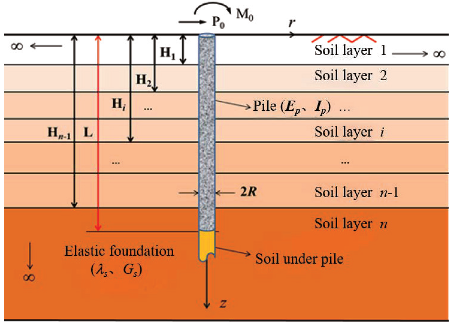
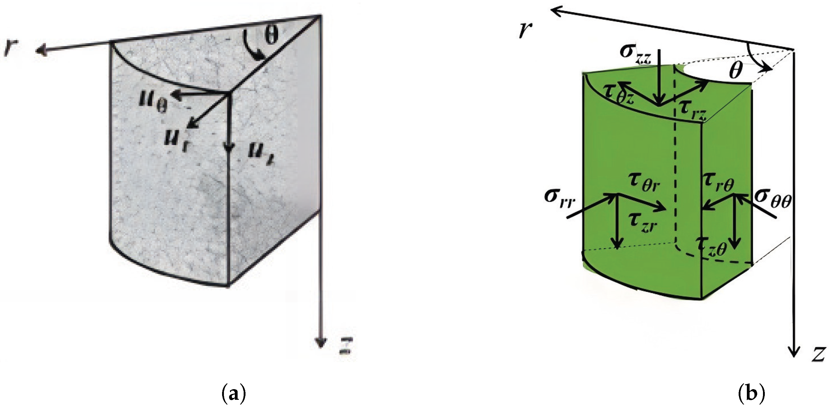
2. Computation Model

The focus of this paper is on laterally loaded long piles in layered foundations. As shown in Figure 1, P 0 and M 0 represent the transverse load and bending moment, L is the pile length, R is the pile radius, and E p and I p are the elastic modulus and moment of inertia of pile body, respectively. The pile body is embedded in the n-layer elastic foundation, where H i denotes the depth of the bottom surface of the i-th layer foundation, and λ si and G si are the Lamé constants of the i-th layer foundation. The cylindrical coordinate system is established with the central axis of the pile as the z-axis. Any point in the coordinate system can be represented by the radial coordinate r, the circumferential coordinate θ , and the vertical coordinate z.
As shown in Figure 2, u θ ( z , r ) and u r ( z , r ) represent the lateral displacement of the soil field around the pile, and u z ( z , r ) represents the axial displacement. To facilitate the analysis and highlight the research focus of this paper, the following assumptions are made: (1) Both the foundation and the pile are considered as linearly elastic isotropic bodies. (2) The pile–soil contact surface friction is ignored. (3) If the pile–soil contact surface of a stratum is detached, the pile–soil interaction of the stratum is completely ignored. (4) The deformation of the pile is assumed to be in an elastic state, and there is a nonlinear effect of the pile–soil interaction. The axial displacement of the pile foundation is ignored, and only the lateral displacement u θ ( z , r ) and u r ( z , r ) of the elastic foundation is considered as follows [43,44]:
u r ( z , r ) = w ( z ) ϕ ( r ) cos θ u θ ( z , r ) = w ( z ) ϕ ( r ) sin θ
where w ( z ) is the lateral displacement of the pile foundation; ϕ ( r ) is the attenuation function of foundation displacement along the radial direction r. From the geometric relationships in cylindrical coordinates, we can derive the following Equation (2) based on Equation (1):
ε r r ε d θ ε z z γ r z γ θ z = u r r u r r u θ θ u z z 1 r u r θ u θ r + u θ r u z r u r z 1 r u z θ u θ z = w ( z ) d ϕ ( r ) d r cos θ 0 0 w ( z ) d ϕ ( r ) d r sin θ d w ( z ) d z ϕ ( r ) cos θ d w ( z ) d z ϕ ( r ) sin θ
Consequently, the elastic foundation physical equation in cylindrical coordinates is as follows:
σ r r σ θ θ σ z z τ r θ τ θ z τ θ z = λ s + 2 G s λ s λ s 0 0 0 λ s λ s + 2 G s λ s 0 0 0 λ s λ s λ s + 2 G s 0 0 0 0 0 0 G s 0 0 0 0 0 0 G s 0 0 0 0 0 0 G s ε r r ε θ θ ε r θ γ r θ γ r z γ θ z
According to the principle of minimum potential energy [44], the total potential energy of the pile–soil system is as follows:
= U V = 1 2 R 0 2 π 0 σ r r ε r r + σ r θ ε θ θ + σ = ε z z + τ r θ γ r θ + τ r z γ r z + τ θ z γ θ z rd r d z + 1 2 0 L E p I p d 2 w d z 2 2 d z + 1 2 L π R 2 G s ( d w d z ) 2 d z P 0 w M 0 d w d z
By substituting Equations (2) and (3) into Equation (4), the following can be obtained:
0 R π λ s + 3 G s w d ϕ d r δ w d ϕ d r + 2 π G s d w d z ϕ δ d w d z ϕ r d r d z + 0 L E p I p d 2 w d z 2 d 2 w d z 2 d z + L π R 2 G s d w d z δ ( d w d z ) d z P 0 δ w M 0 δ d w d z = 0
Based on the modified Vlasov foundation model, which accounts for soil continuity and varying properties with depth, this approach improves accuracy in predicting pile behavior in layered foundations. It offers better pile–soil interaction modeling and computational efficiency compared to traditional methods. For clarity, we use a pile in a three-layer foundation as an example:
i = 1 3 H i 1 H i ( E p I P d 4 w i d z 4 + k i w i 2 t i d 2 w i d z 2 ) δ w i d z L ( k 3 w 4 2 t 4 d 2 w 4 d z 2 ) δ w 4 d z + i = 1 2 E p I p d 3 w i d z 3 + 2 t i d w i d z δ w i + E p I p d 3 w i + 1 d z 3 2 t i + 1 d w i + 1 d z δ w i + 1 z = H i E p I p d 3 w 1 d z 3 2 t 1 d w 1 d z P 0 δ w 1 | z = 0 + 2 t 4 d w 4 d z δ w 4 | z = + E p l p d 2 w 1 d z 2 + M 0 δ d w 1 d z | z = 0 + E p I P d 3 w 3 d z 3 + 2 t 3 d w 3 d z δ w 3 2 t 4 d w 4 d z δ w 4 z = L + i = 1 2 E p I p d 2 w i d z 2 δ d w i d z E p I p d 2 w i + 1 d z 2 δ d w i + 1 d z | z = H i + E p I p d 2 w 3 d z 2 δ d w 3 d z | z = L + R π m s ( d 2 ϕ d r 2 r + d ϕ d r ) 2 π n s ϕ r δ ϕ d r + π m s d ϕ d r r δ ϕ | R = 0
where
t i = π G s i R ϕ 2 r d r ; t 4 = π G s 3 R ϕ 2 r d r + 1 2 π G s 3 R 2 ; ( z [ L , ) ) ; n s = i = 1 3 G s i [ H i H i 1 ( d w d z ) 2 d z ; i = 1 , 2 , 3 ; H 0 = 0 ; H 3 = L ; m s = i = 1 3 λ s i + 3 G s i H i 1 H i w i 2 d z ; k i = π λ s i + 3 G s i R d ϕ d r 2 r d r .
To facilitate analysis, dimensionless parameters are introduced:
t i * = 2 α i ξ i λ 2 ( 1 + ν s i ) ; k i * = 2 ( 3 4 ν s i ) α i η λ 4 ( 1 + ν s i ) ( 1 2 ν s i ) ; t 4 * = 2 α i ξ 2 λ 2 ( 1 + ν s i ) ; P 0 * = 4 P 0 L 2 π R 4 E p ; M 0 * = 4 M 0 L π R 4 E p ; z * = z L ; w i * = w i L .
where ν s i is the Poisson’s ratio of the i-th layer foundation, and α i = E s i / E p is the elastic modulus ratio of the i-th layer foundation to the pile,
ξ 1 = 1 R 2 R ϕ 2 r d r ; η = R d ϕ d r 2 r d r ; ξ 2 = 1 R 2 R ϕ 2 r d r + 1
By substituting Equation (8) into Equation (6), the dimensionless displacement control equation for the pile in the i-th layer foundation can be obtained:
i d 4 w i * d z * 4 + k t * w i * 2 t t * d 2 w i * i d z * 2 = 0
According to the pile foundation constraint, the upper boundary condition is as follows ( z * = 0 ):
d 3 w 1 * d z * 3 2 t 1 * d w 1 * d z * P 0 * = 0 d 2 w 1 * d z * 2 + M 0 * = 0 ( Free ) d w 1 * d z * = 0 ( Fixed )
The deformation of the pile foundation at the interface between the i-th layer foundation and the ( i + 1 ) -th layer foundation is continuous, then we have the following ( z * = H i / L , i = 1 , 2 ):
w i * = w i + 1 * ; d w i * d z * = d w i + 1 * d z * ; d 2 w i * d z * 2 = d 2 w i + 1 * d z * 2 ; d 3 w i * d z * 3 2 t i * d w i * d z * = d 3 w i + 1 * d z * 3 2 t i + 1 * d w i + 1 * d z *
Correspondingly, the lower boundary condition is as follows ( z * = 1 ):
w 3 * = 0 ; d w 3 * d z * = 0 ; d 2 w 3 * d z * 2 = 0 ; d 3 w 3 * d z * 3 2 t 3 d w 3 * d z * 2 k 3 * t 4 * w 3 * = 0
The governing equation of the attenuation function can be obtained by the coefficient δ ϕ in Equation (6):
d 2 ϕ d r 2 + 1 r d ϕ d r ( γ R ) 2 ϕ = 0
where γ R 2 = 2 n s m s , and γ is the dimensionless attenuation coefficient. The boundary conditions are: ϕ ( R ) = 1 ; ϕ ( ) = 0 ; the solution is as follows:
ϕ r = K 0 γ / R r K 0 γ
where K 0 ( ) is the second kind of zero-order Bessel function,
γ = 1 φ i = 0 2 G s i H i * H i + 1 * ( d w i * d z * ) 2 d z * + G s 3 w 3 * 2 | z * = 1 k 3 * / 8 t 4 * i = 0 2 ( λ s i + 3 G s i ) H i * H i + 1 * w i * 2 d z * + ( λ s 3 + 3 G s 3 ) w 3 * 2 | z * = 1 t 4 * / 2 k 3 *
where H i * = H i / L , H i + 1 * = H i + 1 / L , H 0 * = 0 , H 3 * = 1 .
Given that one of the primary focuses of this paper is the phenomenon of local pile–soil contact surface detachment in layered foundations, and to clearly demonstrate its impact on the mechanical behavior of piles, this study specifically considers the scenarios where certain soil layers are fully detached from the pile. Such detachment typically occurs due to insufficient lateral confinement provided by the surrounding soil or differential settlement under lateral loading conditions. By analyzing these extreme conditions, we aim to provide a comprehensive understanding of how pile–soil detachment affects lateral deformation, bending moments, and shear forces along the pile shaft.
Based on Equation (10) and the specified boundary conditions, the displacement control equation for the pile at the pile–soil contact interface is derived by incorporating the interaction effects of degraded pile–soil contact. For brevity, the detailed derivation process is omitted, but the resulting equation forms the basis for subsequent parametric analysis. This approach allows us to quantify the extent to which local detachment influences the overall mechanical performance of piles in layered soil, offering practical insights for pile foundation design.

3. Solution Process

The general solution for the displacement of the pile foundation in the i-th layer foundation is as follows:
w i * ( z * ) = C i 1 f i 1 + C i 2 f i 2 + C i 3 f i 3 + C i 4 f i 4
where C i 1 , C i 2 , C i 3 , and C i 4 are undetermined coefficients. The expressions of f i 1 , f i 2 , f i 3 , and f i 4 are shown in Table 1 [45].
To simplify the formulation process, the dimensionless notation superscript is omitted in the subsequent derivations. The first-order derivative with respect to the variable z is denoted in a simplified manner. Taking a rock-socketed pile as an example, the boundary conditions can be reduced to a free-fixed support configuration, where the pile head is free and the pile base is fixed. This simplification accurately reflects the behavior of embedded piles in lateral loading in practical engineering scenarios and provides a clear basis for deriving analytical solutions.
w 1 ( 0 ) = M 0 ; w 1 ( 0 ) 2 t 1 w 1 ( 0 ) = P 0 ; w 3 ( L ) = 0 ; w 3 ( L ) = 0 .
By substituting Equation (17) into Equations (12) and (18), the following is obtained:
M C i = N
where { C i } is the undetermined coefficient matrix and [ M ] is the solution function matrix, N = M 0 P 0 0 0 T ,
M = A ( 0 ) B B D 1 ( H 1 ) D 2 ( H 1 ) B B D 2 ( H 2 ) D 3 ( H 2 ) B B E 3 ( L )
B is a zero matrix, and A 1 ( 0 ) , D i ( H j ) ( i = 1 , 2 , 3 ; j = 1 , 2 ) , and E 3 ( L ) are expressed by the following formula:
A 1 ( 0 ) = f 11 ( 0 ) f 11 ( 0 ) 2 t 1 f 11 ( 0 ) f 12 ( 0 ) f 12 ( 0 ) 2 t 1 f 12 ( 0 ) f 13 ( 0 ) f 13 ( 0 ) 2 t 1 f 13 ( 0 ) f 14 ( 0 ) f 14 ( 0 ) 2 t 1 f 14 ( 0 ) T
D i ( H j ) = f i 1 ( H j ) f i 1 ( H j ) f i 1 ( H j ) f i 1 ( H j ) 2 t i f i 1 ( H j ) f i 2 ( H j ) f i 2 ( H j ) f i 2 ( H j ) f i 2 ( H j ) 2 t i f i 2 ( H j ) f i 3 ( H j ) f i 3 ( H j ) f i 3 ( H j ) f i 3 ( H j ) 2 t i f i 3 ( H j ) f i 4 ( H j ) f i 4 ( H j ) f i 4 ( H j ) f i 4 ( H j ) 2 t i f i 4 ( H j ) T
E 3 ( L ) = f 31 ( L ) f 32 ( L ) f 33 ( L ) f 34 ( L ) f 31 ( L ) f 32 ( L ) f 33 ( L ) f 34 ( L )
To calculate w i ( z ) , the parameter γ value needs to be determined [46]. When calculating, the approximate value of the parameter γ can be set (for example, γ = 1.0). Furthermore, the values of parameters t i and k i are determined by Equations (8) and (15). Then, the parameters a i and b i are obtained by using Table 1, and { C i } can be obtained from Equation (19). Substituting into Equation (17), the displacement of pile foundation in the i-th layer foundation can be obtained. Finally, by substituting Equation (16), a new parameter approximation γ is obtained. The above steps are repeated until the difference between the two γ values is less than 0.001, and the analytical solution of the pile foundation displacement can be obtained.
In summary, the calculation program is shown in Figure 3.

4. Numerical Calculation

For the numerical calculation, the physical parameters of the pile and the layered foundation are provided in Table 2 [32,47], and the pile top load is as follows: P 0 = 1000 kN ; M 0 = 0 . These load conditions represent a typical lateral loading scenario in engineering practice, where the pile head is subjected to a lateral force without an initial bending moment, providing a realistic basis for analyzing the mechanical behavior of the pile in layered foundations.

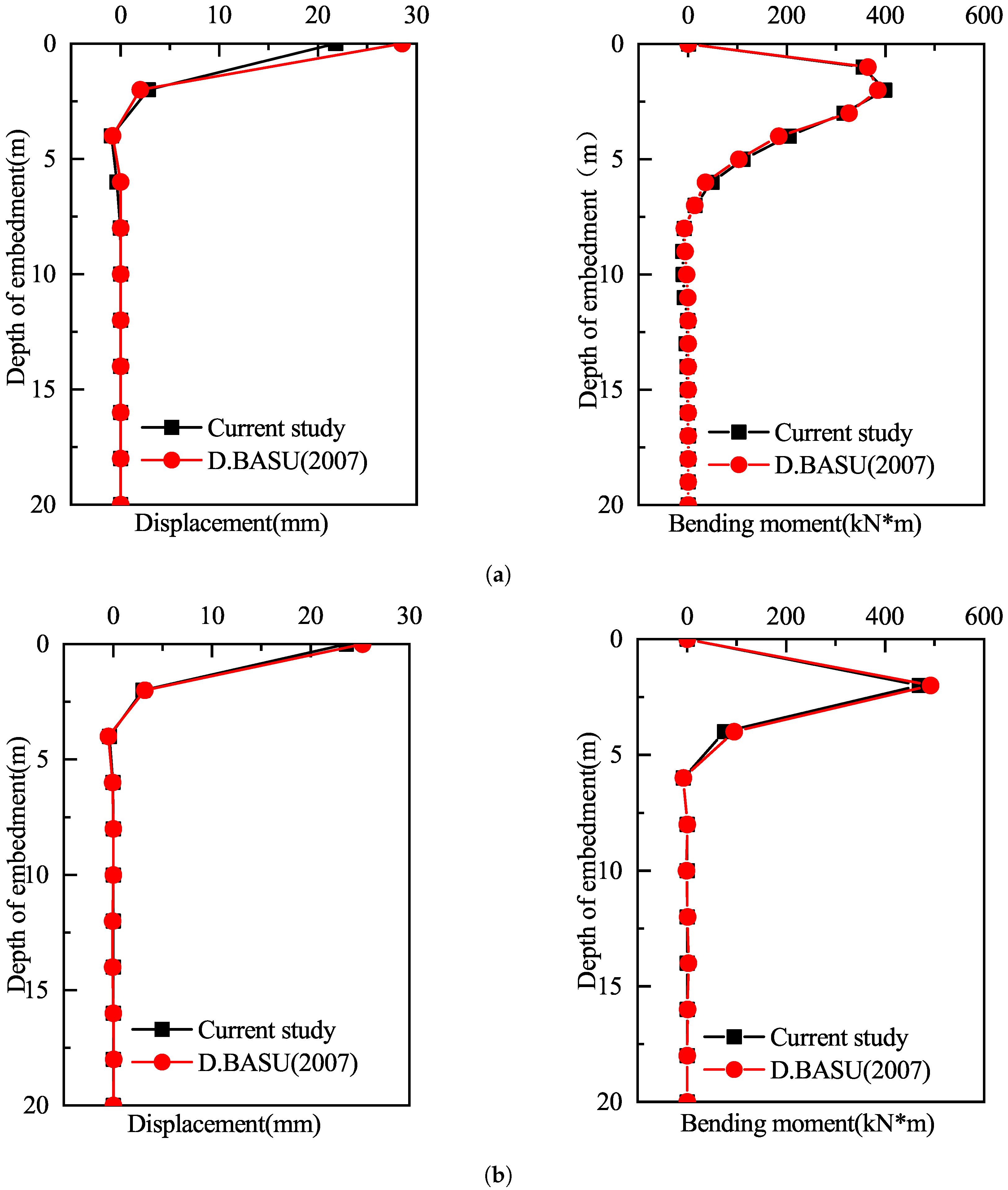
4.1. The Solution Process Verification

To verify the solution method based on the modified Vlasov foundation model and the separation of variables approach, this study simplified the layered foundation into different numbers of layers (1 layer, 2 layers, 3 layers, and 4 layers) for calculation and compared the results with those in Reference [47]. Figure 4 presents the comparison between the results obtained using the proposed method and those from Reference [47]. The results indicate that, under the same parameter conditions, the distribution trends of the pile displacement and bending moment in each layer are highly consistent, with the maximum displacement and bending moment errors controlled within 2%. This demonstrates the high accuracy and stability of the proposed method for solving the lateral load-bearing behavior of piles in complex layered foundations. The solution process was quantitatively described, with the convergence error of the iterative calculation set to ϵ = 10 3 . A stable solution was achieved after approximately 10 to 15 iterations. The numerical results show that the dimensionless parameter γ gradually approaches its theoretical value during each iteration, with a final convergence error of 0.05%. These validations confirm the applicability and feasibility of the proposed method under complex layered foundation conditions.
Furthermore, taking the case where the pile end constraint is free-fixed in the three-layer foundation as an example, the influence of the slenderness ratio λ of the pile body and the separation of the pile–soil partial contact surface on the mechanical properties of the laterally loaded long pile in the layered foundation is analyzed. To intuitively illustrate the effects of these parameters, the subsequent numerical results are converted back to their dimensional form.

4.2. Influence of Slenderness Ratio

Figure 5 illustrates the variation in deformation and internal force of the laterally loaded long pile with the slenderness ratio of the pile. The slenderness ratio of the pile is a key parameter affecting the lateral load-bearing performance of the pile. In this study, the slenderness ratio λ was taken as 20, 25, and 40 to analyze its effects on pile deformation and internal forces. The results show that pile head displacement increases nonlinearly with an increasing slenderness ratio. When λ = 20 , the pile head displacement is 2.5 mm; when λ = 25 , the displacement increases to 3.4 mm, an increment of approximately 36%; and when λ = 40 , the displacement significantly increases to 6.0 mm, representing an increment of approximately 140% compared to λ = 20 .
At the same time, the maximum bending moment decreases as the slenderness ratio increases, and its location gradually shifts upward along the pile shaft. When λ = 20 , the maximum bending moment is 1577.6 kN·m, located at 0.4 L of the pile length; when λ = 25 , the maximum bending moment decreases to 1221.3 kN·m and shifts upward to 0.3 L; and when λ = 40 , the maximum bending moment reduces to 648.6 kN·m and further shifts upward to 0.2 L. The distribution of negative shear force shows an opposite trend to that of the bending moment, decreasing with the increase in slenderness ratio while also moving upward along the pile shaft. This indicates that an increasing slenderness ratio leads to a significant increase in pile head deformation, while the internal forces in the pile decrease, resulting in reduced flexural stiffness. In practical engineering, it is necessary to comprehensively consider the reasonable matching of pile length and stiffness to ensure that pile deformation and internal forces remain within acceptable limits.

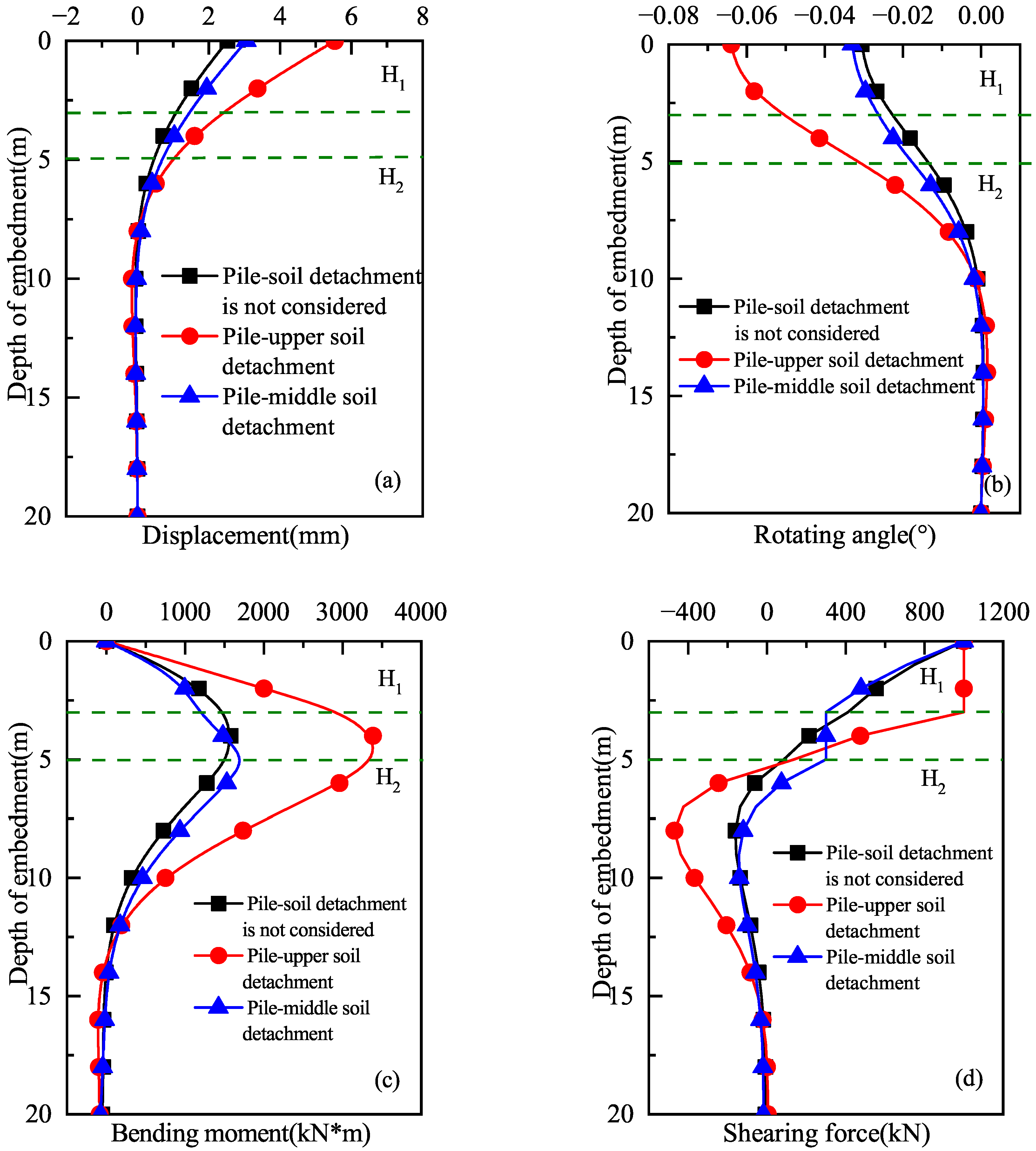
4.3. Influence of Pile–Soil Contact Surface Detachment

When the slenderness ratio of the pile is 20, Figure 6 illustrates the deformation and internal force of the laterally loaded long pile in the layered foundation under different pile–soil contact surface properties. To analyze the effect of pile–soil contact surface separation on the mechanical properties of the pile, three conditions were considered: (1) no contact surface separation: the pile maintains full interaction with the surrounding soil throughout its length; (2) complete separation of the pile–upper soil contact surface: in this case, the contact surface between the pile and the upper soil layer is fully separated, simulating a detachment at the pile top; (3) complete separation of the pile–middle soil contact surface: for this condition, only the second soil layer (midsection of the pile) experiences complete separation, simulating detachment at the middle of the pile, no contact surface separation, complete separation of the pile–upper soil contact surface, and complete separation of the pile–middle soil contact surface. The results show that the separation of the pile–upper soil contact surface has the most significant impact on the mechanical properties of the pile. The pile head displacement increases from 2.5 mm to 5.0 mm, an increment of approximately 100%; the pile head rotation increases by 2 times; the maximum bending moment increases from 1577.6 kN·m to 3155.2 kN·m; and the negative shear force increases by 3 times. In comparison, the separation of the pile–middle soil contact surface has a smaller effect, with pile head displacement increasing to 3.1 mm, an increment of approximately 24%; the maximum bending moment increases by only 13%; and the negative shear force rapidly decreases to near zero. These results indicate that the separation of the pile–upper soil contact surface causes the pile to lose critical support, leading to a significant increase in pile head deformation and a rapid increase in internal forces. On the other hand, the separation of the middle soil contact surface mainly affects the distribution of internal forces in the middle region of the pile but has a smaller effect on pile head deformation. Therefore, in practical engineering, particular attention should be given to monitoring and controlling the contact state between the pile and the upper soil layer to prevent contact surface separation from causing a decline in pile performance.

5. Conclusions

Based on the modified Vlasov foundation model, the displacement and internal force of laterally loaded long piles in layered foundations are obtained by using the separation variable method. Through numerical calculation, the influence of the slenderness ratio of the pile and the detachment of the pile–soil contact surface on the lateral loading performance of the pile foundation is analyzed. The main conclusions are as follows:
(1)
As the slenderness ratio of the pile increases, the flexibility of the pile also increases, resulting in significant growth in lateral deformation, while the maximum bending moment and maximum shear force decrease. In this study, quantitative calculations were performed to obtain the variation patterns of pile head displacement, rotation angle, and internal forces at different slenderness ratios. The results can provide a reference for pile foundation design under similar conditions.
(2)
When detachment occurs at the interface between the upper soil layer and the pile, the pile head displacement and rotation angle increase by approximately 2 times, and the maximum bending moment of the pile significantly increases, with the increase in negative shear force reaching approximately 3 times. Therefore, the support provided by the upper soil layer is crucial for the rigidity of the pile foundation. Special attention should be paid to this factor during design, and measures such as improving the soil layer can be taken to mitigate the adverse effects caused by detachment.
(3)
When detachment occurs at the interface between the middle soil layer and the pile, the increase in the pile head displacement and maximum bending moment is less than 25 %, while the maximum negative shear force decreases significantly. Compared to detachment at the upper soil layer, detachment at the middle soil layer has a smaller impact on the performance of the pile foundation.
This study conducted a precise numerical analysis to quantify the variation patterns of pile foundation stress and deformation under different contact conditions. It emphasized the significant impact of local detachment at the pile–soil interface on the pile head displacement, bending moment, and shear force, offering accurate results and theoretical support for engineering practice. However, only two ideal conditions, complete contact and full detachment, were considered, without accounting for the gradual weakening of the pile–soil interface or its correlation with deformation and soil parameters. Further research is needed to explore the lateral loading performance of long piles in layered foundations, considering interface weakening effects.

Author Contributions

Methodology, F.L. and J.M.; software, D.L.; validation, F.L. and D.L.; formal analysis, J.M.; writing—original draft preparation, F.L. and D.L.; supervision, J.M. and D.L. All authors have read and agreed to the published version of the manuscript.

Funding

This work was funded by the National Natural Science Foundation of China (Grant No. 11502072), and the Henan Province Higher Education Young Backbone Teachers Training Program (Grant No. 2019GGJS076), and the Research and Development of Decision-Making Model and Software for TBM Excavation and Support Parameter Optimization in High Geostress Soft Rock Tunnels (Grant No. 242102220037).

Institutional Review Board Statement

Not applicable.

Informed Consent Statement

Not applicable.

Data Availability Statement

Data is contained within the article.

Acknowledgments

We sincerely thank all the reviewers and editors for their professional comments and suggestions regarding this manuscript.

Conflicts of Interest

The authors declare no conflicts of interest.

References

  1. Kong, D.; Deng, M.; Zhao, Z. Seismic Interaction Characteristics of an Inclined Straight Alternating Pile Group-Soil in Liquefied Ground. Int. J. Geomech. 2019, 2019, 3758286. [Google Scholar] [CrossRef]
  2. Hemel, M.J.; Korff, M.; Peters, D.J. Analytical Model for Laterally Loaded Pile Groups in Layered Sloping Soil. Int. J. Geomech. 2022, 22, 123–145. [Google Scholar] [CrossRef]
  3. Heidari, B.; Garakani, A.A.; Jozani, S.M.; Tari, P.H. Energy Piles under Lateral Loading: Analytical and Numerical Investigations. Renew. Energy 2022, 16, 234–249. [Google Scholar] [CrossRef]
  4. Zhang, C.; Zhang, X.; Huang, M.; Tang, H. Responses of Caisson-Piles Foundations to Long-Term Cyclic Lateral Load and Scouring. Soil Dyn. Earthq. Eng. 2019, 119, 62–74. [Google Scholar] [CrossRef]
  5. McCarron, W.O. Efficient Analysis of Cyclic Laterally Loaded Piles. Results Eng. 2021, 10, 100213. [Google Scholar] [CrossRef]
  6. Pesicka, B.; Stone, L.J.; O’Neill, T. Case Study: Lateral Pile Testing for Seismic Design in Unexpected Soil Conditions. Proc. Int. Conf. Geotech. 2022, 11, 439–451. [Google Scholar] [CrossRef]
  7. Basack, S.; Karami, M.; Karakouzian, M. Pile-Soil Interaction under Cyclic Lateral Load in Loose Sand: Experimental and Numerical Evaluations. Soil Dyn. Earthq. Eng. 2022, 162, 107439. [Google Scholar] [CrossRef]
  8. Keawsawasvong, S.; Ukritchon, B. Failure Modes of Laterally Loaded Piles under Combined Horizontal Load and Moment Considering Overburden Stress Factors. Geotech. Geol. Eng. 2020, 38, 4253–4267. [Google Scholar] [CrossRef]
  9. Houda, G.; Tayeb, B.; Yahiaoui, D. Key Parameters Influencing Performance and Failure Modes for Interaction Soil–Pile–Structure System under Lateral Loading. Asian J. Civ. Eng. 2018, 19, 355–373. [Google Scholar] [CrossRef]
  10. Poulos, H.G. Pile behaviour—Theory and application. Géotechnique 1989, 39, 365–415. [Google Scholar] [CrossRef]
  11. Dai, M.; Zhou, Y.D.; Zhang, T. Recent researches on soil-pile interaction. J. Hohai Univ. (Nat. Sci.) 2006, 34, 568–571. [Google Scholar]
  12. Yang, Y.; Gao, X.; Wu, W.; Xing, K. A simplified elastoplastic method for laterally loaded single pile with large displacement. Rock Soil Mech. 2020, 41, 95–102. [Google Scholar] [CrossRef]
  13. Das, Y.C.; Sargand, S.M. Forced vibrations of laterally loaded piles. Int. J. Solids Struct. 1999, 36, 4975–4989. [Google Scholar] [CrossRef]
  14. Liu, H.L. Numerical solution of laterally loaded cast-in-place concrete large diameter pipe pile installed in multi-layered soil. Rock Soil Mech. 2010, 31, 1638–1644. [Google Scholar] [CrossRef]
  15. Fang, T.; Huang, M. Deformation and Load-Bearing Characteristics of Step-Tapered Piles in Clay under Lateral Load. Int. J. Geomech. 2019, 18, 456–478. [Google Scholar] [CrossRef]
  16. Dahal, B.K.; Regmi, S.; Paudyal, K.; Dahal, D.; KC, D. Enhancing Deep Excavation Optimization: Selection of an Appropriate Constitutive Model. CivilEng 2024, 5, 785–800. [Google Scholar] [CrossRef]
  17. Luan, L.; Liu, Y.; Li, Y. Numerical Simulation for the Soil-Pile-Structure Interaction under Seismic Loading. Int. J. Geomech. 2015, 2015, 959581. [Google Scholar] [CrossRef]
  18. Nguyen, Q.V.; Fatahi, B. Influence of Size and Load-Bearing Mechanism of Piles on Seismic Performance of Buildings Considering Soil–Pile–Structure Interaction. Int. J. Geomech. 2017, 17, 04017007. [Google Scholar] [CrossRef]
  19. Ma, J.; Han, S.; Gao, X.; Li, D.; Guo, Y.; Liu, Q. Dynamic Lateral Response of the Partially-Embedded Single Piles in Layered Soil. Appl. Sci. 2022, 12, 1504. [Google Scholar] [CrossRef]
  20. Zhan-Fang, H.; Bai, X.H.; Yin, C.; Liu, Y.Q. Numerical analysis for the vertical bearing capacity of composite pile foundation system in liquefiable soil under sine wave vibration. PLoS ONE 2021, 16, e0248502. [Google Scholar] [CrossRef]
  21. Chandaluri, V.K.; Sawant, V. Influence of sloping ground on lateral load capacity of single piles in clayey soil. Geomech. Geoeng. 2020, 15, 312–324. [Google Scholar] [CrossRef]
  22. Weaver, T.; Chittoori, B. Influence of Limited Soil Improvement on Lateral Pile Stiffness. Proc. Int. Conf. Geotech. 2007, 9, 409–416. [Google Scholar] [CrossRef]
  23. Lukpanov, R.E.; Yenkebayev, S.B.; Tsigulyov, D.V. Assessment of the bearing capacity of piles in soil, determined by static and dynamic load tests. Eng. J. Satbayev Univ. 2021, 143, 252–260. [Google Scholar] [CrossRef]
  24. Tiutkin, O.; Radkevych, A.; Dubinchyk, O.; Kharchenko, V. Parametric analysis of a strain state of a soil base strengthened with vertical elements. Min. Miner. Depos. 2024, 18, 104–112. [Google Scholar] [CrossRef]
  25. Arshad, M.; O’Kelly, B.C. Model Studies on Monopile Behavior under Long-Term Repeated Lateral Loading. J. Geotech. Geoenviron. Eng. 2022, 148, 039. [Google Scholar] [CrossRef]
  26. Zhang, L.; Jiao, D. Response analysis for slightly inclined single pile undergoing vertical and lateral loads with restraint of pile head. Chin. J. Appl. Mech. 2018, 35, 583–589. [Google Scholar]
  27. Xiong, H.; Jiang, Y.F.; Yu, R.X. Lateral vibration impedance of piles embedded in layered soil based on Laplace transform. Rock Soil Mech. 2018, 39, 1091–1097. [Google Scholar] [CrossRef]
  28. Su, A.; Zhang, M.; Shang, W.; Wang, Q. Transient Horizontal Response of a Pipe Pile in Saturated Soil with a Flexible Support at the Pile Head. Appl. Sci. 2025, 15, 682. [Google Scholar] [CrossRef]
  29. Li, H.; Liu, S.; Tong, L.; Xu, X. Investigating the Resonance Compaction Effect on Laterally Loaded Piles in Layered Soil. Eng. Geol. 2018, 246, 1–11. [Google Scholar] [CrossRef]
  30. Kavitha, P.E.; Beena, K.S.; Narayanan, K.P. A Review on Soil–Structure Interaction Analysis of Laterally Loaded Piles. Innov. Infrastruct. Solut. 2016, 1, 14. [Google Scholar] [CrossRef]
  31. Kim, Y.; Jeong, S. Analysis of Soil Resistance on Laterally Loaded Piles Based on 3D Soil–Pile Interaction. Comput. Geotech. 2011, 38, 248–257. [Google Scholar] [CrossRef]
  32. Zhu, M.X.; Gong, W.M.; He, X.Y. Transfer matrix solutions for responses of laterally loaded piles in multilayered soil deposits. Chin. J. Geotech. Eng. 2015, 37 (Suppl. 2), 46–50. [Google Scholar]
  33. Gupta, B.K.; Basu, D. Analysis of laterally loaded short and long piles in multilayered heterogeneous elastic soil. Soils Found. 2017, 57, 92–110. [Google Scholar] [CrossRef]
  34. Zhang, L.; Ou, Q.; Zhou, S.; Zhao, M. Semi-analytical solutions for vertically and laterally loaded piles in multilayered soil deposits. Environ. Earth Sci. 2018, 77, 51–64. [Google Scholar] [CrossRef]
  35. Dai, Z.H.; Chen, L.J. Two numerical solutions of laterally loaded piles installed in multi-layered soils by m method. Chin. J. Geotech. Eng. 2007, 29, 690–696. [Google Scholar]
  36. Zhang, L. Nonlinear analysis of laterally loaded rigid piles in cohesionless soil. Comput. Geotech. 2009, 36, 718–724. [Google Scholar] [CrossRef]
  37. Basar, E.E.; Celik, D.; Uzundurukan, S.; Findik, M. Investigation of structural behavior of piles in liquefiable cohesionless soils. Geomechanics 2022, 23, 89–98. [Google Scholar] [CrossRef]
  38. Yang, J.B.; Zhong, Z.X. Research on load transfer mechanism of super-long pile. Chin. J. Geotech. Eng. 1998, 20, 111–115. [Google Scholar]
  39. Jiang, J.P.; Chen, W.J.; Yang, S. Impacts of local scour on lateral bearing behavior of partially embedded single piles. Hydro-Sci. Eng. 2017, 3, 64–70. [Google Scholar] [CrossRef]
  40. Bao, T.; Liu, Z. Evaluation of Winkler Model and Pasternak Model for Dynamic Soil-Structure Interaction Analysis of Structures Partially Embedded in Soils. Int. J. Geomech. 2020, 20, 04019167. [Google Scholar] [CrossRef]
  41. Wang, Y.; Orense, R.P. Numerical investigation of inclined piles under liquefaction-induced lateral spreading. Geotechnics 2023, 3, 19. [Google Scholar] [CrossRef]
  42. Richter, S.; Cudmani, R.; Slominski, C. The behavior of a spread footing over reinforced ground with gravel interface during a strong earthquake. Geotech. Res. 2011, 8, 96–104. [Google Scholar] [CrossRef]
  43. Das, Y.C.; Vallabhan, C.V.G. Parametric study of beams on elastic foundations. J. Struct. Eng. 1988, 114, 2072–2088. [Google Scholar] [CrossRef]
  44. Reddy, J.N. Energy and Variational Methods in Applied Mechanics; Wiley: Hoboken, NJ, USA, 1984. [Google Scholar]
  45. Sun, K. Laterally loaded pile in elastic media. J. Geotech. Eng. 1994, 120, 1324–1344. [Google Scholar] [CrossRef]
  46. Ma, J.J.; Liu, Q.J.; Zhao, Y.Y. Stability of beams on modified Vlasov foundation subjected to lateral loads acting on the ends. Chin. J. Geotech. Eng. 2008, 30, 850–854. [Google Scholar]
  47. Basu, D.; Salgado, R. Elastic analysis of laterally loaded pile in multi-layered soil. Geomech. Geoeng. 2007, 2, 183–196. [Google Scholar] [CrossRef]
Figure 1. Laterally loaded long pile in layered foundation.
Applsci 15 01759 g001
Figure 2. Schematic diagram of pile–soil system displacement and soil stress around pile. (a) Displacement of pile–soil system. (b) Stress diagram of soil around pile.
Applsci 15 01759 g002
Figure 3. Computational flow chart.
Applsci 15 01759 g003
Figure 4. Comparison of the numerical results of the present study with those of Reference [47]. (a) Pile foundation in homogeneous soil. (b) Pile foundation in layered soil.
Applsci 15 01759 g004
Figure 5. Effect of parameter λ on the mechanical characteristics of a laterally loaded long pile. (a) The displacement. (b) The rotating angle. (c) The bending moment. (d) The shearing force.
Applsci 15 01759 g005
Figure 6. Effect of the contact surface separation on the mechanical characteristics of a laterally loaded long pile. (a) The displacement. (b) The rotating angle. (c) The bending moment. (d) The shearing force.
Applsci 15 01759 g006
Table 1. Solution function.
Parameter k i < t i 2 k i > t i 2
a i t i + t i 2 k i 1 / 2 ( k i + t i )
b i t i t i 2 k i 1 / 2 ( k i t i )
f i 1 sinh a i z sinh a i z cos b i z
f i 2 cosh a i z cosh a i z cos b i z
f i 3 sinh b i z cosh a i z sin b i z
f i 4 cosh b i z sinh a i z sin b i z
Table 2. Physical parameters of the pile and layered foundation.
ParameterPhysical MeaningValueUnit
E p Elastic modulus of pile2.5 × 104MPa
LPile length20m
ν 1 , 2 , 3 Poisson’s ratio of elastic foundation0.25
H 1 , 2 Depth of foundation3, 5m
E s 1 Elastic modulus of the first layer foundation50MPa
E s 2 Elastic modulus of the second layer foundation100MPa
E s 3 Elastic modulus of the third layer foundation200MPa
Disclaimer/Publisher’s Note: The statements, opinions and data contained in all publications are solely those of the individual author(s) and contributor(s) and not of MDPI and/or the editor(s). MDPI and/or the editor(s) disclaim responsibility for any injury to people or property resulting from any ideas, methods, instructions or products referred to in the content.

