Article

Solution for Active and Passive Earth Pressure on Rigid Retaining Walls with Narrow Backfill

1
School of Civil Engineering and Architecture, Xi’an University of Technology, Xi’an 710048, China
2
State Key Laboratory of Eco-hydraulics in Northwest Arid Region, Xi’an University of Technology, Xi’an 710048, China
3
School of Civil Engineering and Architecture, University of Jinan, Jinan 250024, China
*
Author to whom correspondence should be addressed.
Appl. Sci. 2025, 15(4), 1750; https://doi.org/10.3390/app15041750
Submission received: 5 January 2025 / Revised: 1 February 2025 / Accepted: 6 February 2025 / Published: 9 February 2025

Abstract

:
For a retaining wall adjacent to rock or rigid structures, existing model test results indicate that the slip soil in the limit state can be approximated as a trapezoidal slip wedge. Based on the static equilibrium condition of the slip wedge, a calculation method for active and passive earth pressures is proposed that considers the effect of backfill width through extreme value analysis. As the backfill width increases, the trapezoidal slip wedge transitions to a triangular slip wedge, introducing a critical width to distinguish between finite and semi-infinite soil conditions. For cohesionless soils, the proposed method converges to Coulomb theory at the critical width; when the backfill is clay, the critical width exceeds the width of Coulomb’s triangular slip wedge due to the stabilizing contribution of cohesion. Parameter analysis reveals that with increasing backfill width, the active earth pressure of cohesionless soil follows a non-linear upward trend, whereas the passive earth pressure decays exponentially. For clay, the active earth pressure initially increases with backfill width and then decreases, whereas the passive earth pressure first decays exponentially and then exhibits a slight increase. Variations in the friction angle significantly affect both active and passive earth pressures, while cohesion mainly influences active earth pressure, and wall-soil friction angle exerts a stronger impact on passive earth pressure. The effectiveness of the proposed method is verified by comparison with results from model tests and numerical simulations.

1. Introduction

The traditional Rankine theory is predicated on the assumption that all points of the soil behind the wall are in the limit equilibrium state. Coulomb theory posits that a triangular slip wedge forms when the soil behind the wall fails. With the advancement of modern infrastructure, retaining structures are increasingly situated near pre-existing structures or rock mass [1,2]. Under finite backfill conditions, the restricted backfill width prevents full development of the slip surface, resulting in a significant divergence in earth pressure from semi-infinite soil scenarios, as evidenced by prior studies [3,4]. Therefore, it is imperative to develop earth pressure calculation methods that incorporate the impact of backfill width.
To investigate the earth pressure behind the retaining structures under finite backfill width conditions, Frydman and Keissar [5] and Take and Valsangkar [6] conducted model tests. Their results were significantly different from the theoretical predictions of earth pressure in semi-infinite soil. Moreover, the arching effect phenomenon [7,8] also affects the distribution of earth pressure. Yang and Tang [9] additionally examined the impact of the retaining wall displacement pattern on earth pressure under finite backfill width conditions. As demonstrated by Yang et al. [10] through slip surface analysis in active states, the complete development of Coulomb’s theoretical triangular slip wedge is impeded by geometric constraints imposed by finite backfill dimensions. Similarly, field measurements by Hu et al. [11] demonstrated that the active earth pressure under limited backfill widths is less than that predicted by Rankine theory, resulting in inherent conservatism in conventional design approaches.
The advancement of computational mechanics has created novel research avenues for investigating earth pressure mechanisms. For finite soils, Fan and Fang [12] demonstrated that the active earth pressure behind the wall is significantly lower than that in the Coulomb solution. Yang and Deng [13] conducted systematic DEM investigations elucidating the coupled influence of backfill width and soil strength parameters on the active earth pressure. Through statistical characterization of DEM simulations, Li et al. [14] classified the failure mechanisms into three categories according to the backfill width behind the wall. In cases where the backfill is cohesionless soil, Chen et al. [15,16] examined the variation pattern of the passive earth pressure in translational and rotational modes around the wall bottom through FELA analysis. Notably, their simulations revealed the progressive development of quadrilateral slip wedges. Yang et al. [17] investigated the active earth pressure of clay in the rotational mode around the wall top. Based on adaptive finite element analysis, Wang et al. [18] investigated the failure mechanism of an inverted T-shaped retaining wall in the active state. Chen et al. [19] found that the slip surface of the backfill originated from the wall heel, and its development was influenced by the backfill width behind the wall. Moreover, the slip surface curvature was found to correlate strongly with soil-structure interface friction and soil strength.
When the rock slope is adjacent to the retaining wall and its inclined surface intersects with the wall heel, Tang and Chen [20] treated the rock slope surface as the slip surface and applied the wedge element method to determine the active earth pressure distribution. For translational retaining walls with a finite backfill width, Chen et al. [21] developed a theoretical framework to calculate the active earth pressure of cohesionless soil using the limit equilibrium method. Both the geometric configuration and interfacial friction properties of the finite soil significantly affect the active earth pressure behind the wall, as demonstrated by Lin et al. [22]. Khosravi et al. [23] modeled the soil slip surface as a bilinear plane and analyzed the active earth pressures of narrow backfills through force balance analysis. In addition, the retaining wall foundation affects the earth pressure under finite backfill conditions. Chen et al. [24] observed that the slip surface develops simultaneously toward the rock surface and the ground ahead of the wall, leading to the proposal of a slip-line computational model. To distinguish finite soils from semi-infinite soils, Yang et al. [10] proposed a critical ratio of 0.5 between backfill width and wall height under an active state, while Wang et al. [25] suggested a threshold ratio of three for passive conditions, beyond which the effect of backfill width on earth pressure becomes negligible. However, the classification based on experimental results or empirical data lacks sufficient accuracy, and the influence of various parameters on the critical width is not considered.
The deformation mode of flexible retaining walls differs significantly from that of rigid retaining walls. Hu et al. [26] developed a computational approach for active earth pressure under drum deformation by refining the horizontal layer analysis method, but this methodology was restricted to cohesionless soils. Li et al. [27] quantified the combined influence of horizontal shear stresses and the soil arching on passive earth pressure using the arched differential element method. For the rotation mode around the wall bottom, Wang et al. [28] investigated the effect of the backfill width on the active earth pressure using the inclined thin-layer element method. Fu et al. [29] investigated active earth pressure distributions in unsaturated soil walls using the thin-layer element method. Liu and Kong [30,31] examined the coupled effects of intermediate principal stress, soil arching, and unsaturated seepage on the active earth pressure under finite backfill width conditions. For retaining walls that rotate about their base, Lai et al. [32] proposed a prediction model for active earth pressure based on the arch differential element method, incorporating backfill width effects. In the case of finite backfill width, the slip surface behind the wall has a certain curvature. Huang et al. [33] characterized it as a cycloid through the wall heel. The stress deflection caused by wall-soil friction is considered by the arc-shaped minor principal stress trajectory [7], and the active earth pressure solution for cohesionless soil is obtained by the horizontal differential element method. Li et al. [34] assumed that the slip surface follows a log-spiral surface and proposed a semi-analytical method; nevertheless, its computational complexity limits practical engineering applications. The limit equilibrium method is widely employed in various earth pressure calculation scenarios [35,36], but it neglects the effect of soil dilation [37] on the results. Hu et al. [38] extended this method to cohesionless soils with finite width. The previous analysis reveals that existing studies are less relevant for clay and there is a lack of research on passive earth pressure in finite soils. Furthermore, the debate regarding the accurate definition of semi-infinite and finite soils persists and warrants further in-depth discussion.
Building upon prior research, this study hypothesizes the development of a trapezoidal slip wedge during soil failure under finite soil conditions. Cohesion is uniformly distributed along the slip surface. In the passive state, the earth pressure on both sides above the slip surface inflection point is equal. The ratio of earth pressures on the left and right lateral boundaries in the active state is called a s . By utilizing the static equilibrium condition of the slip wedge, a generalized formulation for the limit earth pressure in finite backfill was derived. As the backfill width gradually increases, the trapezoidal wedge ultimately transitions into a triangular wedge. Therefore, the width of the triangular slip wedge defined in Coulomb theory is regarded as the critical width of the finite backfill. Once the critical width is exceeded, the soil can be considered as semi-infinite. By comparing the proposed method with experimental results, the rationality of the proposed approach is demonstrated. A comprehensive parametric study further quantifies the sensitivity of limiting earth pressure to cohesion, internal friction angle, and wall-soil interface friction.

2. Theoretical Analysis

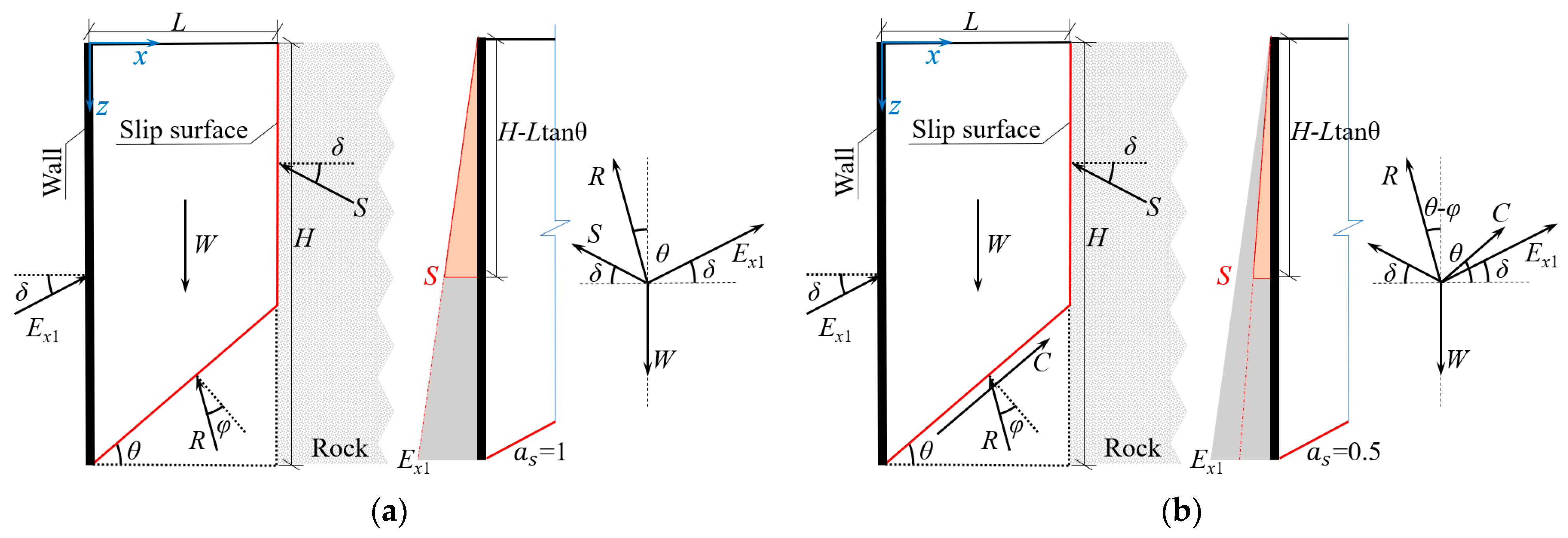
2.1. Active Limit Earth Pressure

Retaining walls adjacent to rigid geological/structural boundaries retain a finite soil with constrained lateral dimensions. In accordance with the results of previous experimental studies [32,37,38,39], this study assumes that upon the destruction of the soil behind the wall, the slip surface manifests as a folded surface, with the slip soil forming a trapezoidal wedge. The force analysis of the slip wedge in the active limit state is shown in Figure 1.
The reaction force ( E x 1 ) exerted by the retaining wall forms an angle with the horizontal direction equal to the wall-soil friction angle ( δ ). The reaction force exerted on the slip wedge by the soil beneath the slip surface is denoted as R and forms an angle with respect to the normal to the slip surface, which is the internal friction angle ( φ ). W represents the weight of the slip wedge. For clay, the cohesion ( c ) is uniformly distributed along the slip surface, generating a resultant force denoted as C that forms an angle with the horizontal direction equal to the rupture angle θ , with an effective range of (50°, 80°) in the active state.
In cohesionless soil, there is no bonding between soil particles, the soil and rock (or structure) remain in contact under the active state. Hu et al. [38] postulated that the earth pressure on both sides above the slip surface inflection point was equal, i.e., the reaction coefficient a s = 1. This conclusion is supported by the model test results of Chen et al. [40], and the force analysis for this case is presented in Figure 1a. When the backfill consists of clay, partial separation occurs between the soil and rock (or structure) under the active limit state due to cohesive bonds between soil particles. Consequently, this paper assumes that the earth pressure on the rock (or structure) above the slip surface inflection point is half of that on the left retaining wall, i.e., a s = 0.5, with the corresponding stress analysis presented in Figure 1b. To simplify the calculation, the earth pressure is assumed to be triangularly distributed. The counterforce of the rock on the slip wedge is denoted as S . The expressions of W, C , and S of the slip wedge are as follows:
S = a s E x 1 ( H L tan θ ) 2 H 2         W = γ ( H L 1 2 L 2 tan θ )         C = c L / cos θ
From the comparison of Figure 1a,b, it can be seen that the force on the slip wedge of cohesionless soil is a special case of the force on the clay slip wedge. Specifically, this occurs when the cohesion c = 0 and the reaction coefficient a s = 1. Therefore, according to the static equilibrium conditions of the clay slip wedge in the horizontal and vertical directions under the active state, Equation (2) can be obtained.
R sin ( θ φ ) + S cos δ = C cos θ + E x 1 cos δ R cos ( θ φ ) + S sin δ + C sin θ + E x 1 sin δ = W
Solving both equations in Equation (2) simultaneously yields Equation (3).
E x 1 = W H 2 tan ( θ φ ) C H 2 cos θ C H 2 sin θ tan ( θ φ ) H 2 cos δ a s ( H L tan θ ) 2 cos δ + a s ( H L tan θ ) 2 sin δ tan ( θ φ ) + H 2 sin δ tan ( θ φ )
From Equation (3), it can be seen that E x 1 is a univariate function of the rupture angle ( θ ). By setting ψ = tan θ , Equation (3) can be simplified to Equation (4).
E x 1 = A 1 ψ 2 + B 1 ψ + C 1 D 1 ψ 3 + E 1 ψ 2 + F 1 ψ + G 1
In which:
A 1 = ( 1 2 γ H 2 L 2 + c H 2 L )           B 1 = γ H 3 L + 1 2 γ H 2 L 2 tan φ C 1 = ( γ H 3 L tan φ + c H 2 L )           D 1 = a s ( L 2 sin δ L 2 cos δ tan φ ) E 1 = a s ( 2 H L cos δ tan φ 2 H L sin δ L 2 cos δ L 2 sin δ tan φ ) F 1 = ( 1 a s ) H 2 cos δ tan φ + 2 a s H L cos δ + ( 1 + a s ) H 2 sin δ + 2 a s H L sin δ tan φ G 1 = ( 1 a s ) cos δ H 2 ( 1 + a s ) H 2 sin δ tan φ
In the scenario where the soil behind the wall is in the active limit state, the resultant active earth pressure force ( E a ) on the retaining wall is the maximum of the function E x 1 ( θ ) . By analyzing numerous plots of the function E x 1 ( θ ) generated using Mathematica, it was observed that the point of maximum point within the range of the rupture angle is also the stationary point of the function. Therefore, to find the stationary point, the derivative of Equation (4) is taken, resulting in Equation (6).
d E x 1 d ψ = ( 2 A 1 ψ + B 1 ) ( D 1 ψ 3 + E 1 ψ 2 + F 1 ψ + G 1 ) ( A 1 ψ 2 + B 1 ψ + C 1 ) ( 3 D 1 ψ 2 + 2 E 1 ψ + F 1 ) ( D 1 ψ 3 + E 1 ψ 2 + F 1 ψ + G 1 ) 2
In Equations (4) and (6), parameters δ , φ , and x (tan θ ) each possess distinct significance. Within the range of rupture angle values, it can be demonstrated that the denominator of the derivative of E 1 ( θ ) remains positive. To identify the stationary point, the derivative is set to zero as expressed in Equation (7).
A 1 D 1 ψ 4 2 B 1 D 1 ψ 3 + ( A 1 F 1 B 1 E 1 3 C 1 D 1 ) ψ 2 + 2 ( A 1 G 1 C 1 E 1 ) ψ + B 1 G 1 C 1 F 1 = 0
The above equation constitutes a quartic equation with four general solutions. However, given the explicit physical significance of the rupture angle θ which must satisfy the condition θ > 0, the specific analytical expression for the rupture angle is ultimately determined as depicted in Equation (8).
θ a = arctan b 1 4 a 1 + 1 2 b 1 2 4 a 1 2 2 c 1 3 a 1 + Δ 1 1 2 b 1 2 2 a 1 2 4 c 1 3 a 1 Δ 1 + b 1 3 a 1 3 + 4 b 1 c 1 a 1 2 8 d 1 a 1 4 b 1 2 4 b 1 2 2 c 1 3 a 1 + Δ 1
The coefficients are presented in Equation (9).
a 1 = A 1 D 1 b 1 = 2 B 1 D 1 c 1 = A 1 F 1 B 1 E 1 3 C 1 D 1 d 1 = 2 A 1 G 1 2 C 1 E 1 e 1 = B 1 G 1 C 1 F 1 λ 1 = c 1 2 3 b 1 d 1 + 12 a 1 e 1 η 1 = 2 c 1 3 9 b 1 c 1 d 1 + 27 a 1 d 1 2 + 27 b 1 2 e 1 72 a 1 c 1 e 1 Δ 1 = 2 3 λ 1 3 a 1 η 1 + 4 λ 1 3 + η 1 2 3 + η 2 + 4 λ 1 3 + η 1 2 3 3 2 3 a 1
Based on the variation range of the soil parameters behind the wall, it was determined that Equation (7) typically has two imaginary and two real solutions. Among these solutions, Equation (6) exhibits opposite signs on either side of the real stagnation point, with the stationary point value exceeding zero. This stationary point coincides with the rupture angle corresponding to the maximum value of the function E x 1 ( θ ) computed using MATLAB, thereby confirming it as the maximum value point. By substituting θ a into Equation (3), the active limit earth pressure resultant force ( E a ) acting on the retaining wall can be obtained under the condition of finite backfill width.
L a = 2 H A 2 B 2 B 2 2 4 A 2 C 2 A 2 = c H ( cos δ sin δ tan φ ) ( c H tan φ + 1 2 r H 2 c H tan φ ) ( cos δ tan φ + sin δ ) B 2 = ( 1 2 r H 2 tan φ + c H ) ( 2 cos δ tan φ + 2 sin δ ) C 2 = ( 1 2 r H 2 tan φ + c H ) ( cos δ sin δ tan φ )
In this paper, the slip surface of finite soil develops as a folded surface. With increasing backfill width ( L ) behind the wall, the rupture angle ( θ ) gradually decreases, while the height at the inflection point ( L tan θ ) of the slip surface steadily increases until it coincides with the ground surface, expressed as H   = L tan θ a . This expression serves as an implicit expression of the critical width. For engineering practicality, the width of the triangular slip wedge assumed in Coulomb theory is considered the critical width ( L a ) applicable to the proposed methodology.
Notably, at the critical width, the results derived from this paper are greater than the predictions of Coulomb theory when backfill consists of clay. When the backfill consists of cohesionless soil, the critical width obtained through the proposed method matches precisely with the width of the Coulomb triangular slip wedge and degrades to Coulomb theory at the critical width.

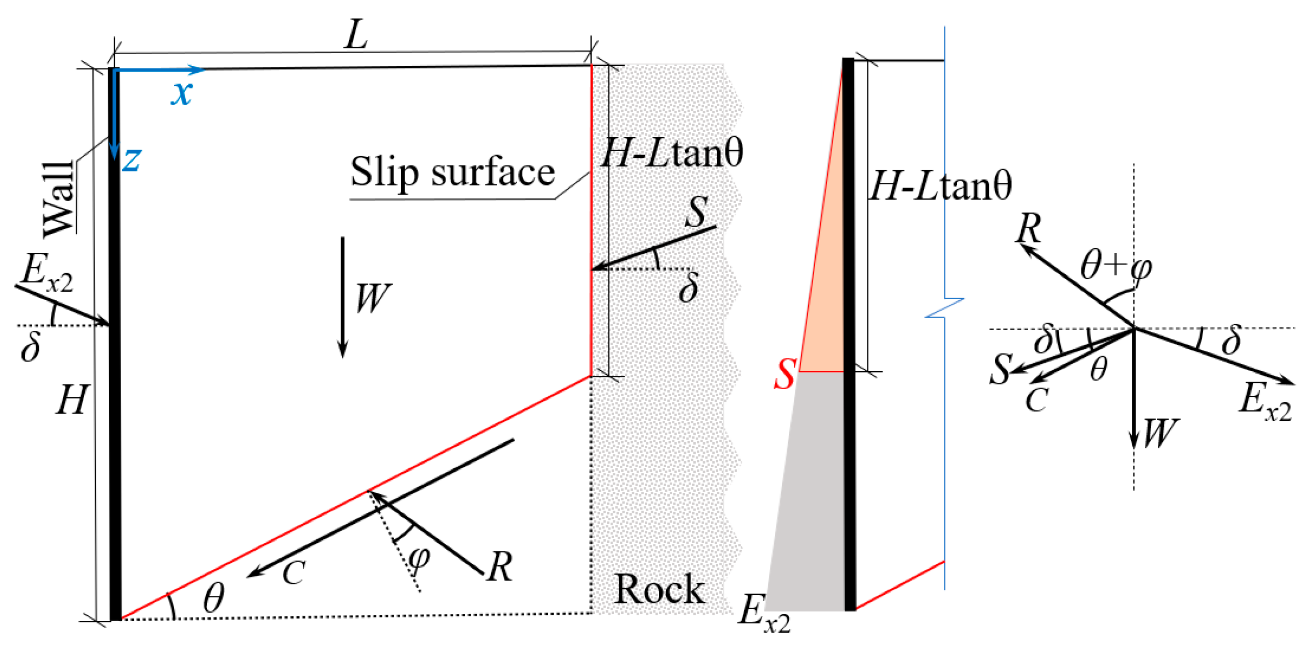
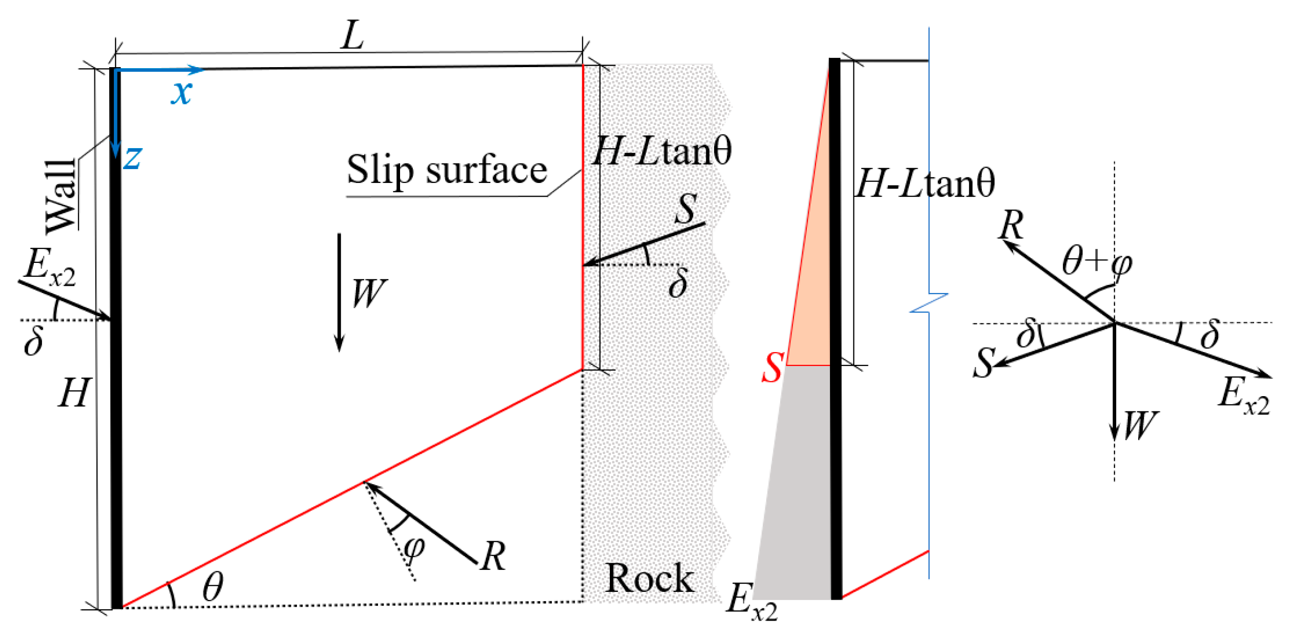
2.2. Passive Limit Earth Pressure

There are slight differences in the forces acting on the slip wedge between the passive and active states. In the passive state, where the wedge undergoes rightward movement, the rock (or structure) maintains intimate contact and interacts with the slip wedge. Consequently, the earth pressures at the same depth above the slip surface inflection point are postulated to be equal on both sides of the wedge. For computational simplification, the earth pressure is considered to follow a triangular distribution. Furthermore, the cohesion ( c ) is uniformly distributed on the slip surface. The corresponding mechanical model of the slip wedge under these conditions is shown in Figure 2.
In the schematic, E x 2 represents the resultant force on the retaining wall. Both E x 2 and the counterforce S form an angle δ (wall-soil friction angle) with the horizontal plane. The soil beneath the slip surface also exerts a counterforce ( R ) on the slip wedge, where the angle between R and the normal to the slip surface equals the internal friction angle ( φ ). The resultant force of cohesion ( C ) along the slip surface forms an angle θ (rupture angle) with the horizontal plane. In this case, the rupture angle θ is constrained within the range (10 ° , 40 ° ). The expressions for the self-weight ( W ), the resultant force of cohesion ( C ), and the counterforce ( S ) acting on the slip wedge are given in Equation (11).
W = γ ( H L 1 2 L 2 tan θ )         C = c L / cos θ         S = E x 2 ( H L tan θ ) 2 H 2
According to the static equilibrium conditions in both horizontal and vertical directions for the slip wedge under the passive state, Equation (12) is derived.
R sin ( θ + φ ) + S cos δ + C cos θ = E x 2 cos δ R cos ( θ + φ ) = S sin δ + C sin θ + W + E x 2 sin δ
The expression relating E x 2 with respect to the rupture angle θ can be derived from Equations (11) and (12), as illustrated in Equation (13).
E x 2 = H 2 c L tan θ tan ( θ + φ ) + H 2 W tan ( θ + φ ) + H 2 S cos δ + H 2 c L H 2 cos δ ( H L tan θ ) 2 cos δ ( H L tan θ ) 2 sin δ tan ( θ + φ ) H 2 sin δ tan ( θ + φ )
Equation (13) explicitly demonstrates that E x 2 is a unary function of the rupture angle θ . By introducing the substitution ψ = tan θ , it simplifies this to Equation (14).
E x 2 = A 3 ψ 2 + B 3 ψ + C 3 D 3 ψ 3 + E 3 ψ 2 + F 3 ψ + G 3 A 3 = H 2 c L 1 2 γ H 2 L 2 B 3 = γ H 3 L 1 2 γ H 2 L 2 tan φ C 3 = γ H 3 L tan φ + H 2 c L D 3 = L 2 ( cos δ tan φ sin δ ) E 3 = 2 H L ( sin δ cos δ tan φ ) L 2 ( sin δ tan φ + cos δ ) F 3 = 2 H L ( cos δ + sin δ tan φ ) 2 H 2 sin δ G 3 = 2 H 2 sin δ tan φ
For a given soil, parameters A 5 through G 5 are constant in the function. The passive limit earth pressure resultant force ( E p ) corresponds to the minimum value of E x 2 ( θ ) within the defined parameter range. The minimum value should also be the stationary point of E x 2 ( θ ) . Thus, taking the derivative of Equation (14) yields Equation (15).
d E x 2 d ψ = ( 2 A 3 ψ + B 3 ) ( D 3 ψ 3 + E 3 ψ 2 + F 3 ψ + G 3 ) ( A 3 ψ 2 + B 3 ψ + C 3 ) ( 3 D 3 ψ 2 + 2 E 3 ψ + F 3 ) D 3 ψ 3 + E 3 ψ 2 + F 3 ψ + G 3 2
The passive limit earth pressure behind the retaining wall definitely exists and its corresponding rupture angle is the stationary point of E x 2 ( θ ) within the range of θ . Furthermore, the denominator in Equation (15) is consistently greater than or equal to 0. By setting the derivative equal to zero and rearranging, Equation (16) is derived.
A 3 D 3 ψ 4 2 B 3 D 3 ψ 3 + ( A 3 F 3 B 3 E 3 3 C 3 D 3 ) ψ 2 + ( 2 A 3 G 3 2 C 3 E 3 ) ψ + ( B 3 G 3 C 3 F 3 ) = 0
Equation (16) constitutes a unary quartic equation with four general solutions. Based on the range of soil parameters, these solutions typically include two imaginary roots and two real roots. Within the valid range of the rupture angle, the stationary point is presented in Equation (17). This stationary point is rigorously validated to be consistent with the rupture angle corresponding to the minimum value obtained by solving for E x 2 ( θ ) in MATLAB.
θ p = arctan b 2 4 a 2 1 2 b 2 2 4 a 2 2 2 c 2 3 a 2 + Δ + 1 2 b 2 2 2 a 2 2 4 c 2 3 a 2 Δ b 2 3 a 2 3 + 4 b 2 c 2 a 2 2 8 d 2 a 2 4 b 2 2 4 a 2 2 2 c 2 3 a 2 + Δ
In which:
a 2 = A 3 D 3           b 2 = 2 B 3 D 3           c 2 = A 3 F 3 B 3 E 3 3 C 3 D 3 d 2 = 2 A 3 G 3 2 C 3 E 3           e 2 = B 3 G 3 C 3 F 3           λ 2 = c 2 2 3 b 2 d 2 + 12 a 2 e 2 η 2 = 2 c 2 3 9 b 2 c 2 d 2 + 27 a 2 d 2 + 27 b 2 2 e 2 72 a 2 c 2 e 2 Δ 2 = 2 3 λ 2 3 a 2 η 2 + 4 λ 2 3 + η 2 2 3 + η 2 + 4 λ 2 3 + η 2 2 3 3 2 3 a 2
By substituting θ p into Equation (13), the passive limit earth pressure resultant force on the retaining wall under finite soil conditions can be determined.
As the backfill width behind the retaining wall ( L ) increases, the height of the inflection points on the slip surface ( L tan θ ) increases synchronously until it aligns with the ground surface. At this point, the slip wedge transforms into a triangular wedge, with its width corresponding to the critical width. The specific expression is H = L tan θ p , but this represents an implicit expression of the critical width. For ease of application, this study adopts the width of the triangular wedge in Coulomb theory as the critical width ( L p ).
L p = 2 H A 4 B 4 + B 4 2 4 A 4 C 4 A 4 = 4 c H ( cos δ sin δ tan φ ) + 2 γ H 2 ( cos δ tan φ + sin δ ) B 4 = 4 ( γ H 2 tan φ + 2 c H ) ( cos δ tan φ + sin δ ) C 4 = 2 ( cos δ sin δ tan φ ) ( γ H 2 tan φ + 2 c H )
In the case where the backfill behind the wall comprises cohesionless soil ( c = 0), the force on the slip wedge in the passive state is depicted in Figure 3. Similarly, this scenario can be considered a special case of the force on the clay slip wedge.
It should be noted that when the backfill width behind the wall equals the critical width, the results obtained using the proposed method are consistent with the Coulomb result for cohesionless soil. However, for clay, the results obtained in this paper are slightly greater than the Coulomb results at the critical width.

2.3. Earth Pressure Distribution

According to the study of Zhang et al. [41], the change in soil stress behind the retaining wall is closely related to the wall displacement and soil depth. The expression for the earth pressure resultant force behind the wall is shown in Equation (20).
E a ( p ) = F Σ x = 0 h σ x d z = 1 2 K 0 γ h 2 + 1 1 μ 2 0 h E t ε x d z
E t = 1 R f ( 1 sin φ ) ( σ 1 σ 3 ) 2 c cos φ + 2 σ 3 sin φ 2 K P a ( σ 3 P a ) n
In this context, E t represents the tangent modulus in the Duncan model; R f represents the failure ratio; K denotes the modulus parameter; P a signifies the atmospheric pressure; n is the dimensionless index; μ is the Poisson’s ratio and K 0 is the coefficient of earth pressure at rest. The limit earth pressure resultant force is derived from Equations (3) and (13) and then inserted into Equation (20) to ascertain the limit strain ε x m a x .
The displacement mode significantly impacts the displacement distribution of the retaining wall. In the translational mode, the soil deformation behind the wall is independent of the burial depth ( z ), represented by ε x   = ε x m a x . In the rotation mode around the wall bottom, the maximum soil deformation occurs at the wall top. The deformation gradually decreases with increasing depth ( z ) and approaches zero at the wall bottom. This distribution function is described as ε x = z ε x m a x / H . In the rotation mode around the wall top, the maximum soil deformation occurs at the wall bottom, while no deformation is observed at the top. The distribution function is expressed as ε x = (1− H / z ) ε x m a x . By substituting these distribution functions of ε x into Equation (22), the distribution function of earth pressure on the retaining wall in the limit state can be obtained.
σ x = μ 1 μ σ z + E t ε x 1 μ 2

3. Experimental Verification

3.1. Model Test

To investigate the influence of the backfill width on the active earth pressure, Hu et al. [26] conducted a model test under rotation mode around the wall bottom (RB mode). The retaining wall had a vertical back face with a retained soil height of 0.5m. The backfill consists of cohesionless soil with an internal friction angle of 36.5° and a unit weight of 15 kN/m3. Additionally, the wall-soil friction angle is 24.3° and Poisson’s ratio is taken as 0.23. The backfill widths were set to 0.1 m, 0.15 m, 0.2 m, 0.25 m, and 0.35 m. In the Duncan model, the failure ratio ( R f ) is set to 0.75, the modulus parameter ( K ) is set to 410, and the dimensionless index ( n ) is set to 0.58. The comparison between the proposed method and experimental results is depicted in Figure 4a.
In this mode, the wall displacement gradually decreases with increasing burial depth. The soil modulus is closely correlated with the confining pressure. Since the confining pressure at the wall top is zero, its modulus also becomes zero, resulting in a negligible influence of wall displacement on earth pressure in this region. As the burial depth increases, the soil modulus progressively increases, while the soil at the wall bottom remains undeformed. Consequently, the earth pressure at the bottom maintains a constant value.
With the gradual increase of backfill width ( L ) behind the wall, the earth pressure also increases. When L > 0.2 m, the impact on the earth pressure decreases rapidly. At L = 0.25 m, the backfill width exerts almost no effect on the earth pressure, approaching the critical width ( L a = 0.29 m) calculated by Equation (10). When L   = L a , the results from this study align with the Coulomb results. By integrating the model test results along the soil depth, the earth pressure resultant force behind the wall can be determined. This result is subsequently compared with those from Equations (3) and (8), as shown in Figure 4b. The Pearson correlation coefficient between the two is 0.993, and the trends are generally consistent; however, the results of this paper are slightly lower than the experimental results. The errors of the two gradually decrease as the backfill width decreases, ranging from a maximum of 18.45% to a minimum of 8.29%, indicating good numerical consistency.
Ying et al. [42] conducted model tests to investigate the influence of the backfill width on the passive earth pressure under translational mode. In this experiment, the retained soil height was 0.525 m with a vertical wall back face. The backfill consisted of cohesionless soil with an internal friction angle of 35°, a unit weight of 14.6 kN/m3, a wall-soil friction angle of 16.57°, and Poisson’s ratio was 0.24. The backfill widths were set to 0.56 m, 0.7 m, 1.05 m, 1.4 m, and 1.75 m. In the Duncan model, the failure ratio ( R f ) was set to 0.78, the modulus parameter ( K ) was set to 390, and the dimensionless index ( n ) was set to 0.58. Comparative results between the two approaches under the limit state are shown in Figure 5a.
In translational mode, the soil deformation is independent of the burial depth. The earth pressure at the top of the wall remains unchanged, as the confining pressure is zero, resulting in a tangent modulus of zero. As the burial depth increases, the confining pressure and the tangential modulus of the soil increase progressively, leading to a non-linear rise in earth pressure. In the actual project, the stiffness of the retaining wall is considerably greater than that of the fill behind it. When the retaining wall displaces, the earth pressure behind it generates a stress concentration, leading to the development of the soil arching effect [43]. Moreover, as the width of the soil behind the wall decreases, the earth pressure in the passive limit state increases, further intensifying the stress concentration and consequently increasing the area of failure of the backfill. The limit equilibrium method did not account for the effect of soil dilation on the results, resulting in a significant error between the two, which will be addressed in future research. As the backfill width increases, the earth pressure decreases, and the stress concentration diminishes. Therefore, when H / L > 1, the results presented in this paper rapidly converge toward experimental values. The Pearson correlation coefficient between the two datasets is 0.975, with maximum and minimum errors of 41.1% and 7.9%, respectively. The fundamentally consistent variation trends validate the applicability of the proposed method.
The previous discussion is a comparative analysis in the case of cohesionless soil behind the wall. Conducting model tests for clay proves challenging due to the inherent characteristics of the material, resulting in a scarcity of existing experimental studies. This paper utilizes discrete element numerical simulations for the analysis. Firstly, based on numerical biaxial tests, the contact model parameters, corresponding to the macroscopic mechanical properties of the soil, were calibrated through iterative trial and error. Subsequently, the corresponding retaining wall model was constructed using the layered rainfall method, and the effect of backfill width on the earth pressure behind the wall was investigated in both the active and passive states.

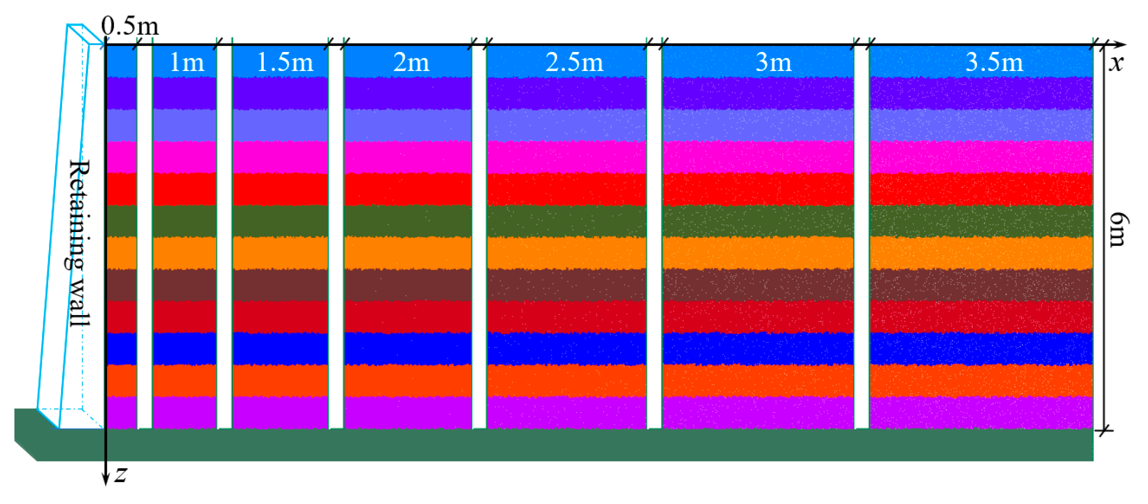
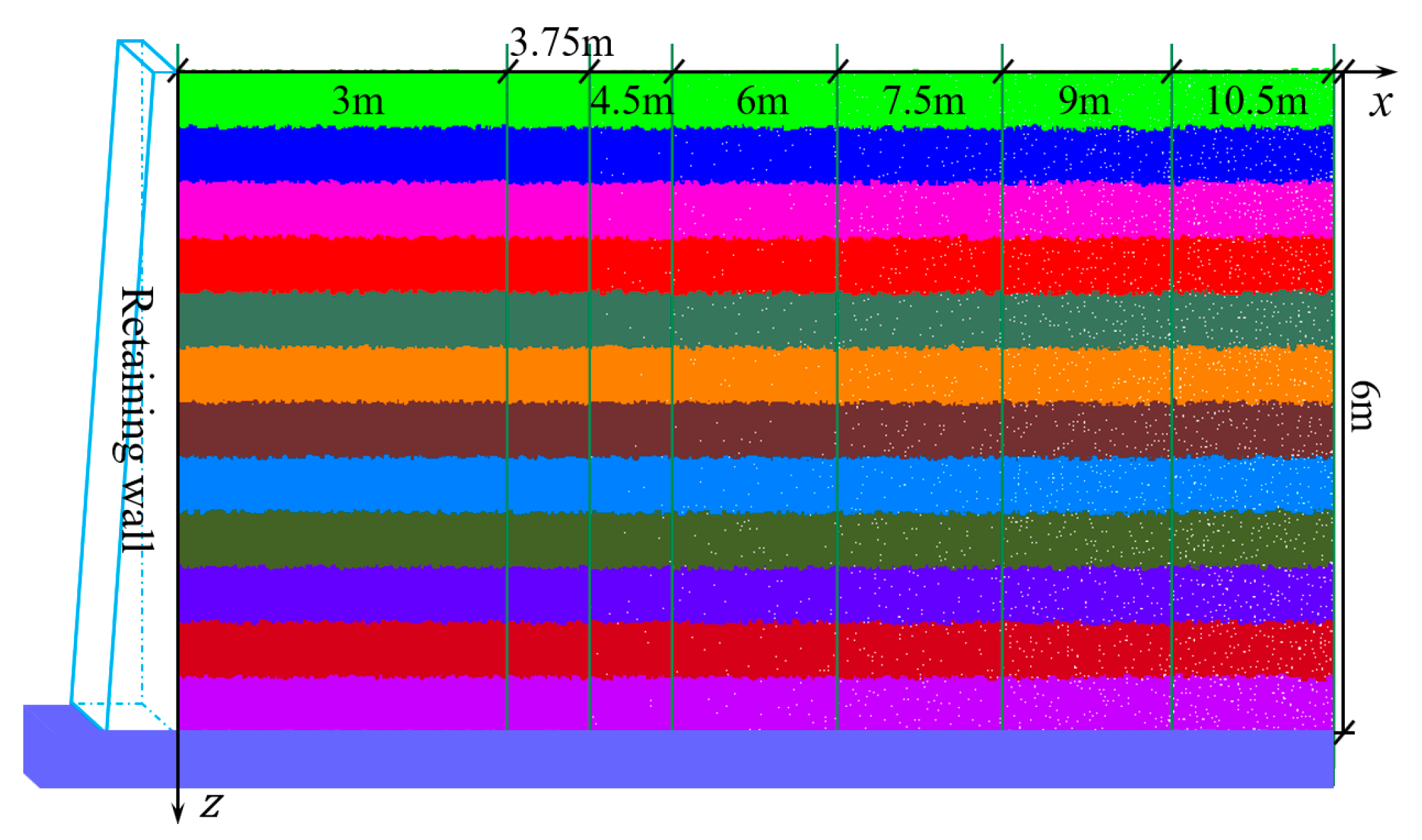
3.2. DEM Numerical Experiment

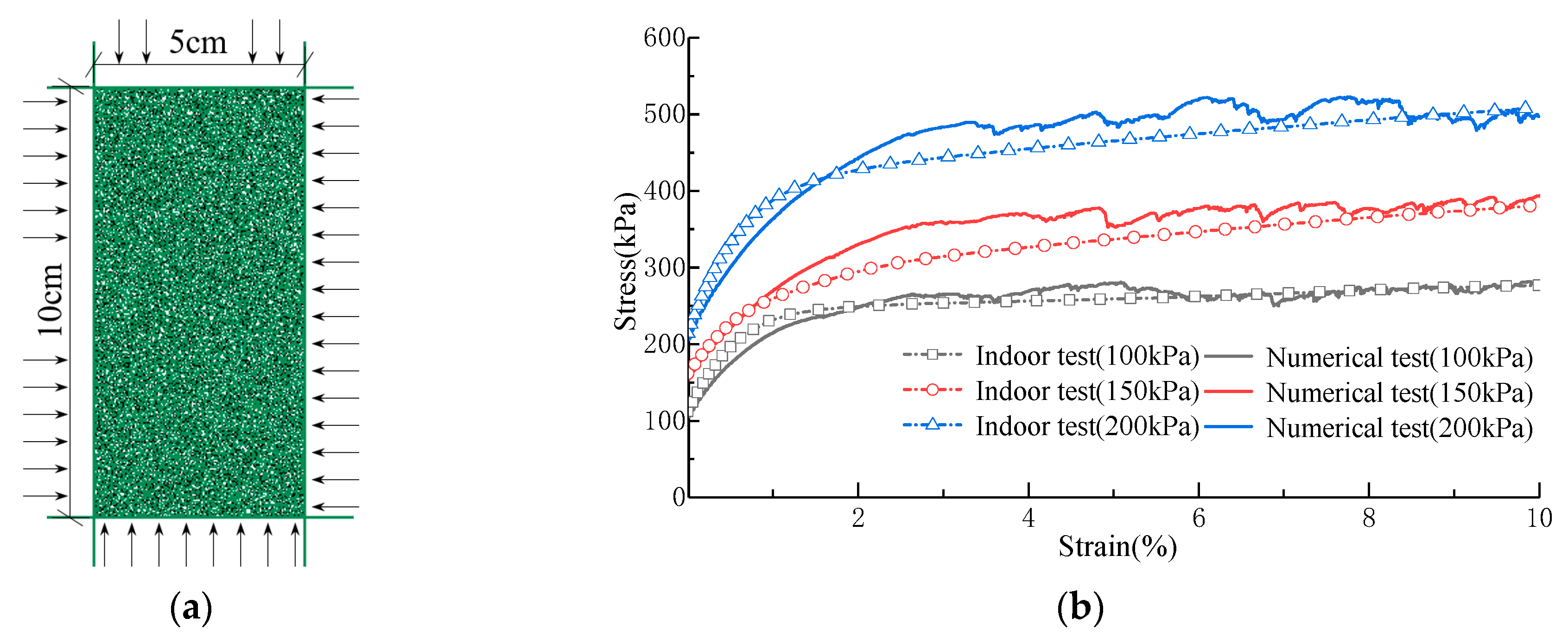
3.2.1. Parameter Selection

In this study, the discrete element software employed is PFC2D. Based on the characteristics of the stress-strain curve of the soil, it is fitted by the Adhesive Rolling Resistance Linear Model (ARRL) [44,45]. The macroscopic parameters of the tested soil samples, with the fitting target being undisturbed clay located 2 m below the ground surface of the Phase I foundation pit of the Doumen Reservoir, are detailed in Table 1.
Numerical biaxial tests are employed to calibrate the indoor triaxial test results. The test specimen dimensions are 5 cm in width and 10 cm in height. The particle sizes were selected based on the research of Ding et al. [46]. The test is conducted under confining pressures of 100 kPa, 150 kPa, and 200 kPa. The generated model is shown in Figure 6a.
After determining the approximate range of the contact model parameters, the microscopic parameters were iteratively adjusted using the dichotomy method to refine the numerical results and bring them closer to the indoor test results. The comparison between the two is illustrated in Figure 6b.
The microscopic parameters corresponding to the aforementioned stress-strain curves are listed in Table 2. The contact model between the wall and the soil was characterized by the Linear Model. The modulus of the Linear Model was specified as ten times the modulus of the soil, and the friction coefficient was defined as one-third of the parameter value of the soil contact model.

3.2.2. Active Limit Earth Pressure

To investigate the effect of the backfill width ( L ) on the active limit earth pressure, the soil height ( H ) behind the model wall is taken to be 6 m. According to Equation (10), the maximum width ( L a ) satisfying the finite soil conditions is 3.92 m. Therefore, the backfill width is varied as follows: 0.5 m, 1 m, 1.5 m, 2 m, 2.5 m, 3 m, and 3.5 m for this study. Particles are generated using the stratified rainfall method. The particle radius needs to be increased to simplify computations due to the relatively large model size compared to the particle radius. Previous studies [46,47] have demonstrated that the influence of particle size becomes negligible when the ratio of the shortest side of the model to the maximum particle radius ( R m a x ) exceeds 100. Consequently, in this study, the particle size increased by a factor of 5 to 15, depending on the backfill width behind the wall. The convergence of the calculation results is evaluated based on the ratio of the average unbalanced force to the average contact force (referred to as the ratio-average). The models generated for each width are illustrated in Figure 7.
The left wall of the model was displaced at a rate of 1 mm/s while the right wall remained stationary. The numerically calculated time steps ranged between 10−5 and 10−6 s. The earth pressure behind the wall was determined using measurement circles with a radius of 0.1 m and center spacing of 0.2 m. The measured results were then compared with the results from the Jaky formula [48], as shown in Figure 8a. The distribution of the static earth pressure under various backfill widths shows good agreement with the Jaky formula, confirming the rationality of the initial state simulation. Data were recorded at 0.5 mm intervals until the wall displacement reached 10 mm, after which recording intervals were extended to 1 mm. The active limit earth pressure in this paper was determined as the average of five data points, two preceding the minimum value and two subsequent to it. The relationship between the earth pressure resultant force and the wall displacement for each backfill width is shown in Figure 8b.
As shown in Figure 8b, as the wall displacement increases, the smaller the backfill width ( L ) behind the wall, and the faster the earth pressure on the retaining wall decreases. When L > 2 m, the rate of decrease in earth pressure diminishes rapidly. Furthermore, the wall displacement required to reach the limit state varies with backfill width, exhibiting a proportional relationship between these two parameters. The influence of backfill width on earth pressure becomes significantly reduced when the width exceeds one-third of the wall height.
To validate the method proposed in this paper, the DEM results are compared with the results of this paper, as illustrated in Figure 9a. The Pearson correlation coefficient between the two sets of results was 0.993, showing a consistent trend. The error between the two datasets decreases non-linearly as backfill width increases, ranging from a maximum of 36.2% to a minimum of 6.8%. When the backfill width behind the wall ( L ) is zero, the resultant active earth pressure force ( E a ) is also zero. As L increases, E a follows a pattern of initially increasing and then decreasing, gradually approaching the Coulomb theory considering cohesion. When L = L a (critical width), the triangular slip wedge assumed in Coulomb theory represents a special case of the trapezoidal slip wedge. The trapezoidal slip wedge assumed in this article fails prior to the triangular slip wedge. In this case, the Coulomb result is not the maximum value of the function E 1 ( θ ) due to the influence of cohesion. The depth-dependent distributions of active earth pressure under various width conditions are shown in Figure 9b. As the soil modulus exhibits a nonlinear increasing trend with burial depth, under identical soil deformation conditions, the burial depth shows proportional increases in earth pressure. The consistent variation trends between both components demonstrate the validity of the proposed methodology.
During wall displacement, pre-existing interparticle contacts may be disrupted. The formation of new contacts occurs when sufficient relative displacement develops between particles. Regions exhibiting concentrated new contacts can be considered as the location of the slip surface. The slip surface distribution and rupture angle obtained in this study under various backfill widths are shown in Figure 10.
As depicted in Figure 10, the rupture angle ( θ ) decreases with increasing backfill width ( L ) behind the wall, while the height of the slip surface inflection point progressively rises. When L / H < 1/4 and the slip wedge attain sufficient height, multiple internal failure surfaces develop within the slip wedge, resulting in a more complex distribution pattern. The lowermost slip surface shows fundamental consistency with the results of Lai et al. [32].

3.2.3. Passive Limit Earth Pressure

In the passive state, the numerical model maintains a wall height of 6 m. As determined by Equation (19), the maximum width ( L p ) of the finite soil is 11.76 m. Consequently, the backfill widths ( L ) were configured as 3 m, 3.75 m, 4.5 m, 6 m, 7.5 m, 9 m, and 10.5 m. The numerical models generated for each width are presented in Figure 11.
The static earth pressure distributions under different widths are shown in Figure 12a, which demonstrates good agreement with the Jack formula, confirming the validity of the initial simulation. The variation pattern of earth pressure resultant force with wall displacement is illustrated in Figure 12b. The passive earth pressure resultant force ( E p ) was calculated as the average of the maximum values and its four adjacent data points.
In Figure 12b, it is evident that in the passive state, the rate of increase in earth pressure behind the wall is inversely proportional to the backfill width ( L ). The resultant force of the passive limit earth pressure gradually decreases with increasing backfill width. Furthermore, the wall displacement required to reach the limit state exhibits a direct proportion to the backfill width. As L increases from 3.5 m to 10.5 m, the wall displacement needed for the soil behind the wall to reach the limit state progressively increases from 5% to 8.5% of the wall height.
The passive limit earth pressure resultant force ( E p ) under various backfill widths are shown in Figure 13a. As the backfill width ( L ) behind the wall decreases, E p demonstrates an exponential growth trend. When L / H > 1, the effect of backfill width on the earth pressure decreases sharply. At this point, the results from this study show close agreement with the Coulomb results while being marginally higher than the experimental measurements. The Pearson correlation coefficient between the two sets of results is 0.986, indicating a broadly consistent trend. The errors are positively correlated with the backfill width, ranging from a maximum of 18.4% to a minimum of 1.3%. The distribution of the earth pressure is shown in Figure 13b, and the variation trend of the results in this paper is in good agreement with the experimental results. Likewise, owing to the nonlinear increase in the soil modulus with burial depth, the increment of the earth pressure is proportional to the burial depth.
The slip surface under the passive state for various widths is depicted in Figure 14a. As the backfill width increases, the angle between the slip surface and the horizontal plane decreases linearly, and the slip surface inflection point gradually approaches the ground surface. A comparison of the earth pressure resultant forces on both sides of the slip wedge above the slip surface inflection point is shown in Figure 14b. The magnitudes of both forces are essentially identical, which validates the rationality of the assumptions proposed in this paper.

4. Parametric Analysis

The influence of various parameters on the limit earth pressure and the slip surface under different backfill widths was systematically analyzed. The initial calculation parameters are as follows: the retaining wall height ( H ) is 6 m, the unit weight ( γ ) is 17.8 kN/m3, the cohesion ( c ) is 0 kPa, the internal friction angle ( φ ) is 25°, and the wall-soil friction angle is δ = φ /3.

4.1. Effect of Various Parameters on the Active Limit State

The impact of cohesion ( c ) on the active limit earth pressure resultant force ( E a ) behind the wall is illustrated in Figure 15a. When the backfill consists of cohesionless soil, E a increases nonlinearly with growing backfill width L , but the rate of increase gradually decreases. E a reaches its maximum value at L = 4.19 m, where the corresponding width represents the critical width L a . At the critical width, both E a and θ obtained by the proposed method in this paper show complete consistency with Coulomb’s results.
For clay, the relationship between backfill width ( L ) and resultant active earth pressure force ( E a ) transitions from being initially proportional to subsequently inversely proportional. As cohesion ( c ) increases, the critical width ( L a ) progressively decreases. At L = L a , the results presented in this paper slightly exceed Coulomb’s theoretical predictions, with the discrepancy gradually increasing with higher cohesion values. This phenomenon arises because Coulomb’s triangular wedge assumption constitutes a special case of the trapezoidal wedge assumption introduced in this study. Specifically, the slip surface in Coulomb’s theory does not correspond to the maximum value of E x 1 ( θ ) . The intersection point of the E x 1 ( θ ) functions resulting from these two assumptions is the maximum value of the triangular wedge assumption (Coulomb theory), as depicted in Figure 15b.
The impact on the slip surface is shown in Figure 16. As the backfill width ( L ) increases, the rupture angle ( θ ) derived from the method presented in this study continuously decreases and gradually approaches the Coulomb rupture angle. Simultaneously, the slip surface inflection point gradually approaches the ground surface. For the same backfill width, the influence of increasing cohesion on the slip surface gradually decreases. As shown in Figure 16, cohesionless soil and clay exhibit marked differences in the variation range of rupture angles with respect to backfill width, which is attributed to the inconsistency in the values of the reaction coefficient a s .
The influence of the internal friction angle ( φ ) on the active earth pressure resultant force ( E a ) is depicted in Figure 17a. When the backfill width is constant, E a decreases inversely with increasing φ , and the effect of φ on E a gradually decreases. The leftward shift of the peak in the E a - L curve indicates an inverse proportionality between the critical width L a and φ . Since c = 0 kPa, the results in this paper at the critical width are consistent with the Coulomb earth pressure. As φ increases, the rupture angle θ exhibits a linear increase, while variations in backfill width do not alter the magnitude of the change in the rupture angle. Conversely, the rupture angle θ decreases linearly with increasing backfill width, asymptotically approaching the Coulomb rupture angle. The height at the slip surface inflection point demonstrates a nonlinear increase with higher φ . Notably, when L = L a , the rupture angle in this study coincides with the Coulomb rupture angle, and the slip surface inflection point coincides with the ground surface. Comparative analyses under varying backfill widths are depicted in Figure 17b.
The impact of the wall-soil friction angle ( δ ) on the active earth pressure resultant force ( E a ) and the slip surface is illustrated in Figure 18a,b. E a is inversely proportional to δ , and its influence diminishes rapidly as δ increases. The critical width L a increases linearly with δ . When the L = L a , the results of this paper are consistent with the Coulomb earth pressure. For aspect ratios L / H < 1/3, the rupture angle θ is directly proportional to the wall-soil friction angle δ , with a greater influence observed as the backfill width decreases. When L / H > 1/3, the rupture angle θ is inversely proportional to δ , and the larger the backfill width is, and its influence becomes more significant as the backfill width increases.

4.2. Effect of Various Parameters on the Passive Limit State

The influence of cohesion ( c ) on the passive earth pressure resultant force ( E p ) is depicted in Figure 19a. E p increases with the rise in cohesion, while the critical width ( L p ) decreases slightly as cohesion increases. When L / H > 4/3, the effect of backfill width L on E p decreases significantly. For cohesionless soil ( c = 0 kPa), the results of this study align with Coulomb theory when L = L p . For clay, the results in this study are marginally less than the Coulomb results when L = L p . This discrepancy occurs because the slip surface determined in this study is more critical than that predicted by the Coulomb theory. The Coulomb solution represents a special case in this study rather than the minimum value of the function E x 2 θ . The intersection points of the E x 2 ( θ ) functions derived from both assumptions correspond to the Coulomb solution, as shown in Figure 19b.
As the backfill width behind the wall approaches the critical width ( L p ), the discrepancy between the results obtained by the proposed method and those derived from Coulomb theory under passive state is significantly smaller than the discrepancy observed under active conditions. This discrepancy arises from the fact that the cohesion resultant force ( C ) under the passive state has a significantly smaller magnitude compared to the self-weight ( W ) and the counterforce ( R ), rendering the variation in C less influential on E p . For the specific case studied here ( c = 15 kPa, L = 11.74 m), a comparison of resultant force under passive conditions is illustrated in Figure 20a. Cohesion ( c ) also affects the distribution of the slip surface, as shown in Figure 20b. For a constant backfill width ( L ), both the rupture angle ( θ ) and the height of the slip surface inflection point ( L tan θ ) exhibit an inverse relationship with cohesion c . The effect of c on these parameters will be intensified as L increases. The rupture angle θ decreases linearly with increasing L . At the critical width, the difference between the rupture angle predicted by this study and Coulomb theory grows with increasing cohesion.
The effect of the friction angle ( φ ) on the passive earth pressure resultant force ( E p ) is shown in Figure 21a. For a constant backfill width ( L ), E p increases nonlinearly with increasing φ . The smaller the backfill width ( L ), the more pronounced the effect of φ on E p . The critical width ( L p ) is directly proportional to φ . As backfill width ( L ) decreases, E p grows exponentially. As the backfill consists of cohesionless soil, the results of this study at the critical width are consistent with Coulomb’s solution. The rupture angle (θ) decreases linearly with increasing φ , and this trend remains unaffected by variations in backfill width. A linear relationship also exists between backfill width and rupture angle. As the backfill width increases, the passive rupture angle obtained in this paper gradually decreases until it reaches the Coulomb rupture angle, as illustrated in Figure 21a.
The impact of the wall-soil friction angle ( δ ) on the passive earth pressure resultant force ( E p ) is depicted in Figure 22a. For a smooth wall back ( δ = 0), variations in backfill width behind the wall have no effect on E p . As δ increases, the relationship between E p and the backfill width transitions progressively from a horizontal line to an L-type curve. The effect of δ on E p diminishes gradually as the backfill width increases. The critical width ( L p ) increases gradually with rising wall-soil friction angle δ . At the critical width, the results obtained in this study coincide with Coulomb passive earth pressure.
The effect of the wall-soil friction angle ( δ ) on the slip surface is shown in Figure 22b. The rupture angle ( θ ) shows a linear relationship with the backfill width ( L ) behind the wall. When δ = 0, the rupture angle in this study remains constant and equals the Coulomb rupture angle. With increasing δ , θ   decreases more rapidly as L increases. For cases where the ratio of L / H is less than 9/10, θ shows directly proportional to δ , while it becomes inversely proportional to δ when L / H exceeds 9/10. At L = L p , the slip surface inflection point aligns with the ground surface, causing the trapezoidal slip wedge assumed in this study to transform into a triangular wedge.

5. Conclusions

When the backfill width behind the wall is finite, this paper posits the formation of a trapezoidal slip wedge at the limit state. According to the static equilibrium condition of the slip wedge, a calculation method for the earth pressure considering the backfill width is proposed. The effects of the cohesion, internal friction angle and wall-soil friction angle on the earth pressure were systematically investigated. The principal findings can be summarized as follows:
(1)
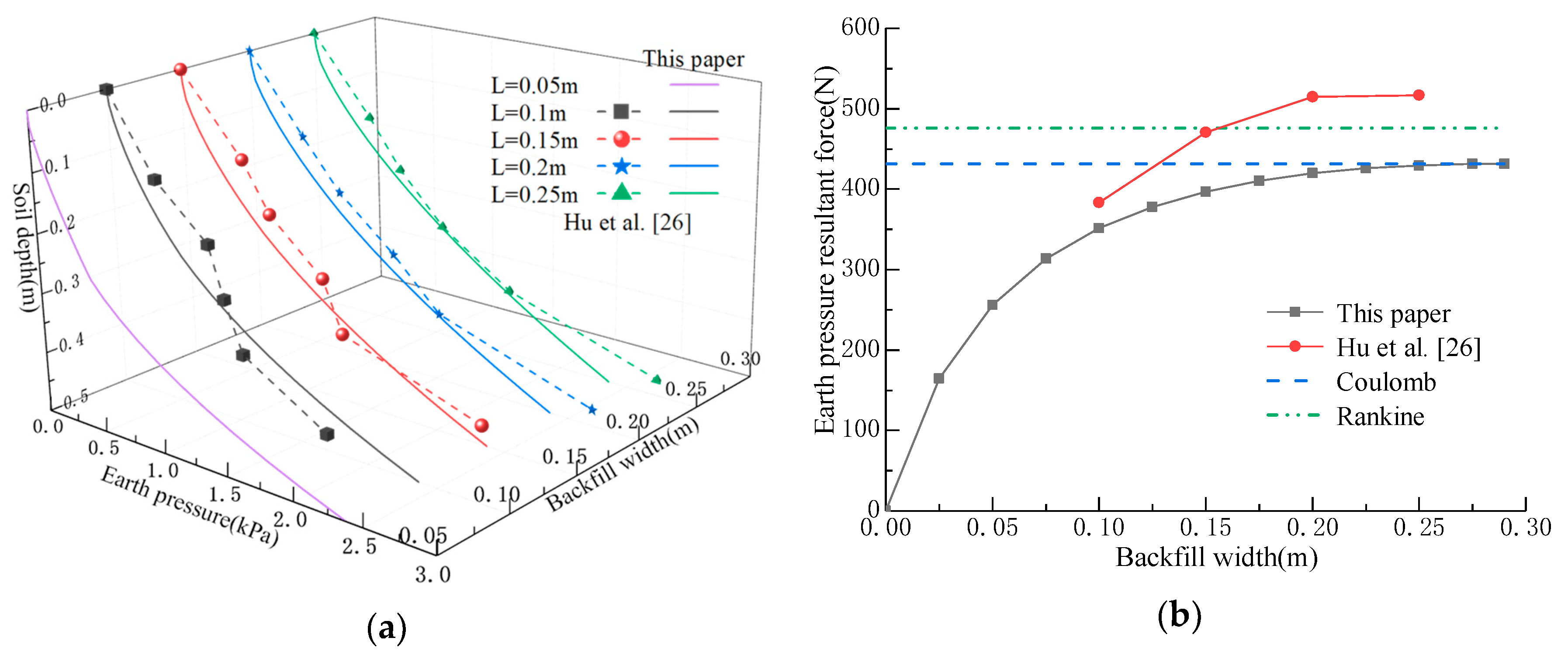
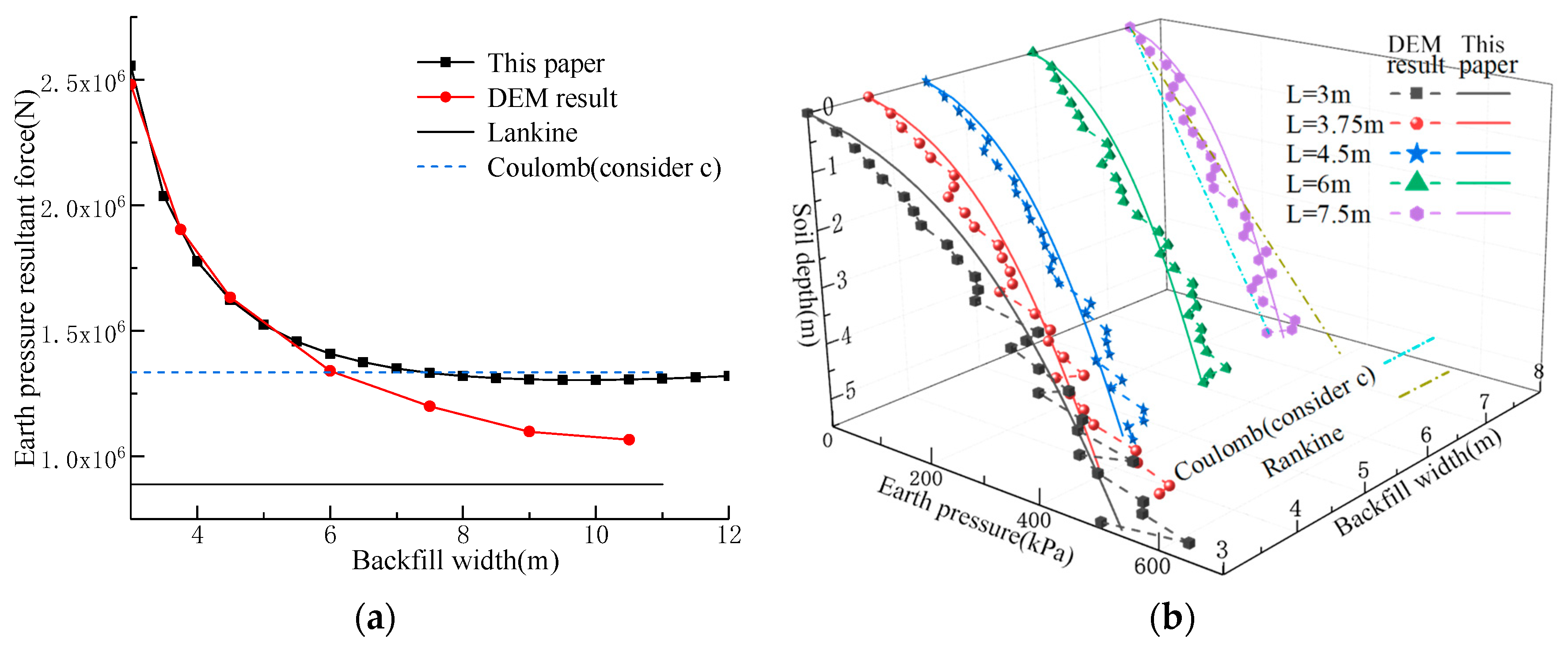
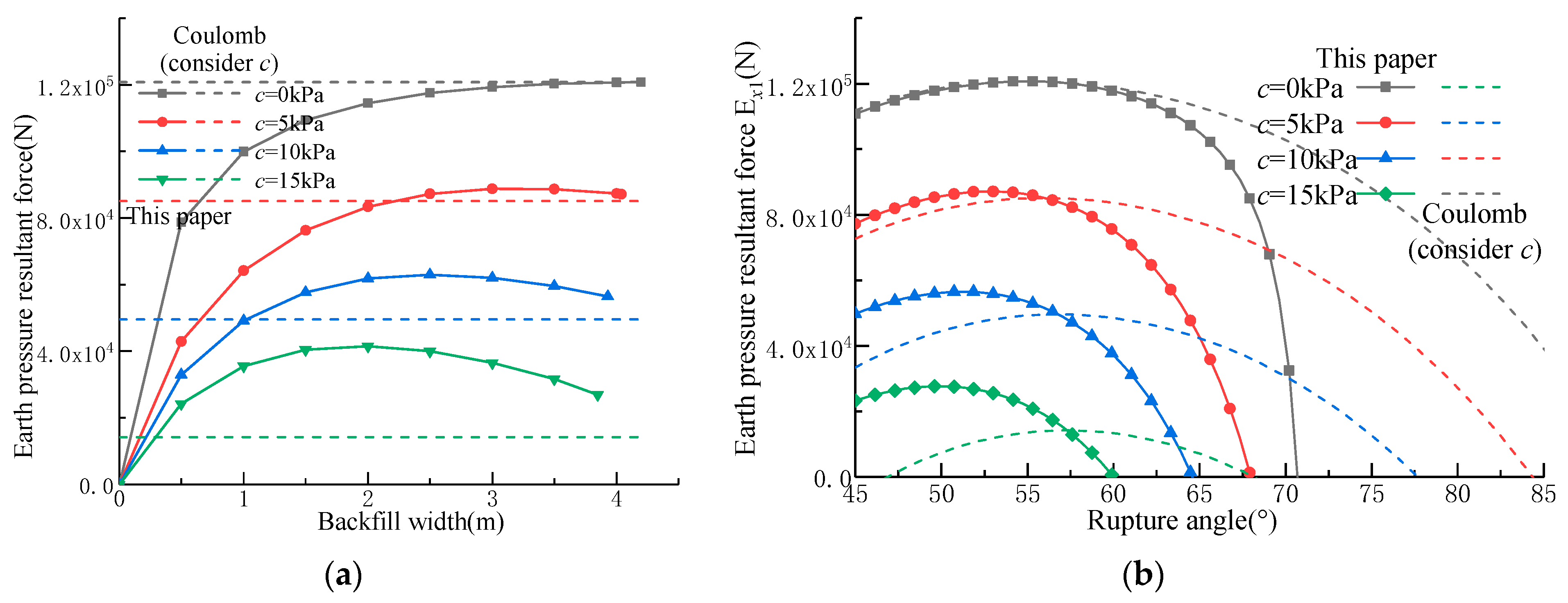
Under the active limit state, the earth pressure resultant force behind the wall exhibits a parabolic relationship with the backfill width. For cohesionless soil, the earth pressure continuously increases until it reaches the Coulomb active earth pressure, while clay experiences an initial increase followed by a decrease in earth pressure.
(2)
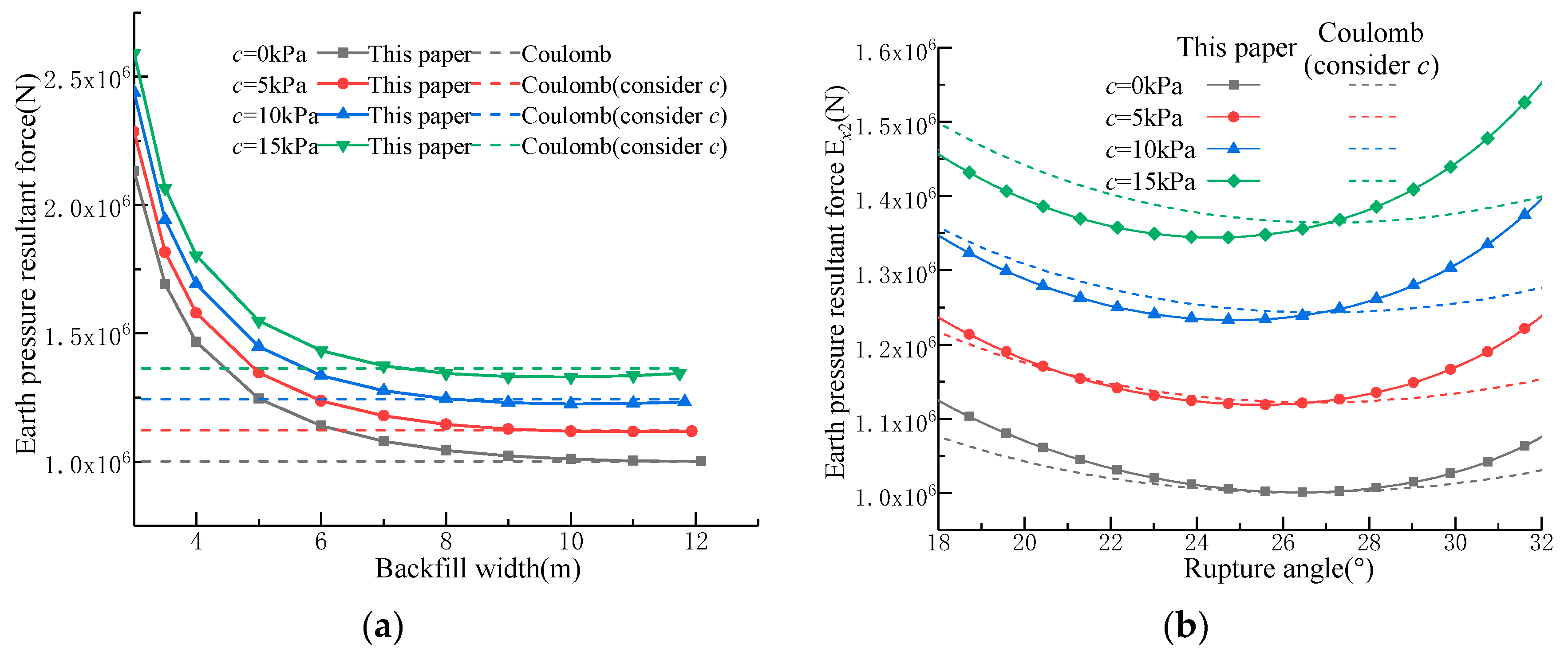
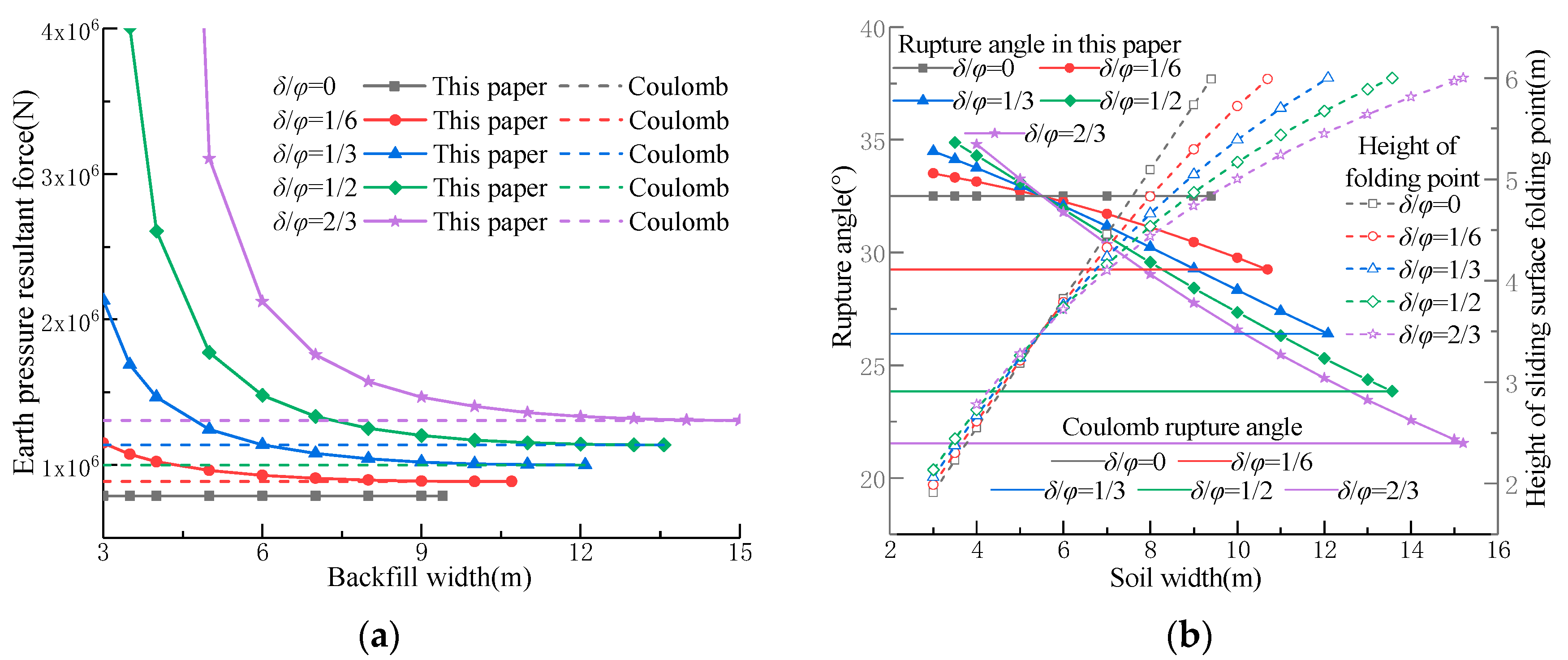
For cohesionless soils with a smooth wall back, the passive earth pressure resultant force obtained by the proposed method fully coincides with the Coulomb’s solution within the critical width range, and the corresponding rupture angles equal to the Coulomb value. As the wall-soil friction angle increases, the influence of backfill width on the passive earth pressure becomes increasingly pronounced, while exhibiting distinct exponential decay characteristics with increasing backfill dimensions.
(3)
Upon reaching the critical width, the approach presented in this paper can be simplified to the Coulomb theory for cohesionless soil. For clay, the results obtained in this paper are higher than those predicted by the Coulomb theory under an active state while being slightly lower under a passive state.
(4)
For a given backfill width, the cohesion c is inversely proportional to the resultant active limit earth pressure force E a and directly proportional to the resultant passive limit earth pressure force E p . As the internal friction angle φ increases, E a decreases nonlinearly, while E p experiences a significant growth. Furthermore, variations in the wall-soil friction angle δ have a relatively minor influence on E a , whereas E p grows exponentially with increasing δ .

Author Contributions

Conceptualization, X.W. and F.D.; writing—original draft preparation, X.W. and F.D.; validation, X.W., L.Z. and J.G.; formal analysis, X.C. and H.X.; funding acquisition F.D., J.G. and H.X. All authors have read and agreed to the published version of the manuscript.

Funding

This research was supported by the National Natural Science Foundation of China (No. 51979225, 52009107, 52309172), the Key Laboratory for Science and Technology Coordination and Innovation Projects of Shaanxi Province (No. 2014SZS15-Z01) and the Natural Science Foundation of Shaanxi Province (No. 2020JQ-584).

Institutional Review Board Statement

Not applicable.

Informed Consent Statement

Not applicable.

Data Availability Statement

The data used to support the findings of this study are available from the corresponding author upon reasonable request.

Conflicts of Interest

The authors declare no conflict of interest.

Abbreviations

E x The resultant earth pressure on the retaining wall
R Reaction forces on the slip wedge by the soil below the slip surface
W The weight of the slip wedge
S The reaction force exerted on the slip wedge by the soil below the slip surface
C The resultant cohesive force on the slip surface
H The height of the retaining wall
L The width of backfill behind the wall
a S The reaction coefficient
θ The rupture angle
δ The wall-soil friction angle
c The cohesive force
φ The internal friction angle
γ The unit weight of soil
ψ Intermediate variable (Tangent value of rupture angle θ )
A n ~ G n Intermediate variable, n = 1~4. (Related to γ , c , φ , δ , H , L , a s )
a n ~ e n Intermediate variable, n = 1~2. (Related to A n ~ G n )
λ n , η n Intermediate variable, n = 1~2. (Related to a n ~ e n )
Δ n The solution of the quartic equation of one variable, n = 1~2. (Related to a n , λ n , η n )
E t The tangent modulus in the Duncan model
R f The failure ratio
K The modulus parameter
P a The atmospheric pressure
n The dimensionless index
μ The Poisson’s ratio
σ x The stress in x direction
σ 3 The minor principal stress
ε x The strain in x direction
ε x m a x The limit strain in x direction
K 0 The coefficient of earth pressure at rest

References

  1. Lee, S.G.; Hencher, S.R. The repeated failure of a cut-slope despite continuous reassessment and remedial works. Eng. Geol. 2009, 107, 16–41. [Google Scholar] [CrossRef]
  2. Chen, F.Q.; Yang, J.T.; Lin, Y.J. Active earth pressure of narrow granular backfill against rigid retaining wall near rock face under translation mode. Int. J. Geomech. 2019, 19, 04019133. [Google Scholar] [CrossRef]
  3. Xie, M.X.; Zheng, J.J.; Zhang, R.J.; Cui, L.; Miao, C. Active earth pressure on rigid retaining walls built near rock faces. Int. J. Geomech. 2020, 20, 04020061. [Google Scholar] [CrossRef]
  4. Xu, L.; Chen, H.B.; Chen, F.Q.; Lin, Y.J.; Lin, C. An experimental study of the active failure mechanism of narrow backfills installed behind rigid retaining walls conducted using Geo-PIV. Acta Geotech. 2020, 17, 4051–4068. [Google Scholar] [CrossRef]
  5. Frydman, S.; Keissar, I. Earth pressure on retaining walls near rock faces. Int. J. Geotech. Eng. 1987, 113, 586–599. [Google Scholar] [CrossRef]
  6. Take, W.A.; Valsangkar, A.J. Earth pressures on unyielding retaining walls of narrow backfill width. Can. Geotech. J. 2001, 38, 1220–1230. [Google Scholar] [CrossRef]
  7. Paik, K.H.; Salgado, R. Estimation of active earth pressure against rigid retaining walls considering arching effects. Geotechnique 2003, 53, 643–653. [Google Scholar] [CrossRef]
  8. Yang, B.; Shi, Q.Y.; Zhou, H.X.; Qin, C.; Xiao, W.W. Study on distribution of sidewall earth pressure on open caissons considering soil arching effect. Sci. Rep. 2023, 13, 10657. [Google Scholar] [CrossRef] [PubMed]
  9. Yang, M.H.; Tang, X.C. Rigid retaining walls with narrow cohesionless backfills under various wall movement modes. Int. J. Geomech. 2017, 17, 04017098. [Google Scholar] [CrossRef]
  10. Yang, M.H.; Tang, X.C.; Wu, Z.Y. Slip surface and active earth pressure of cohesionless narrow backfill behind rigid retaining walls under translation movement mode. Int. J. Geomech. 2020, 20, 04020115. [Google Scholar] [CrossRef]
  11. Hu, H.B.; Yang, F.; Tang, H.B.; Zeng, Y.J.; Zhou, J.J.; Gong, X.N. Field Study on Earth Pressure of Finite Soil Considering Soil Displacement. Appl. Sci. 2022, 12, 8059. [Google Scholar] [CrossRef]
  12. Fan, C.C.; Fang, Y.S. Numerical solution of active earth pressures on rigid retaining walls built near rock faces. Comput. Geotech. 2010, 37, 1023–1029. [Google Scholar] [CrossRef]
  13. Yang, M.H.; Deng, B. Simplified method for calculating the active earth pressure on retaining walls of narrow backfill width based on DEM analysis. Adv. Civ. Eng. 2019, 2019, 1507825. [Google Scholar] [CrossRef]
  14. Li, M.G.; Chen, H.B.; Chen, J.J.; Lin, T. Discrete element analysis and analytical method on failure mechanism of retaining structures with narrow granular backfill. Int. J. Numer. Anal. Met. 2024, 48, 629–652. [Google Scholar] [CrossRef]
  15. Chen, F.Q.; Lin, Y.J.; Yang, J.T. Passive earth pressure of narrow cohesionless backfill against inclined rigid retaining walls under translation mode. Soils Found. 2020, 60, 1226–1240. [Google Scholar] [CrossRef]
  16. Chen, F.Q.; Lin, Y.J.; Yang, J.T.; Huang, M. Passive Earth pressure of narrow cohesionless backfill against rigid retaining walls rotating about the base. Int. J. Geomech. 2021, 21, 06020036. [Google Scholar] [CrossRef]
  17. Yang, D.Y.; Lai, F.W.; Liu, S.Y. Earth pressure in narrow cohesive-fictional soils behind retaining walls rotated about the top: An analytical approach. Comput. Geotech. 2022, 149, 104849. [Google Scholar] [CrossRef]
  18. Wang, Y.; Chen, H.B.; Jiang, G.P.; Chen, F.Q. Slip-Line Solution for the Active Earth Pressure of Narrow and Layered Backfills against Inverted T-Type Retaining Walls Rotating about the Base. Int. J. Geomech. 2023, 23, 04023044. [Google Scholar] [CrossRef]
  19. Chen, F.Q.; Chen, C.; Kang, W.Z.; Li, X.B. Slip-line solution to seismic active earth pressure of narrow c-φ soils on gravity walls rotating about the bottom. Soil. Dyn. Earthq. Eng. 2024, 181, 108625. [Google Scholar] [CrossRef]
  20. Tang, Y.; Chen, J. A computational method of active earth pressure from finite soil body. Math. Probl. Eng. 2018, 2018, 9892376. [Google Scholar] [CrossRef]
  21. Chen, F.; Lin, Y.; Li, D. Solution to active earth pressure of narrow cohesionless backfill against rigid retaining walls under translation mode. Soils Found. 2019, 59, 151–161. [Google Scholar] [CrossRef]
  22. Lin, Y.J.; Chen, F.Q.; Yang, J.T.; Li, D.Y. Active earth pressure of narrow cohesionless backfill on inclined rigid retaining walls rotating about the bottom. Int. J. Geomech. 2020, 20, 04020102. [Google Scholar] [CrossRef]
  23. Khosravi, M.H.; Sarfaraz, H.; Pipatpongsa, T.; Sharifdeljuyi, A. Active Earth Pressure Distribution inside Narrow Backfill Considering Soil-Arching Effect. Int. J. Geomech. 2022, 22, 06022013. [Google Scholar] [CrossRef]
  24. Chen, H.B.; Chen, F.Q.; Lin, Y.J. Slip-line solution to earth pressure of narrow backfill against retaining walls on yielding foundations. Int. J. Geomech. 2022, 22, 04022051. [Google Scholar] [CrossRef]
  25. Wang, W.W.; Liu, X.X.; Li, B.; Luo, H. Passive Earth Pressure on the Retaining Wall of Limited-width Backfill Based on Curvilinearly Layered. Ksce J. Civ. Eng. 2020, 26, 4489–4499. [Google Scholar] [CrossRef]
  26. Hu, W.; Zhu, X.; Zeng, Y.Q.; Liu, X.H.; Peng, C.C. Active earth pressure against flexible retaining wall for finite soils under the drum deformation mode. Sci. Rep. 2022, 12, 497. [Google Scholar] [CrossRef] [PubMed]
  27. Li, C.T.; Lai, F.W.; Shiau, J.; Keawsawasvong, S.; Huang, H.H. Passive Earth Pressure in Narrow Cohesive-Frictional Backfills. Int. J. Geomech. 2023, 23, 04022262. [Google Scholar] [CrossRef]
  28. Wang, Z.Y.; Liu, X.X.; Wang, W.W.; Tao, Z.Y.; Li, S. Inclined layer method-based theoretical calculation of active earth pressure of a finite-width soil for a rotating-base retaining wall. Sustainability 2022, 14, 9772. [Google Scholar] [CrossRef]
  29. Fu, D.X.; Yang, M.H.; Deng, B.; Gong, H.T. Estimation of active earth pressure for narrow unsaturated backfills considering soil arching effect and interlayer shear stress. Sustainability 2022, 14, 12699. [Google Scholar] [CrossRef]
  30. Liu, H.; Kong, D.Z. Active earth pressure of finite width soil considering intermediate principal stress and soil arching effects. Int. J. Geomech. 2022, 22, 04021294. [Google Scholar] [CrossRef]
  31. Liu, H.; Kong, D.Z. Nonlinear description of active earth pressure for finite backfill based on principal stress trajectory method subjected to steady unsaturated seepage. Comput. Geotech. 2022, 158, 105357. [Google Scholar] [CrossRef]
  32. Lai, F.W.; Yang, D.Y.; Liu, S.Y.; Zhang, H.; Cheng, Y. Towards an improved analytical framework to estimate active earth pressure in narrow c–ϕ soils behind rotating walls about the base. Comput. Geotech. 2022, 141, 104544. [Google Scholar] [CrossRef]
  33. Huang, K.; Liu, R.N.; Sun, Y.W.; Li, L.Y.; Xie, Y.P.; Peng, X.J. Study on the calculation method of active earth pressure and critical width for finite soil behind the retaining wall. Front. Earth Sci. 2022, 10, 883668. [Google Scholar] [CrossRef]
  34. Li, M.G.; Chen, H.B.; Chen, J.J.; Lin, T. Semianalytical Solution for Earth Pressure of Narrow Granular Backfill with a Log-Spiral Failure Surface behind Retaining Walls under Translational Mode. Int. J. Geomech. 2023, 23, 04023151. [Google Scholar] [CrossRef]
  35. Baker, R.; Klein, Y. An integrated limiting equilibrium approach for design of reinforced soil retaining structures: Part II—Design examples. Geotext Geomembr. 2004, 22, 151–177. [Google Scholar] [CrossRef]
  36. Mohamed, S.B.A.; Yang, K.H.; Hung, W.Y. Finite element analyses of two-tier geosynthetic-reinforced soil walls: Comparison involving centrifuge tests and limit equilibrium results. Comput. Geotech. 2014, 61, 67–84. [Google Scholar] [CrossRef]
  37. Su, L.J.; Yin, J.H.; Zhou, W.H. Influences of overburden pressure and soil dilation on soil nail pull-out resistance. Comput. Geotech. 2010, 37, 555–564. [Google Scholar] [CrossRef]
  38. Hu, W.D.; Zhu, X.N.; Liu, X.H.; Zeng, Y.Q.; Zhou, X.Y. Active earth pressure against cantilever retaining wall adjacent to existing basement exterior wall. Int. J. Geomech. 2020, 20, 04020207. [Google Scholar]
  39. Rui, R.; Ye, Y.Q.; Han, J.; Zhang, L.; Zhai, Y.X. Experimental and theoretical investigations on active earth pressure distributions behind rigid retaining walls with narrow backfill under a translational mode. Int. J. Geomech. 2020, 20, 04020178. [Google Scholar] [CrossRef]
  40. Chen, H.B.; Chen, F.Q.; Chen, C.; Lai, D.L. Failure Mechanism and Active Earth Pressure of Narrow Backfills behind Retaining Structures Rotating about the Base. Int. J. Geomech. 2024, 24, 04024068. [Google Scholar] [CrossRef]
  41. Zhang, L.; Dang, F.N.; Wang, X.; Ding, J.L.; Gao, J.; Zhang, Y. Estimation of earth pressure against retaining walls with different limited displacement modes based on elastic theory. J. Mt. Sci. 2022, 19, 289–304. [Google Scholar] [CrossRef]
  42. Ying, H.W.; Zhang, J.H.; Wang, X.G.; Li, B.H.; Zhu, W. Experimental analysis of passive earth pressure against rigid retaining wall under translation mode for finite soils. Chin. J. Geotech. Eng. 2016, 38, 978–986. (In Chinese) [Google Scholar]
  43. Pain, A.; Chen, Q.S.; Nimbalkar, S.; Zhou, Y.T. Evaluation of seismic passive earth pressure of inclined rigid retaining wall considering soil arching effect. Soil Dyn. Earthq. Eng. 2017, 100, 286–295. [Google Scholar] [CrossRef]
  44. Gilabert, F.A.; Roux, J.N.; Castellanos, A. Computer simulation of model cohesive powders: Plastic consolidation, structural changes, and elasticity under isotropic loads. Phys. Rev. E 2008, 78, 031305. [Google Scholar] [CrossRef] [PubMed]
  45. Bao, X.; Bao, Z.; Shen, J.; Chen, X.; Wu, X.; Cui, H. Dynamic properties of sand with different contents of clay. Powder Technol. 2024, 431, 119070. [Google Scholar] [CrossRef]
  46. Ding, X.; Zhang, L.; Zhu, H.; Zhang, Q. Effect of model scale and particle size distribution on PFC3D simulation results. Rock Mech. Rock Eng. 2014, 47, 2139–2156. [Google Scholar] [CrossRef]
  47. Yang, B.D.; Jiao, Y.; Lei, S. A study on the effects of microparameters on macroproperties for specimens created by bonded particles. Eng. Comput. 2006, 23, 607–631. [Google Scholar] [CrossRef]
  48. Jaky, J. The coefficient of earth pressure at rest. J. Soc. Hung. Archit. Eng. 1944, 355–358. [Google Scholar]
Figure 1. Force analysis of the slip wedge in the active state: (a) cohesionless soil; (b) clay.
Applsci 15 01750 g001
Figure 2. Force analysis of the clay slip wedge in the passive state.
Applsci 15 01750 g002
Figure 3. Force analysis of cohesionless soils in the passive limit state.
Applsci 15 01750 g003
Figure 4. (a) Distribution of active earth pressure; (b) Comparison of earth pressure resultant force.
Applsci 15 01750 g004
Figure 5. (a) Distribution of passive earth pressure; (b) Comparison of earth pressure resultant force.
Applsci 15 01750 g005
Figure 6. (a) Biaxial test model; (b) Comparison of stress-strain curves.
Applsci 15 01750 g006
Figure 7. Numerical model under the active state.
Applsci 15 01750 g007
Figure 8. (a) Static earth pressure with different backfill widths; (b) Relationship between the active earth pressure resultant force and displacement.
Applsci 15 01750 g008
Figure 9. (a) Relationship between the width of the soil behind the wall and E a ; (b) Distribution of earth pressure at various widths.
Applsci 15 01750 g009
Figure 10. Distribution of new contacts under different backfill widths.
Applsci 15 01750 g010
Figure 11. Numerical model under the passive state.
Applsci 15 01750 g011
Figure 12. (a) Static earth pressure with different backfill widths; (b) Relationship between the passive earth pressure resultant force and displacement.
Applsci 15 01750 g012
Figure 13. (a) Relationship between the width of the soil behind the wall and E p ; (b) Distribution of earth pressure at various widths.
Applsci 15 01750 g013
Figure 14. (a) Distribution of new contacts under different backfill widths; (b) Comparison of resultant forces on both sides above the inflection point.
Applsci 15 01750 g014
Figure 15. (a) Effect of cohesion c on E a ; (b) Comparison of E x 1 ( θ ) formed by triangular and trapezoidal wedges.
Applsci 15 01750 g015
Figure 16. Effect of cohesion c on the slip surface.
Applsci 15 01750 g016
Figure 17. (a) Effect of cohesion φ on E a ; (b) Effect of the friction angle φ on the slip surface.
Applsci 15 01750 g017
Figure 18. (a) Effect of wall-soil friction angle δ on E a ; (b) Effect of wall-soil friction angle δ on the slip surface.
Applsci 15 01750 g018
Figure 19. (a) Effect of cohesion c on E p ; (b) Comparison of E x 1 ( θ ) formed by triangular and trapezoidal wedges.
Applsci 15 01750 g019
Figure 20. (a) Relationship between the resultant forces and the failure angle; (b) Effect of cohesion c on the slip surface.
Applsci 15 01750 g020
Figure 21. (a) Effect of the friction angle φ on E p ; (b) Effect of the friction angle φ on the slip surface.
Applsci 15 01750 g021
Figure 22. (a) Effect of the wall-soil friction angle δ on E p ; (b) Effect of wall-soil friction angle δ on the slip surface.
Applsci 15 01750 g022
Table 1. Physical and mechanical parameters of the soil samples.
Proportion   G s (g/cm3)Density (g/cm3)Void Ratio c /kPa φ
2.71.780.8081424.6
Table 2. Microscopic parameters.
Particle Density (kg/m3)Grain Size (mm) Effective   Modulus   E * (MPa) Stiffness   Ratio   k * Friction   Coefficient   μ Rolling   Friction   Coefficient   μ r Maximum Attractive Force (N)Attraction Range (mm)
26500.71~0.18353.60.210.8100.35
Disclaimer/Publisher’s Note: The statements, opinions and data contained in all publications are solely those of the individual author(s) and contributor(s) and not of MDPI and/or the editor(s). MDPI and/or the editor(s) disclaim responsibility for any injury to people or property resulting from any ideas, methods, instructions or products referred to in the content.

