1. Introduction
Since the 1800s, auscultation has been a vital component of clinical examination. It is a cost-effective method for detecting abnormal signs [
1] and continues to be a crucial tool in the 2020s, given that cardiopulmonary disease is a leading cause of death and illness, significantly impacting quality of life and healthcare costs [
2]. The ability of electronic stethoscopes to treat auscultatory sounds as quantitative data has led to much research on automated diagnosis with AI [
3,
4]. Regarding heart sounds, AI models have been developed to analyze heart sounds for the detection of valvular heart diseases (VHDs) [
5]. AI has also been applied to the analysis of lung sounds. Research indicates that AI can detect pathological breath sounds, such as crackles and wheezes, with a reasonably high degree of accuracy from recordings obtained via digital stethoscopes [
6]. These advancements suggest that AI has significant potential to enhance the detection of abnormal heart and lung sounds, thereby improving diagnostic processes in healthcare.
Despite these technological advances, during auscultation, patients are required to fully expose their chests so doctors can place the stethoscope directly on the skin for accurate diagnostic results. However, in many cultures, patients may feel uncomfortable with a doctor of the opposite gender performing auscultation, especially in areas requiring partial undressing. Patients may also hesitate to voice their discomfort, potentially leading to stress or dissatisfaction with the examination. To preserve modesty, some patients might refuse to undress, leading to auscultation over clothing, which diminishes sound quality and diagnostic accuracy [
7]. As psychological factors, gender mismatches may increase patient anxiety, leading to physiological changes (e.g., rapid heartbeat), which could interfere with the examination results [
8]. Regardless of gender, removing clothing is time-consuming, particularly when multiple layers are involved, and patients often feel cold during the examination. Therefore, there is a critical demand for technology that can assist in auscultation and eliminate the gender difference between the doctor and the patient.
We believe that robot technology can address these issues. In terms of enhancing the comfort of patients, robots lack gender identity, which can reduce discomfort or anxiety for patients who might feel uneasy with a doctor of a different gender. Robots can also be programmed to prioritize patient privacy, further alleviating concerns about sensitive physical examinations. In terms of objectivity and accuracy, robots can be programmed to perform tasks consistently and objectively, reducing potential bias or hesitation due to gender differences, and they can ensure a thorough and methodical approach to auscultation that is unaffected by any discomfort or psychological hesitation a human doctor might experience. Thus, robot-assisted auscultation systems enable exams to be conducted remotely, eliminating the need for physical contact between doctors and patients and avoiding direct contact with the patient’s body. When integrated with AI, they can analyze auscultation sounds independently, reducing the need for human intervention during the examination.
1.1. Related Works
Robot-assisted diagnosis has mainly focused on ultrasonography for the past two decades, with research categorized as teleoperated, semiautomated, and fully automated [
9,
10]. Robot-assisted ultrasonography has been extensively studied and applied to a variety of medical targets such as cardiovascular system [
11,
12], obstetrics and gynecology [
13,
14,
15,
16], abdominal imaging [
17,
18,
19,
20], vascular system [
21], emergency care [
22], and COVID-19 [
23,
24]. Ultrasonography and auscultation share several similarities when it comes to the integration of robot assistance, as both involve the acquisition and interpretation of physiological signals and rely on precise tool handling for optimal results. Both fields benefit from improved precision, automation, and AI integration, paving the way for more efficient, standardized, and patient-friendly healthcare practices. Meanwhile, there are few studies on robot assistance focused on auscultation so far.
Several studies have focused on developing robot-assisted auscultation systems. Falleni et al. potentially introduced the first such system, emphasizing remote auscultation with a design incorporating a three-Degrees-of-Freedom (DoFs) robotic arm and an RGB-D camera [
25]. This system operates at two sites: the patient site, where a robot holds a stethoscope and streams video via an RGB-D sensor, and the doctor site, where a haptic interface allows the physician to control the stethoscope and receive real-time audio and visual feedback. Zhu et al. reported on the development and implementation of an autonomous robotic system for auscultation [
26]. This system uses Bayesian Optimization (BO) and machine learning models to capture high-quality heart and lung sounds by leveraging visual anatomical cues and auditory feedback. Experiments with human subjects demonstrated that the robot achieved sound quality comparable to that of human tele-operation. This technology holds promise for reducing healthcare risks, promoting preventive care, and providing diagnostic utility, including the unexpected detection of cardiac pathology. Lopes et al. proposed a robotic system for autonomous auscultation equipped with a UR3e robotic arm and an RGB-D camera to identify and reach auscultation points on a patient’s body [
27]. This system was tested on six patients with varying physical characteristics, demonstrating its versatility and effectiveness. Our team has also developed a robot-assisted auscultation system comprising a 6 DoFs cooperative robotic arm, an RGB-D camera, and a constant-force passive-actuated mechanism that maintains the contact force of the stethoscope passively [
28,
29]. To move toward fully automated auscultation, we estimated the listening positions based on the features of the body surface. Additionally, we experimentally investigated the effect of acoustic attenuation caused by clothing. Our findings indicate that the collected sound is attenuated by the thickness of the clothing, and compressing the clothing with a stethoscope suppresses this sound attenuation.
All the aforementioned robotic systems use robotic arms to place the stethoscope. Even when cooperative robotic arms are employed, the movement velocity must be regulated for patient safety. This regulation makes the examination process less efficient and more time-consuming than traditional human procedures. Therefore, there is a demand for a robotic system that can provide safe and efficient auscultation.
1.2. Contributions
The major limitation of previous studies is that the examination process is less efficient and more time-consuming than traditional human procedures due to the regulation of the velocity of the robot arm to ensure the patient’s safety. To address this limitation, this study aimed to develop a novel robotic auscultation system capable of safely acquiring chest and back auscultatory sounds simultaneously without actuators. The proposed robotic system is equipped with a multi-acoustic sensor array that adapts to the patient’s body shape, allowing each sensor to be positioned accurately at the chest and back auscultation points. In order to adapt to the body shape, this study developed a unique actuator-less hugging mechanism that can be transformed to wrap around the chest and back to fit the patient’s body shape using only the patient’s pushing force, thanks to an articulated arm with multi-layer gear coupling and a cam mechanism for patient power transmission. To the best of our knowledge, this is the first mechanism designed to capture chest and back auscultatory sounds concurrently corresponding to the patient’s body shape without any actuators. The superiority of this actuator-less mechanism is that (1) the patient is not harmed by a sensor failure or uncertain control of the actuator and (2) efficient and personalized auscultation can be performed.
Section 2 introduces the final concept of our robot-assisted auscultation system and the detailed design and implementation of the proposed hugging mechanism.
Section 3 represents the experimental results of the performance of the hugging mechanism corresponding to various body shapes, and
Section 4 discusses the experimental results and future research directions.
2. Materials and Methods
2.1. Conceptual Design
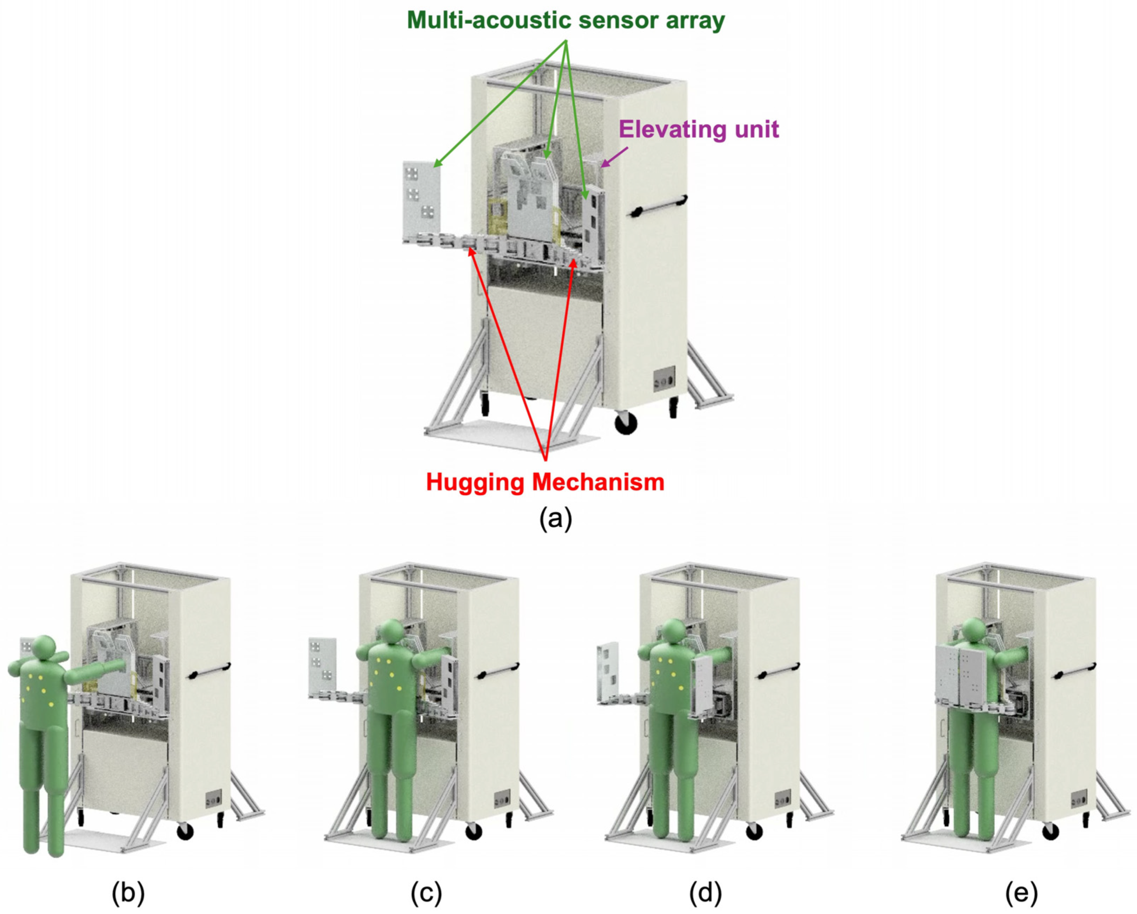
Figure 1 shows a conceptual illustration of the proposed robot-assisted auscultation system. The system comprises a multi-acoustic sensor array, a hugging mechanism, and an elevating unit. The multi-acoustic sensor array has a number of acoustic sensors. The arrangement of the acoustic sensors is based on the listening position of cardiac and respiratory sounds corresponding to individual differences in body shape. The hugging mechanism has an actuator-less articulated twin arm, whose role is to transform the multi-acoustic sensor array so that it wraps around the patient’s chest and back according to the size of the body shape. The corresponding body shapes are broadly classified into three categories: slender, standard, and obese. Additionally, this hugging mechanism can be transformed by pushing with the weight of the examinee without the use of any actuators. The elevating unit elevates the hugging mechanism equipped with the muti-acoustic sensor array according to the patient’s height.
The operational flow using this device is as follows. First, a patient stands in front of this system, and the elevating unit then adjusts the position of the hugging mechanism fitting to the height of patient. Next, the patient pushes the device under its own weight. Then, the hugging mechanism operates and wraps around the patient’s chest and back. At this time, the trajectory of the hugging mechanism is controlled from the patient’s body shape. After that, the multi-acoustic sensor array equipped with the hugging mechanism starts recording the cardiac and breathing sounds.
2.2. Hugging Mechanism
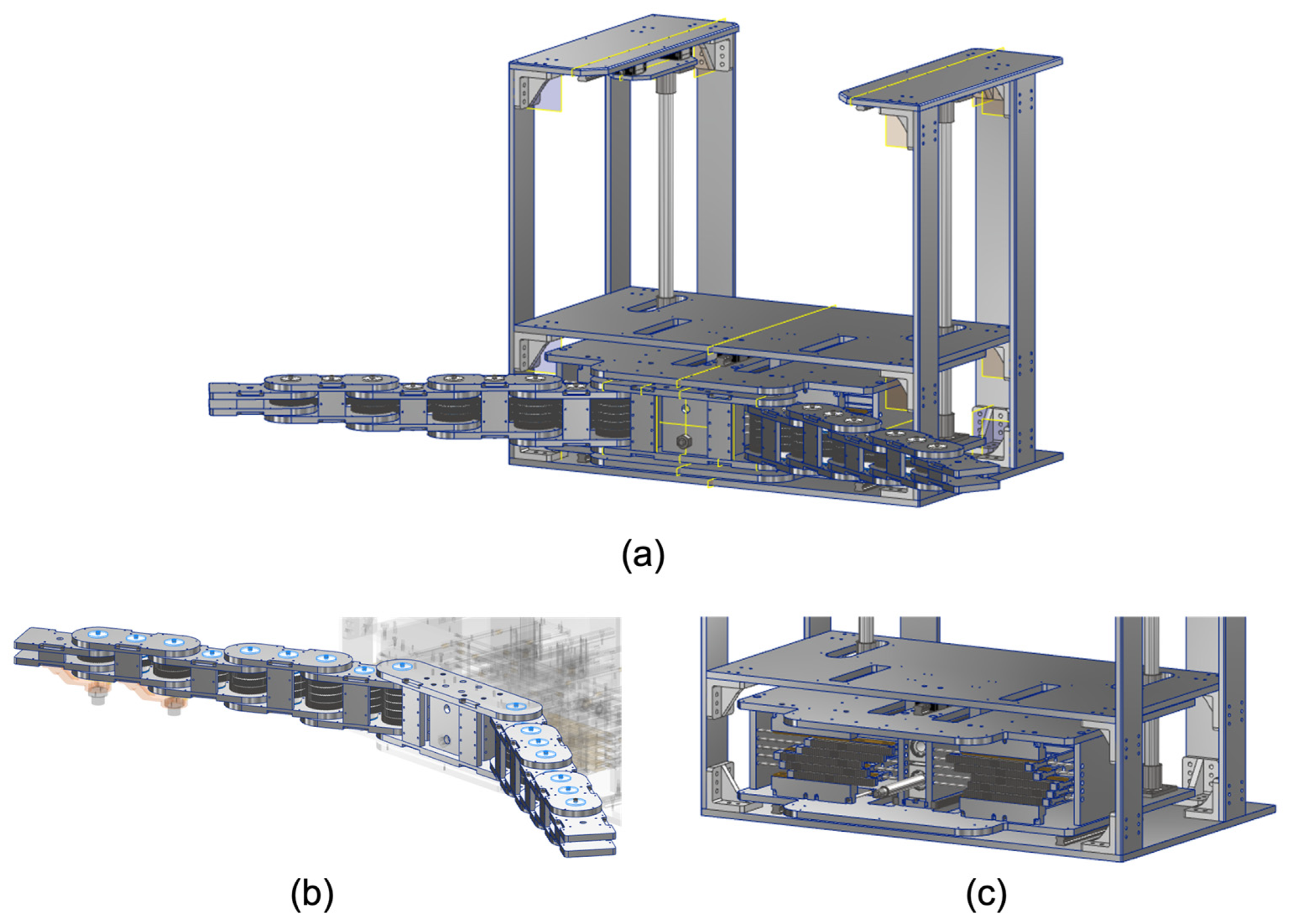
In order to obtain the heart and lung sounds comprehensively and efficiently, we propose a unique method of mechanically wrapping the patient’s chest and back with multiple acoustic sensors, like a hug with both arms, without the use of any actuators. The proposed mechanism consists of a twin-articulated arm with multi-layer gear coupling and a cam mechanism for power transmission, as shown in
Figure 2. The hugging motion is generated by pushing the cam mechanism with the driving forces of the patient such as self-weight. The force applied to the cam mechanism by the patient acts as the driving force for the twin-articulated arm. The trajectory of the twin-articulated arm varies depending on the distance of the push of the cam mechanism. The twin-articulated arm with multi-layer gear couplings and the cam mechanisms for power transmission are described in detail in the following sections.
2.3. Articulated Arm with Multi-Layer Gear Coupling
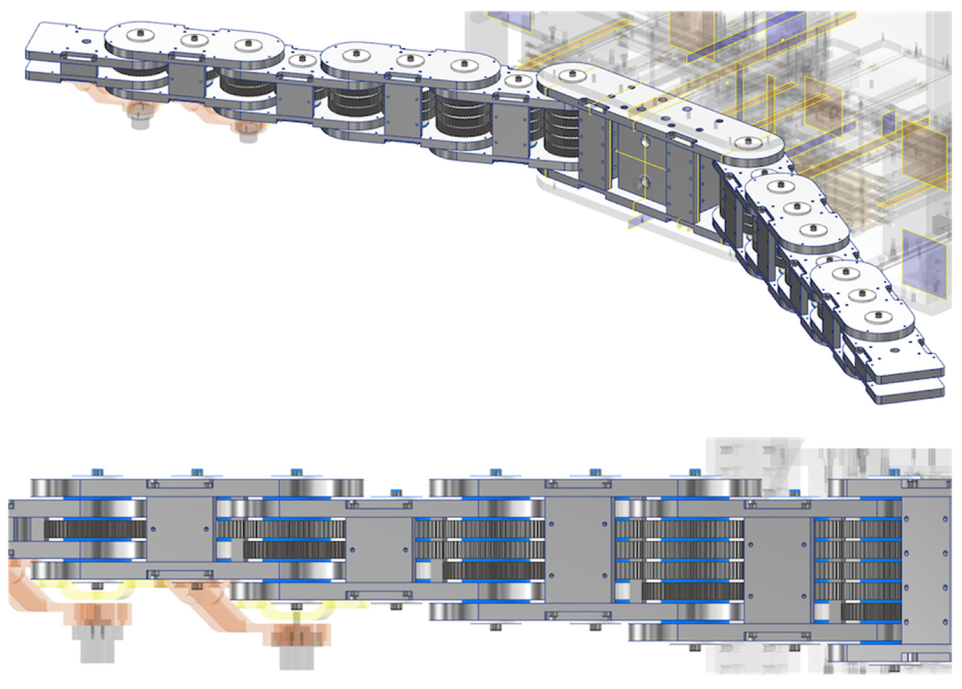
The role of the articulated arm is to wrap around the chest and back to accommodate individual differences in body shape. Therefore, it is necessary to be able to flexibly change the arm’s posture to fit various body shapes. The articulated arm consists of multiple layers of connected gears to provide high precision, smooth motion, and enhanced torque transmission. In each layer, the gears are connected by an odd number of gears. The adjacent gears are connected, so the rotation angle of the gear at the root is synchronized with that of the gear at the tip.
Figure 3 shows a conceptual illustration of the articulated arm with multi-layer gear coupling. In
Figure 3, the power transmission for each color gear corresponds to the rotation of each color link. For example, when rotating the yellow gear (rightmost) at the root, only the yellow link at the tip rotates, while when rotating the blue gear (second from left) at the root, only the blue link at the tip rotates. Thus, the angle of rotation of each link can be controlled by the angle of rotation of the gear at the root of each layer. Note that the motion of the articulated arm can be observed in a
Video S1 in the Supplementary Material. The developed articulated arm has a five-layer gear coupling, as shown in
Figure 4. The position coordinates of each joint (
xi,
yi) are obtained by the following equations:
L1–L5 and θ1–θ5 represent each link length and the rotational angle of the gear at the root of each layer. In this study, all the link lengths are fixed at 120 mm.
Resin gears are used to reduce the weight of the arm. The reason for this is that the rotation speed is unnecessary, and the load capacity of the resin gears is sufficient for this case. Meanwhile, the gears fixed to the links are made of stainless steel (SUS304) because of the keyway required. Resin spacers are also inserted between each gear to reduce resistance between the gears in the layer direction.
2.4. Cam Mechanism for Power Transmission
The desired operation of this system is that the patient can easily and safely operate the system under their own power. The role of the cam mechanism is to convert and transmit the pushing force from the patient to the driving force to transform the articulated arm. As mentioned above, each link of the articulated arm rotates in response to each root gear. In addition, to transform the arms into the specified arm posture, it is necessary to give the specified amount of rotation for each gear. Therefore, a mechanism is needed that can convert the pushing distance by the patient into a specified amount of rotation of each root gear.
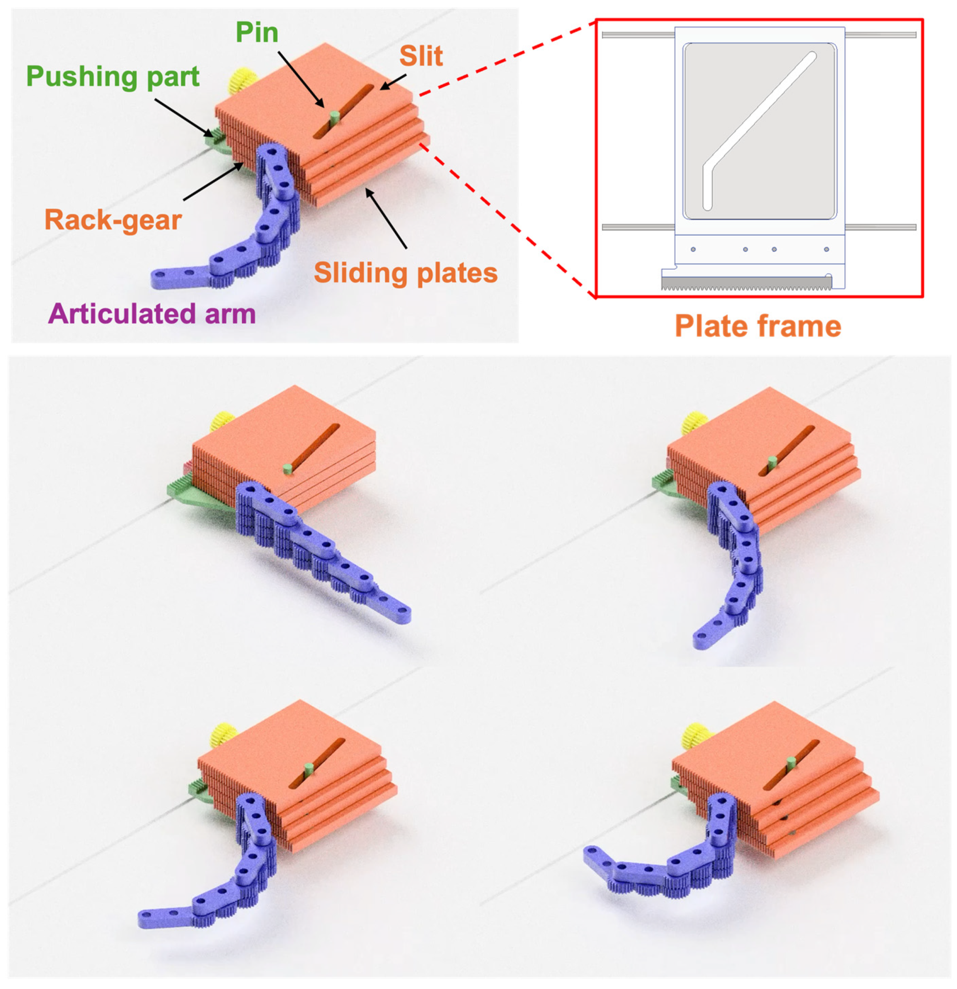
Figure 5 shows a conceptual illustration of the cam mechanism. The cam mechanism consists of slide plates with engraved slits and rack gears and a pushing part with a pin. Each sliding plate has a unique slit, and the pin penetrates through all those slits. The pin is firmly fixed to the pushing part, and the pushing force from the patient against the pushing part is converted into the sliding force of the sliding plates following the unique slit shape, which, in turn, is converted into the force to rotate the gears at the root of each layer via the attached rack-gear like a cam mechanism. The slope of the slit changes the distance the sliding plate slides in relation to the distance the pushing part is pressed. Thus, arbitrary arm trajectories can be generated by the pattern of slits in the sliding plates. Note that the synchronized motion of the cam mechanism and the articulated arm can be observed in a
Video S1 in the Supplementary Material.
Each slide plate is fixed to a plate frame supported by two linear shafts. An oilless bushing is inserted in the hole, through which the linear shaft passes to reduce resistance. The reason for not using a metal ball rolling linear bushing is to increase the diameter of the linear shaft. Also, to reduce the push-in amount by half, a planetary gear mechanism using a rack and pinion is employed in the pushing part.
2.5. Hugging Path Generation
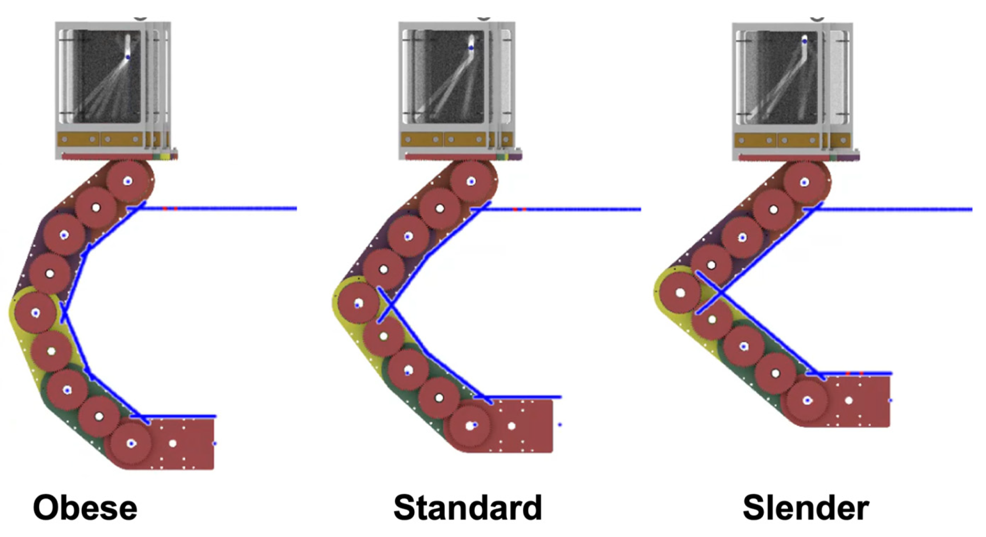
For hugging the patient’s body with the proposed mechanism, the individual differences in body size need to be considered. The articulated arm posture suitable for obese body types may result in a large gap between the arm and the body for slender body types, while the articulated arm posture suitable for slender body types may result in the articulated arm contacting the body for obese body types. In this study, we classified the body types into three major categories and made it possible to generate an arm posture suitable for each body shape with a single trajectory. Based on the statistical body dimension database [
30] on chest dimensions (width and thickness), we classified the body shapes into obese, standard, and slender, as shown in
Table 1. Note that the cross-section of the chest is regarded as an ellipse, and the width and the thickness of the chest correspond to the long axis and the short axis of the ellipse, respectively. For each body shape boundary ellipse, each joint angle was determined using our simulator so that the angle between the normal of each link and the normal at the intersection of the normal of each link and the ellipse was less than 20°, while the arm did not touch the body, as shown in
Figure 6. The experimentally derived rotation angles of each joint for each body type are shown in
Table 2. Each set of joint angles can generate the arm posture suitable for each body type. Then, in order to transform the articulated arm posture at the intended joint angles in one trajectory, we created a pattern of slits in the sliding plates, as shown in
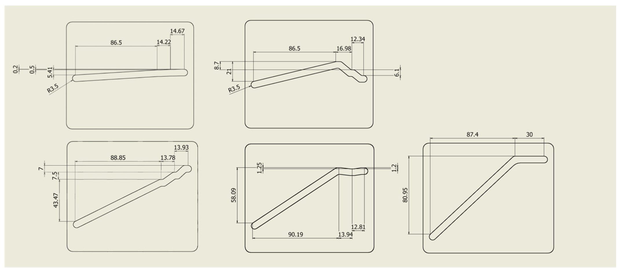
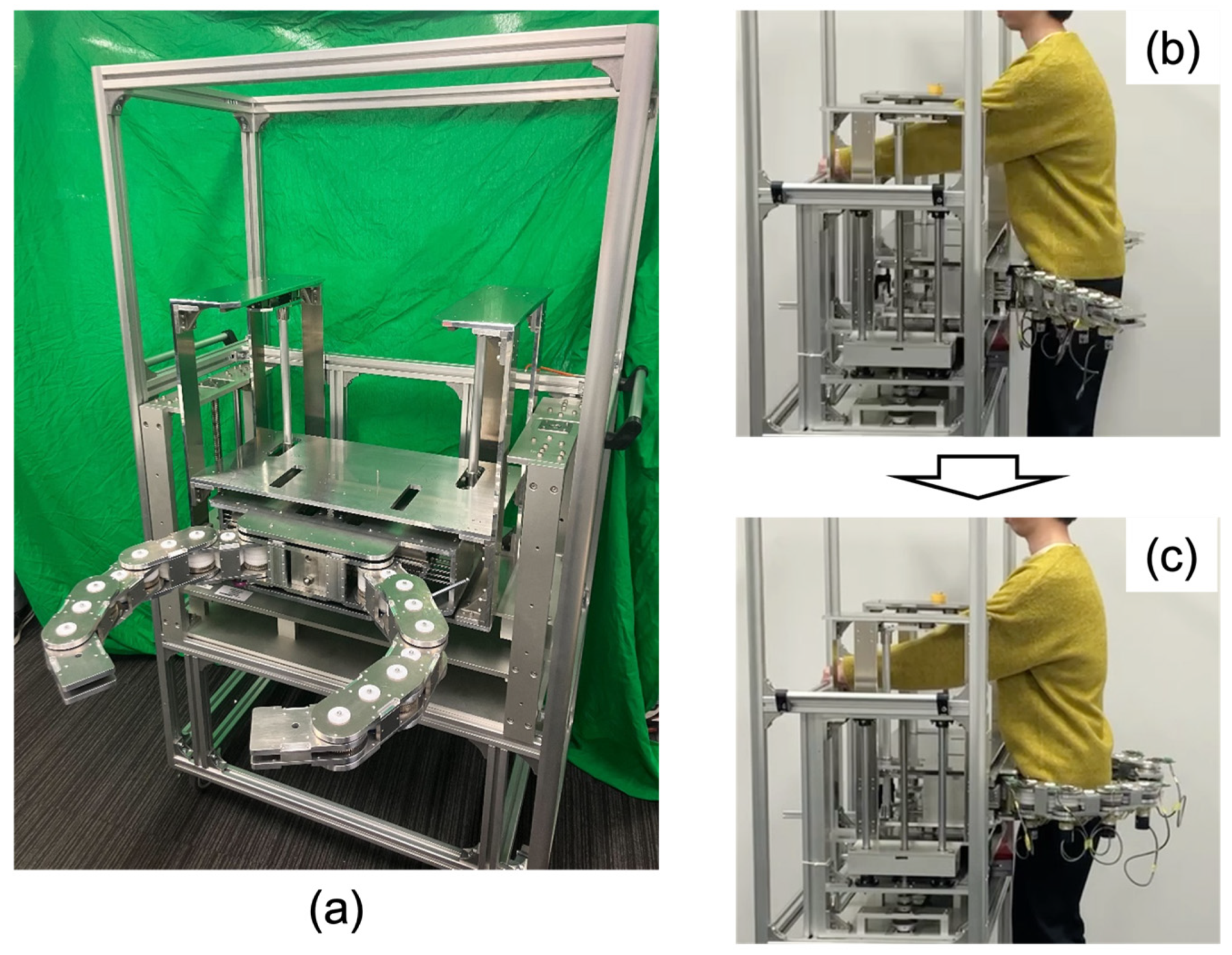
Figure 7. This configuration enables the generation of the articulated arm posture suitable for obese, standard, and slender body types sequentially corresponding to the distance of the pin pushing. Finally, the total assembled hugging mechanism is shown in
Figure 8.
3. Results
For evaluating the accuracy of the hugging mechanism, we measured the positioning error of the articulated arm after pushing the cam mechanism. Incremental encoders (RE2AR3ML, Omron, Kyoto, Japan) were implemented into each joint for calculating the positioning error, as shown in
Figure 9. With the encoders connected to encoder counters (SKU 8358, Switch Science, Tokyo, Japan), each joint angle was calculated. The pose of the articulated arm could be calculated with each link length and each joint angle. The measured positions were a side plate mounted on the first link of the arm and a back plate mounted on fifth link of the arm. The side plate mounted the acoustic sensors for acquiring the sounds of the middle and lower lobes of the lung and mitral valve, and the back plate mounted the acoustic sensors for acquiring the sounds of the upper and lower lobes of the lung. By comparing the ideal position calculated by the simulator with the actual position measured by the encoder, the angular error of each joint and the position error of the side and back plates when transformed for each body type (obese, standard, and slender) were calculated. The position error was calculated with the Euclidean distance between them. As for the statistical analysis, Student’s two-tailed
t-test with a 90% confidence interval was used to determine if there were significant differences in the position error between the side and back plates. Twelve trials were performed in each condition.
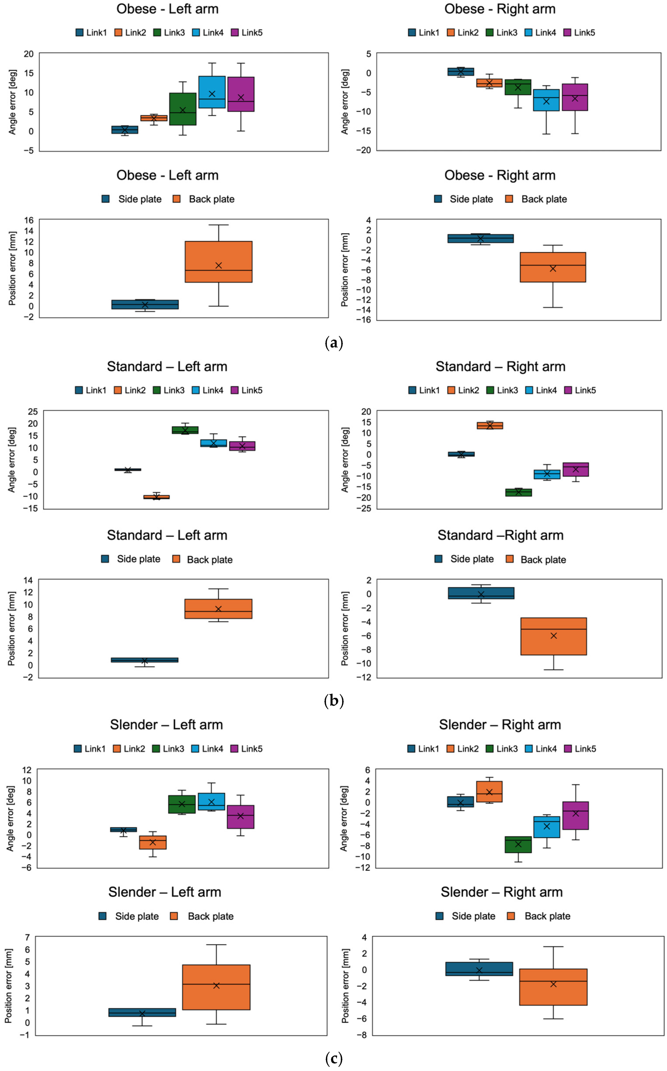
The results of the angular errors of each arm joint and the position errors of the side and back plates for each body type (obese, standard, and slender) are shown in
Figure 10 and
Table 3 and
Table 4. In all conditions, the position errors were less than 15 mm. Also, comparing the left and right arms, the errors were symmetrical in each condition. Comparing the position errors of the side and back plates, the back plate was significantly larger than the side plate (
p < 0.05). This may be because the side plates were attached to the first link and were not affected by the angular error of each joint, whereas the error in the back plate was due to the cumulative angular error of all the joints because the back plate was attached to the fifth link.
Focusing on the angle error of each link joint, the error trends differed between the obese and standard/slender body types. In the obese body type, the error in the joint at the end of the arm increased. On the other hand, the angular error of the second link switched between positive and negative during the transition from obese to standard. In the standard body type, the angular errors of the second and third links were larger, while the fourth and fifth remained unchanged. In the slender body type, the angular error of any joint was less than in the standard body type. Focusing on the error of each joint angle in the standard body shape, the position error of the back plate was about 10 mm, despite the fact that the error was nearly 20°. This may be because the joint angle errors were reversed positively and negatively in the second and third links, which may have canceled each other out.
4. Discussion
The results demonstrate that the proposed hugging mechanism was able to be transformed for each body type (obese, standard, and slender). The advantage of the proposed hugging mechanism is that it does not use an actuator, so the possibility of the hugging mechanism harming the patient due to actuator or sensor failure is minimized. To the best of our knowledge, this is the first actuator-less robotic auscultation system. Previous robotic auscultation systems utilized a cooperative robot arm to place the stethoscope [
25,
26,
27,
28,
29]. The advantage of those systems is that they can place the stethoscope at the auscultation position accurately with AI-based object detection and auscultation position estimation. In addition, the use of commercial, inexpensive cooperative robot arms may reduce costs. Meanwhile, the procedure time is longer. Zhu et al. [
26] reported that the total procedure time with robotic auscultation was around 10 min, but our mechanism took a few seconds to wrap around the chest and back. Although our system does not implement a function for acquiring auscultatory sounds yet, the acquisition time with a multi-sensor array will be less than 1 min. Therefore, we assume that the proposed system has an advantage in terms of safety and efficiency compared to previous robotic auscultation systems.
On the other hand, the issue of positional error remains. A possible reason for angular errors in the joints of both arms could be gear backlash. The proposed mechanism consists of a lot of gears. The accumulation of gear backlash in all joints may cause some positional errors. In particular, the direction of rotation of some gears was reversed during the transition from the obese to the standard body shape, so it is assumed that the backlash effect was significant. In addition, friction can occur between the pin and the slit in the cam mechanism. Since the force applied by the patient is concentrated on the pin and the pin contacts the multilayer sliding plate from various angles, the friction between the pin and the slit is expected to be high. The increased friction may decrease the smoothness of the hugging motion and may cause some deflection of mechanical components. This is a limitation of a mechanical approach without electrical control. Although the positional errors in each body type were less than 15 mm, it is necessary to further investigate if the positional error is acceptable for clinical application. In general auscultation, a positional error of the stethoscope of 15 mm may not affect the sound quality of auscultation. As shown in
Figure 1, our final design integrates a multi-acoustic sensor array into the proposed hugging mechanism. By achieving this, the multi-acoustic sensor array may be able to compensate for the potential effect of positional errors in the hugging mechanism on sound quality.
In this study, the corresponding body shapes were tentatively classified into three categories, but it is possible to further subdivide them. Also, the body dimension database used in this study is based on the data of Japanese adults. Body dimensions vary by region of the country, between men and women, and between adults and children. Arbitrary articulated arm postures need to be generated by modifying the slit pattern on the cam mechanism according to the classification of the targeted body type. Also, the length of each link was experimentally fixed at 120 mm and the number of joints at five, but those parameters can be optimized.
A limitation of this study is that it did not implement a function to automatically classify a patient’s body type. The hugging mechanism needs to limit the range of movement of the pin in the slit corresponding to the body type. It will be necessary to implement a non-contact and seamless system for estimating chest circumference, such as using an RGB-D camera. For instance, there is a study that carried out body weight and circumference estimation with AI and an RGB-D camera data [
31,
32].
In addition, the lack of human testing is a major limitation. The evaluation of usability, comfort, and accuracy is essential in clinical applications. In addition to the aforementioned evaluation indices, the quality of the auscultatory sound obtained by the proposed system is also an important evaluation index for clinical validation; therefore, we are considering conducting human trials after integrating the hugging mechanism and the multi-acoustic sensor array described in
Section 2.1. Experiments with a large number of subjects will be performed to verify the validity of the three body shape classifications, the allowable pushing force required to operate the hugging mechanism, and the diagnostic accuracy of the auscultatory sounds obtained by the robot.
5. Conclusions
In conclusion, this study proposes a unique actuator-less hugging mechanism, aiming toward a robot-assisted auscultation system capable of safely acquiring chest and back auscultatory sounds simultaneously. The hugging mechanism consists of a twin-articulated arm with multi-layer gear coupling and a cam mechanism for power transmission, and it can be transformed to wrap around the chest and back to fit the patient’s body shape with only the patients’ pushing force without using any actuators. The advantage of not using actuators is that the possibility of the hugging mechanism harming the patient due to actuator or sensor failure is minimized. The experimental results demonstrate that the proposed hugging mechanism was able to be transformed for each body type (obese, standard, and slender), and its positional error was less than 15 mm in all body types. Although it is necessary to further investigate if the remaining errors are critical, the possible reason for the positional errors could be gear backlash. The accumulation of gear backlash in all joints may cause some positional errors, suggesting the limitations of a mechanical approach without electrical control.
For future work, integration of the proposed hugging mechanism and a multi-acoustic sensor array and conducting a human trial with the integrated system are essential. In order to verify the optimal body type classification and the optimal design parameters, such as the number of links and the length of the articulated arm in the hugging mechanism, a more comprehensive collection and analysis of human data with the integrated system will be required. In addition, an improved smoothness of operation is also important from the standpoint of versatility for actual clinical operation.
Author Contributions
Conceptualization, R.T., T.O., K.Y. and H.I.; methodology, R.T., T.O., R.U., and R.B.; software, T.O. and R.B.; validation, R.T, T.O. and R.U.; formal analysis, R.T. and T.O.; investigation, R.T., T.O., H.I. and K.Y.; resources, R.T., H.I. and K.Y.; writing, R.T.; supervision, H.I., Y.M. and K.Y.; funding acquisition, R.T. All authors have read and agreed to the published version of the manuscript.
Funding
This research was supported in part by the JSPS KAKENHI [Grants-in-Aid for Scientific Research] (grant number 22K18225).
Institutional Review Board Statement
Not applicable.
Informed Consent Statement
Not applicable.
Data Availability Statement
The original contributions presented in the study are included in the article, further inquiries can be directed to the corresponding author.
Conflicts of Interest
The authors declare no conflicts of interest.
References
- Pereira, D.; Castro, A.; Gomes, P.; Areias, J.C.N.C.; Reis, Z.S.N.; Coimbra, M.T.; Cruz-Correia, R. Digital Auscultation: Challenges and Perspectives. In Encyclopedia of E-Health and Telemedicine; IGI Global: Hershey, PA, USA, 2016; pp. 910–927. [Google Scholar] [CrossRef]
- Bennett, J.E.; Stevens, G.A.; Mathers, C.D.; Bonita, R.; Rehm, J.; Kruk, M.E.; Riley, L.M.; Dain, K.; Kengne, A.P.; Chalkidou, K.; et al. NCD Countdown 2030: Worldwide trends in non-communicable disease mortality and progress towards Sustainable Development Goal target 3.4. Lancet 2018, 392, 1072–1088. [Google Scholar] [CrossRef] [PubMed]
- Kim, Y.; Hyon, Y.; Jung, S.S.; Lee, S.; Yoo, G. Respiratory sound classification for crackles, wheezes, and rhonchi in the clinical field using deep learning. Sci. Rep. 2021, 11, 17186. [Google Scholar] [CrossRef] [PubMed]
- Chorba, J.S.; Shapiro, A.M.; Le, L.; Maidens, J.; Prince, J.; Pham, S.; Kanzawa, M.M.; Barbosa, D.N.; Currie, C.; Brooks, C.; et al. Deep Learning Algorithm for Automated Cardiac Murmur Detection via a Digital Stethoscope Platform. J. Am. Heart Assoc. 2021, 10, e019905. [Google Scholar] [CrossRef] [PubMed]
- Jiang, Z.; Song, W.; Yan, Y.; Li, A.; Shen, Y.; Lu, S.; Lv, T.; Li, X.; Li, T.; Zhang, X.; et al. Automated valvular heart disease detection using heart sound with a deep learning algorithm. Int. J. Cardiol. Heart Vasc. 2024, 51, 101368. [Google Scholar] [CrossRef] [PubMed]
- Kevat, A.; Kalirajah, A.; Roseby, R. Artificial intelligence accuracy in detecting pathological breath sounds in children using digital stethoscopes. Respir. Res. 2020, 21, 4–9. [Google Scholar] [CrossRef]
- Kraman, S.S. Transmission of lung sounds through light clothing. Respiration 2008, 75, 85–88. [Google Scholar] [CrossRef]
- Deloughery, E.P. The Female Patient, the Male Physician, and the Inadequate Cardiac Exam. Acad. Med. 2018, 93, 1100. [Google Scholar] [CrossRef]
- Li, K.; Xu, Y.; Meng, M.Q.H. An Overview of Systems and Techniques for Autonomous Robotic Ultrasound Acquisitions. IEEE Trans. Med. Robot. Bionics 2021, 3, 510–524. [Google Scholar] [CrossRef]
- von Haxthausen, F.; Böttger, S.; Wulff, D.; Hagenah, J.; García-Vázquez, V.; Ipsen, S. Medical Robotics for Ultrasound Imaging: Current Systems and Future Trends. Curr. Robot. Rep. 2021, 2, 55–71. [Google Scholar] [CrossRef]
- Shida, Y.; Kumagai, S.; Tsumura, R.; Iwata, H. Automated Image Acquisition of Parasternal Long-Axis View with Robotic Echocardiography. IEEE Robot. Autom. Lett. 2023, 8, 5228–5235. [Google Scholar] [CrossRef]
- Giuliani, M.; Szczęśniak-Stańczyk, D.; Mirnig, N.; Stollnberger, G.; Szyszko, M.; Stańczyk, B.; Tscheligi, M. User-centred design and evaluation of a tele-operated echocardiography robot. Health Technol. 2020, 10, 649–665. [Google Scholar] [CrossRef]
- Housden, J.; Wang, S.; Bao, X.; Zheng, J.; Skelton, E.; Matthew, J.; Noh, Y.; Eltiraifi, O.; Singh, A.; Singh, D.; et al. Towards Standardized Acquisition with a Dual-probe Ultrasound Robot for Fetal Imaging. IEEE Robot. Autom. Lett. 2021, 6, 1059–1065. [Google Scholar] [CrossRef] [PubMed]
- Tsumura, R.; Iwata, H. Robotic fetal ultrasonography platform with a passive scan mechanism. Int. J. Comput. Assist. Radiol. Surg. 2020, 15, 1323–1333. [Google Scholar] [CrossRef] [PubMed]
- Wang, S.; Housden, J.; Noh, Y.; Singh, D.; Singh, A.; Skelton, E.; Matthew, J.; Tan, C.; Back, J.; Lindenroth, L.; et al. Robotic-Assisted Ultrasound for Fetal Imaging: Evolution from Single-Arm to Dual-Arm System; Springer International Publishing: Cham, Switzerland, 2019; Volume 11650, pp. 27–38. [Google Scholar]
- Arbeille, P.; Ruiz, J.; Herve, P.; Chevillot, M.; Poisson, G.; Perrotin, F. Fetal tele-echography using a robotic arm and a satellite link. Ultrasound Obstet. Gynecol. 2005, 26, 221–226. [Google Scholar] [CrossRef]
- Ipsen, S.; Wulff, D.; Kuhlemann, I.; Schweikard, A.; Ernst, F. Towards automated ultrasound imaging—Robotic image acquisition in liver and prostate for long-term motion monitoring. Phys. Med. Biol. 2021, 66, 094002. [Google Scholar] [CrossRef]
- Mustafa, A.S.B.; Ishii, T.; Matsunaga, Y.; Nakadate, R.; Ishii, H.; Ogawa, K.; Saito, A.; Sugawara, M.; Niki, K.; Takanishi, A. Development of robotic system for autonomous liver screening using ultrasound scanning device. In Proceedings of the 2013 IEEE International Conference on Robotics and Biomimetics, Shenzhen, China, 12–14 December 2013; pp. 804–809. [Google Scholar] [CrossRef]
- Gazali, N.A.; Abu Bakar, R.; Tan, C.I.C.; Bo, J.; Lee, S.H.E.; Ho, H.P.; Lim, S.Y.; Cheong, W.K.; Jennifer Liaw, S.C.; Ooi, C.C. Comparing conventional abdominal ultrasound scanning versus a ROBotic assisted UltraSonography sysTem (ROBUST). WFUMB Ultrasound Open 2024, 2, 100040. [Google Scholar] [CrossRef]
- Arbeille, P.; Capri, A.; Ayoub, J.; Kieffer, V.; Georgescu, M.; Poisson, G. Use of a robotic arm to perform remote abdominal telesonography. AJR Am. J. Roentgenol. 2007, 188, W317–W322. [Google Scholar] [CrossRef]
- Huang, Y.; Xiao, W.; Wang, C.; Liu, H.; Huang, R.; Sun, Z. Towards Fully Autonomous Ultrasound Scanning Robot with Imitation Learning Based on Clinical Protocols. IEEE Robot. Autom. Lett. 2021, 6, 3671–3678. [Google Scholar] [CrossRef]
- Ito, K.; Sugano, S.; Iwata, H. Portable and attachable tele-echography robot system: FASTele. In Proceedings of the 2010 Annual International Conference of the IEEE Engineering in Medicine and Biology Society, EMBC’10, Buenos Aires, Argentina, 31 August–4 September 2010; pp. 487–490. [Google Scholar] [CrossRef]
- Ye, R.; Zhou, X.; Shao, F.; Xiong, L.; Hong, J.; Huang, H.; Tong, W.; Wang, J.; Chen, S.; Cui, A.; et al. Feasibility of a 5G-Based Robot-Assisted Remote Ultrasound System for Cardiopulmonary Assessment of Patients With COVID-19. Chest 2020, in press. [Google Scholar] [CrossRef]
- Tsumura, R.; Hardin, J.W.; Bimbraw, K.; Grossestreuer, A.V.; Odusanya, O.S.; Zheng, Y.; Hill, J.C.; Hoffmann, B.; Soboyejo, W.; Zhang, H.K. Tele-Operative Low-Cost Robotic Lung Ultrasound Scanning Platform for Triage of COVID-19 Patients. IEEE Robot. Autom. Lett. 2021, 6, 4664–4671. [Google Scholar] [CrossRef]
- Falleni, S.; Filippeschi, A.; Ruffaldi, E.; Avizzano, C.A. Teleoperated multimodal robotic interface for telemedicine: A case study on remote auscultation. In Proceedings of the RO-MAN 2017—26th IEEE International Symposium on Robot and Human Interactive Communication, Lisbon, Portugal, 28 August–1 September 2017; pp. 476–482. [Google Scholar] [CrossRef]
- Zhu, Y.; Smith, A.; Hauser, K. Automated Heart and Lung Auscultation in Robotic Physical Examinations. IEEE Robot. Autom. Lett. 2022, 7, 4204–4211. [Google Scholar] [CrossRef]
- Lopes, D.; Coelho, L.; Silva, M.F. Development of a Collaborative Robotic Platform for Autonomous Auscultation. Appl. Sci. 2023, 13, 1604. [Google Scholar] [CrossRef]
- Tsumura, R.; Koseki, Y.; Nitta, N.; Yoshinaka, K. Towards fully automated robotic platform for remote auscultation. Int. J. Med. Robot. 2022, 19, e2461. [Google Scholar] [CrossRef]
- Tsumura, R.; Umezawa, A.; Morishima, Y.; Iwata, H.; Yoshinaka, K. Suppression of Clothing-Induced Acoustic Attenuation in Robotic Auscultation. Sensors 2023, 23, 2260. [Google Scholar] [CrossRef] [PubMed]
- Kouchi, M.; Mochimaru, M. Japanese 3-D body shape and dimensions data 2003. Natl. Inst. Adv. Ind. Sci. 2003, H18PRO-503. [Google Scholar]
- Pfitzner, C.; May, S.; Nuchter, A. Body Weight Estimation for Dose-Finding and Health Monitoring of Lying, Standing and Walking Patients Based on RGB-D Data. Sensors 2018, 18, 1311. [Google Scholar] [CrossRef]
- Cherdchusakulchai, R.; Thoumrungroje, S.; Tungpanjasil, T.; Pimpin, A.; Srituravanich, W.; Damrongplasit, N. Contactless Body Measurement System Using Single Fixed-Point RGBD Camera Based on Pose Graph Reconstruction. IEEE Access 2024, 12, 84363–84373. [Google Scholar] [CrossRef]
Figure 1.
Final conceptual illustration of robotic auscultation. The robotic auscultation system enables wrapping the chest and back with the multi-acoustic sensor array by pushing the hugging mechanism. (a) The proposed system overview; (b) the entire process with the proposed system: (b) the patient approaches the system; (c) the patient stands in front of the hugging mechanism; (d) the patient pushed the hugging mechanism; (e) the patient is wrapped in the multi-acoustic sensor array and listened to for back and chest sounds.
Figure 2.
Components of (a) hugging mechanism: (b) articulated arm with multi-layer gear coupling and (c) cam mechanism for power transmission.
Figure 2.
Components of (a) hugging mechanism: (b) articulated arm with multi-layer gear coupling and (c) cam mechanism for power transmission.
Figure 3.
Multi-layer gear motion of articulated arm. The rotation of the root gear can deliver the rotation of each joint angle independently. Each color gear corresponds to each color rotating joint.
Figure 3.
Multi-layer gear motion of articulated arm. The rotation of the root gear can deliver the rotation of each joint angle independently. Each color gear corresponds to each color rotating joint.
Figure 4.
Overview of the articulated arm with multi-layered gear coupling. The blue parts between gears are resin spacers.
Figure 4.
Overview of the articulated arm with multi-layered gear coupling. The blue parts between gears are resin spacers.
Figure 5.
Conceptual illustration of the cam mechanism and the articulated arm. The cam mechanism consists of sliding plates with unique slits and rack gears and a pushing part with a pin. Each sliding plate has a unique slit, and the pin penetrates through all those slits. The pushing force from the patient against the pushing part is converted into the sliding force of the sliding plates following the unique slit shape.
Figure 6.
The trajectory generation fitting to various body shapes.
Figure 6.
The trajectory generation fitting to various body shapes.
Figure 7.
Detailed design of sliding plates.
Figure 7.
Detailed design of sliding plates.
Figure 8.
(a) Overview of developed hugging mechanism. (b) Before push, (c) after push.
Figure 8.
(a) Overview of developed hugging mechanism. (b) Before push, (c) after push.
Figure 9.
Experimental setup overview. Incremental encoders were implemented into each joint for calculating the positioning error. The measured positions were a side plate mounted on the first link of the arm and a back plate mounted on the fifth link of the arm.
Figure 9.
Experimental setup overview. Incremental encoders were implemented into each joint for calculating the positioning error. The measured positions were a side plate mounted on the first link of the arm and a back plate mounted on the fifth link of the arm.
Figure 10.
The results of the angle error of each joint and the position error of the side and back plates corresponding to (a) obese, (b) standard, and (c) slender.
Figure 10.
The results of the angle error of each joint and the position error of the side and back plates corresponding to (a) obese, (b) standard, and (c) slender.
Table 1.
Reference body shape dimensions.
Table 1.
Reference body shape dimensions.
| | Slender | Standard | Obese |
|---|
| Width [mm] | 213–251 | 251–288 | 288–333 |
| Thickness [mm] | 152–190 | 190–214 | 214–248 |
| Girth [mm] | 608–736 | 736–864 | 864–992 |
Table 2.
Theoretical values of joint angles required to generate the intended trajectory.
Table 2.
Theoretical values of joint angles required to generate the intended trajectory.
| | Joint Angle ° |
|---|
| θ1 | θ2 | θ3 | θ4 | θ5 |
|---|
| Obese | 40.23 | 29.70 | 42.42 | 27.46 | 40.19 |
| Standard | 41.22 | 12.05 | 73.42 | 15.52 | 37.79 |
| Slender | 41.68 | 0 | 98.28 | 0 | 40.04 |
Table 3.
Summary of angle errors of each joint corresponding to the body shapes.
Table 3.
Summary of angle errors of each joint corresponding to the body shapes.
| | | | Angle Error [deg] |
|---|
| | | 1 | 2 | 3 | 4 | 5 |
|---|
| Obese | Left | Avg. | 0.33 | 3.05 | 4.73 | 8.26 | 7.65 |
| | | Max. | 1.38 | 4.38 | 12.75 | 17.56 | 17.55 |
| | | Min. | −1.17 | 1.53 | −1.05 | 4.06 | 0 |
| | Right | Avg. | 0.42 | −2.81 | −2.85 | −6.39 | −5.38 |
| | | Max. | 1.47 | −0.33 | −1.65 | −3.31 | −1.20 |
| | | Min. | −1.08 | −4.08 | −9.15 | −15.91 | −15.75 |
| Standard | Left | Avg. | 0.87 | −10.78 | 16.53 | 10.96 | 10.20 |
| | | Max. | 1.32 | −8.53 | 20.19 | 15.76 | 14.55 |
| | | Min. | −0.33 | −11.35 | 15.54 | 10.21 | 8.25 |
| | Right | Avg. | −0.38 | 13.25 | −17.37 | −8.97 | −5.81 |
| | | Max. | 1.50 | 15.40 | −15.72 | −4.69 | −3.93 |
| | | Min. | −1.50 | 11.80 | −19.32 | −12.04 | −12.63 |
| Slender | Left | Avg. | −0.39 | 1.57 | −7.05 | −3.57 | −1.61 |
| | | Max. | 1.49 | 4.64 | −6.34 | −2.29 | 3.27 |
| | | Min. | −1.51 | −0.16 | −10.99 | −8.44 | −6.93 |
| | Right | Avg. | −0.39 | 1.56 | −7.01 | −3.57 | −1.61 |
| | | Max. | 1.49 | 4.64 | −6.34 | −2.29 | 3.27 |
| | | Min. | −1.51 | −0.16 | −10.99 | −8.44 | −6.93 |
Table 4.
Summary of position errors of side and back plates corresponding to the body shapes.
Table 4.
Summary of position errors of side and back plates corresponding to the body shapes.
| | | | Position Error [mm] |
|---|
| | | Side Plate | Back Plate |
|---|
| Obese | Left | Avg. | 0.29 | 6.66 |
| | | Max. | 1.20 | 15.0 |
| | | Min. | −1.02 | 0 |
| | Right | Avg. | 0.37 | 5.10 |
| | | Max. | 1.28 | −1.05 |
| | | Min. | −0.94 | −13.57 |
| Standard | Left | Avg. | 0.77 | 8.85 |
| | | Max. | 1.15 | 12.56 |
| | | Min. | −0.29 | 7.17 |
| | Right | Avg. | −0.33 | −5.05 |
| | | Max. | 1.31 | −3.43 |
| | | Min. | −1.31 | −10.93 |
| Slender | Left | Avg. | 0.78 | 3.15 |
| | | Max. | 1.16 | 6.40 |
| | | Min. | −0.28 | −0.13 |
| | Right | Avg. | −0.36 | −1.40 |
| | | Max. | 1.30 | 2.85 |
| | | Min. | −1.32 | −6.03 |
| Disclaimer/Publisher’s Note: The statements, opinions and data contained in all publications are solely those of the individual author(s) and contributor(s) and not of MDPI and/or the editor(s). MDPI and/or the editor(s) disclaim responsibility for any injury to people or property resulting from any ideas, methods, instructions or products referred to in the content. |
© 2025 by the authors. Licensee MDPI, Basel, Switzerland. This article is an open access article distributed under the terms and conditions of the Creative Commons Attribution (CC BY) license (https://creativecommons.org/licenses/by/4.0/).


 ,
, 


