Article

Experimental and Numerical Analysis of Ratcheting Behavior of Super Duplex SAF2507 Stainless Steel Under Uniaxial Loading

School of Control Engineering, Northeastern University, Qinhuangdao 066004, China
*
Author to whom correspondence should be addressed.
Appl. Sci. 2025, 15(3), 1424; https://doi.org/10.3390/app15031424
Submission received: 9 December 2024 / Revised: 23 January 2025 / Accepted: 27 January 2025 / Published: 30 January 2025
(This article belongs to the Section Materials Science and Engineering)

Abstract

:
Super duplex SAF2507 stainless steel is widely used in petrochemical piping systems during the transport of substances. The pipelines are subjected to cyclic loads due to road vibration and internal pressure, which causes the ratcheting behavior. In this research project, we conducted a battery of uniaxial ratcheting experiments of super duplex SAF2507 stainless steel under displacement cycling, and the effects of stress amplitude, mean stress, and pre-strain on the ratcheting strain were evaluated. The findings showed that ratcheting strain grew as mean stress and stress amplitude rose under identical stress conditions. Additionally, as pre-strain levels increased, the ratcheting strain was observed to diminish. In addition, a three-dimensional ratcheting boundary graph was created with stress amplitude, mean stress, and ratcheting strain rate. This represented a graphical surface area for the study of ratcheting strain rates for various combinations of mean stress and stress amplitude. A rate-independent model was developed by combining the Armstrong–Frederick (A-F) hardening rule with Ohno–Wang (O-W II) model, called the AF-OW II model. This constitutive model was implemented in the ABAQUS 2021 finite element software to numerically analyze the ratcheting evolution of SAF2507 stainless steel. The results indicated that the calculated results of the AF-OW II model closely aligned with the experimental data.

1. Introduction

Super duplex stainless steel SAF2507 is widely used in the oil and gas industries, especially in onshore pipelines and oil and gas transmission systems due to its excellent strength and corrosion resistance. In practical engineering applications, when pipelines were exposed to external cyclic loads, such as during the startup and shutdown of thermomechanical cycles, or when there were complex cyclic road vibrations, axial compressive strains in the pipeline could occur, with a gradual accumulation of plastic strains, resulting in a ratcheting effect that could seriously affect the safety and reliability of the components [1]. The study of the ratcheting behavior of SAF2507 stainless steel could be carried out using experimental analysis and the establishment of numerical calculation constitutive models to ensure the stable operation of the pipeline.
A large number of theoretical and experimental investigations into the ratcheting behavior of metals have been conducted. Yao et al. [2] studied how stress cycles and internal pressure influence the ratcheting behavior as well as the fatigue life of 1Cr18Ni10Ti tubing; Zhou and Xiong [3] studied the mechanical characteristics and ratcheting behavior of 316H steel; Chen et al. [4,5,6] carried out ratcheting experiments on S45C steel, 63Sn, and 37Pb solder, respectively, and paid special attention to the ratcheting behavior at various loading rates, analyzing the effects of cyclic load, cyclic stress rate, and loading sequence on the ratcheting effect of the materials, respectively; and Kang et al. [7,8] conducted uniaxial cyclic stress tests on heat-treated 42CrMo steel to investigate ratcheting strain and fatigue failure and their interaction. The construction of equipment pipelines and pressure vessels took into consideration the generation of ratcheting behavior [9,10,11,12]. Therefore, due to the limitations of the experimental information, it is equally important to discuss ratcheting strain theoretically.
Elastoplastic constitutive models could be divided into coupled [13] and uncoupled models [14,15]. The coupled class of models outperformed the uncoupled models in predicting ratcheting effects through the use of strain reinforcement and dynamic recovery terms and was widely used. The ratcheting effect of structures under diverse conditions requires a robust constitutive model, which can precisely express the mechanical response of materials subjected to cyclic loads. So far, many scholars have carried out a great deal of research work on this subject. For example, Chaboche [16,17,18,19] determined some classical cyclic constitutive models. Ohno [20,21] proposed the concept of the criticality of dynamic recovery, Yaguchi and Takahashi [22] proposed an improved Ohno–Wang model incorporating the tension-pressure asymmetry, and Bari [23] improved the kinematic hardening law, drawing inspiration from Delobelle’s ideas [24]. Ahmadzadeh and Varvani-Farahani [25,26] introduced the non-proportionality of the load into the normal vector of the yield surface. Okorokov [27] considered the Dirac delta function to model deviation effects, and Chen and Lang [28] and Abadie et al. [29] introduced viscoplastic flow rules into the kinematic hardening model. Chen [30] applied the OW-I rate-independent model to study the ratcheting behavior of S30408, Jiao [31] adopted a double-surface nonlinear kinematic hardening rate-independent model to analyze the ratcheting behavior of SAF2507 pipelines, and Chen [32] utilized the A-V rate-independent model to simulate the ratcheting effect of the austenitic stainless steel Z2CND18.12N pipelines. Numerous researchers [33,34,35,36] also revised constitutive models by relating various parameters. The new constitutive model [37,38] was embedded by the researchers into a simulation software to predict ratcheting deformation, which produced good simulation results.
The paper is organized into four main sections. Section 2 described the ratcheting experimental procedure. Section 3 discussed and analyzed the ratcheting experiments and determined the ratcheting boundary for SAF2507 steel. Section 4 implemented the AF-OW II model with isotropic hardening law into ABAQUS software. The model parameters were determined. The mixed model’s predictive capacity was validated through the comparison between experimental data and simulation outcomes. In the end, the contents of this study were summarized.

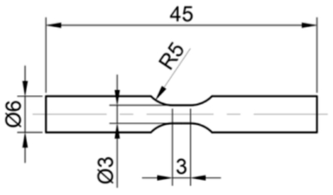
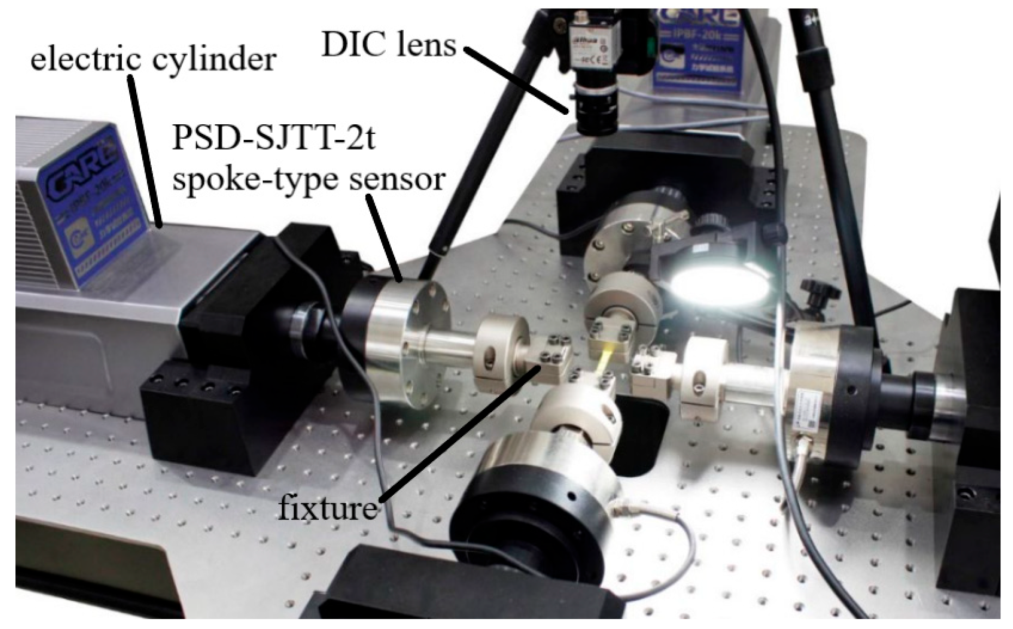
2. Ratcheting Experiments

The object of study in this paper was super duplex SAF2507 stainless steel, whose chemical composition was shown in Table 1. The raw material was a round bar with a diameter of 6 mm. The original bars were programmed and machined by a CNC lathe in accordance with ISO 12106 (Metallic materials—Fatigue testing—Axial-strain-controlled method) [39] and then went through a grinding treatment. Finally, the specimens shown in Figure 1 were obtained.
The experiments herein are carried out on the IPBF-20 k in situ biaxial mechanical testing system comprising four electric cylinders and symmetrically, orthogonally arranged motors. It has a variety of control modes, including biaxial synchronous control, biaxial asynchronous control, and uniaxial control. The control utilizes an advanced DSP, and the data acquisition system has a rotary encoder. With a 20 KN max load, it offers sinusoidal, triangular, and square waveforms and load, displacement, and strain control. The ratcheting test uses load control with a triangular wave for a constant loading rate. The tensile test uses displacement control. Paired with the NDDS-04 non-contact video extensometer system, which consists of a CCD, lens, etc., it can calculate multiple specimen parameters without material or environmental limitations, especially useful for micro-materials and in extreme temperatures. These features meet the requirements for conducting uniaxial ratcheting tests on materials, enabling the acquisition of precise results through uniaxial ratcheting experiments. The installation diagram is in Figure 2.
The loading conditions of uniaxial ratcheting test of SAF2507 stainless steel were shown in Table 2. The stress waveform under control was triangular. The ratcheting strain was defined as shown in Equation (1).
ε r = ε max + ε min / 2
where ε max denoted the maximum strain in a cycle and ε min denoted the minimum strain in a cycle. We additionally defined the incremental ratcheting strain within each cycle as the ratcheting strain rate, which was denoted by d ε r / d N , where N was the number of cycles.

3. Experimental Results and Discussion

The loading path schematic of uniaxial ratcheting experiment of SAF2507 stainless steel was displayed in Figure 3a with a mean stress of 500 MPa and a stress amplitude of 300 MPa. Figure 3b illustrated the stress–strain hysteresis loop. It observed clearly an unclosed stress–strain hysteresis loop. Figure 3c gave the relationship of the ratcheting strain and number of cycles. The ratcheting strain rate was given in Figure 3d.

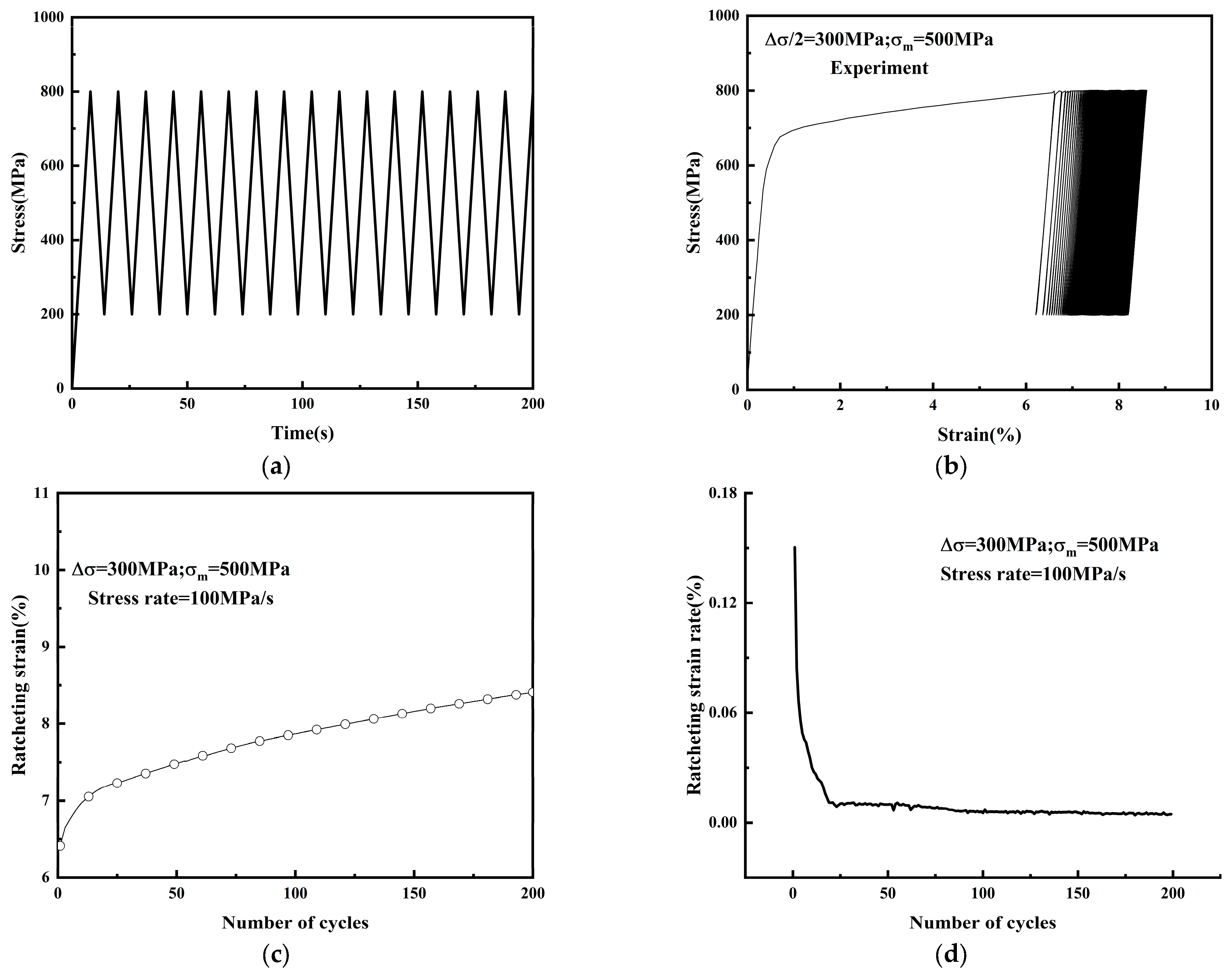
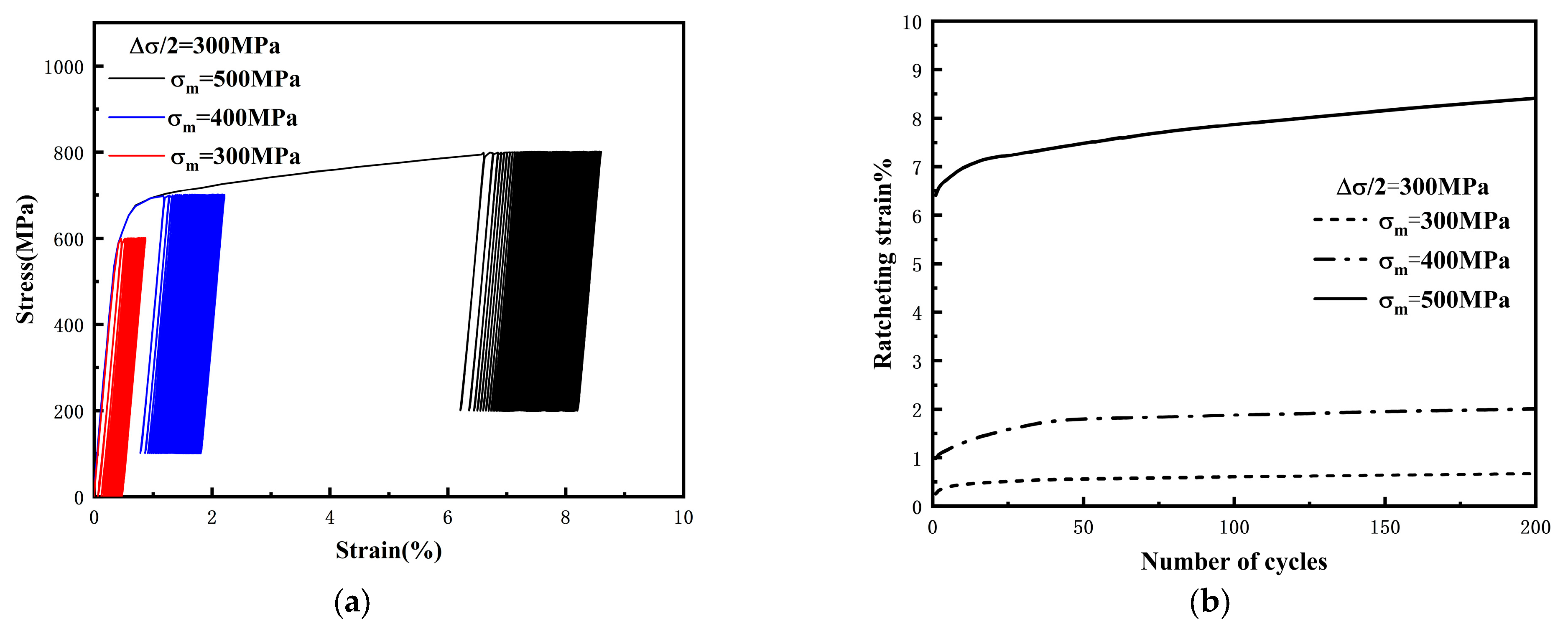
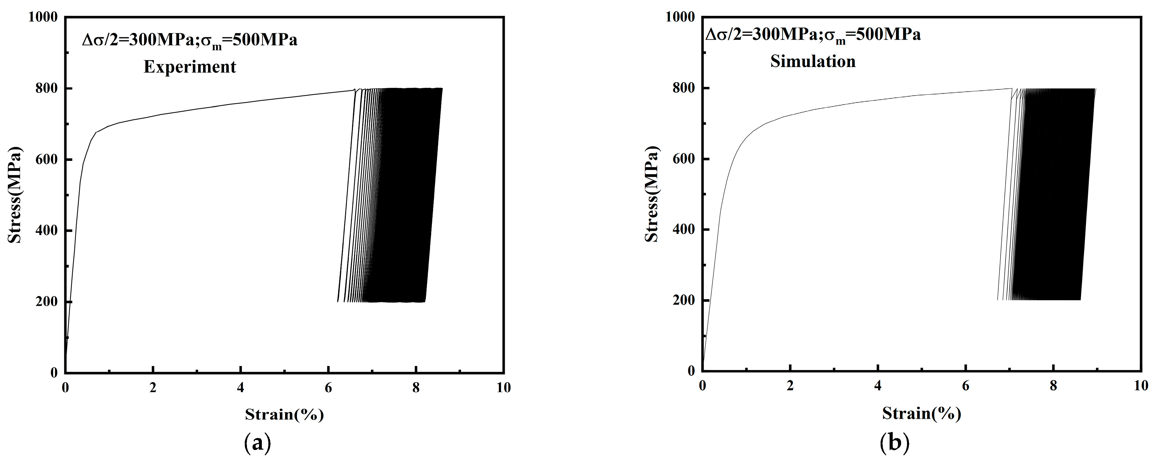
3.1. Influence of Mean Stress on Ratcheting Effect

In order to investigate the effect of mean stress on ratcheting behavior, Figure 4 shows the uniaxial ratcheting behavior of SAF2507 stainless steel at stress amplitude of 300 MPa and mean stresses of 300 MPa, 350 MPa, and 400 MPa. The stress–strain hysteresis loops for different loading conditions are given in Figure 4a. Figure 4b shows that the ratcheting strain initially increased rapidly but then transitioned to a slow growth phase where the ratcheting strain rate stabilized. For a given stress amplitude, an elevation in mean stress led to an increase in ratcheting strain, Chen [40] and Li [41] all discovered this result through ratcheting experiments on materials.

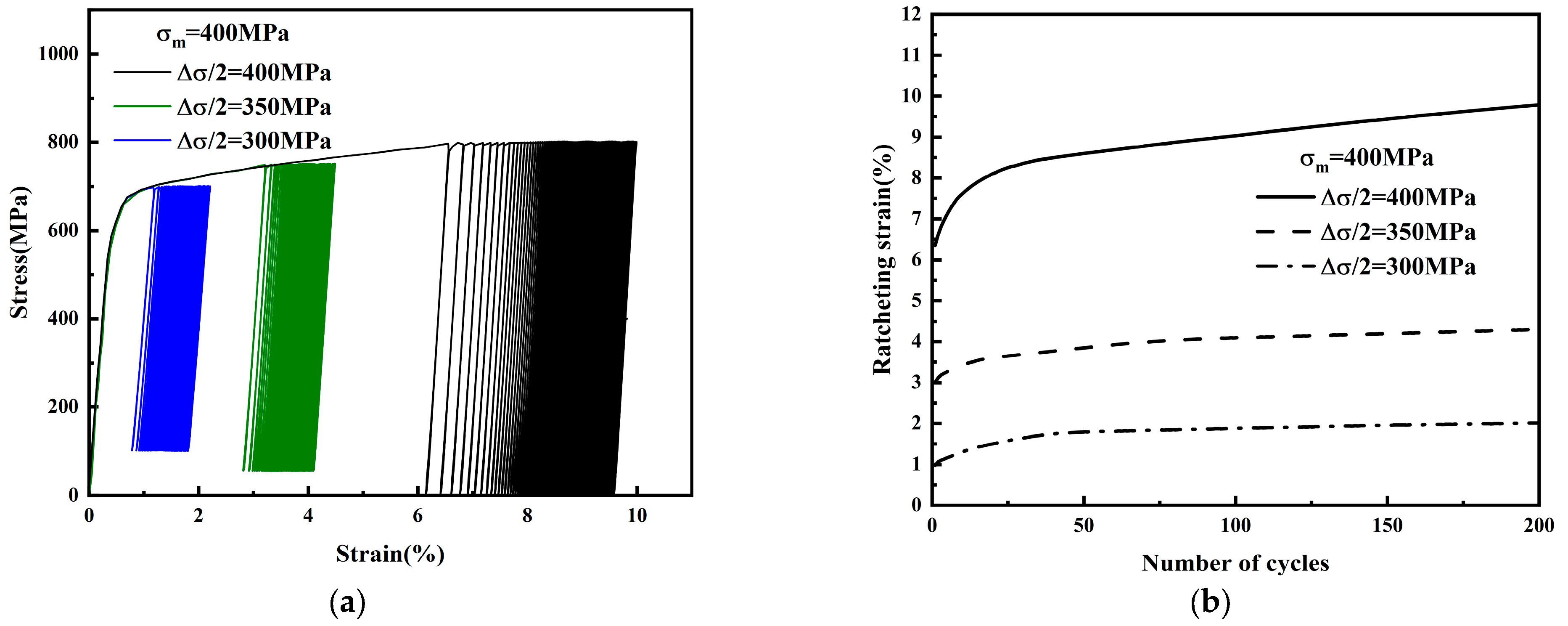
3.2. Influence of Stress Amplitude on Ratcheting Effect

The stress–strain hysteresis loops and the uniaxial ratcheting strain evolution of SAF2507 stainless steel at a constant mean stress of 400 MPa and different stress amplitudes (300, 350, and 400 MPa) are given in Figure 5. Figure 5 shows that the ratcheting strain increased with increasing stress amplitude under the same mean stress. Figure 5 shows that, similar to the results obtained by Chen [30] and Kang [8], the ratcheting strain increased with increasing stress amplitude under the same mean stress.

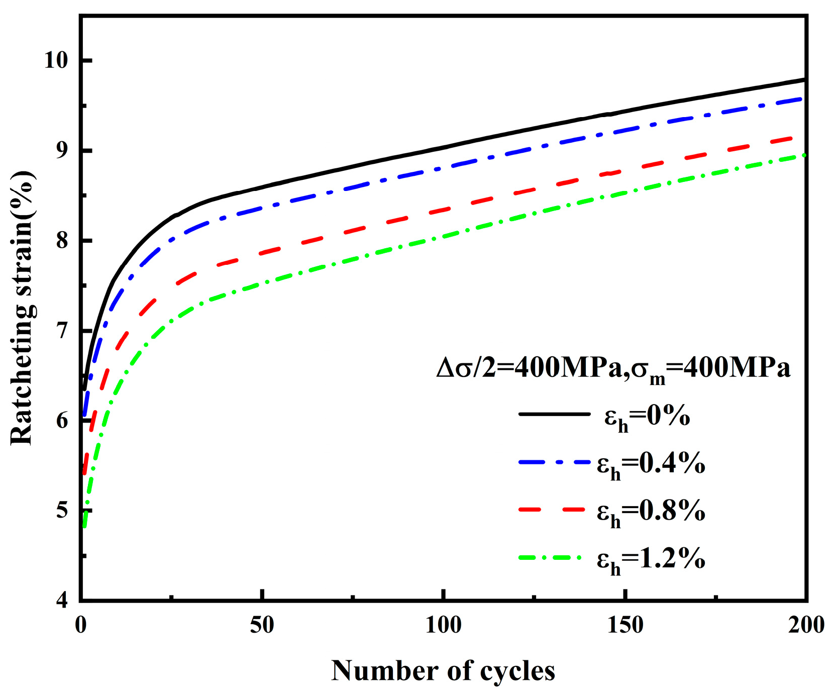
3.3. Influence of Pre-Strain on the Ratcheting Effect

Figure 6 shows the relationship of ratcheting strain with the number of cycles at both mean stress and stress amplitude of 400 MPa with different pre-strain (0, 0.4%, 0.8%, and 1.2%). It is evident from Figure 6 that the ratcheting strain decreased with the increase the amount of pre-strain. Both Wang [42] and Tripathy [43] discovered this phenomenon, which might be due to the fact that the complex dislocation structures formed during the pre-straining process are difficult to eliminate in the subsequent cycling process. Therefore, tensile pre-straining inhibits the accumulation of plastic strain [12].

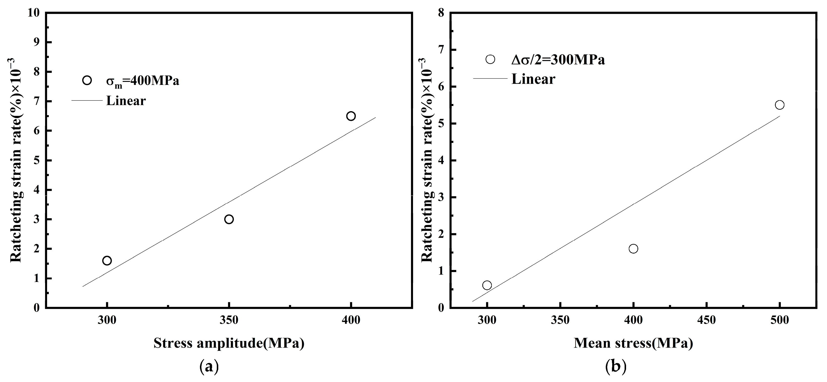
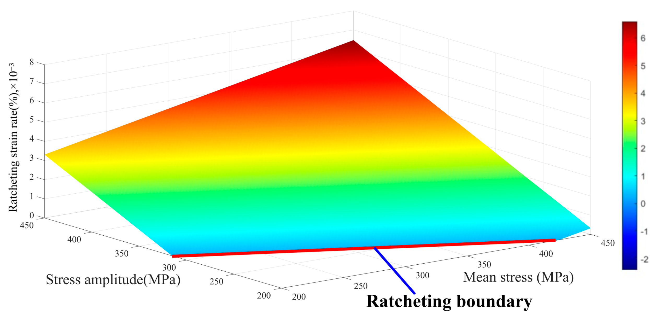
3.4. Ratcheting Strain Rate and Ratcheting Boundary for SAF2507 Steel

In order to arrest the ratcheting behavior of the material, Chen et al. [40] attempted to determine zero ratcheting strain rate with specified mean stress and stress amplitude. If the material was loaded under zero ratcheting strain rate conditions with specified mean stress and stress amplitude, ratcheting strain could be suppressed and would not increase further. The ratcheting strain rate represented the incremental ratcheting strain during each cycle and was denoted by d ε r / d N , where N was the number of cycle weeks.
Figure 7a showed the correlation between stress amplitude and ratcheting strain rate at a constant mean stress of 400 MPa. The correlation between the ratcheting strain rate and the mean stress at a constant stress amplitude of 300 MPa are shown in Figure 7b. Based on the least squares method, Equation (2) is used to regress. The slope and vertical intercept of Equation (2) are listed in Table 3, and the corresponding mean stress and stress amplitude were calculated when the ratcheting strain rate was zero, as shown in Table 3.
y = m x + c
The ratcheting effect was significantly impacted by both mean stress and stress amplitude. Chen et al. [40] provided the correlation among the ratcheting strain rate, the constant mean stress accompanied by the varying stress amplitude, and the constant stress amplitude along with the varying mean stress, which is presented in Equation (3).
ε ˙ r = m 1 a 1 + m 2 a 2 + c 1 + c 2 / 2
where the parameter m 1 denoted the slope of the stress amplitude and material ratcheting strain rate at constant mean stress, and the parameter m 2 denoted the slope of the mean stress and material ratcheting strain rate at constant stress amplitude. Parameter c 1 was the vertical intercept of stress amplitude and material ratcheting strain rate when the mean stress was constant, and parameter c 2 was the vertical intercept of mean stress and material ratcheting strain rate when the stress amplitude was constant.
According to Equation (3), Figure 8 gives the three-dimensional ratcheting surface zone generated by the mathematical equation. It is shown that the ratcheting strain of SAF2507 stainless steel could be found for different sets of applied mean and amplitude stress. The three-dimensional surface zone was constructed with certain boundary limits of maximum mean and amplitude stresses were applied in the experiment. The boundaries can be increased by extending the trend line without changing the slopes and intercepts.

4. Constitutive Model and Finite Element Implementations

A rate-independent model based on the AF-OW II kinematic hardening rule, combined with the isotropic hardening criterion, was developed to provide the description of the ratcheting behavior of the SAF2507 stainless steel. From the uniaxial tensile test, it could be seen that the viscoplasticity of SAF2507 stainless steel was very small, so this paper conducted research based on the rate-independent assumption. It mainly included strain partitioning, yield criterion, plastic flow rate, and hardening evolution.

4.1. Main Equations

1.
We postulated that total strain ε was partitioned into elastic part ε e and plastic part ε p :
ε = ε e + ε p
2.
Elastic strain followed the generalized Hooke’s law:
σ = C : ε ε p
where σ was the stress tensor, C was the fourth-order elasticity tensor.
3.
The material obeyed the von Mises yield criterion and the yield function could be expressed as
F = 3 2 s α : s α σ y
where s was the bias stress tensor, α was the back stress tensor, and σ y was the yield stress.
4.
Plastic flow rate was written as the following:
d ε p = 3 2 λ s α s α
where λ was the plastic multiplier, which could usually be replaced by the cumulative plastic strain rate d p .
λ = d p = 2 3 d ε p : d ε p
5.
Juan Zhang [44] combined the A-F model and the OW-II model and derived the formula as follows:
α = i = 1 M α i d α i = γ i 2 3 r i d ε p μ i α i d p α i ¯ r i m i d ε p : α i α i ¯ μ i d p α i
where α i was the back stress component, α i ¯ was the modulus of the back stress component, and α i ¯ = 3 2 α i : α i , γ i , r i , m i and μ i were the material parameter.
6.
The isotropic hardening evolution was described in a classical way in the following:
σ y = σ 0 + R
d R = b Q R d p , R 0 = 0
where α 0 was the initial yield limit, R was the increment of isotropic hardening, i.e., the increment of the radius of the yield surface. b and Q were material parameters. Q was the saturation value of the isotropic resistances, and b was related to the rate at which R reached the saturation value, which described the cyclic hardening behavior and ratcheting behavior of SAF2507 stainless steel when Q σ 0 .

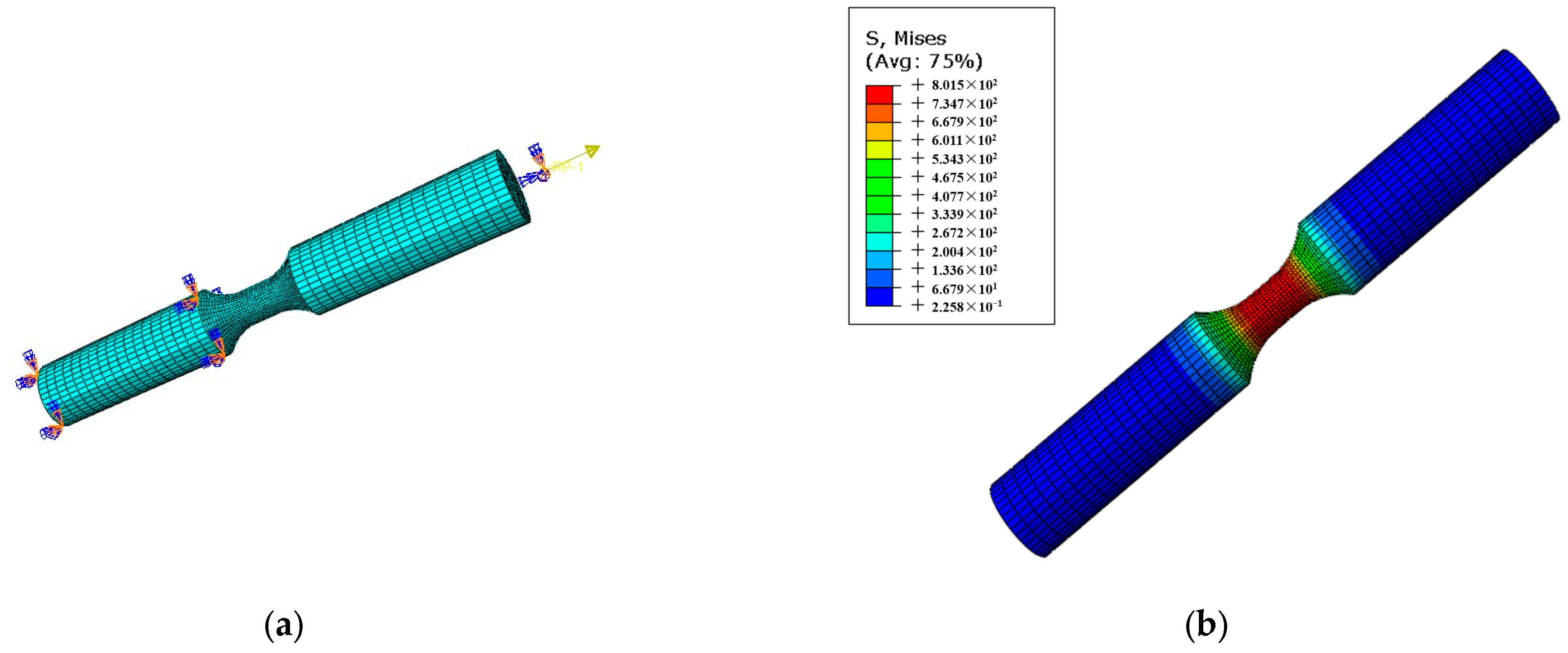
4.2. Numerical Implementation

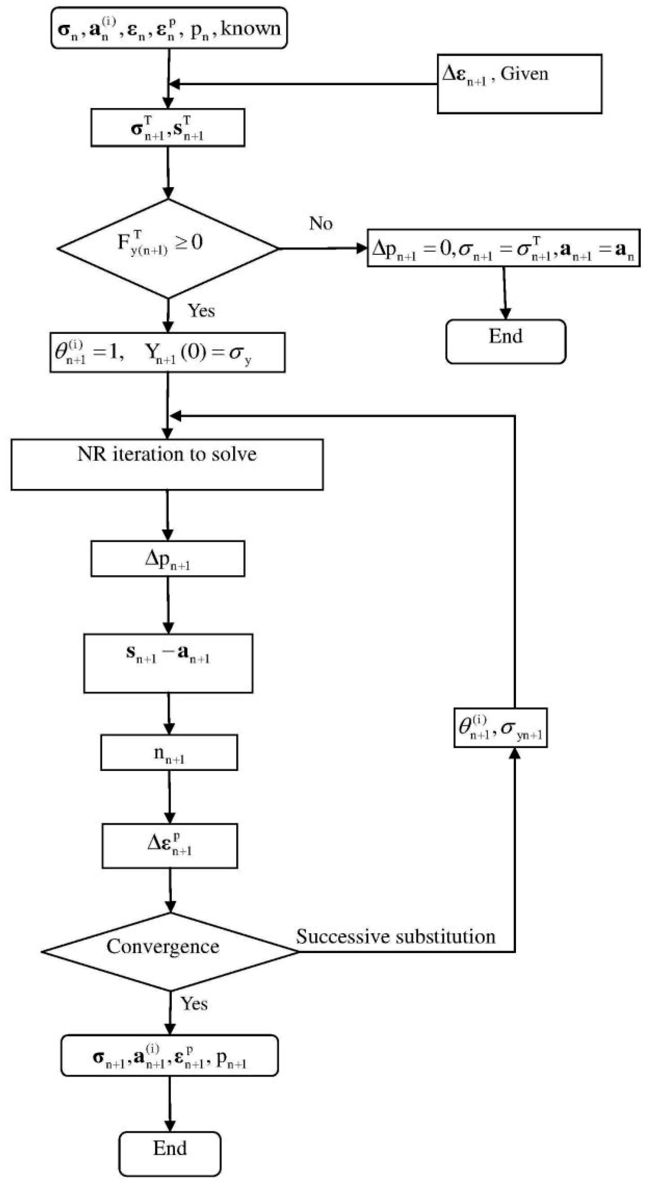
4.2.1. Implicit Stress Integration Method

Using the elastic prediction, the total strain at the n + 1 moment could be discretized as the following:
ε n + 1 = ε n + 1 e + ε n + 1 p
From Hooke’s law, the relation between stress and elastic strain was obtained, where the elastic strain follows Hooke’s law, representing small-deformation behavior:
σ n + 1 = C : ε n + 1 e
Plastic strain increment and cumulative plastic strain increment relational equation:
Δ ε n + 1 p = 3 2 Δ p n + 1 n n + 1
where the direction nn+1 normal to the yield surface was expressed as the following:
n n + 1 = 3 2 s n + 1 α n + 1 σ y
Substituting (16) into (15) yields:
Δ ε n + 1 p = 3 2 Δ p n + 1 s n + 1 α n + 1 σ y
Consistency condition:
F n + 1 = 3 2 ( s n + 1 α n + 1 ) : ( s n + 1 α n + 1 ) σ y n + 1 = 0
Based on the consistency yield condition, it could be derived from Equations (7) and (18):
n n + 1 : n n + 1 = 1
Discrete to Equation (12) was obtained:
Δ R n + 1 = b Q R n + 1 Δ p n + 1
Following the idea of the radial return method and assuming that the total strain increment Δ ε n + 1 was all elastic deformation, the trial stress σ n + 1 T at moment n + 1 could be derived from Hooke’s law:
σ n + 1 T = C : ε n + 1 T
Trial strain:
ε n + 1 T = ε n + 1 ε n p
Substituting (22) into (21) yields:
σ n + 1 T = C : ε n + 1 ε n + 1 p + Δ ε n + 1 p = σ n + 1 + C : Δ ε n + 1 p
From the assumption of isotropy and plastic incompressibility we obtained the following:
C : Δ ε n + 1 p = 2 G Δ ε n + 1 p
where G was the shear modulus of elasticity:
G = E 2 1 + v
combining (23) and (24) gave the following result:
s n + 1 = s n + 1 T 2 G Δ ε n + 1 p
The discretisation of the AF-OWII follower strengthening law yields.
α n + 1 = i = 1 M r i b n + 1 i
b n + 1 i = b n i + 2 3 γ i Δ ε n + 1 p γ i Δ p n + 1 i b n + 1 i
Δ p n + 1 i = μ i + b n + 1 i ¯ m i Δ ε n + 1 p : b n + 1 i μ i Δ p n + 1
θ n + 1 i = 1 1 + γ i Δ p n + 1 i
Substituting (30) into (28) gave the following:
b n + 1 i = θ n + 1 i b n i + 2 3 γ i Δ ε n + 1 p
Δ p n + 1 i = p n + 1 i p n i
From Equations (26) and (27):
s n + 1 α n + 1 = s n + 1 T 2 G Δ ε n + 1 p i = 1 M r i b n + 1 i
Kobayashi and Ohno [45] showed that in Equation (30) is more suitable for the radial backward mapping method than in Equation (32). The process of radial return method was shown schematically in Figure 9:
From Equation (31), it could be seen that the change of b i from b n i to b n + 1 i was caused by Δ ε n + 1 p . Assumed that the predicted value of b n + 1 i was b n + 1 ( i ) * , and
b n + 1 i * = b n + 1 i + 2 3 γ i Δ ε n + 1 p
If b n + 1 i * lay in or on the critical plane, b n + 1 i * was accepted as b n + 1 i . Otherwise, b n + 1 i * was mirrored along the critical plane and mapped to the critical plane to obtain b n + 1 i :
b n + 1 i = θ n + 1 i b n + 1 i *
Combining (33), (34), and (35) yields the following:
s n + 1 α n + 1 = s n + 1 T 2 G Δ ε n + 1 p i = 1 M θ n + 1 i r i b n i + 2 3 γ i Δ ε n + 1 p
Substituting (16) into (36) yields the following:
s n + 1 α n + 1 = σ y s n + 1 T i = 1 M θ n + 1 i r i b n i σ y + Δ p n + 1 3 G + i = 1 M γ i r i θ n + 1 i
From the consistent yield condition (18):
Δ p n + 1 = 3 2 s n + 1 T i = 1 M θ n + 1 i r i b n i : s n + 1 T i = 1 M θ n + 1 i r i b n i σ y 3 G + i = 1 M γ i r i θ n + 1 i
Also, from Equations (29) and (30):
θ n + 1 i = 1 1 + γ i μ i + b n + 1 i ¯ m i Δ ε n + 1 p : b n + 1 i μ i Δ p n + 1
The specific flow algorithm for this model was shown in Figure 10.

4.2.2. Consistent Tangent Stiffness Matrix

The finite element implementation of the rate-independent AF-OW II model required the consistent tangent stiffness matrices, which could accelerate convergence. The specific derivation process was described below:
Differentiating the aforementioned intrinsic model yields:
Δ σ n + 1 = C : Δ ε n + 1 Δ ε n + 1 p
Δ ε n + 1 p = Δ p n + 1 n n + 1
d n n + 1 = 3 2 d Δ s n + 1 d Δ α n + 1 σ y n n + 1 σ y d σ y d p n + 1 d Δ p n + 1
n n + 1 T : n n + 1 = 3 2
Differentiating Equation (33) yields the following:
d Δ σ n + 1 = C : d Δ ε n + 1 d Δ ε n + 1 p
Substituting (22) into (37), the differentiation of the bias stress increment was obtained by using the fourth-order bias operation tensor I d expressed as the following:
d Δ s n + 1 = 2 G I d : d Δ ε n + 1 M 1 d Δ ε n + 1 p
Differentiating Equation (34) yields the following:
d Δ ε n + 1 p = M 2 d Δ p n + 1 n n + 1 + Δ p n + 1 d n n + 1
Differentiating Equation (36) yields the following:
n n + 1 T : d n n + 1 = 0
n n + 1 T : d Δ ε n + 1 p = n n + 1 T : M 2 d Δ p n + 1 n n + 1 + Δ p n + 1 d n n + 1
Substituting (40) into (41) gave the following:
d Δ p n + 1 = 2 3 n n + 1 T : d Δ ε n + 1 p
Substituting (35) and (42) into (39) gave the following:
2 σ y 3 Δ p n + 1 d Δ ε n + 1 p = 4 9 n n + 1 : n n + 1 T σ y Δ p n + 1 d σ y d p n + 1 d ε n + 1 p + M 2 d Δ s n + 1 d Δ α n + 1
The differentiation of the backstress increment d Δ α could usually be expressed in terms of the fourth-order constitutive parameters H n + 1 i .
d Δ α n + 1 = i = 1 M H n + 1 i : d Δ ε n + 1 p
Substituting Equations (38) and (44) into Equation (43) yields the following:
L n + 1 : d Δ ε n + 1 p = 2 G I d : d Δ ε n + 1
L n + 1 = 2 σ y 3 Δ p n + 1 + 2 G : I + M 2 i = 1 M H n + 1 i 4 9 σ y Δ p n + 1 d σ y d p n + 1 n n + 1 : n n + 1 T
where I was the unit matrix.
H n + 1 i = 2 3 r i γ i M 2 γ i α n + 1 i n n + 1 T μ i + α n + 1 i ¯ r i m i n n + 1 T : α n + 1 i r i μ i 1 + μ i Δ p n + 1 + α n + 1 i ¯ r i m i Δ ε n + 1 p : α n + 1 i α n + 1 i ¯ μ i Δ p n + 1
Substituting Equation (45) into Equation (37) yields the consistent elastic-plastic tangent stiffness matrix:
d Δ σ n + 1 d Δ ε n + 1 = C 4 G 2 L n + 1 1 : I d

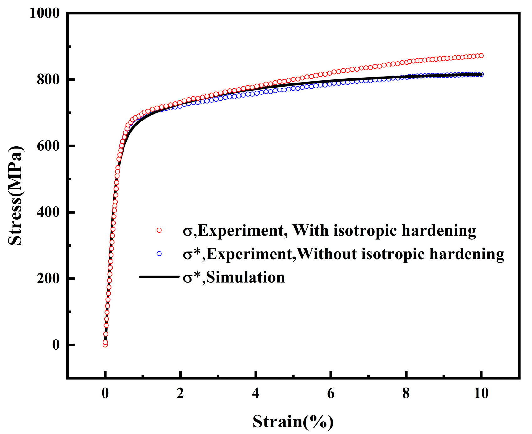
4.3. Determination of Model Parameters

For the purpose of employing this model to depict the ratcheting deformation behavior of SAF2507 stainless steel, it is requisite to initially ascertain the values of the material parameters.

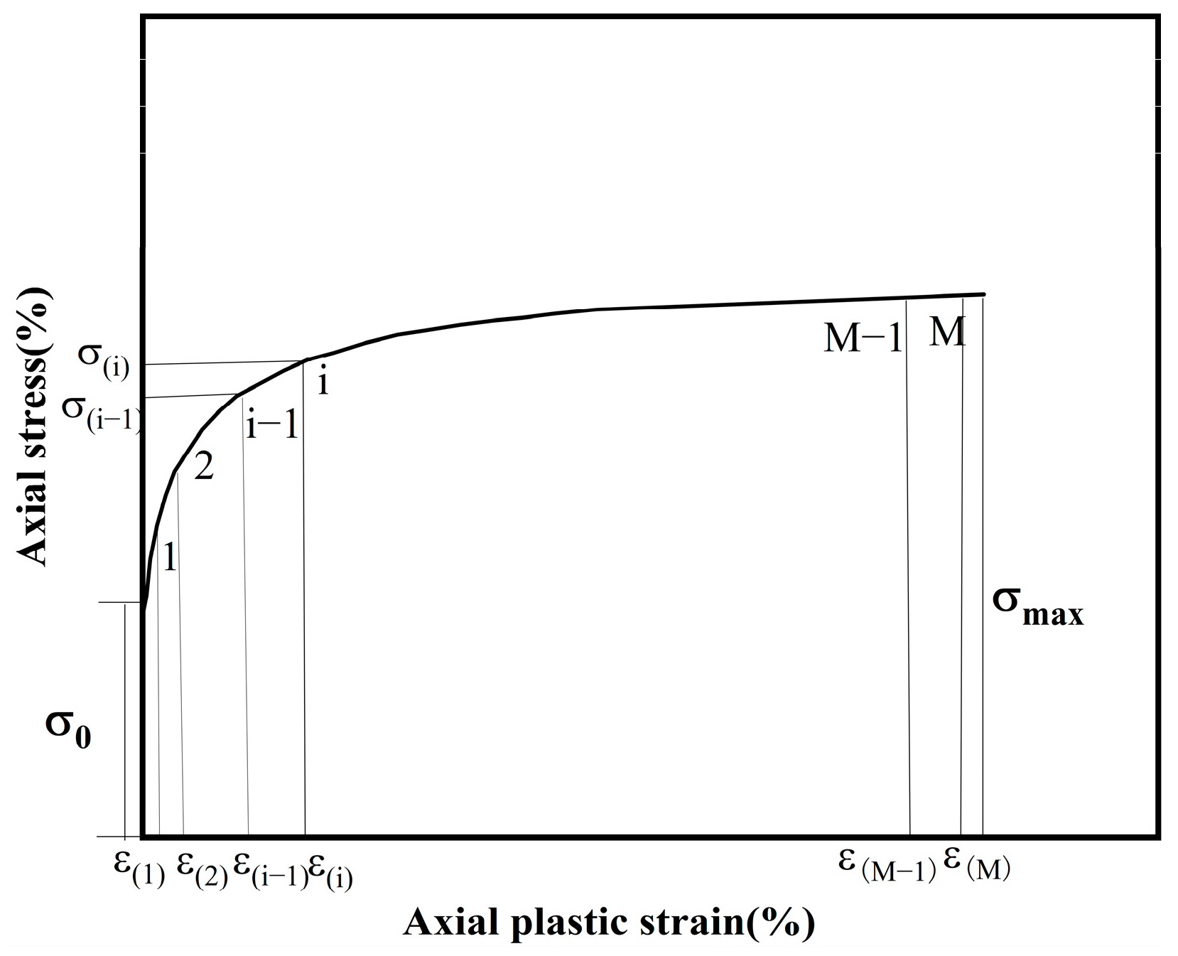
4.3.1. Determination of Parameters Q and b

It could be concluded that SAF2507 was a cyclic hardening material, which was regarded as isotropically hardened in the study of this paper.
σ max = C + Q 1 exp ( b p ) ; p p max 1 stc
where C was a constant and p max 1 stc was the maximum plastic strain in the first loop (i.e., the initial uniaxial stretching section). Using the above equation, Q and b could be obtained by least-squares fitting of the curves of peak stress and accumulated plastic strain (shown in Figure 11).

4.3.2. Determination of Parameters γ and r

To determine parameters γ and r , the first step was to obtain the uniaxial tensile stress–strain curve of SAF2507 stainless steel. Figure 12 shows the stress–strain curve of the material at different rates. From the figure, it can be seen that the yield stress of SAF2507 stainless steel remained almost constant under three different loading rates, and the stress value corresponding to the same strain under different strain rates changed very little.
Parameters γ i and r i could be determined from a uniaxial tensile curve, and the effect of strain hardening needed to be subtracted when fitting the uniaxial tensile curve. As shown in Figure 13, the monotonic stress–strain curve was divided into several segments so that each segment was linearly connected to be able to simulate the nonlinear relationship of the tensile curve, and the corresponding parameters γ i and r i , could be derived from the following equations:
γ i = 1 ε p i , r i = σ i σ i 1 ε p i ε p i 1 σ i + 1 σ i ε p i + 1 ε p i ε p i i 1
i = 1 M r i + σ 0 = σ max
The parameters obtained by the above method were used to simulate the uniaxial tensile curve of SAF2507 and the results are shown in Figure 14.

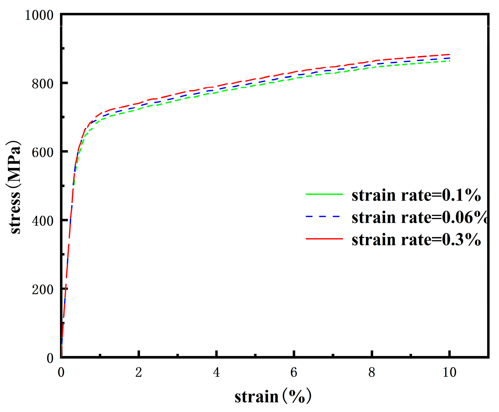
4.3.3. Determination of Parameters μ and m

The parameters μ and m were closely related to the ratcheting behavior of the material. These two parameters only affected the ratcheting behavior of the material. These two parameters were derived through the trial-and-error method based on the experimental data of uniaxial ratchetings. The relevant parameters of the model used in this study are presented in Table 4.

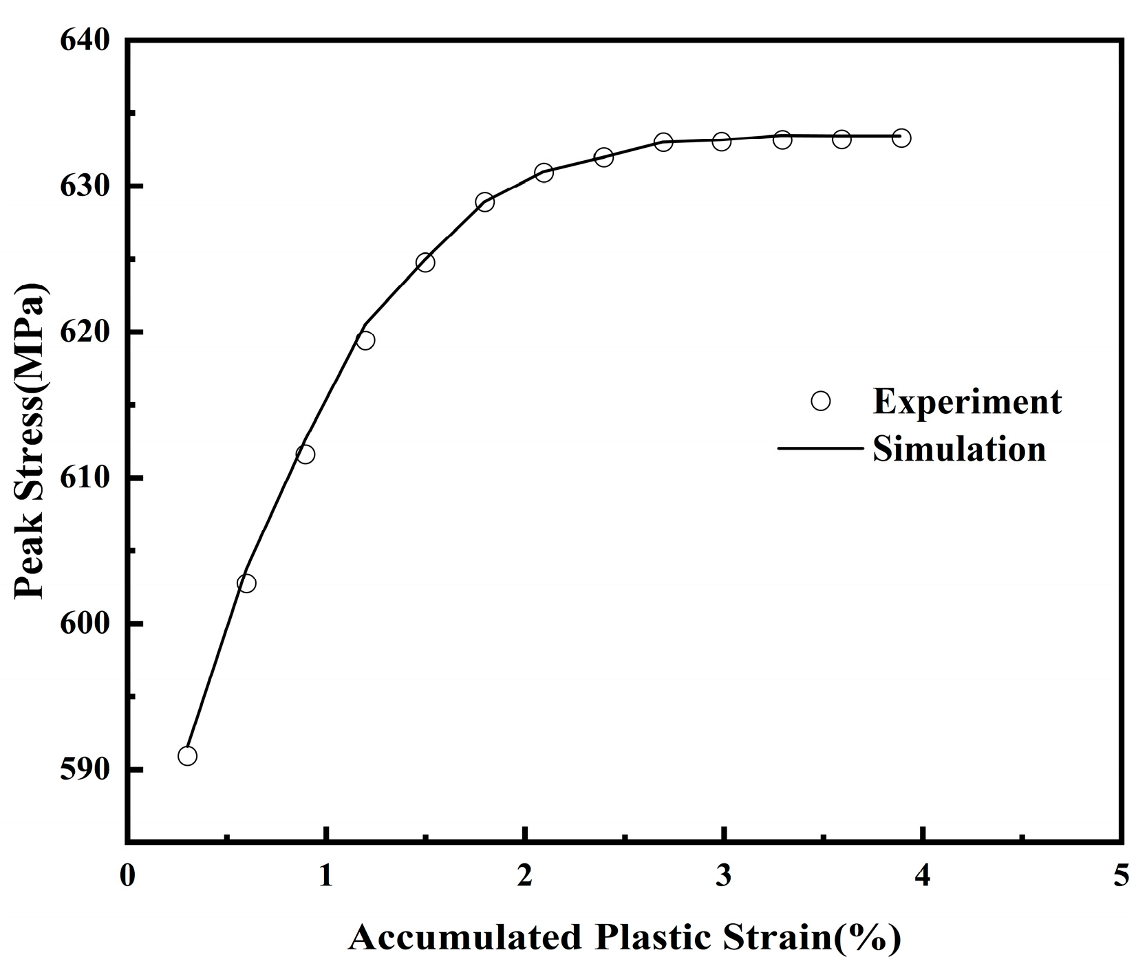
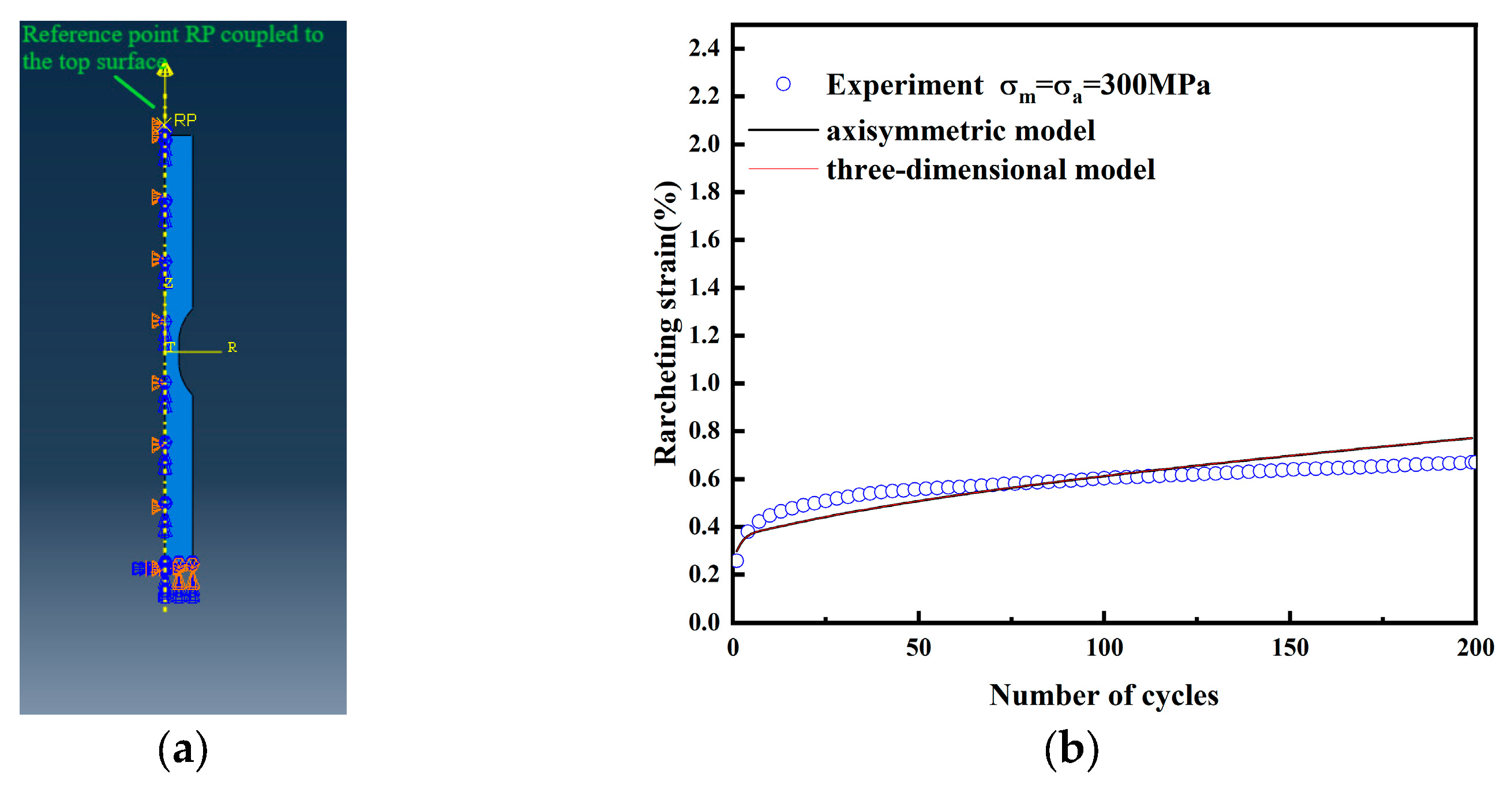
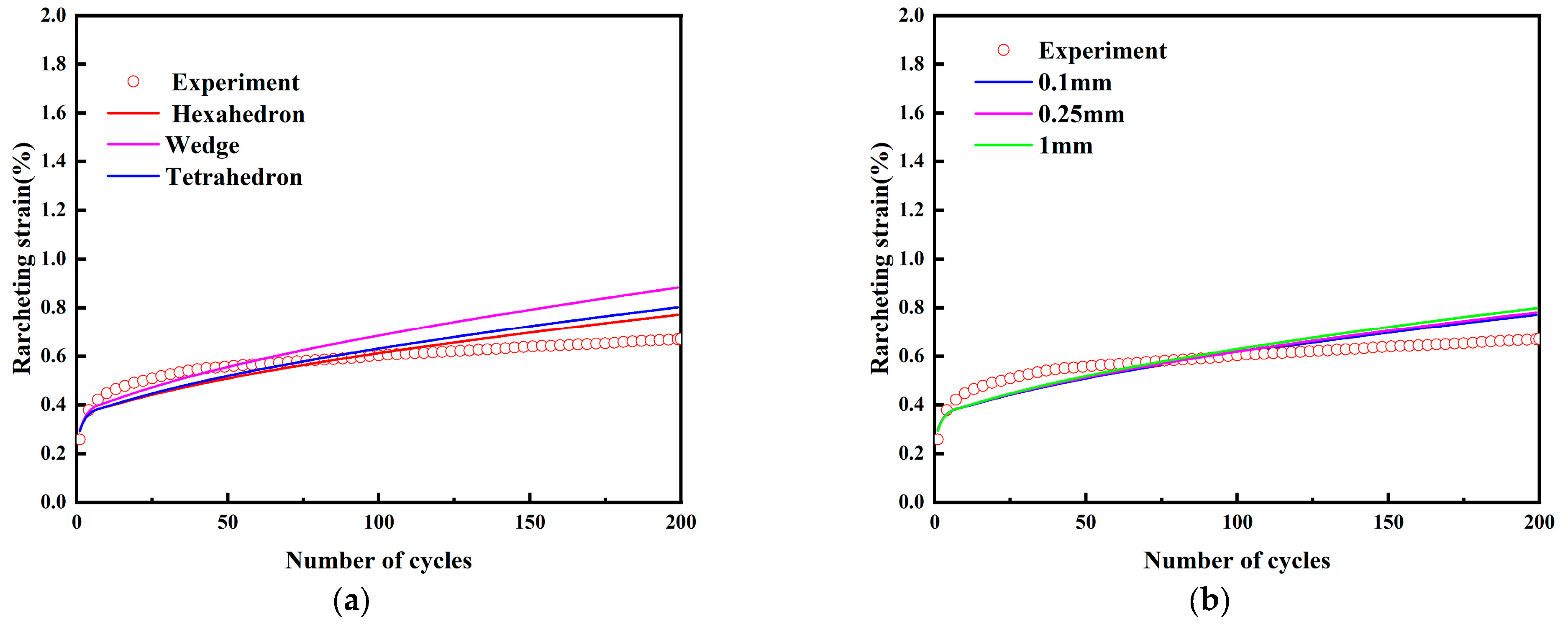
4.4. Comparison of Simulation and Experimental Results

The three-dimensional geometry of the sample was built with Abaqus-CAE sketcher tool. The geometry of the sample consisted of a cylindrical solid with a reduced cross-section length in the middle, as given in Figure 15. There were different types of finite elements, and the element size also affected the precision and computing performance. It was important to balance both element type and element size in order to obtain results with a fairly small error and in a relatively short time. Within the framework of the finite element model, one end of the model was completely fixed (U1 = U2 = U3 = UR1 = UR2 = UR3 = 0). A reference point RP-1 was established at the center of the top surface of the model and coupled to the top surface, and the cyclic axial load was applied to the reference point RP-1. As depicted in Figure 15b, the Mises stress that emerged in the middle section of the specimen was presented. Consequently, the ratcheting strain located in the middle section of the specimen was singled out for the purpose of conducting a comparative analysis.
In this paper, an axisymmetric 2D model was also used to investigate the effect of model space on accuracy. As shown in Figure 16a, symmetric constraints were applied along the left edge of the 2D model, i.e., U1 = UR2 = UR3 = 0. At the center of the top surface, a reference point RP-1 was created and coupled to the top surface for applying axial loads, and these constraints took into account the possible displacement limitations in that direction. As shown in Figure 16b, simulations of the uniaxial ratchet effect were carried out using both the 2D axisymmetric model and the 3D model. It was found that the ratchet strains predicted by both models were the same and the model space had no effect on the ratchet effect simulation results.
In order to demonstrate that the numerical results were not affected by spurious mesh correlations, Figure 17 showed the comparison of the ratcheting strains of models using different finite element types under loading conditions with an average stress of 300 MPa and a stress amplitude of 300 MPa. Figure 17a showed the simulation results of the finite element models using different grid cell shapes (hexahedral, tetrahedral, and wedge), and the gauge length in all simulation analyses was 0.25 mm. The total number of cells generated using hexahedral finite elements, tetrahedral finite elements, and wedge cell shapes was 11,780, 39,624, and 20,064, respectively. The results showed that the use of hexahedral finite elements was more suitable for further analysis. As shown in Figure 17b, the gauge lengths in this finite element model were simulated using three different sizes (0.1 mm, 0.25 mm, and 1 mm). It could be seen from the figure that the simulation results using the three sizes of hexahedral cell meshes were basically the same, and the use of a 0.25 mm gauge length was appropriate.
Figure 18a,b compared the experimental and predicted results of the stress–strain hysteresis loops for the first 200 cycles under a stress amplitude of 300 MPa and a mean stress of 500 MPa, respectively. It could be seen that the shapes of the simulated hysteresis loop were in agreement with the experimental results. Figure 19 presents the evolution of the ratcheting strain. It can be observed that the predicted results of uniaxial ratcheting strain with ABAQUS were consistent with the experimental data. The relative errors between the simulated and experimental ratcheting strains during stress loading are given in Table 5.

5. Conclusions

We performed a series of uniaxial ratcheting experiments on super duplex SAF2507 stainless steel and evaluated the effects of stress amplitude, mean stress, and pre-strain on ratcheting strain. In addition, a three-dimensional ratcheting strain boundary diagram containing stress amplitude, mean stress, and ratcheting strain rate was created. Numerical analysis was performed in Abaqus by incorporating an isotropically hardened AF-OW II model. The following conclusions were drawn:
(1)
The ratcheting strain increased with increasing mean stress and stress amplitude for the same stress conditions. In addition, the ratcheting strain decreased as the pre- strain level increased.
(2)
With the help of experimental results for certain groups of mean stress and stress amplitude conditions, three-dimensional ratcheting boundary surface maps were drawn. With the experimental results of a finite group, multiple stress combinations and their corresponding ratcheting strain rates were obtained. Thus, experimental cost and time were saved.
(3)
Through a comprehensive comparison of the simulated and experimental values of the ratcheting strain of SAF2507 stainless steel under diverse loading scenarios, the proposed model demonstrated its ability to reasonably predict the ratcheting strain of SAF2507 stainless steel at room temperature.
(4)
Pre-strain showed an inhibitory effect on the ratcheting effect of SAF2507 stainless steel, which could be further investigated.

Author Contributions

Conceptualization, H.L. and X.C. (Xiaohui Chen); investigation, H.L.; methodology, X.Z.; project administration, X.C. (Xiaodong Cui); validation, H.L.; writing—original draft, H.L. and X.Z.; writing—review and editing, H.L. and X.C. (Xiaohui Chen). All authors have read and agreed to the published version of the manuscript.

Funding

This research received no external funding.

Institutional Review Board Statement

Not applicable.

Data Availability Statement

The original contributions presented in the study are included in the article. Further inquiries can be directed to the corresponding authors.

Conflicts of Interest

The authors declare no conflicts of interest.

References

  1. Han, K.; Chen, Z.F.; Wang, W.; Shi, L.; Lu, K.Q. A short review of ratcheting effect in pressurized piping. Int. J. Press. Vessel. Pip. 2023, 205, 105009. [Google Scholar] [CrossRef]
  2. Yao, Z.H.; Li, C.Y.; Hao, J.; Zhang, H.Z.; Lv, G.C.; Da, W.B. Investigation of ratcheting fatigue behavior and failure mechanism of 1Cr18Ni10Ti pressure pipe under different force amplitudes and internal fluid pressure. Eng. Fail. Anal. 2024, 162, 108386. [Google Scholar] [CrossRef]
  3. Zhou, W.T.; Zhou, G.Y.; Xiong, X.Y.; Xuan, F.Z.; Tu, S.T. Uniaxial ratcheting behavior and microstructure evolution of 316H stainless steel under the random cyclic loads. Mater. Charact. 2023, 203, 113165. [Google Scholar] [CrossRef]
  4. Chen, X.; Jiao, R.; Kim, K.S. Simulation of ratcheting strain to a high number of cycles under biaxial loading. Int. J. Solids Struct. 2003, 40, 7449–7461. [Google Scholar] [CrossRef]
  5. Chen, X.; Jiao, R.; Kim, K.S. On the Ohno–Wang kinematic hardening rules for multiaxial ratcheting modeling of medium carbon steel. Int. J. Plast. 2005, 21, 161–184. [Google Scholar] [CrossRef]
  6. Chen, G.; Chen, X.; Niu, C.D. Uniaxial ratcheting behavior of 63Sn37Pb solder with loading histories and stress rates. Mater. Sci. Eng. 2006, 421, 238–244. [Google Scholar] [CrossRef]
  7. Kang, G.Z.; Gao, Q.; Yang, X.J. A visco–plastic constitutive model incorporated with cyclic hardening for uniaxial/multiaxial ratcheting of SS304 stainless steel at room temperature. Mech. Mater. 2002, 34, 521–531. [Google Scholar] [CrossRef]
  8. Kang, G.Z.; Liu, Y.J. Uniaxial ratchetting and low-cycle fatigue failure of the steel with cyclic stabilizing or softening feature. Mater. Sci. Eng. A. 2008, 472, 258–268. [Google Scholar] [CrossRef]
  9. Chen, X.H. A Study on the Ratcheting and Shakedown Behavior of Pressurized Piping Components under Cyclic Loading. Ph.D. Thesis, Tianjin University, Tianjin, China, 2013. [Google Scholar]
  10. Zhang, Q. Ratcheting Analysis of Primary Auxiliary Piping Loop of Nuclear Power Plants. Master’s Thesis, Tianjin University, Tianjin, China, 2010. [Google Scholar]
  11. Zhu, J.B. Bending Ratcheting Tests of Pressurized Straight Stainless Steel Pipes. Master’s Thesis, Tianjin University, Tianjin, China, 2011. [Google Scholar]
  12. Wang, Y. A Study on the Uniaxial Ratcheting-Fatigue Behavior of Austenitic Stainless Steel for Primary Coolant Circuit Auxiliary Pipes of Pressure Water Reactor. Master’s Thesis, Tianjin University, Tianjin, China, 2013. [Google Scholar]
  13. Kang, G.Z. Ratchetting: Recent progresses in phenomenon observation, constitutive modeling and application. Int. J. Fatigue 2008, 30, 1448–1472. [Google Scholar] [CrossRef]
  14. Mroz, Z. On the description of anisotropic work hardening. J. Mech. Phys. Solid. 1967, 15, 163–175. [Google Scholar] [CrossRef]
  15. Dafalias, Y.F.; Popov, E.P. Plastic internal variables formalism of cyclic plasticity. ASMEJ. Appl. Mech. 1976, 43, 645–651. [Google Scholar] [CrossRef]
  16. Chaboche, J.L. A review of some plasticity and viscoplasticity constitutive theories. Int. J. Plast. 2008, 24, 1642–1693. [Google Scholar] [CrossRef]
  17. Chaboche, J.L.; Nouailhas, D. Constitutive Modeling of Ratchetting Effects—Part I: Experimental Facts and Properties of the Classical Models. J. Eng. Mater. Technol. 1989, 111, 384–392. [Google Scholar] [CrossRef]
  18. Chaboche, J.L.; Nouailhas, D. Constitutive Modeling of Ratchetting Effects—Part II: Possibilities of Some Additional Kinematic Rules. J. Eng. Mater. Technol. 1989, 111, 409–416. [Google Scholar] [CrossRef]
  19. Chaboche, J.L. On Some Modifications of Kinematic Hardening to Improve the Description of Ratchetting Effects. Int. J. Plast. 1991, 7, 661–678. [Google Scholar] [CrossRef]
  20. Ohno, N.; Wang, J.D. Kinematic Hardening Rules with Critical State of Dynamic Recovery, Part I: Formulation and Basic Features for Ratchetting Behavior. Int. J. Plast. 1993, 9, 375–390. [Google Scholar] [CrossRef]
  21. Ohno, N.; Wang, J.D. Kinematic Hardening Rules with Critical State of Dynamic Recovery, Part II: Application to Experiments of Ratchetting Behavior. Int. J. Plas. 1993, 9, 391–403. [Google Scholar] [CrossRef]
  22. Yaguchi, M.; Takahashi, Y. Ratchetting of Viscoplastic Material with Cyclic Softening, Part 2: Application of Constitutive Models. Int. J. Plast. 2005, 21, 835–860. [Google Scholar] [CrossRef]
  23. Bari, S.; Hassan, T. An advancement in cyclic plasticity modeling for multiaxial ratcheting simulation. Int. J. Plast. 2002, 18, 873–894. [Google Scholar] [CrossRef]
  24. Delobelle, P.; Robinet, P.; Bocher, L. Experimental study and phenomenological modelization of ratchet under uniaxial and biaxial loading on an austenitic stainless steel. Int. J. Plast. 1995, 11, 295–330. [Google Scholar] [CrossRef]
  25. Ahmadzadeh, G.R.; Varvani-Farahani, A. Ratcheting Assessment of Steel Alloys under Step-Loading Conditions. Mater. Des. 2013, 51, 231–241. [Google Scholar] [CrossRef]
  26. Ahmadzadeh, G.R.; Varvani-Farahani, A. A Kinematic Hardening Rule to Investigate the Impact of Loading Path and Direction on Ratcheting Response of Steel Alloys. Mech. Mater. 2016, 101, 40–49. [Google Scholar] [CrossRef]
  27. Okorokov, V.; Gorash, Y.; Mackenzie, D.; Rijswick, R.V. New Formulation of Nonlinear Kinematic Hardening Model, Part II: Cyclic Hardening/Softening and Ratcheting. Int. J. Plast. 2019, 122, 244–267. [Google Scholar] [CrossRef]
  28. Chen, X.H.; Lang, L.; Zhu, L.; Zhao, X.; Liu, H.R. Ratcheting assessment of pressurized elbow pipes using the visco-plastic Chen-Jiao-Kim hardening rule frameworks. Int. J. Plast. 2023, 205, 104995. [Google Scholar] [CrossRef]
  29. Abadie, C.N.; Houlsby, G.T.; Byrne, B.W. A Method for Calibration of the Hyperplastic Accelerated Ratcheting Model (HARM). Comput. Geotech. 2019, 112, 370–385. [Google Scholar] [CrossRef]
  30. Chen, Y.N.; Chen, X.H.; Gao, B.J.; Chen, X.; Zhang, K.; Yu, C.L. A Cyclic Plasticity Model with Martensite Transformation for S30408 and Its Finite Element Implementation. Appl. Sci. 2020, 10, 6002. [Google Scholar] [CrossRef]
  31. Jiao, R.; Kyriakides, S. Ratcheting and wrinkling of tubes due to axial cycling under internal pressure: Part II analysis. Int. J. Solids Struct. 2011, 48, 2827–2836. [Google Scholar] [CrossRef]
  32. Chen, X.H.; Tian, Y.S.; Liu, S.J.; Lang, L. Ratcheting evaluation of pressurized straight pipe using Ahmadzadeh-Varvani hardening rule. Thin-Walled Struct. 2022, 179, 109684. [Google Scholar] [CrossRef]
  33. Abdel-Karim, M.; Ohno, N. Kinematic hardening model suitable for ratcheting with steady-state. Int. J. Plast. 2000, 16, 225–240. [Google Scholar] [CrossRef]
  34. Tian, Y.S.; Chen, X.H.; Chen, T.X.; Zhu, L. Ratcheting response and boundary of austenitic stainless steel in a pressurized straight pipe subjected to in-plane bending cycles. Int. J. Press. Vessel. Pip. 2023, 203, 104855. [Google Scholar] [CrossRef]
  35. Chen, G.; Zhao, X. Constitutive modelling on the whole-life uniaxial ratcheting behavior of sintered nano-scale silver paste at room and high temperatures. Microelectron. Reliab. 2018, 80, 47–54. [Google Scholar] [CrossRef]
  36. Liu, X.Y.; Dong, Y.W.; Xiao, X. Study on constitutive model of cyclic ratcheting considering memory recovery of plastic strain. Chin. J. Sol. Mech. 2018, 39, 429–437. [Google Scholar]
  37. Chen, X.H.; Liu, S.J.; Tian, Y.S.; Zhu, L.; Lang, L. Unified viscoplasticity model for type 316 stainless steel subjected to isothermal and anisothermal-mechanical loading. Int. J. Press. Vessel. Pip. 2023, 97, 104855. [Google Scholar] [CrossRef]
  38. Kolasangiani, K.; Varvani-Farahani, A. Local ratcheting assessment of steel samples undergoing various step and block loading conditions. Theor. Appl. Fract. Mech. 2020, 107, 102533. [Google Scholar] [CrossRef]
  39. ISO 12106:2003(E); Metallic Materials-Fatigue Testing-Axial-Strain-Controlled Method. ISO: Geneva, Switzerland, 2003.
  40. Chen, X.H.; Chen, X.; Chen, H.F. Influence of stress level on uniaxial ratcheting effect and ratcheting strain rate in austenitic stainless steel Z2CND18.12N. Steel Compos. Struct. 2018, 27, 89–94. [Google Scholar] [CrossRef]
  41. Li, C.; Chen, G.; Chen, X.; Zhang, W.H. Ratcheting strain and simulation of 16MnR steel under uniaxial cyclic loading. Comput. Mater. Sci. 2012, 57, 43–47. [Google Scholar] [CrossRef]
  42. Wang, Y.D.; Chen, G.; Chen, X. Effects of pre-strain on uniaxial ratcheting and fatigue failure of Z2CN18. 10 austenitic stainless steel. Int. J. Fatigue 2013, 52, 106–113. [Google Scholar] [CrossRef]
  43. Tripathy, S. Effect of Pre-Strain and Pre-Corrosion on Ratcheting Behavior of ASTM A668 Class D steel. Master’s Thesis, National Institute of Technology Rourkela, Odisha, India, 2016. [Google Scholar]
  44. Zhang, J. Constitutive Description for Non-Proportionally Ratcheting of Cyclically Hardening Material and Its Finite Element Implementation at High Temperatures. Ph.D. Thesis, Southwest Jiaotong University, Chengdu, China, 2006. [Google Scholar]
  45. Kobayashi, M.; Ohno, N. Implementation of cyclic plasticity models based on a general form of kinematic hardening. Int. J. Numer. Meth. Engng. 2002, 53, 2217–2238. [Google Scholar] [CrossRef]
Figure 1. Geometry of the specimen used for tests.
Applsci 15 01424 g001
Figure 2. Set up of the equipment apparatus.
Applsci 15 01424 g002
Figure 3. Test U3: (a) Stress control diagram, (b) stress–strain relationship, (c) ratcheting strain, (d) ratcheting strain rate.
Applsci 15 01424 g003
Figure 4. Uniaxial ratcheting tests with the constant amplitude of 300 MPa and different mean stresses (a) stress–strain hysteresis loop and (b) ratcheting strain evolution.
Applsci 15 01424 g004
Figure 5. Uniaxial ratcheting tests with the constant mean stress of 400 MPa and different stress amplitudes: (a) stress–strain hysteresis loop, (b) ratcheting strain evolution.
Applsci 15 01424 g005
Figure 6. Uniaxial ratcheting tests with constant stress control and different pre-strains.
Applsci 15 01424 g006
Figure 7. (a) Ratcheting strain rate vs. stress amplitude; (b) ratcheting strain rate vs. mean stress.
Applsci 15 01424 g007
Figure 8. Three-dimensional ratcheting response surface.
Applsci 15 01424 g008
Figure 9. Sketch of radial return mapping.
Applsci 15 01424 g009
Figure 10. Flow diagram of radial return algorithm.
Applsci 15 01424 g010
Figure 11. Sketch map of simulating the parameter Q and b.
Applsci 15 01424 g011
Figure 12. Uniaxial tensile curve.
Applsci 15 01424 g012
Figure 13. Determination of parameters γ i and r i .
Applsci 15 01424 g013
Figure 14. Uniaxial stretch curve.
Applsci 15 01424 g014
Figure 15. (a) Rod specimen model; (b) stress contour.
Applsci 15 01424 g015
Figure 16. (a) Axisymmetric model; (b) comparison of the predictions of the two models with the experimental.
Applsci 15 01424 g016
Figure 17. Comparison between finite element types: (a) different grid cell shapes, (b) different grid sizes.
Applsci 15 01424 g017
Figure 18. Stress–strain hysteresis loop: (a) experiments; (b) simulations.
Applsci 15 01424 g018
Figure 19. Prediction of ratcheting strain: (a) different mean stresses; (b) different stresses amplitude.
Applsci 15 01424 g019
Table 1. The chemical compositions of SAF2507 stainless steel.
CompositionCMoMnCrPSiSNNiFe
Content/%0.0341.2525.010.0380.820.020.32761.5
Table 2. Loading conditions of uniaxial ratcheting test.
No.σm/MPaσα/MPaNcεh/%
Y13003002000
Y24003002000
Y35003002000
Y44003502000
Y54004002000
Y64004002000.4
Y74004002000.8
Y84004002001.2
Table 3. Slope, intercept, and stress values at zero ratcheting strain.
MaterialFigure
No.
Slope
m
Intercept
c
Zero Ratcheting Strain Rate
Mean StressStress Amplitudes
SAF2507Figure 7a0.0467−12.725400272.48
Figure 7b0.024−6.8283.33300
Table 4. Material parameters.
E = 193 GPa,ν = 0.3,σ0 = 100 MPa
r 1 6 10, 65, 60, 39, 73, 162     γ 1 6 4915, 2451, 1232, 612.5, 406.5, 32.125
μ = 0.6, Q = 59 MPa, b = 2.3, m = 2.5
Table 5. Relative errors of ratcheting strain.
No.U1U2U3U4U5
Max/%15.0918.017.516.5510.68
Min/%0.080.13.044.550.11
Disclaimer/Publisher’s Note: The statements, opinions and data contained in all publications are solely those of the individual author(s) and contributor(s) and not of MDPI and/or the editor(s). MDPI and/or the editor(s) disclaim responsibility for any injury to people or property resulting from any ideas, methods, instructions or products referred to in the content.

