1. Introduction
Continuous Miner Technology has restored the faith of the Indian mining industry in underground coal mining methods. This technology has proved to be successful with improved efficiency and safety in the difficult and complex geo-mining conditions of Indian underground coal mines. A number of coal mines have already adopted this technology since its introduction in 2003 in the Anjan Hill mine of the Chirimiri Area of South Eastern Coalfields Limited (a subsidiary of Coal India Limited). In this line, the Tawa-I mine in the Pathakhera Area of Western Coalfields Limited (also a subsidiary of Coal India Limited) is planning to introduce this technology. Based on the project report and sheme prepared by CMPDIL, it has been proposed by the mine management of the Tawa-I mine to introduce Continuous Miner (CM) Technology in the Bagdona Coal Seam of the mine. The BCS panels of the Tawa-I mine are being developed by the conventional drilling and blasting method with a 3.8 m gallery width up to full seam thickness (average thickness = 1.80 m).
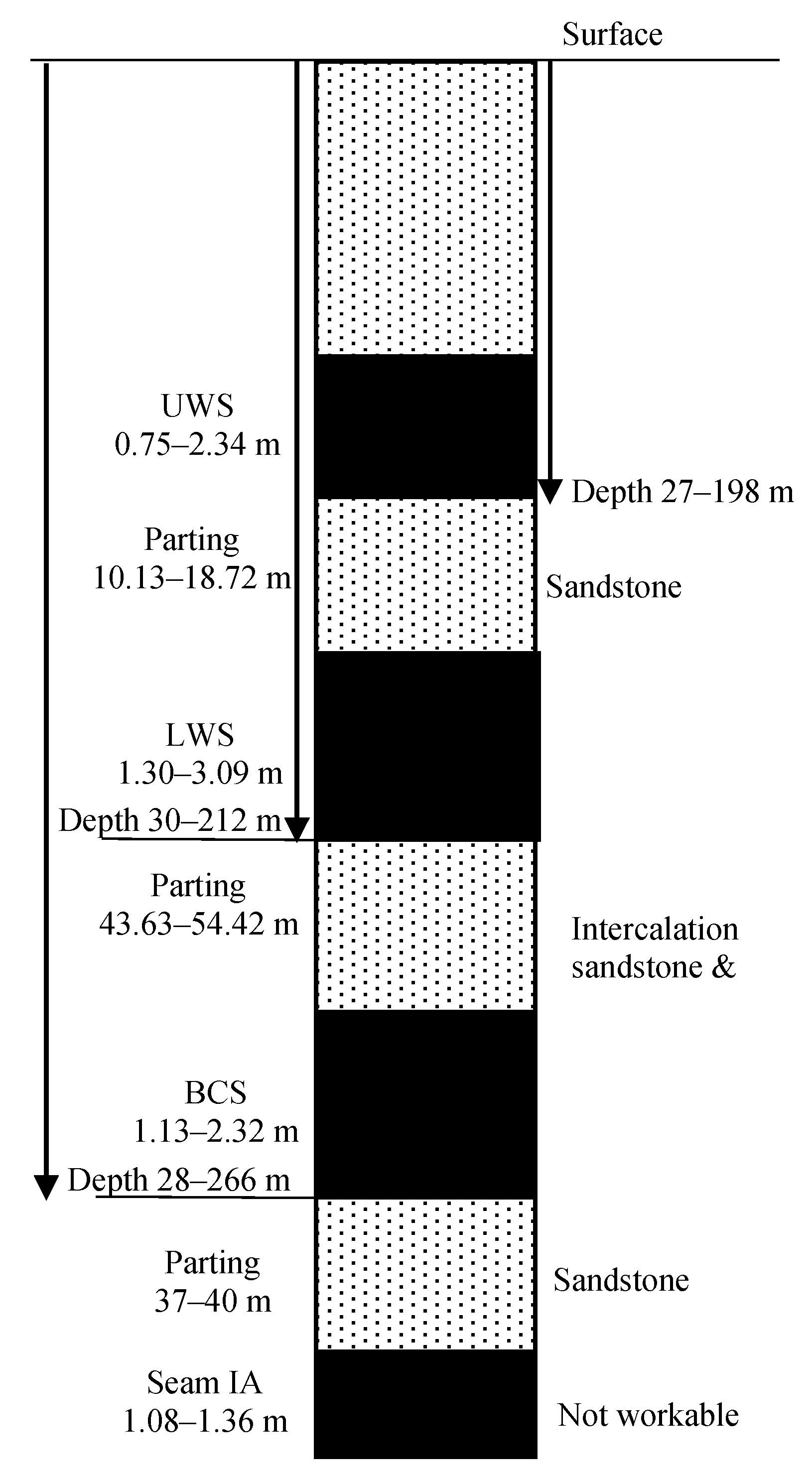
Four coal seams, namely, Upper Workable Seam (UWS), Lower Workable Seam (LWS), Bagdona Coal Seam (BCS), and Seam IA, have been established by drilling in the Tawa-I Underground Mine. The variation in thickness of different seams and their intervening parting, as encountered in different boreholes, is mentioned in
Figure 1 and
Figure 2.
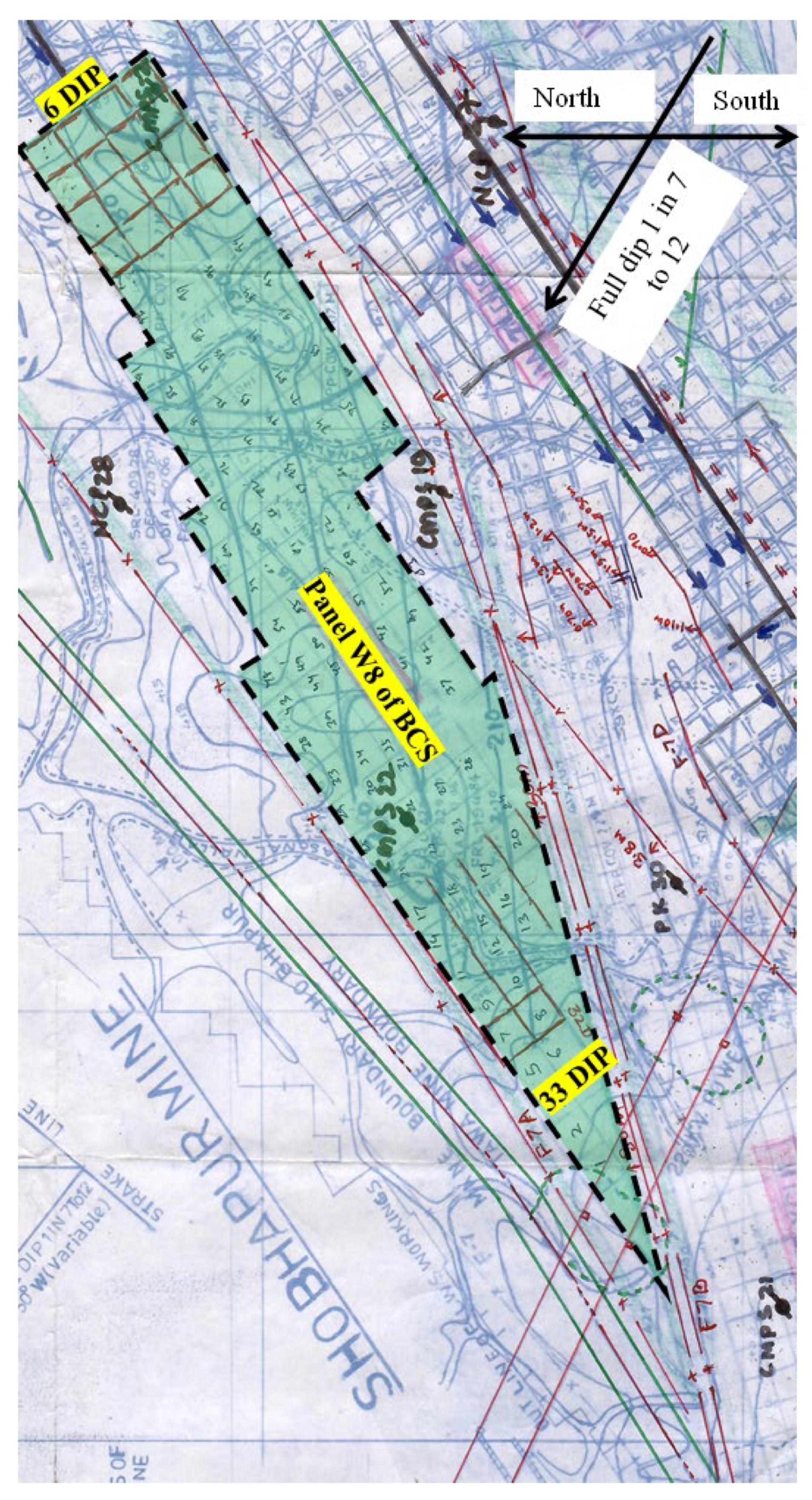
Presently, the panel (
Figure 3) is being developed on pillars (35.7 m × 31.2 m) and galleries (3.8 m × 1.8 m) by the Bord and Pillar Mining Method. It has been planned to depillar the conventionally developed pillars in the panel using mechanized Continuous Miner (CM) technology. Furthermore, the Continuous Miner (CM) must extract the sides of the pillar to widen the existing galleries from 3.8 m to ensure adaptability.
Depillaring operation in the panel needs a preparatory arrangement for the widening of galleries by cutting the sides of the pillar using CM for its easy maneuverability and adaptability and advanced installation of geotechnical instruments. A Shale roof of varying thickness of 3–5 m is present above the coal seam in the panel. A fault with a 1.5 m throw is running from 4 Dip to 13 Dip between 63L and 64L (
Figure 3) and is further surrounded by two major faults. The panel is lying below a panel that had been depillared with the caving-in LWS at an average parting of 50 m. A maximum subsidence of 1.6 m has been reported to date in the Tawa-I mine in the panel E2 section of the LWS. The maximum angle of the draw has been observed up to 11° in the E6 district of the LWS, which was depillared 11 years ago. The geo-mining conditions of the panel are mentioned in
Table 1. A number of developments have been made for the design of geotechnical elements [
1,
2,
3,
4] involved in working with Continuous Miner Technology. Furthermore, researchers have also investigated methods to effectively manage the challenging cavable roof.
The literature on strata control and mining safety in coal mines presents various strategies and technologies aimed at improving safety, stability, and efficiency in underground mining operations. MSHA [
5] outlines essential guidelines for managing roof and rib stability, emphasizing proactive measures such as roof bolting and rib control to prevent roof falls. Jayanthu [
6] focuses on the application of geotechnical instrumentation and numerical modeling to monitor and predict strata behavior, thus, aiding in better risk assessment and safety management. Konicek et al. [
7] explore the use of long-hole destress blasting to prevent rockbursts in deep coal mines, highlighting its effectiveness in reducing stress concentrations and maintaining stability in high-stress environments. Huang et al. [
8] discuss hydraulic fracturing technology to manage hard roof conditions, demonstrating its potential to enhance roof stability by reducing stress and improving permeability. Xu et al. [
9] examine mining-induced strata movement and roof behavior, providing insights into the importance of monitoring and analyzing strata to optimize roof support systems and enhance safety. Kang et al. [
10] propose innovative intelligent mining technologies and real-time monitoring for deep coal mines, addressing challenges related to high geological stress and complex strata behavior. Guo et al. [
11] investigate roof strata behavior and support resistance for ultra-thick longwall top coal caving panels, offering solutions for maintaining safe working conditions in high-stress environments. Jangara and Ozturk [
12] explore the design of longwall top coal caving for thick coal seams with poor surrounding strata, providing recommendations for effective support systems and safety protocols. Kumar et al. [
13] examine controlled fracturing of overlying strata to ensure the safe extraction of thick coal seams. Wang et al. [
14] investigate roof presplitting techniques in non-pillar coal mining, focusing on reducing stress concentrations in hard roof conditions. Finally, Chang et al. [
15] present safety and high-recovery mechanisms for the initial mining of complex coal seams with thick, hard roofs, emphasizing the need for advanced support systems and innovative technologies for safe and efficient operations. Together, these studies contribute valuable insights into the development of safer, more efficient mining practices in challenging coal mining environments.
This paper mentions the design of underground structures based on empirical and simulation studies for better strata control management with CM Technology in a trialed mechanized depillaring panel of the Tawa-I mine.
2. Empirical Approach to the Design of Underground Structures
Bagdona Coal Seam (BCS), after access through inseam drifts, has been extensively developed using the Bord and Pillar Mining Method (BPMM). The immediate overlying LWS was already developed and depillared many years ago. Presently, development operations are in progress in the panel using a Load Haul Dumper (LHD) and belt conveyor combination. It has been proposed to depillar these developed pillars with the combination of Continuous Miner/Shuttle Car/Quad Bolter/Feeder Breaker technology.
2.1. Cavebility Index
On the basis of different field experiences, the caving characteristics of overlying strata are quantified in terms of the Cavability Index (
I) [
16], which is defined as:
where σ is the uniaxial compressive strength in kg/cm
2,
l is the average length of core in cm, T is the thickness of the strong bed in m, and the factor
n has a value of 1.2 in the case of uniformly massive rocks with a weighted average of RQD of 80% and above and in all other cases, the value of n is equal to 1.
The Cavability Index of the immediate roof of the panel is estimated to be 7260, which falls under the category of roof cavable with difficulty (
Table 2). Since there is no evidence of water in the overlying strata, it is anticipated that roof falls will be delayed in the goaf during work in the panel.
2.2. Width of Gallery
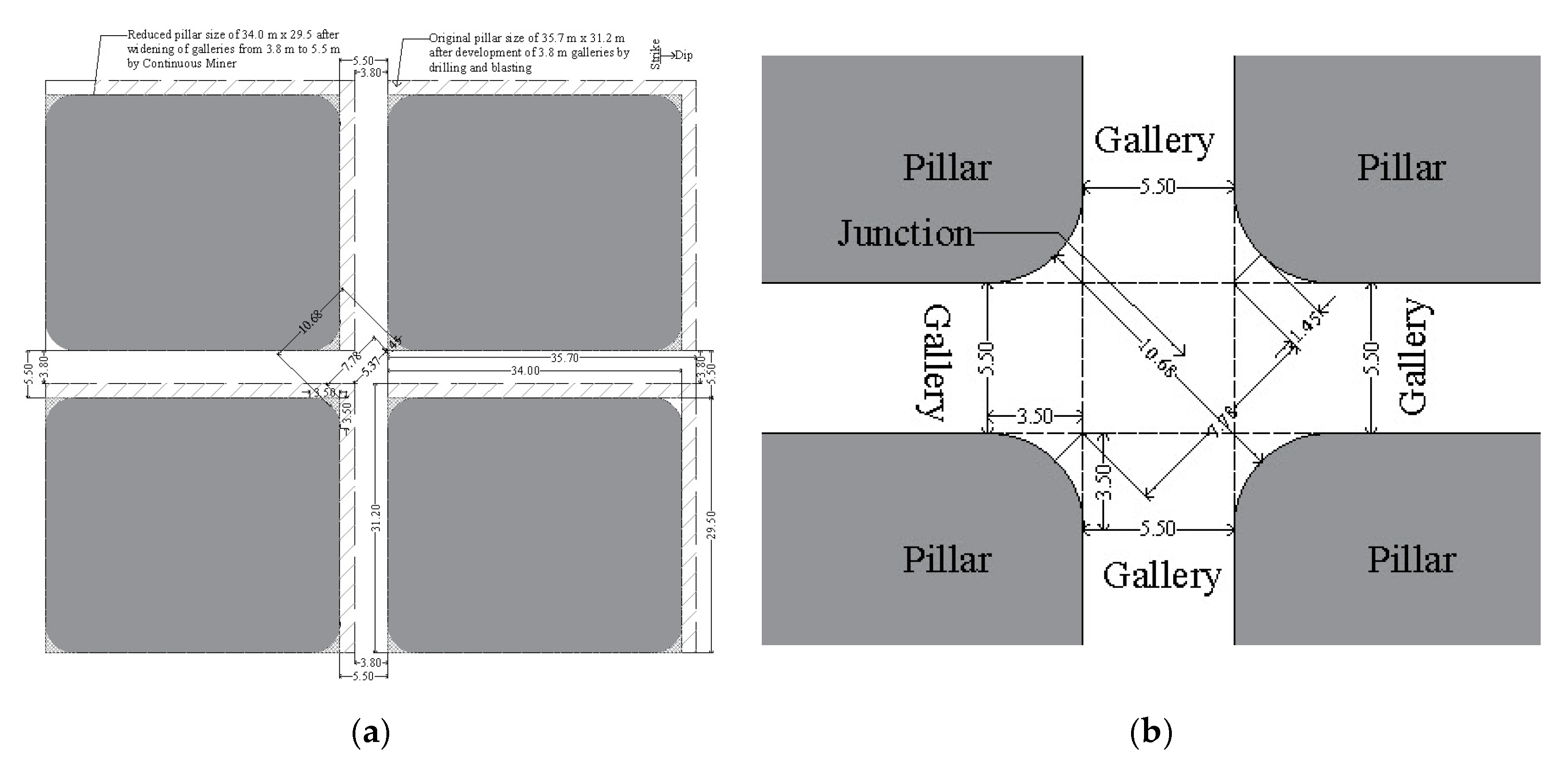
Existing galleries of 3.8 m need to be widened for adaptability of the CM (
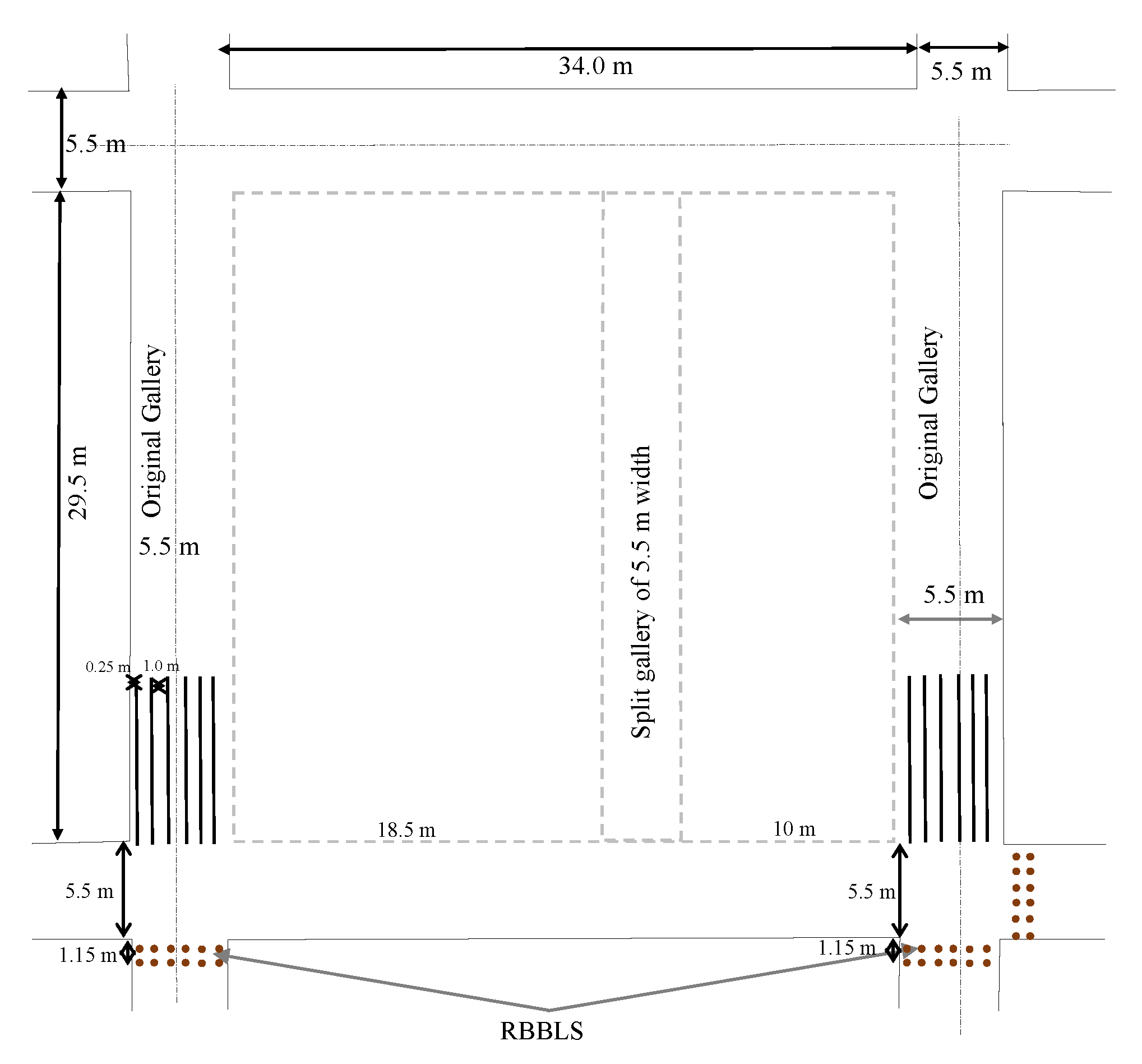
Figure 4a) by cutting the sides of the coal pillar measuring 35.7 m × 31.2 m (corner-to-corner). Considering the extent of spalling, frequency of slips/joints/discontinuities present in the panel, and available case studies of mechanized depillaring (MD) panels using CM Technology in different coalfields of India, it is proposed here to widen the 3.8 m width of the gallery to 5.5 m only. It is suggested to extract the sides of the pillars of 1.70 m in an L-shaped manner for efficient utilization of the CM in the panel. The extraction of the sides of the coal pillar will reduce its size from 35.7 m × 31.2 m (corner-to-corner) to 34.0 m × 29.5 m (corner-to-corner). Furthermore, it will also reduce the strength of the pillar. Considering the length of the machine to be 11.9 m, it will be difficult for the CM to turn around the junctions of the 5.5 m width of the gallery. A diagonal length of around 10.50 m is required around the junction for turning the entire length of the CM; therefore, it is also proposed here to reduce the corners of the pillar as shown in
Figure 4b. Around 10.68 m of diagonal length will be available after the extraction of corners around the junction, which provides a sufficient turning radius for the movement of the CM. It has also been found that the sharp 90° corners become rounded ultimately due to induced stress-driven spalling. The suitability of the 5.5 m width of the gallery has also been simulated in numerical models and found to be appropriate, which is presented in the section on Numerical Modeling.
2.2.1. Safety Factor of Pillar and Fender
Sheorey [
17] developed an empirical formula (Equation (2)) for estimating of pillar strength, which is well established in Indian coalfields for pillar design.
where S = pillar strength (MPa), σc = uniaxial compressive strength of coal (MPa), h = working height (m), H = depth of cover (m), and we = effective width of the pillar (m) = 4A/P, where A is area and P is the perimeter of the pillar.
The Tributary Area Method [
18] is used to calculate load over pillar and fender. The formation of a pillar by driving galleries all around disturbs the state of virgin stresses, keeping the total magnitude of the overlying strata weight γH constant. It is normally assumed that the entire weight overlying a tributary area is supported by solid pillars. The stress on pillar (P) is estimated using the Tributary Area Method as given in Equation (3).
where
H = depth cover (m), B = width of the gallery (m), W1 = length of pillar (m), W2 = width of pillar (m), and γ = unit rock pressure (0.025 MPa/m).
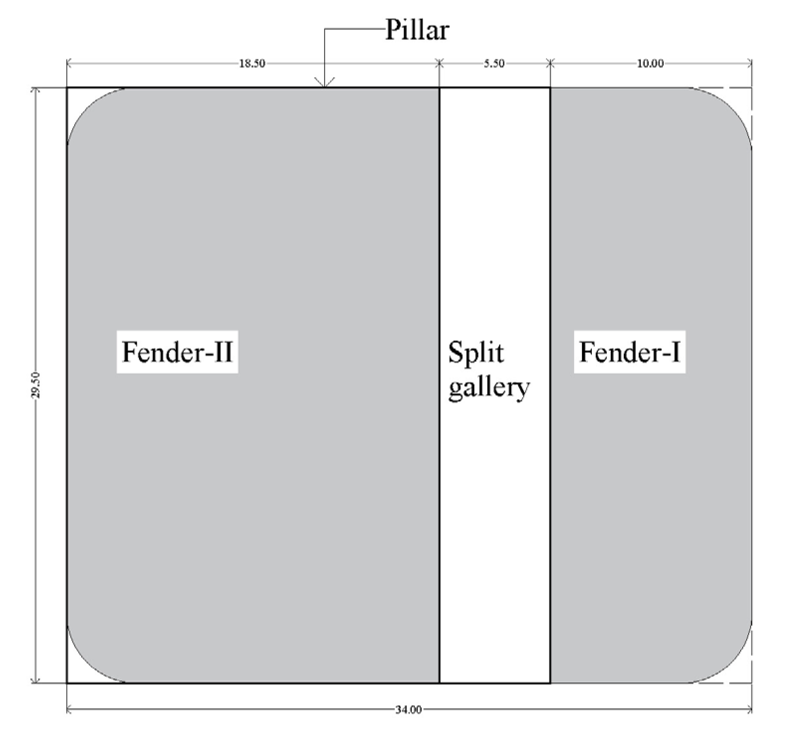
The abovementioned empirical formula has been used to estimate the strength of the pillar and fender that will be formed during mechanized depillaring in the panel. Here, the fender is half of the pillar after it splits into two unequal parts (
Figure 5). Unequal division has been suggested to control the cut-out distance (COD) as per the geo-mining conditions. Considering the variation in the depth of the cover of the panel, the safety factor of the pillar and fender is estimated based on the maximum 266 m depth of cover. The safety factor of the pillar is estimated using the strength and load on the pillar, as mentioned in
Table 3. The estimated safety factor of the pillars (4.28) and fenders (1.64 and 2.84) for the panel seems to be competent for the pillar extraction subjected to regular caving and less disturbance due to geological discontinuities in the working area.
2.2.2. Safe Cut-Out Distance
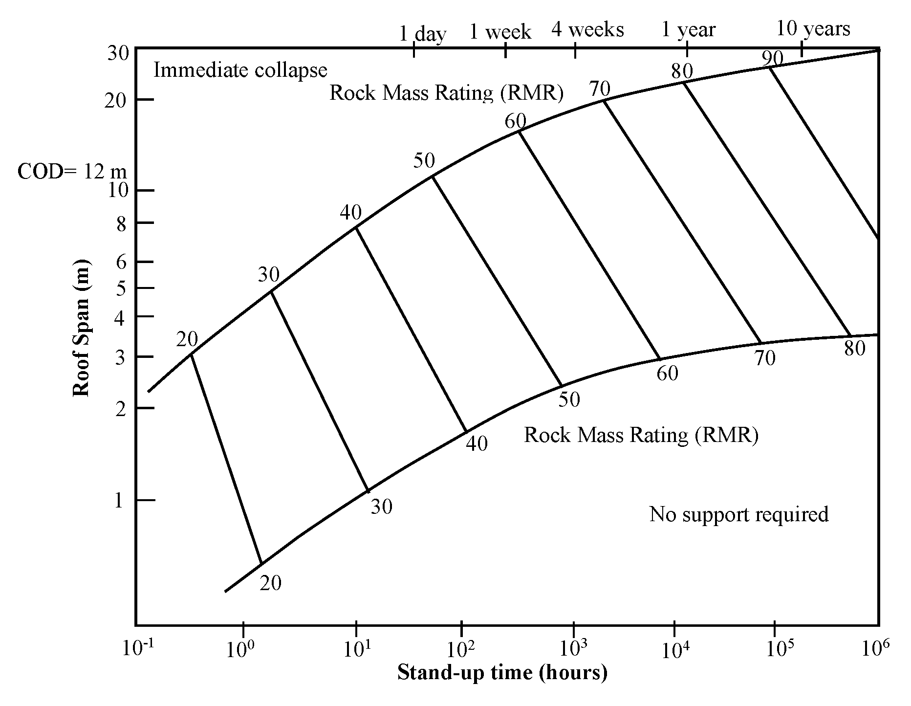
Safe Cut-Out Distance (COD) is defined as the maximum length of the unsupported span between the advancing face and the nearest supported area, or the width between the side pillars, i.e., the width of excavation. As per the available literature review, Bieniawski [
18] system (
Figure 6) is found to be a suitable approach for estimating the safe COD (unsupported maximum span) during MD in the panel. The observed RMR value of the immediate roof strata of BCS is 50.40, with adjustments, as the seam was developed through solid blasting. The roof of the BCS is sandy shale, with an average value of elastic modulus of the immediate roof (E) as 2.0 GPa, and the width of the gallery has been fixed at 5.5 m.
Bieniawski [
18] used the Rock Mass Rating (RMR) developed by Bieniawski [
19,
20,
21] for stand-up time and unsupported span of roof (
Figure 6). The Coal Mine Roof Rating (CMRR) developed by Molinda and Mark [
22] was used to design cut-out distances in US underground mines. Bauer [
23] suggested an empirical formulation (Equation (4)) to design cut-out distance based on the Coal Mine Roof Rating (CMRR), the width of the gallery, and depth.
where D is the cut-out distance (m), R is the Coal Mine Roof Rating, W is the width of the gallery (m), and H is the depth of cover (m). Using this relationship (Equation (4)), the cut-out distance is found to be 10.67 m for an RMR of 50.40, gallery width of 5.5 m, and maximum depth of cover of 266 m.
Mandal et al. [
24] proposed a relationship (Equation (5)) to estimate the safe convergence value based on COD, RMR, and width of the gallery (m).
where C is the convergence of the immediate roof (mm), W is the width of the gallery (m), R is the Rock Mass Rating, and D is the cut-out distance (m). For a safe convergence of 5 mm, this relationship estimates a cut-out distance of 16 m for a gallery width of 5.5 m and an RMR of 50.40.
Saharan et al. [
25] used the concept of Bieniawski [
18] and Mark [
26] to design COD for three Indian coal mines. Kumar et al. [
27] attempted to define the safe and limiting value of roof sagging of 5 mm for a safe design of COD. Kumar et al. [
27] proposed a relationship (Equation (6)) to estimate the COD based on elastic modulus and width of the gallery, considering a few case studies of MD in Indian coalfields.
where D is the cut-out distance (m), E is the elastic modulus (GPa), and W is the width of the gallery (m). Using this relationship, the cut-out distance is found to be 9 m for a 5.5 m gallery width and 2.0 GPa elastic modulus of the immediate shale roof.
Based on the (
Figure 6) by Bieniawski [
14], the estimated maximum unsupported span, i.e., COD for the development of galleries comes to be around 12.0 m for the existing conditions of roof rock mass above BCS. Bieniawski [
18] developed the relationship to estimate the COD for a tunnel, which has a single opening. Considering the existing conditions in the panel, multiple openings, and maximum use of the CM, the COD in the panel is maintained at 11.0 m. The estimated value of the COD as 11.0 m should also be adopted during the drivage of the original/split gallery and slices in the panel. The exposed COD should be supported instantaneously after the dressing of the roof before the next cut by the CM in the original/split gallery only, not in slices. This estimated value has also been validated on numerical models through simulation. A simulation study for the geo-mining conditions of the panel is carried out to study the variation in roof deformation for different lengths of unsupported span. The cutting sequences during the development/splitting of a pillar by CM are shown in
Figure 7.
2.3. Extent of Pillar Spalling
Wilson [
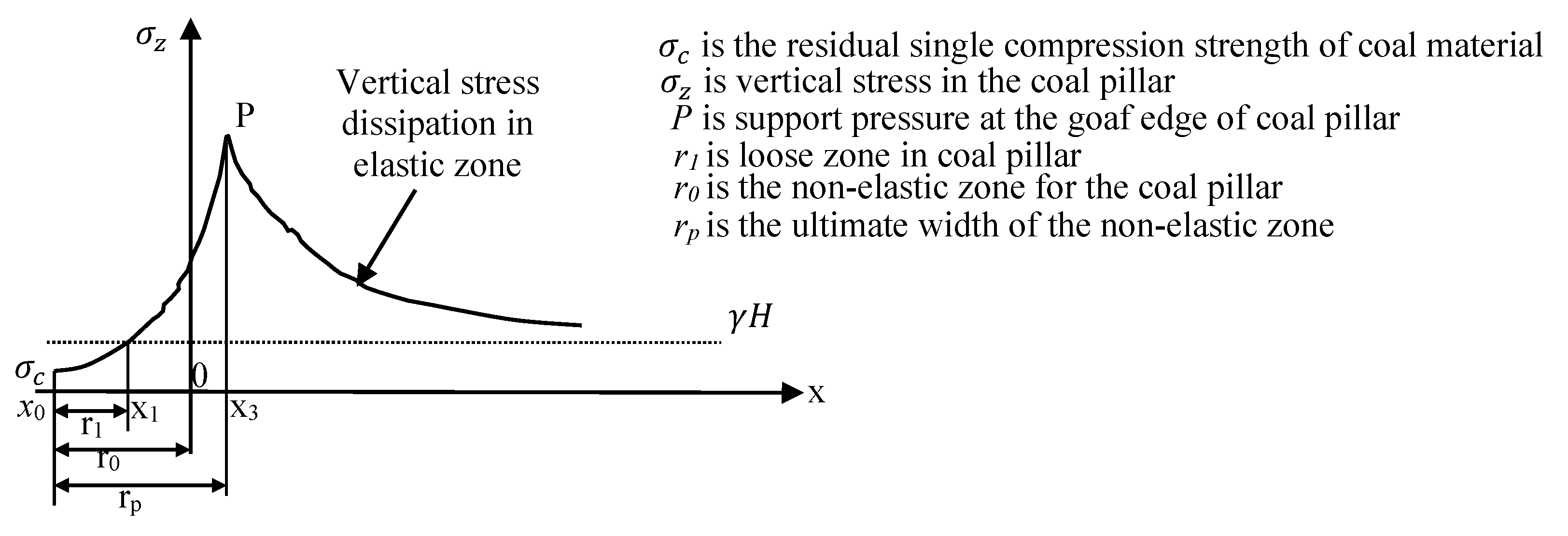
28] developed an empirical equation to estimate the non-elastic zone based on the height of extraction and the depth of cover of the working seam. The literature survey and different field investigations in Indian coalfields have found that a higher value of vertical-induced stress is experienced by coal pillars/fenders/ribs/snooks at the goaf edge during MD. This phenomenon is more pronounced when MD is being carried out under a difficult and massive roof at a deeper cover. The deterioration of the pillar develops in the form of the non-elastic zone as side spalling on the outer part and the inner part remains under the elastic zone. Further, the non-elastic part is divided into a loose (spalled) zone and a plastic zone [
29,
30,
31] (
Figure 8). The spalled part of the pillar is almost dislodged, hanging, and incapable of providing any resistance against load, whereas the plastic part of the pillar remains attached to the pillar, which provides confinement against the load. Thus, it results in fracturing and spalling of corners and sides of pillars, reducing the overall size and strength of a pillar. It ultimately affects the size and shape of the rib/snook to be left and the performance of the roof bolt-based breaker line support (RBBLS) and instrumentation plan considering the location of instruments to be installed for strata monitoring around the goaf edges. An attempt has been made to estimate the extent of pillar spalling in the panel. Based on the pillar height of 1.8 m and the maximum depth of 266 m in the panel, the non-elastic zone is found to be around 2.36 m with a loose/fractured zone of 1.00 m and a plastic zone of 1.36 m. The spalled portion has been already treated during the reduction in the corners of pillars by 1.45 m for the adaptability of CM.
2.4. Applied Support System in Developed Workings
An attempt has been made to design a support system for the original gallery and junction/intersection using the available empirical approaches [
32], which is also studied using rock load height (RLH) on numerical models in a simulation software package, considering the site conditions. Required support resistance against the estimated rock load at the gallery and junction is calculated using the bearing/anchorage capacity of the applied supports. Supports at the original gallery and junction are designed by considering a support safety factor (SSF) (Equations (8)–(11)) of 1.5 or more for both the empirical and numerical simulation approaches. Basically, the support design depends on parameters like gallery width, rock mass rating (RMR), and unit weight of immediate roof strata.
2.4.1. Rock Load
The efficacy of the support system for the original gallery and junction of developed workings of the panel is estimated using the empirical relationships given as Equations (7) and (8).
where B = gallery width (m),
= dry unit weight of roof rock (t/m
3), and
stands for Rock Mass Rating.
2.4.2. Support Resistance
The anchorage capacity of resin grouting material required for the estimation of support resistance is tested to be 20 t during the field investigation. Support density is estimated using the number of supports (roof bolts) multiplied by the anchorage/bearing capacity of that support. Considering these parameters, support resistance is calculated using Equation (9).
2.4.3. Support Safety Factor
The support safety factor is calculated using Equation (10) to establish the effectiveness of the support system.
2.4.4. Design of Applied Support
The immediate roof of the panel was examined during the field visit and found to be competent and dry. The pillars, of 39.5 m × 35 m (center-to-center), with galleries of 3.8 m, are being developed by drilling and blasting in combination with LHD for hauling and belt conveyor for the transportation of coal to the surface. The pillars were found to be intact, and there were no observations of side spalling during the field visit. Furthermore, there was no evidence of water seepage from the roof, and the shale in the roof was found to be intact within the panel during the field visit. The bearing capacity of the resin-grouted roof bolt and RMR were found to be 10 t (in 8 h) and 50.40, respectively. Rock load, support resistance, and SSF are estimated for gallery and junction using Equations (8)–(11) for suitable support design (
Table 4) of developed workings of the panel by drilling and blasting. Further, it was proposed to widen the existing galleries from 3.8 m to 5.5 m; therefore, the roof bolt pattern for such widened galleries and junctions is mentioned in
Table 4 and shown in
Figure 9.
2.5. Design of Rib/Snook
Recently, empirical formulas [
1,
2,
3] have been developed to estimate the strength, area, width-to-height ratio, and equivalent width of rib/snook for Continuous Miners based on case studies of 39 mechanized depillaring panels of different Indian coalfields (Equations (11)–(14)), considering safety factor of rib/snook of 0.30–0.35.
where
= strength of rib/snook (MPa), w = equivalent width (m), H = depth of cover (m), and h = height of extraction (m), A = area, R = nature of roof in terms of RMR,
equivalent width (m).
An attempt is also made to estimate the strength of different sizes of rib/snook using formulations (Equations (12)–(14)). The strength of different sizes of rib/snook (
Figure 10) formed during MD in the panel is also presented in
Table 5.
For the panel, H = 266 m (maximum), RMR (R) = 50.40, and h = 1.80 m, the competent area of the outby rib/snook (A) = 47.83 m2, having an equivalent width of 6.16 m with a width-to-height ratio of around 3.42, is required during the extraction of pillars by CM. Therefore, a rib/snook size of 2.00 m × 18.50 m × 3.00 m, having an area of around 71.60 m2 with a width-to-height ratio of around 3.81, is found to be suitable for the considered geo-mining conditions of the panel. This size of rib/snook is the minimum area to be maintained during judicious reduction, including the effects of pillar spalling (plastic and loose zone). Therefore, a rib/snook size of 3.00 m × 18.50 m × 3.00 m (area of 81.60 m2, equivalent width of 7.62 m, and width-to-height ratio of 4.23) is proposed to be left during MD operation, which may be further reduced up to 2.00 m × 18.50 m × 3.00 m (area of 71.60 m2, equivalent width of 6.86 m, and width-to-height ratio of 3.81) due to induced stress-driven side spalling of pillars/fenders. Further, different sizes of rib/snook in this panel are also tested during the numerical simulation study, explained in the later section.
2.6. Goaf Edge Support
Roof bolt-based breaker line support (RBBLS) is proposed to be installed at the goaf edges in the CM panel. Rock load at the goaf edges is estimated by multiplying the rock load height (RLH) estimated through equations mentioned below (Equations (15)–(17)) by rock density (
. Relationships for RLH at the proposed three different positions of the RBBLS at the goaf edge have been developed [
4] for different outby distances from the edge of the pillar at the goaf edge, which are given below.
For 0 m outby from goaf edge
For 1 m outby from goaf edge
For 2 m outby from goaf edge
where H is the depth of cover (266 m), and R is the RMR (50.40). Using the above equations, RLH is found to be 3.41 m at 0 m outby, 2.68 m at 1 m outby, and 2.04 m at 2.0 m outby from the goaf edge. It is not possible to use a 2 m length of roof bolts, considering the 1.8 m average thickness of the coal seam. Based on the equations and extent of spalling up to 1 m of the pillar present at the goaf edges, RLH at 1.15 m outby from the goaf edge has been used for the design of breaker line support at the goaf edge, which is shown in
Figure 11. It is proposed here to install two rows of (seven bolts in each row) roof bolts of 1.70 m length at 0.75 m grid pattern located at a 1.15 m outby from the goaf edge (corner of the pillar facing the goaf line) along the middle position of the rib/snook for safe MD of the panel, as shown in
Figure 11. Another two similar sets of RBBLS are to be installed in a row along the midrib in the original/split galleries. It should be mentioned that the practice of RBBLS will enhance efficiency and reduce the cost and cycle time. The normal practice of installing 1.5 m lengths of bolts should be avoided at the location of RBBLS. The design of RBBLS has also been studied on numerical models and results have been validated with the empirical formulation, presented in the numerical simulation section.
3. Hanging Roof Span in Goaf for Caving of Overlying Strata
Van der Merwe [
33] developed a relationship to estimate the roof span for roof fall (
Figure 12). There are three possible fundamental modes of roof fall in the goaf. The tension failure mode for overlying strata in goaf may be triggered when the weight of the hanging roof span is more than the tensile strength of the rock, or the tensile strength across a discontinuity plane. Induced tension at the goaf edges of the roof plate may be another potential mode of failure that will occur when the mathematical sum of the induced tension and the compressive horizontal stress is greater than the tensile strength of the rock. Sliding of the rock blocks along pre-existing vertical or near-vertical joint planes may be another mode of failure that will occur when the weight of the block exceeds the cohesion and frictional resistance of the joint planes.
Most of the roof fall occurs mainly under shear failure and failure by induced tension due to roof sagging. Bending-induced tension is the most likely failure mode, which is persistent in Indian coalfields. Overlying strata in a sedimentary formation consist of a number of layers with different thicknesses and stiffnesses. The first major fall often occurs when the face advance is equal to the panel width. After the first major fall, the continuity of the roof beam is lost and the overlying strata behaves like a cantilever. After the formation of the cantilever, the continuity of strata is lost, and horizontal stresses diminish. After the occurrence of a major roof fall, the overburden plates become discontinuous, and the roof beam analogy is not valid.
The caving angle is the angle between the vertical line at the goaf edge and the inclined line to the strata over the caved zone (
Figure 13). It remains almost equal to the angle of the draw in subsidence, which varies between 20 and 30° for the Indian coalfields (
Figure 13). The angle of the draw of 11° has been observed in the Tawa-I mine in the E6 district of LWS, which was depillared 11 years ago. Considering the thickness, strength, and massiveness of the overlying strata of the proposed panels of the mine, the caving angle is considered to be around 11° from the vertical. As per Palchik [
34], the bulking factor (BF) of different rock masses is found to range between 1.05 and 1.84, and it is found to be around 1.1 for roof rock having moderate compressive strength (20–30 MPa). Therefore, the height of caving during roof fall in the goaf is found to be around 18 m (taking 1.8 m as the height of extraction) for the panel.
Expected Area of Roof Falls
For the panel, an average hanging roof span of 32 m (around 8700 m2 for a panel width of 271 m) in the panel is found to be inducing the first major fall of the beam roof, forming a cantilever. Furthermore, a roof span of around 21 m (around 5687 m2 for a panel width of 271 m) in the panel is found to be causing the subsequent goafing and caving of the cantilever.
Furthermore, the actual shape of the panel is asymmetrical (
Figure 3) right from the start of 33DW. In the initial three rows of the panel, there is only one pillar width (33DW-31DW); thereafter, two rows of two pillars (31DW-29DW), and then two rows of three pillars (29DW-27DW). There are four pillars in the next three rows (27DW-24DW), and thereafter the actual width of five pillars (271 m) is found from 24DW. The width of the panel is an important factor for the occurrence of caving in the goaf. Roof fall will not take place in the panel during the initial five rows of pillar extraction, even after a roof span of 8700 m
2 or more due to insufficient panel width (33DW-29DW). The first main roof fall is expected to occur during or after the extraction of the pillar in 29DW-28DW.
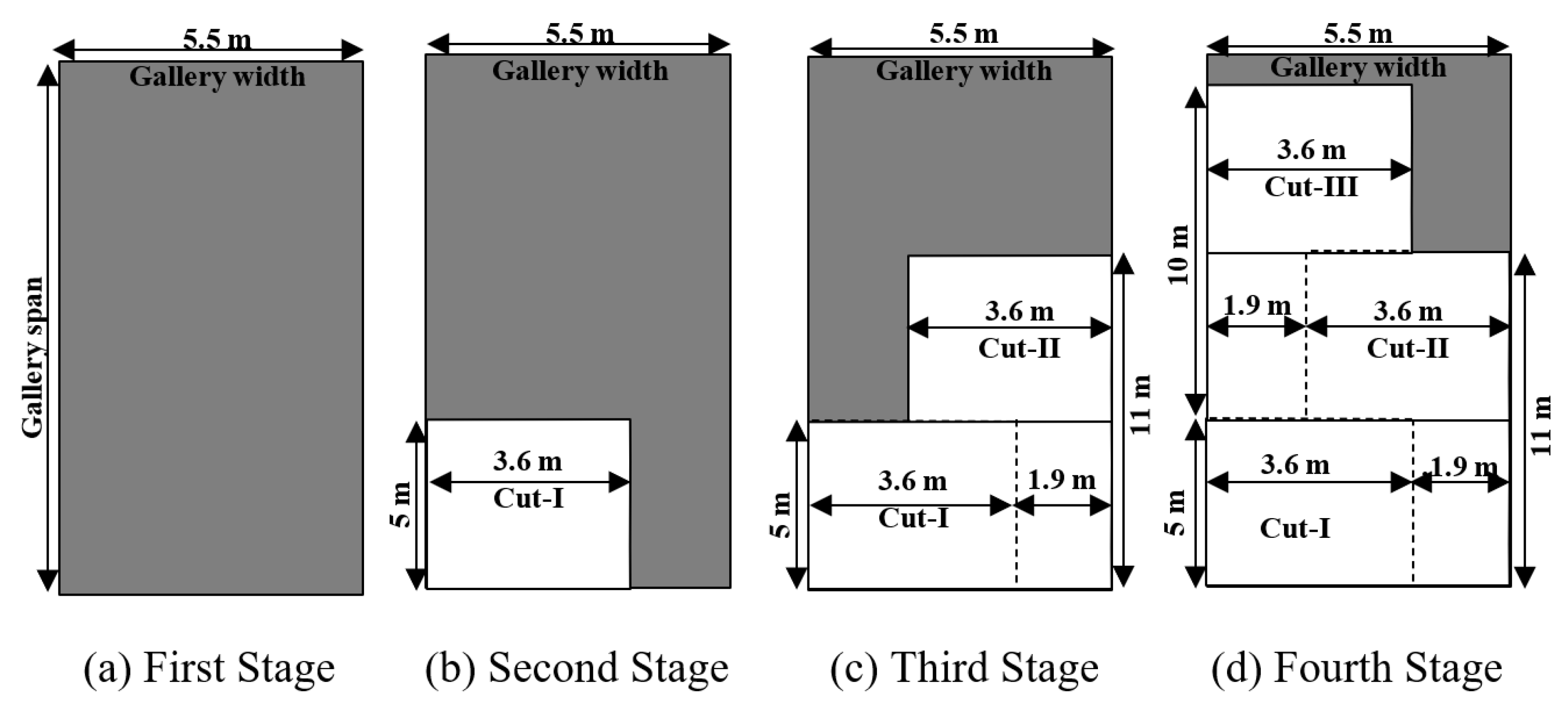
The splitting of pillars is to be performed only one pillar in advance of the pillar under extraction, considering the safety of the work. A sequence of driving of split and slice galleries mentioned in
Figure 11, is to be followed during the MD operation. Considering the safe COD value, the split gallery is to be driven in three cuts as first, second, and third sequences of 10 m, 10 m, and 9.5 m, respectively, in each length of cut (
Figure 7).
4. Numerical Simulation
A systematic numerical modeling study is conducted on simulated models to visualize the performance of different empirically designed geotechnical structures under the geo-mining conditions of the panel. Taking different advantages of numerical modeling, the elastic model of the simulation package is used to simulate the rock strata at the goaf edge. Here, the rock mass failure criterion developed by Sheorey [
35] is used for the analysis, which uses the Rock Mass Rating (RMR) of Bieniawski [
9,
20,
21] for reducing the laboratory strength parameters into the corresponding rock mass values. However, this RMR is not frequently used by Indian coal mines, where CMRI-RMR [
32] is commonly used. It is found that the application of CMRI-RMR in the failure criterion provides reasonable results and is used in this study.
The bulk and shear modulus are evaluated using Young’s modulus and Poisson’s ratio by the following equations.
where E is the Young’s modulus in GPa, K is the Bulk modulus in GPa, G is the Shear modulus in GPa, and
is Poisson’s ratio. Average in situ stresses [
36] is used according to the following equations:
where H is the depth cover in meters,
is vertical in situ stress,
is major horizontal in situ stress, and
is minor horizontal in situ stress. In order to assess the stability of natural support and the exposed span, safety factors are calculated using the Sheorey [
35] failure criterion in the numerical models as given below:
where
is the triaxial strength of rock mass in MPa,
is confining stress in MPa,
is the compressive strength of the intact rock in MPa,
is the tensile strength of the intact rock in MPa, b is the exponent in failure criterion, which controls the curvature of the triaxial curve,
is the compressive strength of rock mass in MPa, and
is the tensile strength of rock mass in MPa.
The factor of safety is defined as
where
is induced major principal stress in MPa and
is induced minor principal stress in MPa. From these, the rock mass shear strength,
; the coefficient,
and the angle of internal friction,
are obtained as shown in Equations (28)–(32), which are used as Mohr–Coulomb strain softening parameters in the simulation package used during stress–strain characteristics of different sizes of rib/snook in the two panels of the Tawa-I mine.
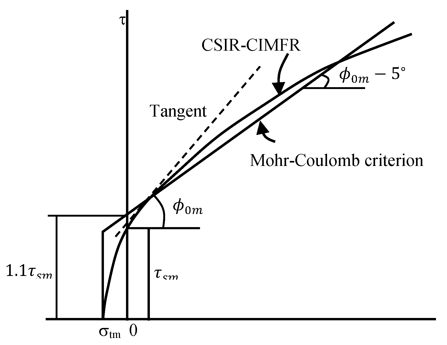
It is observed that the values of shear strength,
and friction angle,
so determined as per Equations (30)–(32), needed slight adjustment to incorporate the fact that the MCSS plasticity model in the simulation package uses the linear Mohr–Coulomb criterion, while the Sheorey criterion is non-linear. To compensate the difference in nature, the value of
obtained from the Sheorey criterion is increased by 10% and that of
is reduced by 5° to use them as MCSS parameters (
Figure 14).
4.1. Simulation of Proposed Panels
Numerical models are developed to simulate the geo-mining conditions of the panel in order to estimate the safe width of the widened gallery, cut-out distance, size of rib/snook, and pattern of roof bolts-based breaker line support (RBBLS).
4.1.1. Simulation for Design of Gallery Width, Cut-Out Distance, and Rib/Snook
A simulation of a single pillar is carried out for estimation of safe split gallery width, cut-out distance, and strength of different sizes of rib/snook in the panel. Taking advantage of the existing symmetry conditions of pillar formation, a single pillar considering only three layers (floor, coal, and roof) is modeled in the simulation software for the estimation of the strength of different sizes of pillars whereas different layers as mentioned in
Table 6 are considered for the simulation of safe gallery width and COD.
Furthermore, vertical roof displacement is observed over numerical models as per
Table 6 to determine a safe gallery width and a cut-out distance based on a safe limiting value of roof sagging of 5 mm. The estimated safe width of the gallery is found to be 5.5 m for the panel (
Figure 15). Based on experiences of workings under similar geo-mining conditions in different Indian coal mines, the safe width of the gallery is estimated in the model, considering 5 mm [
37] as the limiting value of roof sagging to induces permanent movement (plastic in nature) in the galleries to be widened/split/slice (
Figure 15). It is found that the roof of the gallery is stable without a considerable amount of roof deformation after the proposed gallery width of 5.5 m (
Figure 15). A pillar size of 34.0 m × 29.5 m (corner-to-corner) and a gallery width of 5.5 m are found suitable for panel, respectively, as per the numerical simulation study and found to be validating the results of empirical formulations.
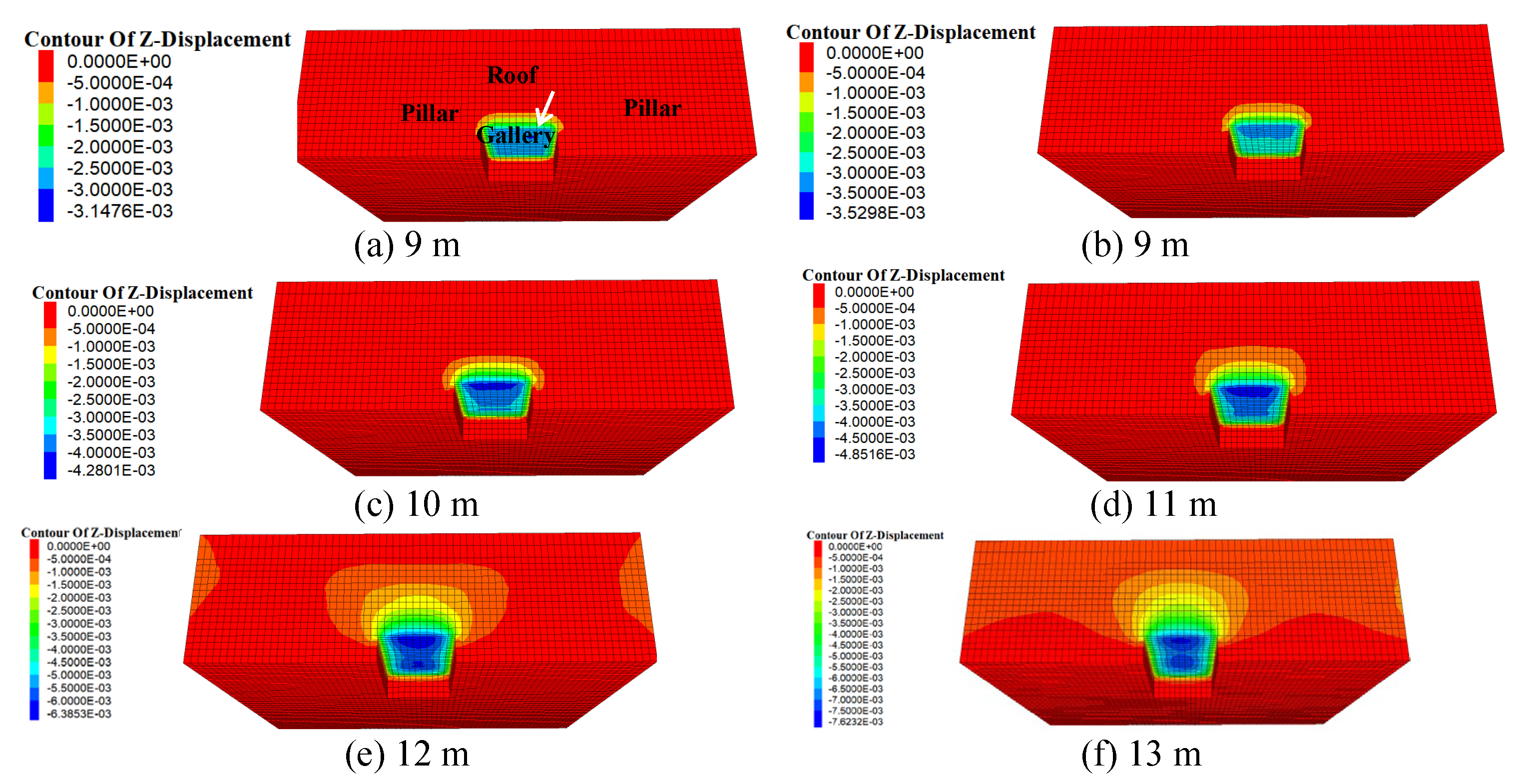
The estimated maximum unsupported span, i.e., cut-out- distance (COD) for a 5.5 m wide gallery in the panel is found to be around 11 m (
Figure 16). Based on experiences of working in different Indian coal mines, the COD in the model is estimated, considering 5 mm [
37] as the limiting value of roof sagging to induce permanent movement (plastic in nature) in the split/original galleries/slice to be driven. It is found that pillars are standing without a considerable amount of roof deformation after the proposed drivage of 11.0 m, which validates the results of empirical formulations.
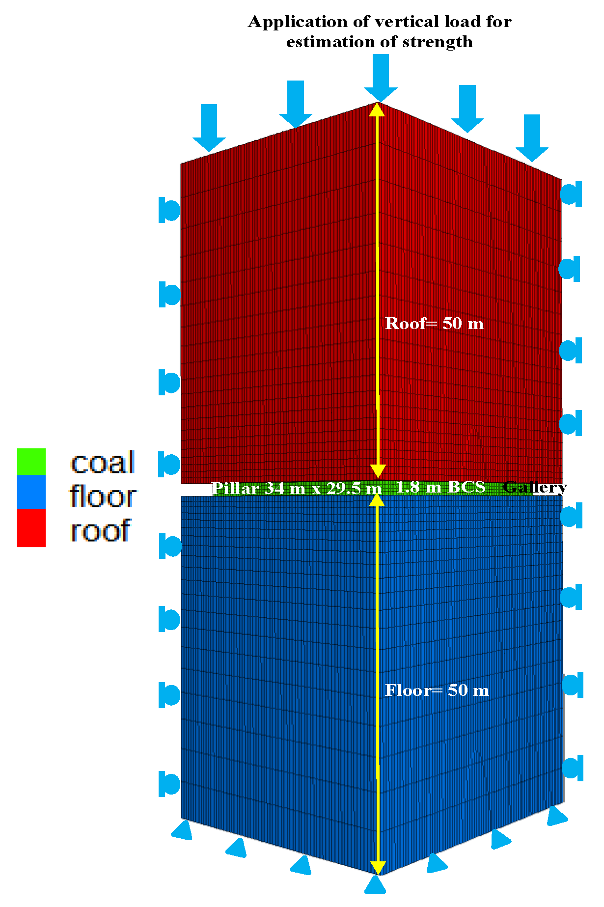
The upper face of the model is fixed for the estimation of the strength of ribs/snooks, with the application of a standard calibrated velocity applied in the vertical direction (
Figure 17) after developing galleries. Displacements in the vertical and horizontal directions are fixed at the bottom, and four vertical symmetrical planes of the model are constrained, which are considered boundary conditions during the numerical modeling. The standard size of the model is tested during the numerical modeling, considering the limitations of the computational memory and runtime requirements; 50 m of the roof and 50 m of the floor are modeled with a 1.8 m coal seam in the panel (
Figure 17). A coal seam of 1.8 m thickness is considered a strain-softening model, while the roof and floor are treated as elastic constitutive models. In situ stresses are developed in the model before studying the effects of the mining operations. It is carried out to redistribute the stresses in the model and equilibrium conditions are reached, replicating the actual site conditions. Excavation operations are carried out in the model and equilibrium conditions are reached for the estimation of strength. Vertical displacement of the top of the model is fixed and a velocity is applied in the vertical direction for estimation strength of the coal pillar. This entire process is a simple replication of the laboratory testing of rock samples in uniaxial conditions. Average vertical stress-displacement curves are plotted. The numerical model considered the material properties at 266 m depth of cover for the panel. Mohr–Coulomb Strain-Softening (MCSS) parameters have been calibrated for coal seam (
Table 6) by matching the in situ stress generated in the model with the actual site and pillar strength as per Sheorey (1992).
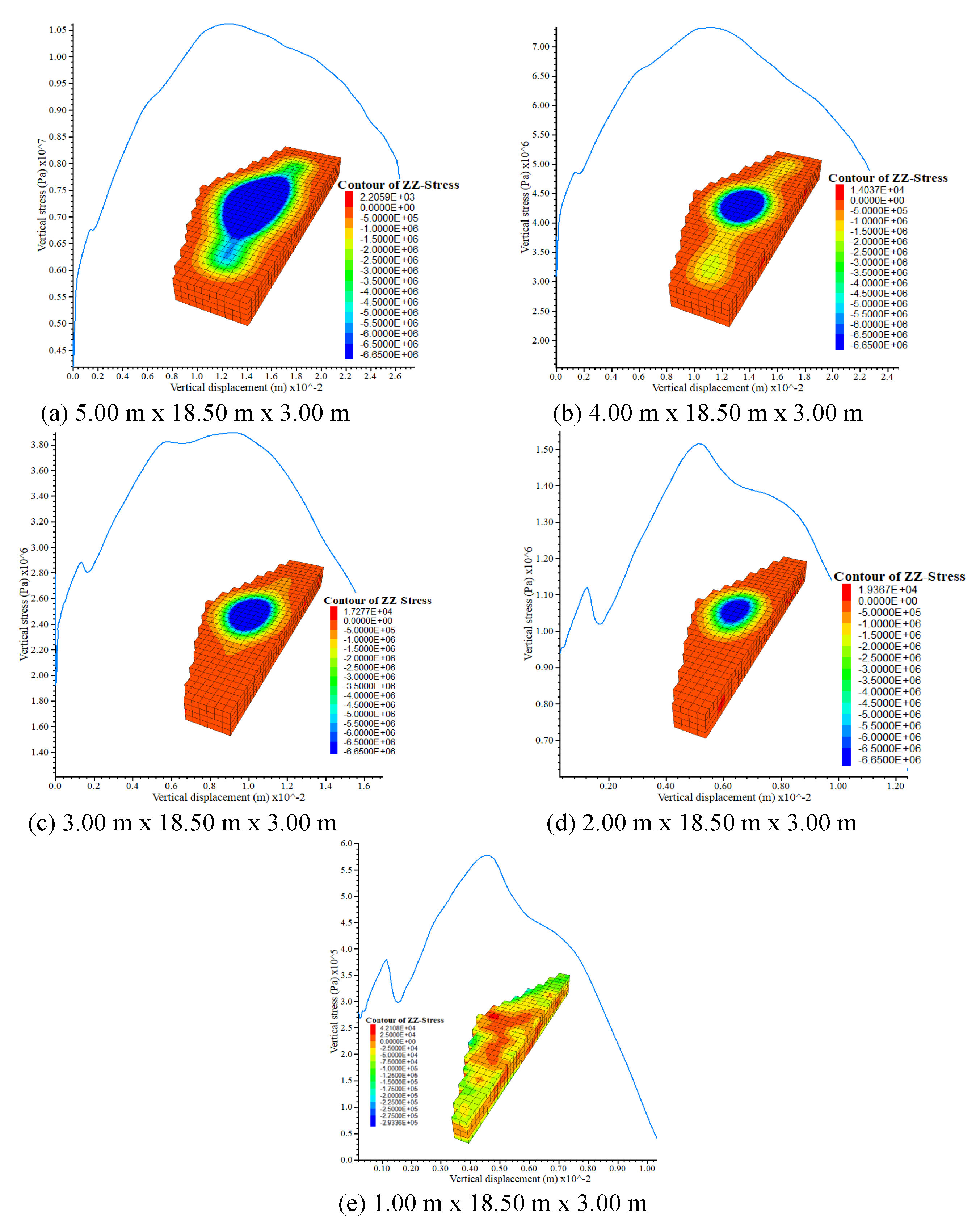
Three layers of roof, coal, and floor are considered for the simulation as the strength of rib/snook has been found to be independent of the nature of the roof. The inputs for the rock mass properties of roof, floor, and coal are mentioned in
Table 6. Different sizes of the rib/snook varied during the simulation, as the manner of pillar extraction is shown in
Figure 10. The variation in the strength of different sizes of rib/snook simulated in numerical models for the panel is shown in
Figure 18. The depth and progress of extraction of coal pillar induce fractured zones in the rib/snook due to standing goaf, resulting in a decrease in their strength. Therefore, the numerical simulation strength of rib/snook formed during pillar extraction is found to be different from the empirical formula strength. The strength estimated using simulation studies is found to be useful in estimating their FOS. Kumar [
2,
3] found that a limiting FOS of rib/snook of 0.30–0.35 is sufficient for temporary support during the slicing operation. Furthermore, such rib/snook fail in a controlled manner without inhibiting roof fall. Here, rib/snook size of 3.00 m × 18.50 m × 3.00 m (area of 81.60 m
2, equivalent width of 7.62 m, and width-to-height ratio of 4.23) is proposed to be left during MD operation, which may be further reduced up to 2.00 m × 18.50 m × 3.00 m (area of 71.60 m
2, equivalent width of 6.86 m, and width-to-height ratio of 3.81) due to side spalling of pillars based on limiting FOS of 0.30–0.35.
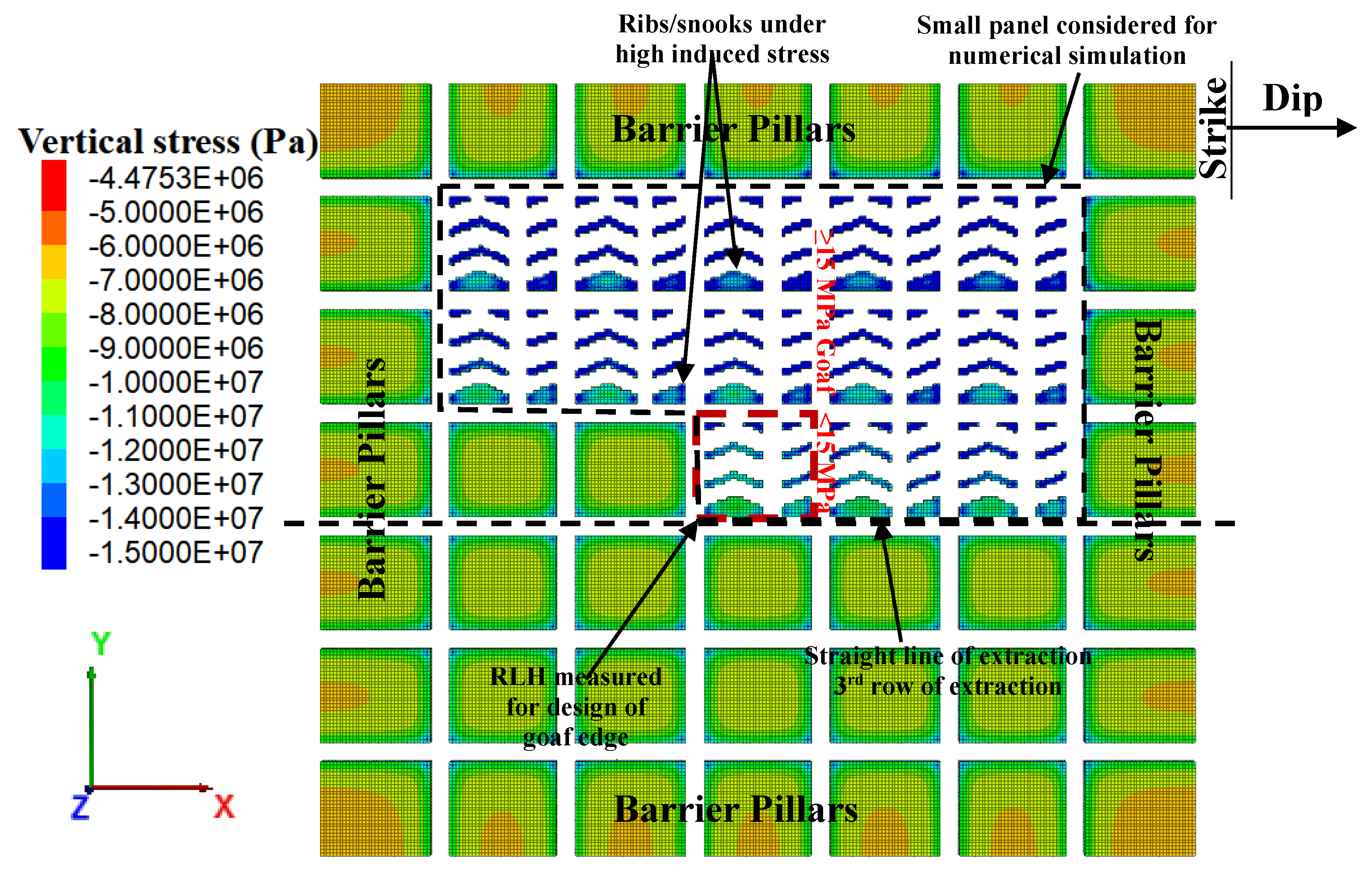
4.1.2. Simulation for Estimation of RLH at Different Places in the Panel
The geometry of the generated model is 229.5 m, 271 m, and 102 m along the length (x-axis), width (y-axis), and height (z-axis), respectively, including 50 m floor (
Figure 19), considering the hardware constraint (memory and runtime) of a computer. This model is incorporated with the existing geo-mining conditions and rock mass properties. The thickness of the coal seam considered in the model is 1.8 m, developed and depillared to full height. A truncated load (0.025 MPa/m × 214 m) is applied over the top of the model for the left-out unmodelled roof of 216 m. The width of original/split galleries is kept at 5.5 m, respectively. The bottom and four side walls of the model are fixed, while the top one is kept free as boundary conditions. The properties of rock mass used in the models are collected from the mines and tested in the laboratory, as mentioned in
Table 7. Initially, the in situ model is developed as per the abovementioned geometry at a depth of 266 m, followed by the development of pillars and galleries, as per BPMM. This model is then depillared following a straight line of extraction (
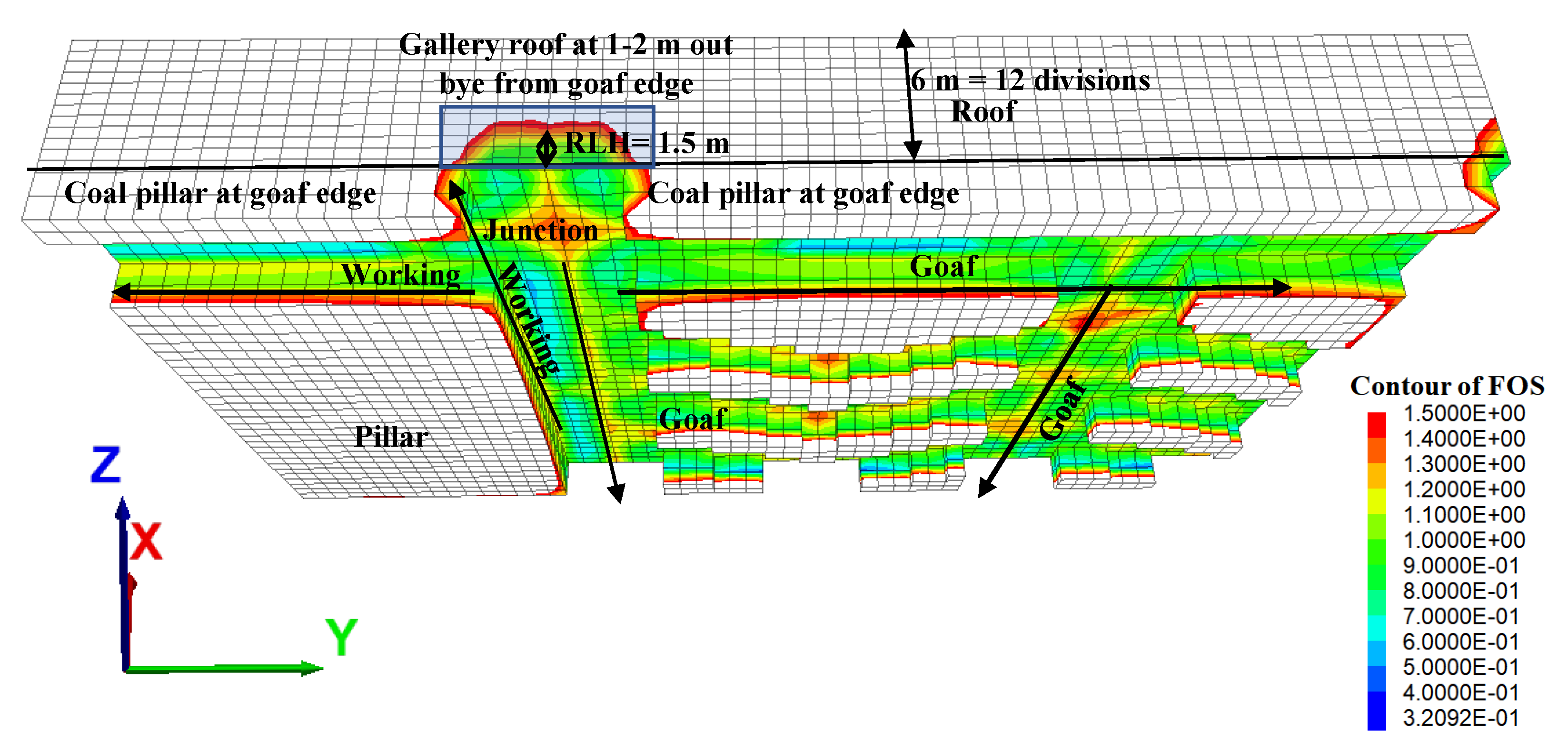
Figure 20). The height of the rock load to be supported by the roof bolt is estimated for the development and depillaring operation. Here, RLH is defined as the height of the roof strata up to the safety factor contour value of 1.0 in the model, which needs artificial support. RLH is measured at different locations, which is shown in
Figure 20 and
Figure 21. Support design for the panel on the basis of numerical modeling study is given in
Figure 9. RLH is measured at a distance of 1.0 m outby from the goaf edge (
Figure 21) without using applied support in the model, which is found to be 1.5 m (3.75 t/m
2). SSF of the proposed support plan at the goaf edge is found to be 2.50 for an applied support resistance of 67.87 t/m
2, considering the dynamic effects at the goaf edge.
5. Strata Control by Roof Blasting
The caving characteristics of the overlying strata of the goaf are one of the important parameters that influence the abutment loading in and around the working face and along the line of extraction. Difficulty in caving leads to the built-up of induced stresses, leading to fracturing in natural support present in and around the working face and sometimes goaf encroachment. The Cavability Index determines the difficult-to-easy level of fall of overlying strata [
16] and the key strata exhibit the load transfer mechanism toward the working area. Generally, the caving nature is assessed through the Cavability Index of overlying strata of around 10–15 times of working height. In the case of easily to moderately cavable roof strata (I ≤ 5000), generally, roof blasting for inducing caving is not required as experienced in Pinoura Colliery and Anjan Hills Mine of SECL [
2]. However, overlying strata that are cavable with difficulty (
5000), need design of roof drilling and blasting to induce roof fall inside the goaf. Roof blasting induces/develops fractures in the roof rock mass, which causes the hanging roof to cave. Roof blasting for difficult-to-cave overlying strata is advantageous from a ground control point of view. However, there are some associated blasting issues of ground vibration and toxic gases that affect working conditions. The Tawa-I mine has a degree 2 gassiness (explosion chances for degree 3 gassiness); therefore, roof blasting to induce caving is to be performed with extra precautions.
Design of Roof Blasting for Inducing Caving
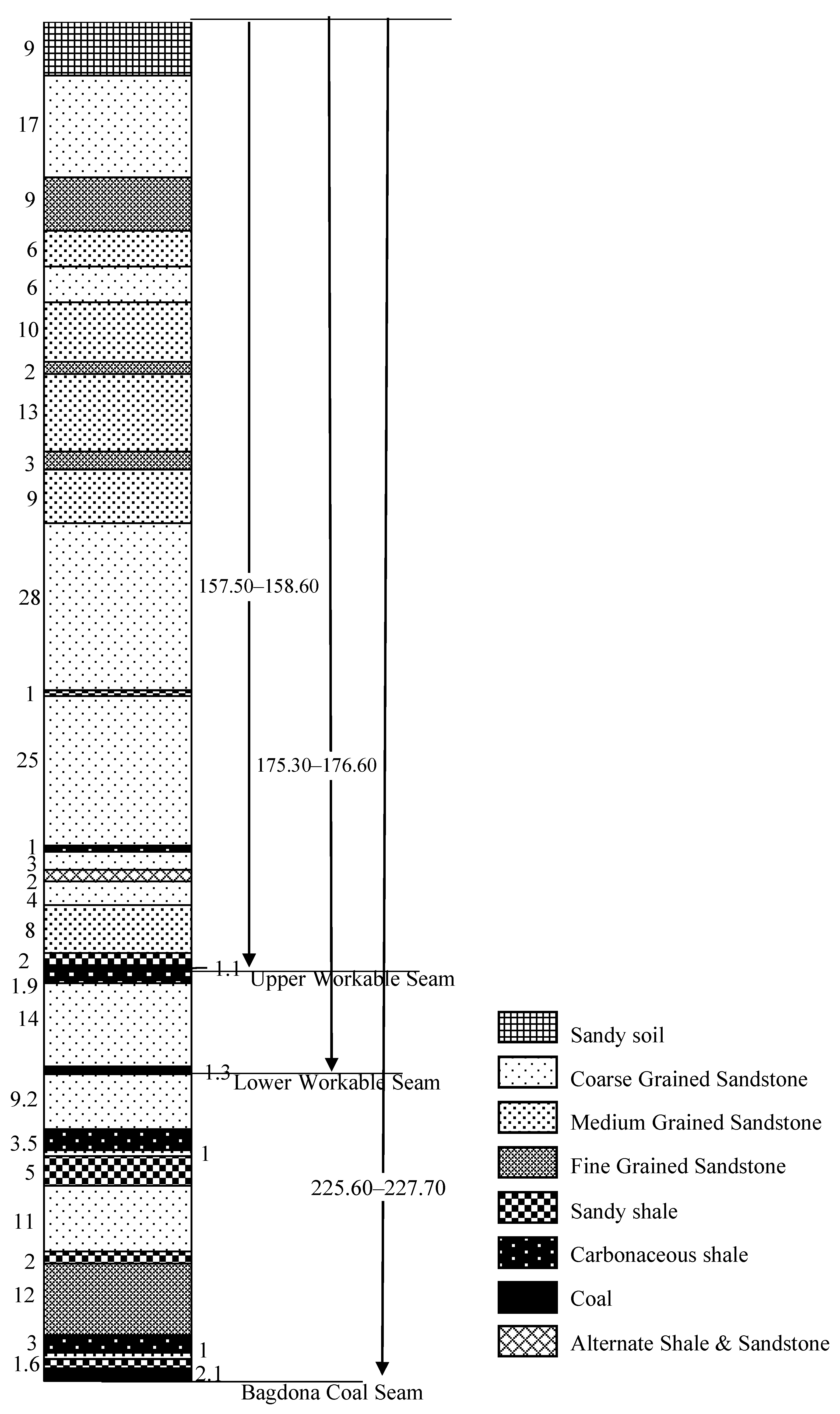
Borehole CMPS 22 (
Figure 2) is considered for the design of roof blasting to induce caving inside the goaf. Considering 10% of the bulking factor, the height of the caving (18 m) will be 10 times the height of the extraction (1.8 m). The overlying strata mostly contain 12 m of fine-grained sandstone, 1–2 m medium-grained sandstone, and 2–3 m of shale/carbonaceous shale. The average core recovery is more than 92%, and RQD is also well above 90. The Cavability Index of overlying strata of around 10 times the working height, is found to be between 7000 and 8000, which is categorized as roof cavable with difficulty in nature, and requires induced caving by the blasting of the roof in case of overhang. The fine-grained sandstone of 12 m in the roof will delay the caving of the roof in the goaf due to its massiveness of 12 m and a uniaxial compressive strength (40 MPa). It will also cause the development of higher induced stress along the line of extraction at around 8700 m
2 cumulative area of goaf. It is required to blast this roof horizon to induce caving for regular roof fall. Furthermore, it is reported [
38] that the nature of the immediate roof strata up to 20 m plays a significant role till the caving starts. It explained the process of cantilevering after the first roof fall (break of the beam) and further collapse of the hanging cantilever of the roof strata with the progress of the extraction.
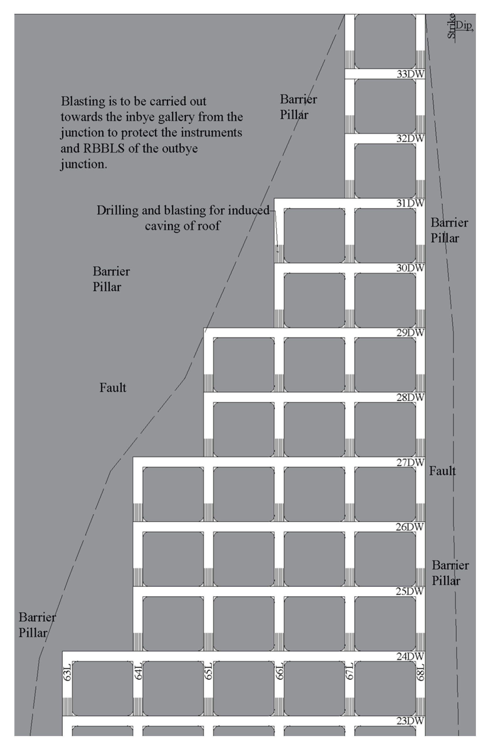
Considering the geo-mining conditions of the panel, roof blasting of up to 9 m thickness includes 2 m shale, 1 m medium-grained sandstone, 3 m carbonaceous shale, and 3 m of fine-grained sandstone roof horizon, which is required to induce fracturing in the rock mass to facilitate regular caving. Roof blasting may be conducted around the junction toward the barrier pillar right from the start of pillar extraction, as shown in
Figure 22. In order to induce fractures in the roof horizon, a vertical blast hole of up to 9 m of 42 mm diameter is to be drilled toward the inby of the junction in the goaf to avoid any sort of damage to RBBLS and instruments installed at junctions, as shown in
Figure 23. Details of the drilling pattern and explosive charging are shown in
Figure 24 and
Table 8. Six blast holes should be drilled in a row at a distance of 0.25 m from the adjacent edge of the pillar and at a distance of 1.0 m from each other. Additionally, they should be directed toward the inby of the junction in the goaf to ensure the efficacy of RBBLS and remote observations of instrument readings. Drilling and charging at the junctions should be completed before they shift into goaf. The blast hole is to be charged with a 32 mm diameter of explosive cartridge and a 6 mm detonating cord together, using plastic spacer pipes of 40 mm outer diameter, 38 mm inner diameter, and 6 m in length. The proposed method of charging blast holes is given in
Figure 25.
6. Instrumentation and Monitoring
Strata behavior during the proposed mechanized depillaring of the panel needs to be studied through field instrumentation and monitoring. The purpose of the field instrumentation is to enhance the safety of the working to protect men and machinery from any risk and also to increase the production and productivity of the mine along with verification of the design of different structures involved. It may provide some quantitative values of strata movement and concentration of induced stresses in and around the workings for a better understanding of the rock mass behavior and further, in optimization of the design.
It is important to study roof sagging in galleries, with special attention to the junctions using roof extensometers. It is always good to opt for a simple approach to instrumentation and monitoring. However, attention is to be paid to the selection of durable and robust instruments, suitable for the underground coal mining environment. Attempts are made to monitor the readings of the instruments nearly continuously in time. The density of the instruments at the studied sites is optimized through available experiences of such monitoring. A preliminary instrumentation plan for monitoring the performance of underground structures in panels is shown in 26, respectively. This plan may be modified on the extent of development possible, the geological discontinuities unraveled, strata control experiences during work in the panel at different stages, and the selection of pillars extracted from the panel.
It should be noted here that extra caution is needed while correctly installing the different geotechnical instruments before commencement of MD operation. An attempt is to be made to monitor the readings of the instrument installed in the active mining zone (AMZ) frequently. Actions to be taken during depillaring operation on the basis of roof displacement are shown in
Table 9. Details of the instruments proposed to be used for strata control monitoring in these panels are mentioned in
Figure 26. Considering the panel for CM-based mechanized depillaring at this mine, extra caution has been taken to maintain safety during pillar extraction by the installation of a series of geotechnical instruments at suitable locations and comprehensive monitoring.
The main roof fall is expected to occur at an average roof span of around 8700 m2 in the goaf. Since the width of the panel is not sufficient during the first five rows (33DW-29DW), the, first main roof fall would not occur until working in 29DW. It is expected that the main roof fall will take place during or after extraction in 28DW. Considering the anticipated large roof span (>10,000 m2) in the goaf before the main fall and the uncertain behavior of roof rock, instruments (stress meters, rib extensometers, and 6-gauge instrumented roof bolts) have been proposed frequently after 28DW for early indication of the first main fall in the panel. If the fall occurred as expected while working in 28DW, then the proposed instrumentation plan needs to be modified for 27DW. However, if the fall occurs while working either in 27DW or 26DW then the proposed instrumentation plan needs no modification. Further, the number of instruments may be optimized based on the observations of strata behavior at different stages of working in the panel.
7. Conclusions and Recommendations
Mechanized depillaring with continuous miner technology has proven its effectiveness in Indian coalfields by improving strata control management, primarily due to the faster extraction rate. An attempt has been made in this paper to predict the safe design of underground structures involved for better strata control while working with Continuous Miner Technology based on available empirical and numerical simulation studies. A numerical modeling study helped in fixing the gallery width to 5.5. m and COD of 11 m, considering 5 mm as the permissible limiting value of roof sagging to induce permanent movement (plastic/loose in nature) in the split/original galleries to be driven. A stress–strain curve was observed on the numerical models to estimate an optimum size of rib/snook such that it fails in a controlled manner without inhibiting roof falls after the completion of the slicing operation. Here, a rib/snook size of 3.00 m × 18.50 m × 3.00 m (area of 81.60 m2, equivalent width of 7.62 m, and width-to-height ratio of 4.23) was proposed to be left during MD operation, which was further reduced up to 2.00 m × 18.50 m × 3.00 m (area of 71.60 m2, equivalent width of 6.86 m, and width-to-height ratio of 3.81) due to side spalling of pillars based on permissible limiting FOS of 0.30–0.35. It was found to be matching with the values estimated using empirical formulations. RLH was measured at different locations for the design of breaker-line support in the numerical model at a distance of 1.0 m outby from the goaf edge without using applied supports in the model, which was found to be 1.5 m (3.75 t/m2). The SSF of the proposed support plan at the goaf edge was found to be 2.50 for an applied support resistance of 67.87 t/m2, and considering the dynamic effects at the goaf edge, it was found to be matching with the values estimated using empirical formulations. An empirical study estimated an average hanging roof span of 32 m (around 8700 m2 for a panel width of 271 m) was found to be inducing the first major fall of the beam roof to form a cantilever. Furthermore, a roof span of around 21 m (around 5687 m2 for a panel width of 271 m) was found to be causing the subsequent goafing and caving of the cantilever. However, roof falls will not take place during the initial five rows of pillar extraction, even with a roof span of 8700 m2 or more, due to insufficient panel width of one/two pillars. The first main roof fall was expected to occur during or before the extraction of the pillar in the eighth row. The Cavability Index of overlying strata of around 10 times the working height was found to be between 7000 and 8000. This categorized the roof as cavable with difficulty in nature and required induced caving by the blasting of the roof to avoid overhang. Fine-grained sandstone, measuring 12 m in the roof, was expected to delay the caving of the roof in the goaf due to its massiveness of 12 m and uniaxial compressive strength (40 MPa). Roof blasting of up to 9 m in the roof horizon, which includes 2 m of shale, 1 m of medium-grained sandstone, 3 m of carbonaceous shale, and 3 m of fine-grained sandstone roof horizon, was required to be conducted to induce fracturing in the rock mass to facilitate regular caving. In order to induce fractures in the roof horizon, a vertical blast hole up to 9 m of 42 mm diameter was required to be drilled toward the inby of the junction in the goaf to avoid any sort of damage to RBBLS and instruments installed at junctions. Six blast holes were required to be drilled in a row, at a distance of 0.25 m from the adjacent edge of the pillar and at a distance of 1.0 m from each other toward the inby of the junction in the goaf to ensure the efficacy of RBBLS and remote observations of reading of instruments. Drilling and charging at the junctions were required to be completed before their shifting into goaf with the progress of pillar extraction. The blast holes were required to be charged with a 32 mm diameter of explosive cartridge and a 6 mm detonating cord together using plastic spacer pipes of 40 mm outer diameter, 38 mm inner diameter, and 6 m in length. Furthermore, the instrumentation plan proposed will be used to verify the design of roof blasting and the competence of different geotechnical structures involved. This study will prove to be helpful for mining professionals/academicians to plan safe and efficient pillar extraction using the continuous technology in Indian underground coal mines.
Author Contributions
Conceptualization, A.G.; methodology, A.G.; formal analysis, A.G., A.K. and S.R.; investigation, A.G.; resources, A.G., A.K. and S.R.; writing—original draft preparation, A.G., A.K. and S.R.; writing—review and editing, A.G., A.K., S.R., K.S., K.Z., A.Z., K.M. and M.M.; visualization, A.G., A.K. and S.R.; supervision, A.G., A.K., S.R., K.S., K.Z., A.Z., K.M. and M.M.; project administration, A.G., A.K., S.R., K.S., K.Z., A.Z., K.M. and M.M.; funding acquisition, A.G., A.K., S.R., K.S., K.Z., A.Z., K.M. and M.M. All authors have read and agreed to the published version of the manuscript.
Funding
AGH University of Krakow, scientific subsidy under number: 16.16.100.215.
Institutional Review Board Statement
Not applicable.
Informed Consent Statement
Not applicable.
Data Availability Statement
The data presented in this study are available on request from the corresponding author.
Acknowledgments
The authors express their thankfulness to the Director of IIT(ISM) Dhanbad and the Director of the Institute of co-authors for their permission to publish this paper. The cooperation provided by the management of Tawa-II Mine and M/s Aurobindo Reality and Infrastructure Private Limited at different stages of the study is thankfully acknowledged. The views expressed in the paper are those of the authors and do not necessarily reflect the opinion of their respective institutes.
Conflicts of Interest
Author Abhishek Gautam was employed by the company Eastern Coalfields Limited (a Subsidiary of Coal India Limited). Author Krzysztof Migda was employed by the company Gorotech sp. z o.o. The remaining authors declare that the research was conducted in the absence of any commercial or financial relationships that could be construed as a potential conflict of interest.
References
- Kumar, A.; Kumar, D.; Singh, A.K.; Ram, S.; Kumar, R. Development of empirical model for strength estimation of irregular-shaped-heightened-rib/snook for mechanised depillaring. Int. J. Rock Mech. Min. Sci. 2021, 148, 104969. [Google Scholar] [CrossRef]
- Kumar, A. Development of Design Norms for Rib/Snook During Mechanised Depillaring by Continuous Miner. Ph.D. Thesis, Submitted to. Indian Institute of Technology (Indian School of Mines), Dhanbad, India, 2021. [Google Scholar]
- Kumar, A.; Ram, S.; Kumar, D.; Singh, A.K.; Kumar, R. Development of design norms for rib/snook during mechanised depillaring by continuous miner. Int. J. Rock Mech. Min. Sci. 2023, 161, 105259. [Google Scholar] [CrossRef]
- Ram, S.; Kumar, D.; Singh, A.K.; Kumar, A.; Singh, R. Field and numerical modelling studies for an efficient placement of roof bolts as breaker line support. Int. J. Rock Mech. Min. Sci. 2017, 93, 152–162. [Google Scholar] [CrossRef]
- Mine Safety and Health Administration (MSHA). Coal Miner’s Handbook for Roof and Rib Control; MSHA Publications: Washington, DC, USA, 2008; pp. 1–56. [Google Scholar]
- Jayanthu, S. Strata control problems of underground coal mining vis-à-vis geotechnical instrumentation and numerical model studies. In Proceedings of the International Conference on Underground Space Technology, Bangalore, India, 17–19 January 2011. [Google Scholar]
- Konicek, P.; Soucek, K.; Stas, L.; Singh, R. Long-hole destress blasting for rockburst control during deep underground coal mining. Int. J. Rock Mech. Min. Sci. 2013, 61, 141–153. [Google Scholar] [CrossRef]
- Huang, B.; Zhao, X.; Chen, S.; Liu, J. Theory and technology of controlling hard roof with hydraulic fracturing in underground mining. Chin. J. Rock Mech. Eng. 2017, 36, 2954–2970. [Google Scholar]
- Xu, T.; Yang, T.H.; Chen, C.F.; Liu, H.L.; Yu, Q.L. Mining-induced strata movement and roof behavior in underground coal mines. Geomech. Geophys. Geo-Energy Geo-Resour. 2018, 1, 79–89. [Google Scholar] [CrossRef]
- Kang, H.; Wang, G.; Jiang, P.; Wang, J.; Zhang, N.; Jing, H.; Huang, B.; Yang, B.; Guan, X.; Wang, Z. Conception for Strata Control and Intelligent Mining Technology in Deep Coal Mines with Depth More Than 1000 m. J. China Coal Soc. 2018, 43, 1789–1800. [Google Scholar]
- Guo, J.; Feng, G.; Wang, P.; Qi, T.; Zhang, X.; Yan, Y. Roof Strata Behavior and Support Resistance Determination for Ultra-Thick Longwall Top Coal Caving Panel: A Case Study of the Tashan Coal Mine. Energies 2018, 11, 1041. [Google Scholar] [CrossRef]
- Jangara, H.; Ozturk, C.A. Longwall top coal caving design for thick coal seam in very poor strength surrounding strata. Int. J. Coal Sci. Technol. 2021, 8, 641–658. [Google Scholar] [CrossRef]
- Kumar, R.; Mishra, A.K.; Kumar, A.; Singh, A.K.; Ram, S.; Singh, R. Importance of fracturing hard and massive overlying strata for complete extraction of thick coal seam- Case studies. J. Geol. Soc. India 2022, 98, 203–210. [Google Scholar] [CrossRef]
- Wang, H.; Wang, J.; He, M.; Tian, X.; Ma, Z.; Liu, P. Mechanism of roof presplitting in nonpillar coal mining technology and its reasonable parameters in hard roof and longwall top-coal caving face. Energy Explor. Exploit. 2023, 41, 696–727. [Google Scholar] [CrossRef]
- Chang, Z.; Wang, X.; Qin, D.; Yu, J.; Chen, X.; Wang, J.; Niu, Z.; Qian, C. Safety and high-recovery mechanisms and application research for initial mining of thick-coal-seam with complex structure and thick-hard roof. Sci. Rep. 2024, 14, 19638. [Google Scholar] [CrossRef] [PubMed]
- Sarkar, S.K. Mechanised Longwall Mining-The Indian Experiences; Mohan Primlani for Oxford & IBH Publishing Co. Pvt. Ltd.: New Delhi, India, 1998; pp. 27–35. [Google Scholar]
- Sheorey, P.R. Pillar Strength Considering In Situ Stresses; Information Circular (IC) 9315; United States Department of the Interior, Bureau of Mines: Washington, DC, USA, 1992; pp. 122–127. [Google Scholar]
- Bieniawski, Z.T. The design process in rock engineering. Rock Mech Rock Eng. 1984, 17, 183–190. [Google Scholar] [CrossRef]
- Bieniawski, Z.T. Classification of rock masses for engineering: The RMR system and future trends. In Comprehensive Rock Engineering; Hudson, J.A., Ed.; Pergamon Press: New York, NY, USA, 1993; Volume 3, pp. 553–573. [Google Scholar]
- Bieniawski, Z.T. Engineering Rock Mass Classifications; Wiley: New York, NY, USA, 1989. [Google Scholar]
- Bieniawski, Z.T. Rock mass classifications in rock engineering. In Proceedings of the Symposium on Exploration for Rock Engineering, Rotterdam, The Netherlands, 1–5 November 1976; Volume 1, pp. 97–106. [Google Scholar]
- Molinda, G.M.; Mark, C. The Coal Mine Roof Rating (CMRR)—A practical rock mass classification for coal mines. In Proceedings of the 12th Conference on Ground Control in Mining; Peng, S.S., Ed.; West Virginia University: Morgantown, WV, USA, 1993; pp. 92–103. [Google Scholar]
- Bauer, E.R. The Impact of Extended Depth-of-Cut Mining on Coal Mine Ground Control and Worker Safety. Ph.D. Thesis, Department of Mineral Engineering, The Penn State University, University Park, PA, USA, 1998. [Google Scholar]
- Mandal, P.K.; Das, A.J.; Kumar, N.; Bhattacharjee, R.; Tewari, S.; Kushwaha, A. Assessment of roof convergence during driving roadways in underground coal mines by continuous miner. Int. J. Rock Mech. Min. Sci. 2018, 108, 169–178. [Google Scholar] [CrossRef]
- Saharan, M.R.; Jha, B.K.; Sazid, M.; Kumar, R. Designing cut out distance for continuous miners operation using numerical modelling and rock mechanics instrumentation. In Proceedings of the Workshop on Application of Rock Mechanics: Tools & Techniques, Nagpur, India, 15–17 January 2010; pp. 24–31. [Google Scholar]
- Mark, C. Application of coal mine roof rating (CMRR) to extended cuts. Min. Eng. 1999, 51, 52–56. [Google Scholar]
- Kumar, A.; Kumar, D.; Singh, A.K.; Ram, S.; Kumar, R.; Singh, A.K.; Raja, M.; Singh, R. Rock mechanics challenges and advances in continuous miner based mechanised depillaring of coal pillars. In Proceedings of the National Conference on Advances in Mining, CSIR-CIMFR, Dhanbad, India, 14–15 February 2020; pp. 32–46. [Google Scholar]
- Wilson, A.H. A hypothesis concerning pillar stability. Min. Eng. 1972, 131, 409–417. [Google Scholar]
- Gao, W. Study on the width of the non-elastic zone in inclined coal pillar for strip mining. Int. J. Rock Mech. Min. Sci. 2014, 72, 304–310. [Google Scholar]
- Suchowerska, A.M.; Merifield, R.S.; Carter, J.P. Vertical stress changes in multi-seam mining under supercritical longwall panels. Int. J. Rock Mech. Min. Sci. 2013, 61, 306–320. [Google Scholar] [CrossRef]
- Gao, W.; Ge, M. Stability of a coal pillar for strip mining based on an elastic-plastic analysis. Int. J. Rock Mech. Min. Sci. 2016, 87, 23–28. [Google Scholar] [CrossRef]
- Venkateswarlu, V.; Ghose, A.K.; Raju, N.M. Rock mass classification for design of roof support—A statistical evaluation of parameters. Min. Sci. Technol. 1989, 8, 97–107. [Google Scholar] [CrossRef]
- Van der Merwe, J.N. Fundamental analysis of the interaction between overburden behaviour and snook stability in coalmines. J. South Afr. Inst. Min. Metall. 2005, 105, 63–73. [Google Scholar]
- Palchik, V. Bulking factors and extents of caved zones in weathered overburden of shallow abandoned underground workings. Int. J. Rock Mech. Min. Sci. 2015, 79, 227–240. [Google Scholar] [CrossRef]
- Sheorey, P.R. Empirical Rock Failure Criteria; Balkema: Rotterdam, The Netherlands, 1997; p. 176. [Google Scholar]
- Sheorey, P.R. A theory of in situ stress in isotropic and transversely isotropic rocks. Int. J. Rock Mech. Min. Sci. 1994, 31, 23–34. [Google Scholar] [CrossRef]
- Kumar, A.; Kumar, D.; Singh, A.K.; Ram, S.; Kumar, R.; Gautam, A.; Singh, R.; Singh, A.K. Roof sagging limit in an early warning system for safe coal pillar extraction. Int. J. Rock Mech. Min. Sci. 2019, 123, 104131. [Google Scholar] [CrossRef]
- Anderson, I. Case Studies of Buried Continuous Miners and Fatal Pillar Extraction Accidents in New South Wales; Strata Control for Coal Mine Design, School of Mines, University of New South Wales: Sydney, NSW, Australia, 1993. [Google Scholar]
Figure 1.
Partings between different coal seams present in Tawa-I mine.
Figure 1.
Partings between different coal seams present in Tawa-I mine.
Figure 2.
Borehole lithology above the panel of Bagdona Coal Seam based on CMPS 22.
Figure 2.
Borehole lithology above the panel of Bagdona Coal Seam based on CMPS 22.
Figure 3.
Panel in Bagdona Coal Seam of Tawa-I Underground Coal Mine.
Figure 3.
Panel in Bagdona Coal Seam of Tawa-I Underground Coal Mine.
Figure 4.
(a) Widening the 3.8 m width of the gallery to 5.5 m for the adaptability of the Continuous Miner machine and (b) Extraction of 1.45 m corners of pillars around the junction for the adaptability of the 11.9 m length of the cutting machine.
Figure 4.
(a) Widening the 3.8 m width of the gallery to 5.5 m for the adaptability of the Continuous Miner machine and (b) Extraction of 1.45 m corners of pillars around the junction for the adaptability of the 11.9 m length of the cutting machine.
Figure 5.
Pillar (34 m × 29.5 m) is split into two unequal fenders.
Figure 5.
Pillar (34 m × 29.5 m) is split into two unequal fenders.
Figure 6.
Stand-up time and unsupported span based on Rock Mass Rating (RMR) and Joint factor (Jr) [
18].
Figure 6.
Stand-up time and unsupported span based on Rock Mass Rating (RMR) and Joint factor (Jr) [
18].
Figure 7.
Sequence of cutting in a gallery by continuous miner for an assumed cut-out distance of 10 m.
Figure 7.
Sequence of cutting in a gallery by continuous miner for an assumed cut-out distance of 10 m.
Figure 8.
Distribution of the vertical stress for the coal pillar in the limiting equilibrium state [
29,
30,
31].
Figure 8.
Distribution of the vertical stress for the coal pillar in the limiting equilibrium state [
29,
30,
31].
Figure 9.
Proposed support plan in the 5.5 m widened gallery of the panel.
Figure 9.
Proposed support plan in the 5.5 m widened gallery of the panel.
Figure 10.
Different sizes of rib/snook considered for the panel during extraction of pillar size of 34.0 m × 29.5 m (corner-to-corner).
Figure 10.
Different sizes of rib/snook considered for the panel during extraction of pillar size of 34.0 m × 29.5 m (corner-to-corner).
Figure 11.
Proposed manner of pillar extraction and roof bolt-based breaker line support plan in panel.
Figure 11.
Proposed manner of pillar extraction and roof bolt-based breaker line support plan in panel.
Figure 12.
A model for an overhang of length a
h supported by a snook offering resistance R at a distance a
x from the closest solid pillar [
33].
Figure 12.
A model for an overhang of length a
h supported by a snook offering resistance R at a distance a
x from the closest solid pillar [
33].
Figure 13.
Caving mechanism at the goaf edge during MD using CM [
2].
Figure 13.
Caving mechanism at the goaf edge during MD using CM [
2].
Figure 14.
Non-linearity of Sheorey criterion against the linear Mohr–Coulomb criterion adopted in the simulation package [
35].
Figure 14.
Non-linearity of Sheorey criterion against the linear Mohr–Coulomb criterion adopted in the simulation package [
35].
Figure 15.
Contour of vertical displacement for different widths driven in a gallery length of 10 m.
Figure 15.
Contour of vertical displacement for different widths driven in a gallery length of 10 m.
Figure 16.
Contour of vertical displacement for different lengths driven in a gallery width of 5 m.
Figure 16.
Contour of vertical displacement for different lengths driven in a gallery width of 5 m.
Figure 17.
Geometry of the model and boundary conditions for simulation of rib/snook.
Figure 17.
Geometry of the model and boundary conditions for simulation of rib/snook.
Figure 18.
Vertical stress-displacement characteristics of different sizes of rib/snook in the panel for a pillar size of 34.0 m × 29.5 m (corner-to-corner).
Figure 18.
Vertical stress-displacement characteristics of different sizes of rib/snook in the panel for a pillar size of 34.0 m × 29.5 m (corner-to-corner).
Figure 19.
Generated block and boundary conditions in situ model of panel.
Figure 19.
Generated block and boundary conditions in situ model of panel.
Figure 20.
Manner of pillar extraction, their sequence and locations marked for measurement of RLH in the numerical model for the design of support system at the goaf edge in panel.
Figure 20.
Manner of pillar extraction, their sequence and locations marked for measurement of RLH in the numerical model for the design of support system at the goaf edge in panel.
Figure 21.
RLH at goaf edge during mechanized depillaring of panel.
Figure 21.
RLH at goaf edge during mechanized depillaring of panel.
Figure 22.
Schematic diagram of induced caving by roof blasting during extraction of second row of pillar after completion of extraction of Pillar No. 5.
Figure 22.
Schematic diagram of induced caving by roof blasting during extraction of second row of pillar after completion of extraction of Pillar No. 5.
Figure 23.
Sectional view of the drilled hole with explosive charging pattern.
Figure 23.
Sectional view of the drilled hole with explosive charging pattern.
Figure 24.
Plan view of drilling pattern for induced caving by blasting along the drilling plane.
Figure 24.
Plan view of drilling pattern for induced caving by blasting along the drilling plane.
Figure 25.
Proposed method of charging of blast holes.
Figure 25.
Proposed method of charging of blast holes.
Figure 26.
Proposed location of different instruments to be used in the panel.
Figure 26.
Proposed location of different instruments to be used in the panel.
Table 1.
Geo-mining conditions of the panel.
Table 1.
Geo-mining conditions of the panel.
| Parameters | Panel Details |
|---|
| Name of the coal seam | Bagdona Coal Seam (BCS) |
| Boreholes in/around the panel | CMPS-2, 22 |
| Grade of coal | G-6 and G-8 |
| Degree of gassiness | II |
| Seam thickness | 1.77 m ≈ 1.8 m |
| Gradient of seam | 1 in 20 along level and 1 in 16 along dip |
| Status of overlying and underlying coal seams | Overlying LWS at a parting of 50 m has been extracted by the caving method |
| Overlying structures | Rainy Season Nalla |
| Roof | 1.6 m—sandy shale, 1 m—medium-gained sandstone, 3 m—carbonaceous shale, 12 m—fine-grained sandstone |
| Immediate roof | 1.6 m—Sandy shale |
| Immediate floor | Sandy shale with thin sandstone |
| Geological Disturbance | Within the Panel- Local faults with a throw of 1.6 m, slips, cracks
Rise Side of Panel- Fault F7B with a throw of 10–20 m
Dip Side of Panel- Fault F7A with a throw of 28 m |
| Panel extent | From 63L to 69L and 6D to 33D between faults F7A (upthrow 30 m) and F7B (downthrow 30 m) |
| Size of pillar | 39.5 m × 35 m (center to center), 35.7 m × 31.2 m (corner-to-corner) during development by drilling-blasting with 3.8 m gallery width |
| Number of pillars | 114 (may change depending upon slips and faults exposed during the development of the virgin area in the panel) |
| Panel length | 27 pillars (27 × 35 + 4= 949 m) |
| Panel width | Maximum 5 pillars (39.5 × 5 + 4 = 201.5 m) but vary from 1 to 5 pillars |
| Extraction height | 1.80 m |
| Present width of the gallery by drilling-blasting | 3.8 m during development by drilling-blasting |
| Depth cover | 190 m to 266 m |
| RMR of seam | 50.4 |
| Compressive strength of coal | 23 MPa (as per NIRM report November 2012) |
| Existing Support during development by drilling and blasting | Quick setting cement grouted roof bolts at 1.2 m × 0.8 m grid pattern |
| Incubation Period | 24 months |
| Boundary | North | Mine boundary |
| South | Panel No. W7 and W7 X-Cut |
| East | Panel No. E8 |
| West | Shobhapur abandoned coal mine |
| Existing support system | Quick setting cement grouted roof bolts at 1.2 m × 0.8 m grid pattern |
| Waterlogging and fire | Free from waterlogging and fire |
Table 2.
Caving index versus caving nature of strata [
16].
Table 2.
Caving index versus caving nature of strata [
16].
| Classification of Roof | Cavability Index | Remarks |
|---|
| Easily cavable roof | I ≤ 2000 | No perceptible weighting on the face |
| Moderately cavable roof | 2000 < I ≤ 5000 | Weighting but not dynamic in nature |
| Roof cavable with difficulty | 5000 < I ≤ 10,000 | Weighting may or may not be dynamic in nature |
| Cavable with substantial difficulty | 10,000 < I ≤ 14,000 | Weighting may or may not be dynamic in nature |
| Cavable with extreme difficulty | I ≥ 14,000 | Weighting will be dynamic in nature |
Table 3.
Safety factors of the developed pillars by drilling and blasting and reduced pillars by widening of galleries by Continuous Miner and fenders after their splitting.
Table 3.
Safety factors of the developed pillars by drilling and blasting and reduced pillars by widening of galleries by Continuous Miner and fenders after their splitting.
| Method | Structure | H
(m) | W1
(m) | W2
(m) | We
(m) | B
(m) | h
(m) | σc
(MPa) | Strength (MPa) | Load (MPa) | Safety Factor |
|---|
| Drilling and Blasting | Pillar | 266 | 35.7 | 31.2 | 33.30 | 3.8 | 1.8 | 23 | 41.14 | 8.25 | 4.98 |
| CM | Pillar | 266 | 34 | 29.5 | 31.60 | 5.5 | 1.8 | 23 | 39.19 | 9.17 | 4.28 |
| Fender-I | 10 | 29.5 | 14.9 | 5.5 | 20.09 | 12.23 | 1.64 |
| Fender-II | 18.5 | 29.5 | 22.7 | 5.5 | 29.04 | 10.24 | 2.84 |
Table 4.
Support design for developed panel.
Table 4.
Support design for developed panel.
| Place | Parameters | Development by Drilling and Blasting | Development by Continuous Miner |
|---|
| Gallery | Width (m) | 3.80 | 5.50 |
| Dry density of rock (t/m3) | 2.51 | 2.51 |
| Rock Mass Rating | 50.40 | 50.40 |
| Anchorage strength of resin--grouted roof bolts (t) | 10.00 | 20.00 |
| Rock load (t/m2) | 3.27 | 4.74 |
| Spacing between two bolts in a row (m) | 1.20 | 1.10 |
| Spacing between two consecutive rows of bolts (m) | 0.80 | 1.10 |
| Number of roof bolts in a row | 3 | 5 |
| Area supported by one row of bolts (m2) | 4.56 | 6.05 |
| Support resistance (t/m2) | 6.58 | 16.53 |
| Support safety factor | 2.01 | 3.49 |
| Junction | Rock load (t/m2) | 4.91 | 7.11 |
| Area supported by all bolts (m2) | 14.44 | 30.25 |
| Number of roof bolts | 11 | 33 |
| Support resistance (t/m2) | 7.62 | 21.82 |
| Support safety factor | 1.55 | 3.07 |
Table 5.
Strength of different sizes of rib/snook in the panel.
Table 5.
Strength of different sizes of rib/snook in the panel.
| Size of Rib/Snook | Area (m2) | Perimeter (m) | Equivalent Width (m) | Width-to-Height Ratio | Strength (MPa) |
|---|
| 5.00 m × 18.50 m × 3.00 m | 101.60 | 46.84 | 8.68 | 4.82 | 10.57 |
| 4.00 m × 18.50 m × 3.00 m | 91.60 | 44.84 | 8.17 | 4.54 | 10.21 |
| 3.00 m × 18.50 m × 3.00 m | 81.60 | 42.84 | 7.62 | 4.23 | 9.81 |
| 2.00 m × 18.50 m × 3.00 m | 71.60 | 41.75 | 6.86 | 3.81 | 9.23 |
| 1.00 m × 18.50 m × 3.00 m | 61.60 | 41.75 | 5.90 | 3.28 | 8.46 |
Table 6.
Physico-mechanical properties of strata used in numerical modeling.
Table 6.
Physico-mechanical properties of strata used in numerical modeling.
| Strata | Thickness (m) | Model | Young’s Modulus (GPa) | Shear Modulus (GPa) | Bulk Modulus (GPa) | Poisson’s Ratio | Density (kg/m3) | Cohesion (MPa) | Friction Angle | Uniaxial Compressive Strength (MPa) | Tensile Strength (MPa) |
|---|
| Layer 3: Roof | 50 | Elastic | 7 | 2.8 | 4.67 | 0.25 | 2500 | 2.43 | - | - | - |
| Layer 2: Coal | 1.8 (BCS) | MCSS | 3.00 | 1.20 | 2.00 | 0.25 | 1400 | 0.181 | 39.59 | 25 | 1.67 |
| Layer 1: Floor | 50 | Elastic | 7 | 2.8 | 4.67 | 0.25 | 2310 | - | - | - | - |
Table 7.
Constitutive model selection and physico-mechanical properties of strata used in numerical modeling of panel.
Table 7.
Constitutive model selection and physico-mechanical properties of strata used in numerical modeling of panel.
| Strata | Constitutive Model | Thickness (m) | Young’s Modulus (GPa) | Shear Modulus (GPa) | Bulk Modulus (GPa) | Poisson’s Ratio | Density | RMR for FOS | Compressive Strength (MPa) | Tensile Strength (MPa) |
|---|
| Layer 1: Floor (FGSST) | Elastic | 50.0 | 7.00 | 2.80 | 4.67 | 0.25 | 2500 | 50.40 | 50.00 | 5.00 |
| Layer 2: Coal | Elastic | 1.8 | 2.00 | 0.80 | 1.34 | 0.25 | 1400 | 50.40 | 23.00 | 2.30 |
Layer 3:
Roof, Shale | Elastic | 2.0 | 2.50 | 1.00 | 1.67 | 0.25 | 1800 | 50.40 | 30.00 | 3.00 |
| Layer 4: MGSST | Elastic | 1.0 | 5.00 | 2.00 | 3.33 | 0.25 | 2200 | 50.40 | 40.00 | 4.00 |
| Layer 5: Carbonaceous shale | Elastic | 3.0 | 2.50 | 1.00 | 1.67 | 0.25 | 1800 | 50.40 | 30.00 | 3.00 |
| Layer 6: Roof (FGSST) | Elastic | 12.0 | 7.00 | 2.80 | 4.67 | 0.25 | 2500 | 50.40 | 50.00 | 5.00 |
| Layer 6: Roof (MGSST) | Elastic | 32.0 | 5.00 | 2.00 | 3.33 | 0.25 | 2200 | 50.40 | 40.00 | 4.00 |
Table 8.
Proposed blast design parameters for induced caving.
Table 8.
Proposed blast design parameters for induced caving.
| Blast Design Parameters | Value |
|---|
| Diameter of blast hole | 42 mm |
| Number of holes per ring in a single blast | 6 |
| Depth of hole | 9.0 m |
| Spacing between holes in a row | 1.0 m |
| Distance from the side of the pillar | 0.25 m |
| Explosive charge length | 6 m |
| The diameter of each emulsion permitted cartridge | 32 mm |
| Length of each permitted emulsion cartridge | 200 mm |
| Number of cartridges in one hole of 6 m length | 30 |
| Explosive charge per hole | 6 kg |
| Total explosive charge per ring | 36 kg |
Table 9.
Actions to be taken during depillaring operation.
Table 9.
Actions to be taken during depillaring operation.
| Sl. No. | Convergence Observation | Action to Be Taken |
|---|
| 1 | up to 5 mm | No action required, monitoring should be continued but must inform to Strata Control Officer and discussed. |
| 2 | 5–10 mm | Inform the Strata Control Officer, Supervisor, and Manager special attention at the observed location. |
| 3 | 10–15 mm | If sudden increase
Stop development work, assess conditions, and install additional support in the said zone by 1.7 m length resin grouted bolts with a ‘W’ strap.
Flexi bolts of 1.7 m length should be installed |
| 4 | >15 mm | Immediately inform the Strata Control Officer, Supervisor, and Manager.
Stop development work and withdraw the machine to the outby side of the work place.
Additional supports to be installed in the gallery based on the consultation of the mine manager with the scientific institute in the said zone.
All workmen and machines shall be withdrawn to a safe place within the gallery, and no work related to production shall be allowed. |
| Disclaimer/Publisher’s Note: The statements, opinions and data contained in all publications are solely those of the individual author(s) and contributor(s) and not of MDPI and/or the editor(s). MDPI and/or the editor(s) disclaim responsibility for any injury to people or property resulting from any ideas, methods, instructions or products referred to in the content. |
© 2025 by the authors. Licensee MDPI, Basel, Switzerland. This article is an open access article distributed under the terms and conditions of the Creative Commons Attribution (CC BY) license (https://creativecommons.org/licenses/by/4.0/).


 ,
, 


