Abstract
Reductions in the vibration of a continuum system via a nonlinear energy sink have been widely investigated. It is usually assumed that weight effects can be ignored if the vibration is measured from the static equilibrium configuration. The present investigation reveals the dynamic effects of weight on the vertical transverse vibrations of a Euler–Bernoulli beam coupled with a nonlinear energy sink. The governing equations considering and neglecting weights were derived. The equations were discretized with some numerical support. The discretized equations were analytically solved via the harmonic balance method. The harmonic balance solutions were compared with the numerical solution via the Runge–Kutta method. Finite element simulations were performed via ANSYS software (version number: 2.2.1). Free and forced vibrations, predicted by equations considering or neglecting the weights, were compared with the finite element solutions. For the forced vibrations, the amplitude–frequency responses determined by the harmonic balance method agree well with those calculated by the Runge–Kutta method. The free and forced vibration responses predicted by the equations considering the weights are closer to those computed by the finite element method than the responses predicted by the equation neglecting the weights. The assumption that weights can be balanced by static deflections leads to errors in the analysis of the vertical transverse vibrations of a Euler–Bernoulli beam with a nonlinear energy sink.
1. Introduction
Nonlinear energy sinks, as a promising vibration reduction approach, have been widely applied to various beams [1,2]. The vibration of a continuum exhibits multiple vibration peaks over a wide frequency range. A nonlinear energy sink, a nonlinear absorber without linear stiffness, can adaptively reduce the resonant response of the continuum at each frequency within a wide frequency band, without introducing new resonant frequencies. When beams are modeled as continuous systems, the Galerkin method projects infinite-dimensional equations, arising from the continuous system, into a finite-dimensional subspace; therefore, the Galerkin method is usually used to truncate continuous systems into discrete systems. Therefore, response time histories and amplitude–frequency response curves can be numerically calculated. There have been some interesting numerical investigations into the vibrations of beams attached to nonlinear energy sinks.
Kani et al. optimized the parameters of nonlinear energy sinks placed on linear beams with different supports by computing the portion of the input energy dissipated by the nonlinear energy sinks [3]. Zhang et al. investigated the vibration reduction effectiveness of a nonlinear energy sink attached to an axially moving beam [4]. Zhang et al. also considered the vibration reduction effectiveness of nonlinear energy sinks for an axially moving beam under thermal shock [5]. Chen et al. numerically investigated the impact of variable stiffness and the thermal effect on the vibration absorption efficiency of nonlinear energy sinks attached to a simply supported beam [6]. Chang et al. investigated the vibration control of a cantilever beam under various parameters of a nonlinear energy sink [7]. Zhang et al. examined the effectiveness of parallel nonlinear energy sinks in suppressing the vibration of an axially moving beam induced by an impulse for different locations of the nonlinear energy sinks [8]. Li et al. conceptually proposed a symmetric single-sided vibro-impact nonlinear energy sink to suppress the transient vibration of a cantilever beam [9]. Fang et al. conceptually proposed a tuned bistable nonlinear energy sink for a hinged–hinged beam to reduce its vibration [10]. He et al. conceptually combined an acoustic black hole with a nonlinear energy sink to reduce the vibration of a nonlinear cantilevered beam, and the reduction effectiveness was numerically demonstrated by the portion of the input energy dissipated by the nonlinear energy sink [11]. Zhang et al. investigated the effectiveness of a parallel nonlinear energy sink attached to an axially moving beam under different axial speeds [12]. Xu et al. investigated a nonlinear energy sink with an electromagnetic energy harvesting mechanism and installed it on a cantilever beam for vibration reduction [13]. In the above-mentioned applications of the Galerkin truncation, the retained truncation term numbers were 1 [13], 2 [4,5,6,8,9,12], 4 [7], 6 [3], and 10 [11], respectively. Based on the applications of the Galerkin truncation, the response time histories [3,4,5,6,7,8,9,10,11,12,13] and the amplitude–frequency response curves [4,6,7,9,10] were yielded numerically.
In addition to the above-mentioned numerical investigations [3,4,5,6,7,8,9,10,11,12,13], analytical approaches can be applied to approximately determine the steady-state periodical responses of harmonically excited beams with nonlinear energy sinks [14,15,16,17,18,19,20,21,22,23,24,25,26,27,28,29,30]. Based on a complexification averaging method, Dou et al. proposed an eddy-current-damping-enhanced nonlinear energy sink that could generate damping force through the interaction between the eddy current magnetic field passing through the magnetic field and the original magnetic field, in order to control the vibration of a cantilever beam [14]. Parseh et al. optimized the parameters of a nonlinear energy sink to reduce the vibrations of a Euler–Bernoulli beam and a Timoshenko beam [15], and Chen et al. investigated single and parallel nonlinear energy sinks to suppress the vibration of a simply supported beam [16]. In particular, the method of harmonic balance has been widely applied in the design and analysis of nonlinear energy sinks [17,18,19,20,21,22,23,24,25], detailed as follows. Zhang et al. revealed the effects of the moisture and temperature environment on the vibration of a laminated composite beam with a nonlinear energy sink [17]. Moslemi et al. investigated the stability of an axially moving beam with a nonlinear energy sink [18]. Zang et al. proposed a lever-like design to enhance the reduction in the vibration of nonlinear energy sinks attached to a viscoelastic beam [19]. Zhang et al. replaced the mass in a nonlinear energy sink with an inerter to reduce its weight with the same inertia, to propose an inertial nonlinear energy sink for an elastic beam [20]. Zhang et al. further investigated the vibration of a geometrically nonlinear beam with a boundary inertial nonlinear energy sink [21]. Zhang et al. designed multiple parallel nonlinear energy sinks for the vibration suppression of a Timoshenko beam [22]. Zhang et al. applied an inertial nonlinear energy sink to suppress the vibration of an asymmetric elastically supported beam [23]. Zhao et al. analyzed the vibration of a generally restrained pre-pressure beam with multiple nonlinear energy sinks [24]. Ye et al. analyzed the vibration of a slightly curved beam with a nonlinear energy sink at the end of the beam [25]. As a variation of the method of harmonic balance, the method of incremental harmonic balance has also been applied. Based on this method, Li et al. proposed a criterion for the parametric design of bistable nonlinear energy sinks attached to beams and plates [26]. Karličić et al. developed a semi-numerical analysis for an axially moving beam with a nonlinear energy sink and a piezoelectric attachment [27]. Wang et al. investigated the influence of the natural frequency ratio of the beam and cable on the effect of a nonlinear energy sink [28]. Wang et al. discussed the effectiveness of a nonlinear energy sink with various parameters attached to a cable-stayed beam [29]. Ma et al. optimized the parameters of a nonlinear energy sink for reducing the vibration of a beam on a modified Winkler foundation [30]. In harmonic balance analysis, the harmonics order is an essential aspect. Actually, the above-mentioned works involving the harmonic balance method retained harmonics of 1 [22], 1, 3 [17,18,19,20,21,22], and 0, 1, 2, 3 [25]. Some of the approximate analyses were supported by numerical simulations of response time histories [15,20], amplitude–frequency response curves [16,17,18,19,20,21,23,24,25,28,29,30], and periodic solutions in the phase plane [27].
The validation of Galerkin truncation-based works is an open issue. In most circumstances, only a few truncation terms are practically feasible, especially when approximate analysis is involved. In the above-mentioned applications of the Galerkin truncation, the retained truncation term numbers were 1 [13], 2 [4,5,6,8,9,12,16,17,18,27], 3 [30], 4 [7,19,20,21,22,23,25], 5 [15,26], 6 [3,24], and 10 [11], respectively. Therefore, simulations and analysis based on the Galerkin truncation should be experimentally or numerically supported. There are some experimental works on the vibrations of beams with nonlinear energy sinks. Zhao et al. proposed a nonlinear energy sink based on a bistable cosine-shaped beam to reduce the vibration of a cantilever beam, and the reduction effectiveness was validated with amplitude–response curves [31]. Mattei et al. compared the surface plot of a beam-bistable nonlinear energy sink system’s displacement frequency response, obtained by measurements and modals [32]. Yao et al. developed an adjustable permanent-magnet bistable nonlinear energy sink to reduce vibration of a cantilever beam, and its broadband vibration suppression ability in the steady state frequency domain was validated [33]. Fang et al. studied the targeted energy transfer of a cantilever beam attached with a bistable nonlinear energy sink, and the transient responses were verified with displacement responses, velocity responses, and phase portraits [34]. Dou et al. verified the effectiveness of the ECD-nonlinear energy sink and the target energy transfer of a cantilever beam–ECD-nonlinear energy sink system with transient responses and wavelet spectra, respectively [14]. Xu et al. validated the absorption performance with the transient response of the system, including displacement and voltage responses [13]. The numerical supports may be obtained by direct numerical approaches, such as finite element methods, finite difference methods, and quadrature methods. However, the available works [3,4,5,6,7,8,9,10,11,12,13,14,15,16,17,18,19,20,21,22,23,24,25,26,27,28,29,30,31,32,33,34] did not examine the findings via direct numerical approaches.
Generally, weights are balanced by the force of static deflection in linear vibrations. Hence, weights are usually neglected in the analysis of transverse beam vibrations in the vertical direction [3,4,5,6,7,8,9,10,11,12,13,14,15,16,17,18,19,20,21,22,23,24,25,26,27,28,29,30,31,32,33,34], although it may be understood that static deflections shift steady-state responses. However, there are some works that account for weight when analyzing nonlinear vibrations. Chen et al. experimentally investigated the influence of weight on the vibration of a two-degrees-of-freedom system coupled with a nonlinear energy sink [35]. Li et al. demonstrated the stochastic responses of a single-degree-of-freedom system attached to a nonlinear energy sink, considering weight [36]. Chen et al. investigated the influence of weight on the stability of a conveying pipe at different angles to the vertical direction [37]. Béri et al. discussed the influence of weight on the natural frequency of vertically placed cantilever beams under lateral and compressive forces [38]. Xi et al. and Virgin et al. investigated the natural frequencies of standing and hanging beams under vertical weight load [39,40]. Li et al. addressed the effects of weight and sliding friction on the energy transfer dynamics of inclined vibro-impact nonlinear energy sinks [41]. Yokoyama et al. investigated the influence of weight on the natural frequency and modal function of a beam [42]. Rivero-Rodriguez et al. explored the influence of equilibrium configuration for a cantilever flow pipe, considering the effect of weight on flutter [43]. Wang et al. revealed the impact of weight on the sensitiveness of the modal response and the stability of the dynamic responses of a beam [44]. Xu et al. verified the superiority of higher-order beam elements through dynamic simulation of a silicone rubber cantilever beam under the influence of weight [45]. Farid et al. studied the influence of weight on a horizontally placed pendulum as a nonlinear energy sink attached to a discrete system [46]. Serdukova et al. investigated the stability of a nonlinear energy sink at an angle to the horizontal, considering weight [47]. Texier et al. experimentally discovered the influence of weight on the stability of cantilever flow pipelines with different flow velocities [48]. Amabili et al. investigated the hardening-type nonlinearity of a plate, considering the effect of weight [49]. Endo et al. proposed a magnetic levitation system using the weight of a mass to control the vibrations of a plate [50]. Meng et al. investigated the natural frequencies and the dynamic responses of a circular plate, considering the effect of weight [51]. However, some works consider the self-weight of beams when studying dynamic responses. For example, Treyssede investigated the effects of the self-weight of a Timoshenko beam on dynamic deflection [52]. Wang et al. analyzed the effects of the self-weight of a beam on the vibration under thermal stress [53]. Mamandi et al. analyzed the effects of the self-weight of a beam on the motion period [54]. These works are totally different from the present investigation into the dynamic effects of weights due to nonlinearities. As reviewed above, all the works on the use of nonlinear energy sinks to reduce the transverse vibrations of beams [3,4,5,6,7,8,9,10,11,12,13,14,15,16,17,18,19,20,21,22,23,24,25,26,27,28,29,30,31,32,33,34] do not consider the dynamic effects of the weights of the nonlinear energy sinks, while all the works accounting for weights [35,36,37,38,39,40,41,42,43,44,45,46,47,48,49,50,51,52,53,54] do not concern beams with nonlinear energy sinks. Therefore, the effects of the weights of nonlinear energy sink on the vertical transverse vibrations of beams have not been investigated. To address the lack of research in this aspect, the present work investigates the effects of nonlinear energy sink weight on the vertical transverse vibration of a beam with a nonlinear energy sink. The beam’s responses, considering nonlinear energy sink weights, are in good agreement with the responses simulated by ANSYS software (version number:2.2.1).
The main contribution of this work is to highlight the effect of nonlinear energy sink weight on the vertical transverse vibration of a beam with a nonlinear energy sink. This manuscript is organized as follows. Section 2 derives the differential equations of the beam coupled with a nonlinear energy sink, both considering and neglecting weight. In Section 3, the natural frequencies of the system of the beam coupled with a nonlinear energy sink are obtained. In Section 4, the differential equations are discretized by the Galerkin method to analyze the convergence. The results calculated by the Runge–Kutta method are required to ensure the correctness of harmonic balance method. Section 5 numerically discusses the influence of weight on the beam attached to the nonlinear energy sink. Section 6 utilizes ANSYS software (version number:2.2.1) to validate the numerical solution calculated by the Runge–Kutta method. The approximate analytical solutions calculated by the harmonic balance method are also validated by ANSYS software (version number:2.2.1). Section 7 concludes all the results.
2. The Dynamic Modal Accounting for Weight
Consider an elastic beam coupled with a nonlinear energy sink, as shown in Figure 1. The beam is assumed to be a non-extensible Euler–Bernoulli beam without shear and torsional deformation effects. Both ends of the beam are fixed. The beam has a Young’s modulus E, moment of inertia I, density ρ, cross-section area A, and length L. The beam is subjected to concentrated force Fcos (ΩT), and its transverse motion is subjected to a viscous damping force with coefficient C. The nonlinear energy sink consists of mass m, a cubic nonlinear stiffness with coefficient K, and a viscous damping with coefficient Λ. The ratio of the nonlinear energy sink mass to the beam mass per length is μ, and m = μρA.
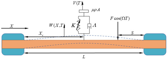
Figure 1.
A mechanical model of an elastic beam coupled with a nonlinear energy sink.
The beam bending motion can be described by transverse displacement W(X, T), where X and T are the axial and the time coordinates, respectively. The governing equation is as follows:
where V is the displacement of nonlinear energy sink mass, and Xc and S are the locations of the nonlinear energy sink and the concentrated force. The boundary conditions at both ends are as follows:
The equilibrium configurations produced by the weights satisfy the static equations derived from Equation (1), as follows:
Under boundary condition (2), the static equilibrium configurations of the beam and the nonlinear energy sink can be solved from Equation (3), as follows:
Taking the static equilibrium configurations as the coordinate origin, consequently, W1(X, T) = W(X, T) − W0(X) and V1(T) = V(T) − V0, namely, as follows:
The substitution of Equation (5) into Equation (1) leads to the following governing equation, measured from the equilibrium configurations:
Equation (6) can be transformed into the dimensionless form, as follows:
where
It should be remarked that the beam weight does not appear in the governing equation, the first equation in Equation (7). It is balanced by the static deformation effect.
The corresponding boundary conditions are as follows:
In all available works, the weights are assumed to be balanced by the static deflection. Thus, the corresponding governing equations measured from the equilibrium configurations are as follows:
Equation (10) can be transformed into the dimensionless form, as follows:
where
3. Discretization via the Galerkin Method
Based on the weight functions ϕi(x)(i = 1, 2,…, N), the dimensionless beam transverse displacements are assumed to take the following form:
where qi(t) is the corresponding generalized coordinate. Consequently, Equation (7) can be discretized as follows:
When both the weight functions and the trial functions are the mode functions of the beam without the damping, the external excitation, and the nonlinear energy sink, the Galerkin method transforms Equation (14) into the truncated form, with the first N terms in Equation (13), as follows:
where
In the case that the weights are balanced by the static deflection, Equation (11) is similarly truncated as follows:
The restoring forces for upward and downward motion are not symmetrical, due to the quadratic nonlinearity in Equation (17). In Equation (15), only cubic nonlinearity exists, and the restoring force is symmetrical.
The modal function of the beam can be written as follows, without the damping, the external excitation, and the nonlinear energy sink:
where the undetermined coefficients Hj(j = 1, 2, 3, 4) and the eigenvalue β can be obtained through the boundary conditions of the beam. Then, the first six natural frequencies of the beam can be obtained by using the parameters in Table 1, which are f1 = 21.43 Hz, f2 = 59.07 Hz, f3 = 115.81 Hz, f4 = 191.45 Hz, f5 = 285.99 Hz, and f6 = 399.45 Hz.

Table 1.
Physical and geometric parameters of beam.
The first six mode functions are as follows:
The first six mode functions can be used for convergence analysis via the Runge–Kutta method and dynamic response analysis via the harmonic balance method, respectively.
To determine the truncation term number N, the free and the forced vibrations are computed by up to two-, four-, and six-term Galerkin truncation. The parameters of the beam and nonlinear energy sink shown in Table 1 and Table 2 are used in the following analysis. The parameters of the nonlinear energy sink may not be optimal, because the present work focuses on the effect of nonlinear energy sink weight on the responses, rather than the effect of the vibration reduction design.

Table 2.
Physical parameters of nonlinear energy sink.
As for free vibration, the Runge–Kutta method is utilized based on Equation (15), with the first N terms. The excitation amplitude is set as F = 0 N/m. The dimensionless initial values of the beam and nonlinear energy sink are set as follows:
The truncation coefficients and the generalized coordinates of the beam can be described as ϕi(xc)(i = 1,…,N) and qi(t)(i = 1,…,N) in Equation (13). Based on Equation (15), utilizing the Runge–Kutta method, Figure 2 can be obtained to illustrate the time history responses of the free vibration of the one-eighth and one-fourth points of the beam when the effect of weight is considered.
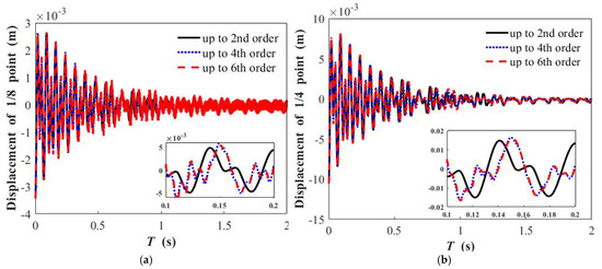
Figure 2.
Time history curve of free vibration when nonlinear energy sink weight is considered, with different truncated orders: (a) displacement of 1/8 point when nonlinear energy sink is placed at 1/2 point of beam; (b) displacement of 1/4 point when nonlinear energy sink is placed at 1/2 point of beam.
As regards the weight being offset by the static deformation change, the numerical solutions via the Runge–Kutta method are calculated based on Equation (17). Figure 3 illustrates the time history responses of free vibration when the effect of weight is neglected.
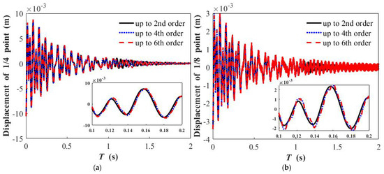
Figure 3.
Time history curve of free vibration when nonlinear energy sink weight is neglected, with different truncated orders: (a) displacement of 1/8 point when nonlinear energy sink is placed at 1/2 point of beam; (b) displacement of 1/4 point when nonlinear energy sink is placed at 1/2 point of beam.
For forced vibrations, the amplitude–frequency responses with different Galerkin truncations (N = 2, 4, 6) are shown to determine the Galerkin truncation order. The excitation amplitude is set as F = 30 N/m. The initial displacements and velocities of the beam and nonlinear sink are all set as 0. By extracting the average value of amplitude during the steady–state response time period at different excitation frequencies, based on Galerkin truncation, the amplitude–frequency response curves of the forced vibration can then be obtained when the weights are considered or not, as shown in Figure 4 and Figure 5.
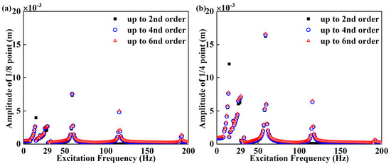
Figure 4.
Amplitude−frequency response of forced vibration when nonlinear energy sink weight is considered, with different orders of Galerkin truncation: (a) 1/8 point of beam when nonlinear energy sink is placed at 1/2 point of beam, (b) 1/4 point of beam when nonlinear energy sink is placed at 1/2 point of beam.
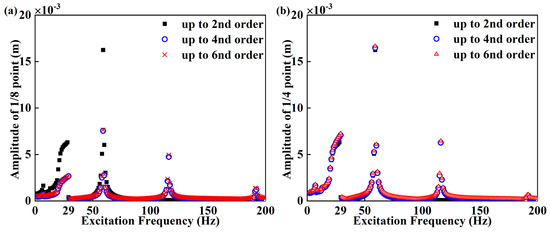
Figure 5.
Amplitude−frequency response of forced vibration when nonlinear energy sink weight is neglected, with different orders of Galerkin truncation: (a) 1/8 point of beam when nonlinear energy sink is placed at 1/2 point of beam, (b) 1/4 point of beam when nonlinear energy sink is placed at 1/2 point of beam.
The numerical solutions up to fourth- and sixth-order truncations are coincident, while the responses up to second-order truncation are lower than the responses up to fourth- and sixth-order truncations at the third- and fourth-order natural frequencies. The responses up to second-order truncation are higher than the responses up to fourth- and sixth-order truncations at the first-order natural frequency. Hence, the subsequent results will be computed based on the fourth-order Galerkin truncation.
4. Harmonic Balance Analysis of the Discrete Modal
After the Galerkin truncation, the harmonic balance method was utilized to theoretically investigate the vibration of the beam. Firstly, with respect to the fact that weights cannot be offset with static deformations, the harmonic hypothesis solutions of Equation (15) can be set as follows:
where qi and v are the generalized coordinates of the beam and nonlinear energy sink based on the Galerkin truncation, respectively. i is the Galerkin truncation order, which is determined in Section 3. The nonlinear force term can be expanded by 0, 1, 2, 3, 1/3, and 2/3 power in Equation (15); then, R and S1, which are the harmonic orders, are set as 2 and 3, respectively. The constant terms ai,0 and av,0 correspond with the 0-power harmonic term. ai,r,3, bi,r,3, ai,s, and bi,s are the undetermined harmonic coefficients of qi. aV,0, aV,r,3, bV,r,3, aV,s, and bV,s are the undetermined harmonic coefficients of v, and ω and t are the excitation frequency and time, respectively.
Secondly, the algebraic equations can be acquired from differential equations by substituting Equation (21) into Equation (15) and extracting the coefficients corresponding to each harmonic order. The algebraic equations for the unknown harmonic coefficients are obtained.
Thirdly, the algebraic equations are solved by the pseudo-arc-length continuation algorithm. Newton’s method is used to calculate the initial values of these algebraic equations. According to the pseudo-arc-length continuation algorithm, the inflection points on the frequency response curves are successfully passed. The pseudo-arc-length continuation algorithm takes the arc length of the curves as the medium to solve the equation. At the same time, according to the predicted values of Newton’s iterative correction equations, the harmonic coefficients are obtained, then the amplitude at the excitation frequency ω is obtained. The amplitudes corresponding to a series of excitation frequencies ω are depicted in Figure 6. In Figure 6 and Figure 7, it can be seen from the enlarged image that the characteristics of the nonlinear vibrations of the beam exhibit the coexistence of softening and hardening features. The solid lines represent the approximate analytical solution obtained by the harmonic balance method, and the box or points represent the numerical results.
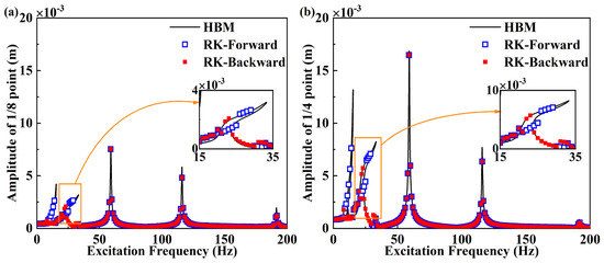
Figure 6.
Comparison of amplitude−frequency curves of analytic solution and numerical solution when nonlinear energy sink weight is considered: (a) 1/8 point of beam when nonlinear energy sink is placed at 1/2 point of beam, (b) 1/4 point of beam when nonlinear energy sink is placed at 1/2 point of beam.
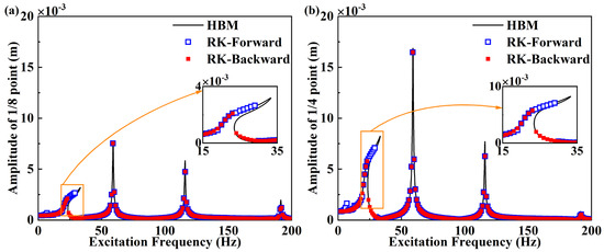
Figure 7.
Comparison of amplitude−frequency curves of analytic solution and numerical solution when nonlinear energy sink weight is neglected: (a) 1/8 point of beam when nonlinear energy sink is placed at 1/2 point of beam, (b) 1/4 point of beam when nonlinear energy sink is placed at 1/2 point of beam.
Under the assumption that weights are offset with static deformations, the solutions of Equation (17) are assumed to be the following:
where i is the Galerkin truncation order and S2 is the harmonic order. In Equation (17), the expansion terms only contain terms of 0, 1, 2, and 3 power. As such, S2 is set as 3 and the Galerkin truncation order is determined as 4 in Section 3, which means that i is set as 4. The amplitude–frequency responses, theoretically and numerically investigated with regard to the assumption that the weights cannot be offset with static deformations, are shown in Figure 7.
The comparisons of the harmonic balance solutions and the numerical solutions via the Runge–Kutta method led to the following observations. When the nonlinear energy sink is placed at the half point of the beam, the numerical and approximate analytical results are coincident. When accounting for the effect of nonlinear energy sink weight, the amplitude–frequency responses appear to be half of a super-harmonic response. The response curves have nonlinear hardening characteristics. Regardless of whether the effect of weight is considered or not, the results calculated by the harmonic balance method agree with the numerical results. Therefore, the harmonic balance method can be used in both cases. The analytical results are accurate and reliable.
5. The Effects of Weight on the Beam’s Vibration
In this section, the effects of weight on the vertical transverse vibrations of a beam with a nonlinear energy sink are investigated. In the following calculations, the parameters of the beam and nonlinear energy sink are shown in Table 1 and Table 2. The Galerkin truncation order N = 4 is determined in Section 3. Based on the Galerkin truncation, Equation (15) is truncated as follows:
In the case that weights are neglected, Equation (17) can be truncated as follows:
5.1. The Free Vibration Simulated by the Runge–Kutta Method
For the free vibration, the influence of weight is studied. The initial dimensionless values are set as follows:
Using the Runge–Kutta method to numerically integrate Equation (23) under the initial conditions, as in Equation (25), the generalized coordinates of the beam qi(t)(i = 1,2,3,4) can be obtained. In the first four terms, the truncation coefficients ϕi(xc)(i = 1,2,3,4) and qi(t)(i = 1,2,3,4) can be multiplied to obtained the displacements of the beam and nonlinear energy sink.
In the case that the weight is neglected, the Runge–Kutta method and the fast Fourier transform are used for Equation (24) to investigate the time responses, as above. As shown in Figure 8, the time histories were obtained. The red lines represent the case considering weight, and the blue lines represent the difference between the displacements when considering and neglecting weight. Compared with the displacement at the one-fourth point, the displacement at the one-eighth point of the beam decays and reaches stability faster. The errors in the figures are defined by subtracting the displacement value when neglecting the weight from the displacement value when considering the weight.
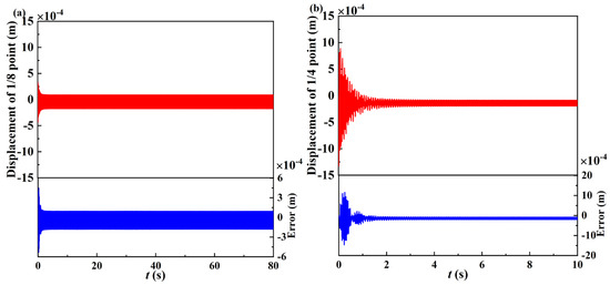
Figure 8.
Time history curve of free vibration: (a) response of 1/8 point of beam when nonlinear energy sink is placed at 1/2 point of beam; (b) response of 1/4 point of beam when nonlinear energy sink is placed at 1/2 point of beam.
All the frequency components of the beam are obtained based on the fast Fourier transform. The numerical and analytical solutions are compared to investigate the differences between the cases where the weights are offset with static deflection and the cases where they are not. Figure 9 depicts the amplitude–frequency diagrams at the one-fourth point and one-eighth point of the beam when the effects of weight are considered and neglected. The details of the amplitude–frequency diagrams are shown in Table 3. Accounting for the nonlinear energy sink weight introduces half super-harmonic responses in addition to the quantitative differences in the first primary harmonic response.
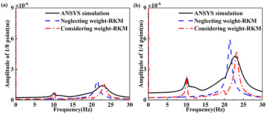
Figure 9.
Amplitude Spectrum of free vibration: (a) response of 1/8 point of beam when nonlinear energy sink is placed at 1/2 point of beam; (b) response of 1/4 point of beam when nonlinear energy sink is placed at 1/2 point of beam.

Table 3.
Comparison of free vibration when nonlinear energy sink is placed at 1/2 point of beam.
5.2. The Forced Vibration of First-Order Primary Frequency, Simulated by the Runge–Kutta Method
The influence of weight on the forced vibration with first-order external primary frequency is discussed in this section. The excitation amplitude is set as F = 30 N/m and the excitation frequency as Ω = 21.43 rad/s. All the initial values of the beam and nonlinear energy sink are set as 0.
The Runge–Kutta method was utilized in Equation (23); then, time history curves could be obtained. The amplitude–frequency diagrams under first-order excitation frequency were obtained by the fast Fourier transform.
In the case that the weights were assumed to be offset by the static deflection, the Runge–Kutta method and the fast Fourier transform were used to obtain the numerical responses based on Equation (24).
As shown in Figure 10, the time histories of forced vibration with first-order excitation frequency were obtained. The red lines represent the case considering weight, and the blue lines represent the differences between the displacements when considering and neglecting weight. For the definition of the error in Figure 10, one can refer to Section 5.1. Figure 11 shows the amplitude–frequency responses under first-order excitation frequency.
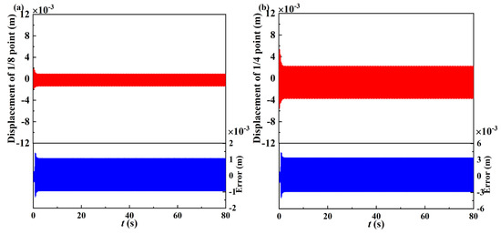
Figure 10.
Time history curve of forced vibration with first−order excitation frequency: (a) response of 1/8 point of beam when nonlinear energy sink is placed at 1/2 point of beam; (b) response of 1/4 point of beam when nonlinear energy sink is placed at 1/2 point of beam.
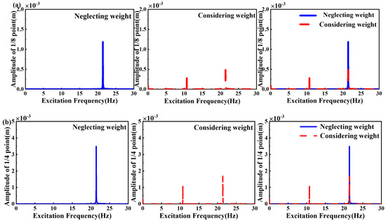
Figure 11.
Amplitude−frequency response of forced vibration with first−order excitation frequency: (a) response of 1/8 point of beam when nonlinear energy sink is placed at 1/2 point of beam; (b) response of 1/4 point of beam when nonlinear energy sink is placed at 1/2 point of beam.
The differences between the numerical and the analytical solutions in the both cases were analyzed. The conclusion can be reached that the displacements of the forced vibration when neglecting weight are larger than that when considering weight. The details of the amplitudes and frequencies when considering and neglecting weight are shown in Table 4. The amplitude–frequency response curves indicate half super–harmonic resonance, in addition to quantitative differences in the first primary resonance.

Table 4.
Comparison of the forced vibration with the 1st order excitation frequency when the nonlinear energy sink is placed at 1/2 point of the beam.
5.3. The Forced Vibration of Second-Order Primary Frequency, Simulated by the Runge–Kutta Method
The influence of weight on the vibration of second-order primary frequency is investigated in this section. The excitation amplitude is set as F = 30 N/m and the excitation frequency as Ω = 59.07 rad/s. The initial values of the beam and the nonlinear energy sink are all given as 0.
The Runge–Kutta method was utilized to obtain the time history curves. Based on Equation (23), in the case that the weights were assumed to be balanced by the static deflection, the Runge–Kutta method was used to investigate the time responses.
The time history curves of the forced vibration with the second-order excitation frequency are shown in Figure 12. For the definition of the error in Figure 12, one can refer to Section 5.1. Figure 13 shows the amplitude–frequency diagrams under second-order excitation frequency obtained by the fast Fourier transform.
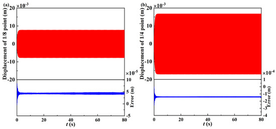
Figure 12.
Time history curve of forced vibration with second−order excitation frequency: (a) response of 1/8 point of beam when the nonlinear energy sink is placed at 1/2 point of beam; (b) response of 1/4 point of beam when nonlinear energy sink is placed at 1/2 point of beam.
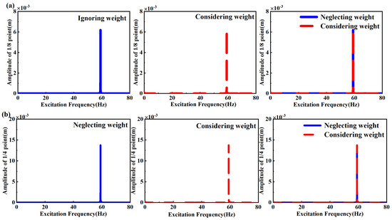
Figure 13.
Amplitude−frequency response of forced vibration with second−order excitation frequency: (a) response of 1/8 point of beam when nonlinear energy sink is placed at 1/2 point of beam; (b) response of 1/4 point of beam when nonlinear energy sink is placed at 1/2 point of beam.
Comparisons of time histories when considering and neglecting weight were investigated. After the fast Fourier transform, the frequency components and corresponding amplitudes are depicted as Table 5. It can be seen that the displacements of the one-fourth point and one-eighth point of the beam are nearly coincident, whether the weight is considered or not. The comparisons indicate that there exists no new frequency component when the beam is under the excitation frequency of second resonance frequency, nor when the excitation frequency changes to the third or fourth resonance frequency.

Table 5.
Comparison of forced vibration with 2nd-order excitation frequency when nonlinear energy sink is at 1/2 point of beam.
6. Finite Element Simulations and Verification
The finite element method was applied to simulate the beam vibrations. In particular, ANSYS software (version number:2.2.1) was used to calculate the responses of the beam with a nonlinear energy sink under an external excitation. Firstly, the element type BEAM188 is adopted. The material parameters of the beam are also set, namely the density, the Poisson’s ratio, and the Young’s modulus. Then, the beam model can be established using node coordinates. Secondly, the beam is meshed into 24 units and fixed support constraints are applied at both beam ends. The cross–sectional size parameters of the beam are entered. For the realization of a nonlinear energy sink, the MASS21 element, the COMBINE39 element, and the Spring14 unit are set to represent the mass, the nonlinear stiffness, and the linear damping of the nonlinear energy sink, respectively. The nonlinear stiffness is achieved by inputting loads and corresponding deformation values in the COMBINE39 element. The external excitation function is set and applied to the quarter node of the beam. Finally, the solver is set to a transient structure to obtain a time history duration of 80s and a time step of 0.001 s. The results obtained from ANSYS Software (version number:2.2.1) were compared with the model-based solutions calculated by the Runge–Kutta method and the harmonic balance method. It was shown that the finite element solutions were closer to the model-based results considering the effect of weights.
The finite element simulation results were compared with the model-based numerical and analytical responses obtained in Section 5. These comparisons require defining the errors between the simulation and the model-based numerical results. The error between the results calculated by the Runge–Kutta method and ANSYS software (version number:2.2.1) is defined as follows:
where ARK is the amplitude calculated by the Runge–Kutta method and AANSYS is the amplitude calculated by the ANSYS software (version number:2.2.1).
The error between the result calculated by the harmonic balance method and ANSYS software (version number:2.2.1) is defined as follows:
where AHBM is the amplitude calculated by the harmonic balance method and AANSYS is the amplitude calculated by the ANSYS software (version number:2.2.1).
6.1. The Free Vibration, Simulated by ANSYS Software
For simulations of the free vertical transverse vibrations of a beam with a nonlinear energy sink using ANSYS software (version number:2.2.1), the displacement was set as 0 m and the initial velocity of the beam was set as 0.2 m/s in the software. The external excitation amplitude was set as 0.
After calculation by the ANSYS software (version number:2.2.1), time history curves could be obtained. The fast Fourier transform was applied to obtain amplitude spectrum curves. Compare the results calculated by the Runge–Kutta method and ANSYS software (version number:2.2.1), as shown in Figure 14. The details of amplitude spectra are shown in Table 6.
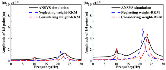
Figure 14.
Amplitude spectra of free vibration of ANSYS software (version number:2.2.1) simulation and Runge−Kutta method when nonlinear energy sink is placed at 1/2 point of beam: (a) frequency response of 1/8 point of beam; (b) frequency response of 1/4 point of beam.

Table 6.
Comparison of free vibration results calculated by ANSYS software (version number:2.2.1) and Runge–Kutta method when nonlinear energy sink is at 1/2 point of beam.
For the assumption that weights are offset with the static deformation, the amplitude spectra determined by the Runge–Kutta method agree well with those calculated by ANSYS software (version number:2.2.1). When the nonlinear energy sink is placed at the half point of the beam, the amplitude spectra of the one-fourth point of the beam, corresponding with two peaks calculated by the Runge–Kutta method, are 10.15 Hz and 23.21 Hz, which correspond to amplitudes of 2.32 × 10⁻⁶ m and 4.77 × 10⁻⁶ m. The results calculated by the ANSYS software (version number:2.2.1) are 10.16 Hz and 22.84 Hz, whose corresponding amplitudes are 2.11 × 10⁻⁶ m and 4.28 × 10⁻⁶ m. When the weight is neglected, the results calculated by the Runge–Kutta method are 21.42 Hz and 5.87 × 10⁻⁶ m. The detailed data of the amplitude spectra of the one-eighth point of the beam yield the same conclusion. When weight is considered, the results calculated by ANSYS and the Runge–Kutta method agree well.
When the nonlinear energy sink is placed at the half point of beam, the amplitude spectra and the detailed data are shown in Figure 14 and Table 6. All in all, the model-based numerical results of the free vibration considering the weight agree well with the results calculated by the ANSYS software (version number:2.2.1).
6.2. The Forced Vibration of the First-Order Primary Frequency, Simulated by ANSYS Software
The simulation of the forced vibration in ANSYS software (version number:2.2.1) for the first-order primary excitation frequency is addressed in this section. After the calculation with the ANSYS software (version number:2.2.1), the time history curves can be obtained, and then the fast Fourier transform is used to obtain the amplitude–frequency response curves.
When the nonlinear energy sink is placed at the half point of the beam, the frequency components and the corresponding amplitudes of the one-fourth and one-eighth points of beam are shown in Figure 15 and Table 7. It can be seen that the frequency results calculated by the Runge–Kutta method when the weight is considered are 10.69 Hz and 21.45 Hz, and when the weight is neglected, the frequency is 21.45 Hz. The frequency results calculated by ANSYS software (version number:2.2.1) are 9.29 Hz and 25.21 Hz. Using the Runge–Kutta method, the amplitudes of the one-fourth point of the beam, corresponding with the frequency referred to above, are 0.98 × 10⁻³ m and 1.89 × 10⁻³ m when the weight is considered, and when the weight is neglected, the amplitude is 3.61 × 10⁻³ m. The amplitudes obtained by ANSYS software (version number:2.2.1) are 1.06 × 10⁻³ m and 1.72 × 10⁻³ m. The errors of the amplitudes obtained by the Runge–Kutta method and ANSYS software (version number:2.2.1) were calculated. It can be seen that the errors are −7.55% and 9.88% when the weight is considered, and the error is 77.33% when the weight is neglected.
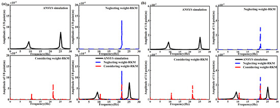
Figure 15.
Results of ANSYS software (version number:2.2.1) simulation and Runge−Kutta method when nonlinear energy sink is placed at 1/2 point of beam: (a) frequency response of 1/8 point of beam; (b) frequency response of 1/4 point of beam.

Table 7.
Comparison of forced vibration with 1st-order excitation frequency, calculated by ANSYS software (version number:2.2.1) and Runge–Kutta method, when nonlinear energy sink is placed at 1/2 point of beam.
From Table 7, the frequency component of the one-eighth point of the beam is the same as that of the one-fourth point of the beam. Using the Runge–Kutta method, the amplitudes of the one-eighth point of the beam, corresponding with the frequency referred to above, are 0.31 × 10⁻³ m and 0.67 × 10⁻³ m when the weight is considered, and when the weight is neglected, the amplitude is 1.3 × 10⁻³ m. The amplitudes obtained by ANSYS software (version number:2.2.1) are 0.35 × 10⁻³ m and 0.77 × 10⁻³ m. It can be seen that the errors are −11.43% and −12.98% when the weight is considered, and the error is 68.83% when the weight is neglected. In both the one-fourth point and one-eighth point of the beam, the resonant frequency and amplitude calculated by the Runge–Kutta method when considering weight agree well with the result calculated by the ANSYS software (version number:2.2.1).
For the forced vibration, the results calculated by harmonic balance analysis were compared with that calculated by the ANSYS software (version number:2.2.1), as shown in Figure 16. The details of the amplitude–frequency response curves are shown in Table 8.
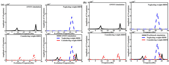
Figure 16.
Results of ANSYS software (version number:2.2.1) simulation and harmonic balance method when nonlinear energy sink is placed at 1/2 point of beam: (a) frequency response of 1/8 point of beam; (b) frequency response of 1/4 point of beam.

Table 8.
Comparison of forced vibration with 1st-order excitation frequency, calculated by ANSYS software (version number:2.2.1) and harmonic balance method, when nonlinear energy sink is at 1/2 point of beam.
Firstly, the situation in which the nonlinear energy sink placed at the half point of the beam is discussed. From Table 8, the frequency components of the one-fourth point of the beam calculated by the harmonic balance method when the weight is considered are 11.83 Hz and 23.67 Hz, and when the weight is neglected, the frequency is 21.43 Hz. The frequency results calculated by ANSYS are 9.29 Hz and 25.21 Hz. Using the harmonic balance method, the amplitudes of the one-fourth point of the beam, corresponding to the frequency referred to above, are 1.18 × 10⁻³ m and 1.91 × 10⁻³ m when the weight is considered, and when the weight is neglected, the amplitude is 4.82 × 10⁻³ m. The amplitudes obtained by the ANSYS software (version number:2.2.1) are 1.06 × 10⁻³ m and 1.72 × 10⁻³ m. The errors of amplitude obtained by the harmonic balance method and ANSYS software (version number:2.2.1) were calculated. It can be seen that the errors are −11.32% and −11.05% when the weight is considered, and the error is 180.23% when the weight is neglected.
The amplitudes of the one-eighth point of the beam obtained by the ANSYS software (version number:2.2.1) are 0.35 × 10⁻³ m and 0.65 × 10⁻³ m. It can be seen that the errors are 0% and −15.58% when the weight is considered, and the error is 112% when the weight is neglected. Obviously, the results calculated by the harmonic balance method when the weight is considered are closer to the results calculated by the ANSYS software (version number:2.2.1) when the nonlinear energy sink is placed at the half point of the beam.
6.3. The Forced Vibration of the Second-Order Primary Frequency, Simulated by ANSYS Software
The frequency–amplitude responses calculated by ANSYS software (version number:2.2.1) when the excitation frequency changed to the second-order primary frequency are shown in this section. After the calculations were carried out by the software, the time history curves could be obtained, then the fast Fourier transform was applied to obtain the diagram of frequency response curves. Figure 17 shows the comparision of the results calculated by the ANSYS software (version number:2.2.1) and the Runge–Kutta method. The detailed data are depicted in Table 9. Using the harmonic balance method, the displacements of the beam under the second-order primary frequency excitation could be obtained. Then, the fast Fourier transform was applied to obtain the diagram of frequency response curves. Figure 18 compares the results calculated by the ANSYS software (version number:2.2.1) and the harmonic balance method. Table 10 depicts the frequencies and amplitudes of the responses.
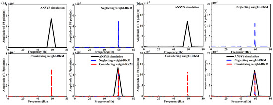
Figure 17.
Results of ANSYS software (version number:2.2.1) simulation and Runge−Kutta method when nonlinear energy sink is placed at 1/2 point of beam with second−order primary frequency excitation: (a) frequency response of 1/8 point of beam; (b) frequency response of 1/4 point of beam.

Table 9.
Comparison of forced vibration with 2nd-order excitation frequency, calculated by ANSYS software (version number:2.2.1) and the Runge–Kutta method, when nonlinear energy sink is at 1/2 point of beam.
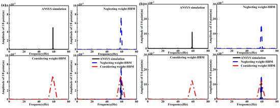
Figure 18.
Results of ANSYS software (version number:2.2.1) simulation and harmonic balance method when nonlinear energy sink is placed at 1/2 point of beam with second-order primary frequency excitation: (a) frequency response of 1/8 point of beam; (b) frequency response of 1/4 point of beam.

Table 10.
Comparison of forced vibration with 2nd-order excitation frequency, calculated by ANSYS software (version number:2.2.1) and harmonic balance method, when nonlinear energy sink is at 1/2 point of beam.
7. Conclusions
A fundamental issue was investigated to understand the effects of nonlinear energy sink weight on the vibration of transverse beams in the vertical direction. The governing equations considering and neglecting the nonlinear energy sink weight were derived. The Galerkin truncation was applied to discretize the governing equations. The harmonic balance method was applied to seek the approximate analytical expressions of the amplitude–frequency responses. Finite element simulations, independent of the governing equations, were implemented via ANSYS software (version number:2.2.1). This investigation yielded the following conclusions:
- (1)
- Accounting for the nonlinear energy sink weight results in an additional linear coupling term and an additional quadratic stiffness term in the governing equation of the vertical transverse vibration beam with a nonlinear energy sink.
- (2)
- For the free vibration, the numerical amplitude spectra reveal that accounting for the nonlinear energy sink weight introduces a half super–harmonic response in addition to quantitative differences in the first primary harmonic response.
- (3)
- For the forced vibration, the amplitude–frequency response curves indicate that accounting for the nonlinear energy sink weight introduces half super–harmonic resonance in addition to quantitative differences in the first primary resonance.
- (4)
- The finite element solutions are closer to the model-based results when considering the nonlinear energy sink weight.
- (5)
- The present investigation demonstrates that the nonlinear energy sink weight effects are significant for transverse beam vibrations in the vertical direction.
Author Contributions
X.F.: conceptualization, methodology, software, writing—original draft, preparation. S.W.: resources, writing—review and editing, supervision, funding acquisition. H.D.: resources, funding acquisition. L.-Q.C.: conceptualization, methodology, writing—review and editing, supervision. All authors have read and agreed to the published version of the manuscript.
Funding
This research was funded by the National Science Fund for Distinguished Young Scholars, grant number 12025204, and the Program of Shanghai Municipal Education Commission, grant number 2019-01-07-00-09-E00018.
Institutional Review Board Statement
Not applicable.
Informed Consent Statement
Not applicable.
Data Availability Statement
The data used to support the findings of this study are available from the corresponding author upon request.
Acknowledgments
The authors would like to thank all the peer reviewers and editors for their valuable contributions to this work.
Conflicts of Interest
The authors declare that they have no known competing financial interests or personal relationships that could have appeared to influence the work reported in this paper.
References
- Ding, H.; Chen, L.Q. Designs, analysis, and applications of nonlinear energy sinks. Nonlinear Dyn. 2020, 100, 3061–3107. [Google Scholar] [CrossRef]
- Geng, X.F.; Ding, H.; Ji, J.C.; Wei, K.X.; Jing, X.J.; Chen, L.Q. A state-of-the-art review on the dynamic design of nonlinear energy sinks. A state-of-the-art review on the dynamic design of nonlinear energy sinks. Eng. Struct. 2024, 313, 118228. [Google Scholar] [CrossRef]
- Kani, M.; Khadem, S.E.; Pashaei, M.H.; Dardel, M. Design and performance analysis of a nonlinear energy sink attached to a beam with different support conditions. Proc. Inst. Mech. Eng. Part C J. Mech. Eng. Sci. 2016, 230, 527–542. [Google Scholar] [CrossRef]
- Zhang, Y.W.; Hou, S.; Xu, K.F.; Yang, T.Z.; Chen, L.Q. Forced vibration control of an axially moving beam with an attached nonlinear energy sink. Acta Mech. Solida Sin. 2017, 30, 674–682. [Google Scholar] [CrossRef]
- Zhang, Y.W.; Yuan, B.; Fang, B.; Chen, L.Q. Reducing thermal shock-induced vibration of an axially moving beam via a nonlinear energy sink. Nonlinear Dyn. 2017, 87, 1159–1167. [Google Scholar] [CrossRef]
- Chen, J.E.; Zhang, W.; Yao, M.H.; Liu, J.; Sun, M. Thermal effect on dynamics of beam with variable-stiffness nonlinear energy sink. Int. J. Nonlinear Sci. Numer. Simul. 2020, 21, 1–10. [Google Scholar] [CrossRef]
- Chang, Z.Y.; Chen, J.; Li, Q.S. Vibration suppression for an elastically supported nonlinear beam coupled to an inertial nonlinear energy sink. Int. J. Struct. Stab. Dyn. 2023, 23, 2340017. [Google Scholar] [CrossRef]
- Fang, B.; Theurich, T.; Krack, M.; Bergman, L.A.; Vakakis, A.F. Vibration suppression and modal energy transfers in a linear beam with attached vibro-impact nonlinear energy sinks. Commun. Nonlinear Sci. 2020, 91, 105415. [Google Scholar] [CrossRef]
- Li, W.K.; Wierschem, N.E.; Li, X.H.; Yang, T.J.; Brennan, M.J. Numerical study of a symmetric single-sided vibro-impact nonlinear energy sink for rapid response reduction of a cantilever beam. Nonlinear Dyn. 2020, 100, 951–971. [Google Scholar] [CrossRef]
- Fang, S.T.; Chen, K.Y.; Xing, J.T.; Zhou, S.X.; Liao, W.H. Tuned bistable nonlinear energy sink for simultaneously improved vibration suppression and energy harvesting. Int. J. Mech. Sci. 2021, 212, 106838. [Google Scholar] [CrossRef]
- He, M.X.; Tang, Y.; Ding, Q. Dynamic analysis and optimization of a cantilevered beam with both the acoustic black hole and the nonlinear energy sink. J. Intell. Mater. Syst. Struct. 2022, 33, 70–83. [Google Scholar] [CrossRef]
- Zhang, Y.W.; Zhang, Z.; Chen, L.Q.; Yang, T.Z.; Fang, B.; Zang, J. Impulse-induced vibration suppression of an axially moving beam with parallel nonlinear energy sink. Nonlinear Dyn. 2015, 82, 61–71. [Google Scholar] [CrossRef]
- Xu, J.J.; Leng, Y.G.; Su, X.K.; Chen, X.Y. Efficiency evaluation of the enhanced nonlinear energy sink with electromagnetic energy harvesting mechanism. J. Vib. Control 2024, 1–14. [Google Scholar] [CrossRef]
- Dou, J.X.; Yao, H.L.; Cao, Y.B.; Li, H. Performance improvement of nonlinear energy sink based on eddy current damping. Mech. Syst. Signal Process. 2023, 188, 109994. [Google Scholar] [CrossRef]
- Parseh, M.; Dardel, M.; Ghasemi, M.H.; Pashaei, M.H. Steady state dynamics of a non-linear beam coupled to a nonlinear energy sink. Int. J. Nonlinear Mech. 2016, 79, 48–65. [Google Scholar] [CrossRef]
- Chen, J.E.; He, W.; Zhang, W.; Yao, M.H.; Liu, J.; Sun, M. Vibration suppression and higher branch responses of beam with parallel nonlinear energy sinks. Nonlinear Dyn. 2018, 91, 885–904. [Google Scholar] [CrossRef]
- Zhang, Y.W.; Hou, S.; Zhang, Z.; Zang, J.; Ni, Z.Y.; Teng, Y.Y.; Chen, L.Q. Nonlinear vibration absorption of laminated composite beams in complex environment. Nonlinear Dyn. 2020, 99, 2605–2622. [Google Scholar] [CrossRef]
- Moslemi, A.; Khadem, S.E.; Khazaee, M.; Davarpanah, A. Nonlinear vibration and dynamic stability analysis of an axially moving beam with a nonlinear energy sink. Nonlinear Dyn. 2021, 104, 1955–1972. [Google Scholar] [CrossRef]
- Zang, J.; Cao, R.Q.; Zhang, Y.W. Steady-state response of a viscoelastic beam with asymmetric elastic supports coupled to a lever-type nonlinear energy sink. Nonlinear Dyn. 2021, 105, 1327–1341. [Google Scholar] [CrossRef]
- Zhang, Z.; Ding, H.; Zhang, Y.W.; Chen, L.Q. Vibration suppression of an elastic beam with boundary inerter-enhanced nonlinear energy sinks. Acta Mech. Sin. 2021, 37, 387–401. [Google Scholar] [CrossRef]
- Zhang, Z.; Gao, Z.T.; Fang, B.; Zhang, Y.W. Vibration suppression of a geometrically nonlinear beam with boundary inertial nonlinear energy sinks. Nonlinear Dyn. 2022, 109, 1259–1275. [Google Scholar] [CrossRef]
- Zhang, W.; Chang, Z.Y.; Chen, J. Vibration reduction for an asymmetric elastically supported beam coupled to an inertial nonlinear energy sink. J. Vib. Eng. Technol. 2023, 11, 1711–1723. [Google Scholar] [CrossRef]
- Zhang, W.Y.; Niu, M.Q.; Chen, L.Q. Vibration reduction of a Timoshenko beam with multiple parallel nonlinear energy sinks. Appl. Sci. 2022, 12, 9008. [Google Scholar] [CrossRef]
- Zhao, Y.H.; Du, J.T.; Chen, Y.L.; Liu, Y. Dynamic behavior and vibration suppression of a generally restrained pre-pressure beam structure attached with multiple nonlinear energy sinks. Acta Mech. Solida Sin. 2023, 36, 116–131. [Google Scholar] [CrossRef]
- Ye, S.Q.; Mao, X.Y.; Ding, H.; Ji, J.C.; Chen, L.Q. Nonlinear vibrations of a slightly curved beam with nonlinear boundary conditions. Int. J. Mech. Sci. 2020, 168, 105294. [Google Scholar] [CrossRef]
- Li, H.Q.; Li, A.; Kong, X.R. Design criteria of bistable nonlinear energy sink in steady-state dyna- mics of beams and plates. Nonlinear Dyn. 2021, 103, 1475–1497. [Google Scholar] [CrossRef]
- Karlicic, D.; Cajic, M.; Paunovic, S.; Adhikari, S. Periodic response of a nonlinear axially moving beam with a nonlinear energy sink and piezoelectric attachment. Int. J. Mech. Sci. 2021, 195, 106230. [Google Scholar] [CrossRef]
- Wang, Y.F.; Kang, H.J.; Cong, Y.Y.; Guo, T.D.; Fu, T. Nonlinear dynamic analysis of a cable-stayed beam with a nonlinear energy sink. Acta Mech. 2024, 235, 1921–1944. [Google Scholar] [CrossRef]
- Wang, Y.F.; Kang, H.J.; Cong, Y.Y.; Guo, T.D.; Fu, T. Vibration suppression of a cable-stayed beam by a nonlinear energy sink. Nonlinear Dyn. 2023, 111, 14829–14849. [Google Scholar] [CrossRef]
- Ma, J.J.; Liu, Z.T.; Wang, C.S.; Liu, F.J.; Li, D.; Guo, Y.; Cai, J.C. Nonlinear energy sink vibration suppression and parameter optimization of a finite-length beam on the elastic medium based on the modified Winkler theory. Nonlinear Dyn. 2024, 112, 59–80. [Google Scholar] [CrossRef]
- Zhao, J.; Liu, J.Q.; Lyu, M.; Liu, P.B. Design of nonlinear energy sink based on bistable cosine-shaped beam. In Proceedings of the 2019 IEEE 9th Annual International Conference on CYBER Technology in Automation, Control, and Intelligent Systems (CYBER), Suzhou, China, 29 July–2 August 2019; pp. 435–438. [Google Scholar]
- Mattei, P.O.; Poncot, R.; Pachebat, M.; Cote, R. Nonlinear targeted energy transfer of two coupled cantilever beams coupled to a bistable light attachment. J. Sound Vib. 2016, 373, 29–51. [Google Scholar] [CrossRef]
- Yao, H.L.; Liu, S.; Wang, Y.W.; Wen, B.C. Adjustable permanent magnet bi-stable nonlinear energy sink and its application. J. Vib. Shock 2020, 39, 127–133. [Google Scholar]
- Fang, X.; Wen, J.H.; Yin, J.F.; Yu, D.L. Highly efficient continuous bistable nonlinear energy sink composed of a cantilever beam with partial constrained layer damping. Nonlinear Dyn. 2017, 87, 2677–2695. [Google Scholar] [CrossRef]
- Chen, L.Q.; Li, X.; Lu, Z.Q.; Zhang, Y.W.; Ding, H. Dynamic effects of weights on vibration reduction by a nonlinear energy sink moving vertically. J. Sound Vib. 2019, 451, 99–119. [Google Scholar] [CrossRef]
- Li, X.; Ding, H.; Chen, L.Q. Effects of weights on vibration suppression via a nonlinear energy sink under vertical stochastic excitations. Mech. Syst. Signal Process. 2022, 173, 109073. [Google Scholar] [CrossRef]
- Chen, W.; Hu, Z.Y.; Dai, H.L.; Wang, L. Extremely large-amplitude oscillation of soft pipes conveying fluid under gravity. Appl. Math. Mech. 2020, 41, 1381–1400. [Google Scholar] [CrossRef]
- Béri, B.; Stépán, G.; Hogan, S.J. Effect of potential energy variation on the natural frequency of an Euler-Bernoulli cantilever beam under lateral force and compression. J. Appl. Mech. 2017, 84, 051002. [Google Scholar] [CrossRef]
- Xi, L.Y.; Li, X.F.; Tang, G.J. Free vibration of standing and hanging gravity-loaded Rayleigh cantilevers. Int. J. Mech. Sci. 2013, 66, 233–238. [Google Scholar] [CrossRef]
- Virgin, L.N.; Santillan, S.T.; Holland, D.B. Effect of gravity on the vibration of vertical cantilevers. Mech. Res. Commun. 2007, 34, 312–317. [Google Scholar] [CrossRef]
- Li, H.Q.; Li, A.; Zhang, Y.F. Importance of gravity and friction on the targeted energy transfer of vibro-impact nonlinear energy sink. Int. J. Impact Eng. 2021, 157, 104001. [Google Scholar] [CrossRef]
- Yokoyama, T. Vibrations of a hanging Timoshenko beam under gravity. J. Sound Vib. 1990, 141, 245–258. [Google Scholar] [CrossRef]
- Rivero-Rodriguez, J.; Pérez-Saborid, M. Numerical investigation of the influence of gravity on flutter of cantilevered pipes conveying fluid. J. Fluid. Struct. 2015, 55, 106–121. [Google Scholar] [CrossRef]
- Wang, G.X.; Ding, H.; Chen, L.Q. Dynamic effect of internal resonance caused by gravity on the nonlinear vibration of vertical cantilever beams. J. Sound Vib. 2020, 474, 115265. [Google Scholar] [CrossRef]
- Xu, Q.P.; Liu, J.Y. An improved dynamic model for a silicone material beam with large deformation. Acta Mech. Sin. 2018, 34, 744–753. [Google Scholar] [CrossRef]
- Farid, M.; Gendelman, O.V. Tuned pendulum as nonlinear energy sink for broad energy range. J. Vib. Control 2015, 23, 373–388. [Google Scholar] [CrossRef]
- Serdukova, L.; Kuske, R.; Yurchenko, D. Stability and bifurcation analysis of the period-T motion of a vibro-impact energy harvester. Nonlinear Dyn. 2019, 98, 1807–1819. [Google Scholar] [CrossRef]
- Texier, B.D.; Dorbolo, S. Deformations of an elastic pipe submitted to gravity and internal fluid flow. J. Fluid. Struct. 2015, 55, 364–371. [Google Scholar] [CrossRef]
- Amabili, M.; Carra, S. Experiments and simulations for large-amplitude vibrations of rectangular plates carrying concentrated masses. J. Sound Vib. 2012, 331, 155–166. [Google Scholar] [CrossRef]
- Endo, A.; Itoyama, R.; Kuroda, J.; Uchino, D.; Ogawa, K.; Ikeda, K.; Kato, T.; Narita, T.; Kato, H. Vibration characteristics of flexible steel plate on proposed magnetic levitation system using gravity. Vibration 2022, 5, 936–945. [Google Scholar] [CrossRef]
- Meng, Y.; Mao, X.Y.; Ding, H.; Chen, L.Q. Nonlinear vibrations of a composite circular plate with a rigid body. Appl. Math Mech. 2023, 44, 857–876. [Google Scholar] [CrossRef]
- Treyssède, F. Vibration analysis of horizontal self-weighted beams and cables with bending stiffness subjected to thermal loads. J. Sound Vib. 2010, 329, 1536–1552. [Google Scholar] [CrossRef][Green Version]
- Wang, R.T.; Chou, T.H. Non-linear vibration of timoshenko beam due to a moving force and the weight of beam. J. Sound Vib. 1998, 218, 117–131. [Google Scholar] [CrossRef]
- Mamandi, A.; Kargarnovin, M.H. Nonlinear dynamic analysis of an inclined Timoshenko beam subjected to a moving mass/force with beam’s weight included. Shock Vib. 2011, 18, 875–891. [Google Scholar] [CrossRef]
Disclaimer/Publisher’s Note: The statements, opinions and data contained in all publications are solely those of the individual author(s) and contributor(s) and not of MDPI and/or the editor(s). MDPI and/or the editor(s) disclaim responsibility for any injury to people or property resulting from any ideas, methods, instructions or products referred to in the content. |
© 2025 by the authors. Licensee MDPI, Basel, Switzerland. This article is an open access article distributed under the terms and conditions of the Creative Commons Attribution (CC BY) license (https://creativecommons.org/licenses/by/4.0/).