Article

Dynamic Characteristics and Periodic Stability Analysis of Rotor System with Squeeze Film Damper Under Base Motions

Department of Mechanics and Aerospace Engineering, Southern University of Science and Technology, Shenzhen 518055, China
*
Author to whom correspondence should be addressed.
Appl. Sci. 2025, 15(3), 1186; https://doi.org/10.3390/app15031186
Submission received: 28 December 2024 / Revised: 16 January 2025 / Accepted: 20 January 2025 / Published: 24 January 2025

Abstract

:
Inertial loads induced by base motion excitation introduce significant complexities in equilibrium point determination and linearization of systems incorporating squeeze film dampers (SFDs). The coupled effects of base motion excitation and SFD characteristics on periodic stability have received limited attention in previous investigations. This study investigates the dynamic characteristics and periodic stability of a rotor system with SFD subjected to base motion excitation. A finite element model of the rotor-SFD-support system under non-inertial motion is established. The periodic responses are solved using the harmonic balance method with alternating frequency/time technique (HB-AFT) and the arc-length continuation algorithm incorporating the predictor–corrector method, while system stability is analyzed using Floquet theory and the Newmark method. A systematic parametric study is conducted to investigate the effects of base motion parameters, mass unbalance, and SFD parameters on the system’s periodic response. Results demonstrate that base pitching motion enhances system stability, suppresses bistable responses and jump phenomena, and reduces unstable vibration regions. However, under specific parameter combinations, pitching motion can trigger secondary Hopf bifurcations, leading to quasi-periodic and chaotic motions, among other complex nonlinear behaviors. This research provides theoretical foundations for stability-oriented design optimization of rotor systems with SFDs under base motion excitation.

1. Introduction

The squeeze film damper (SFD), serving as a critical vibration-suppression component in high-speed turbomachinery, enhances system stability and reliability by providing supplementary damping. Due to its unique vibration-suppression mechanism and exceptional performance characteristics, SFD has become an indispensable core component in modern turbomachinery, including aeroengines, gas turbines, and compressors. However, under improper parameter design or adverse operating conditions, the inherent nonlinear characteristics of SFD may trigger system instability, significantly affecting operational performance [1,2,3].
For nonlinear rotor stability analysis, Floquet theory provides a rigorous mathematical foundation for examining the stability of periodic orbits, enabling quantitative stability assessment and prediction of potential bifurcation behavior through the calculation of Floquet multipliers. Regarding computational methods based on Floquet theory, Friedman [4] developed an improved Runge–Kutta algorithm for computing the Floquet monodromy matrix based on Hsu’s method [5]. This method significantly enhanced computational efficiency while maintaining accuracy and has been successfully applied in helicopter rotor blade stability analysis. Peletan et al. [6] systematically compared five stability computation methods based on Floquet theory for periodic solutions, including the shooting method, Hsu’s method, explicit Runge–Kutta integration, implicit Newmark integration, and Hill’s method. Through analyses of both Jeffcott rotor and multi-degree-of-freedom finite element rotor models, the results indicated that the Newmark method demonstrated the most balanced performance in terms of computational efficiency and precision.
Extensive research has been conducted on the nonlinear behavior and stability analysis of rotor systems with SFDs through the application of Floquet theory. Zhao et al. [7,8] revealed that the jump phenomenon in rigid rotor systems with eccentric SFD essentially represents a saddle–node bifurcation, demonstrating that large static eccentricity and mass unbalance can lead to subharmonic and quasi-periodic responses. Bonello et al. [9] developed an improved harmonic balance method combined with Hsu’s method for computing Floquet multipliers, numerically and experimentally validating nonlinear phenomena, including subharmonic resonance, superharmonic resonance, and quasi-periodic motions in eccentric SFD rotor systems. Inayat-Hussain [10] employed numerical integration to investigate the stability effects of unbalance, bearing stiffness, and journal mass on single-disk flexible rotor systems with SFD, identifying period-four and quasi-periodic motions under specific parameter combinations. Chen et al. [11] innovatively combined the harmonic balance method with Newton–Raphson iteration, proposing a novel transfer matrix method and deriving equations for Jeffcott rotor systems with SFD, analyzing systematic stability through Floquet theory. Qin [12] examined support stiffness effects on the stability of Jeffcott rotor systems with elastically supported SFD, revealing that system responses alternate between periodic and quasi-periodic motions within specific speed ranges. In contrast, excessive support stiffness induces 1/4 and 1/2 subharmonic components.
Researchers have conducted investigations into the stability behavior of SFDs under dual-frequency excitation and in coupling with other nonlinear elements. Chen et al. [13] investigated the jump mechanisms of dual-rotor systems with SFD under dual-frequency excitation using the harmonic balance method combined with Runge–Kutta numerical integration, discovering coexisting soft and hard characteristics near the third-order resonance peak. The system transitions from periodic to quasi-periodic solutions through secondary Hopf bifurcation, with increased excitation frequency ratios enhancing system stability. Ri et al. [14] studied the dynamic behavior of rotor-SFD systems with cubic terms using the incremental harmonic balance method (IHB), identifying secondary Hopf bifurcations in second-order resonance regions under specific combinations of SFD centering spring stiffness and nonlinear stiffness parameters. Asymmetric SFD parameters significantly expanded unstable solution regions. Zhang et al. [15] established equations of motion for rotor systems with floating ring bearings using the transfer matrix method, analyzing stability trends under unbalanced forces through Poincaré maps, frequency spectra, and bifurcation diagrams.
In practical engineering applications, rotor systems are typically mounted on moving bases, subjected to additional excitation from base motion beyond rotational excitation. This configuration significantly complicates the dynamic behavior of nonlinear rotor systems, for which researchers have conducted extensive investigations. El-Saeidy and Sticher [16] analyzed the dynamic characteristics of single-disk rotor systems with elastic supports under coupled excitation from mass unbalance and base motion. It demonstrated that under both linear and cubic nonlinear elastic support conditions, the coupling between base harmonic translation or harmonic rotation about the translational axis and unbalanced forces generates periodic and quasi-periodic motions. Dakel et al. [17] investigated rotor-fluid hydrodynamic bearing systems, revealing that the coupling between base harmonic rotation and mass unbalance produces various dynamic responses, including periodic, quasi-periodic, and chaotic motions. Han and Chu [18,19] utilized an Euler beam model and harmonic balance method to investigate base motion effects on two specialized rotor systems (cracked rotors and gear-coupled rotors) and revealed their vibration response characteristics and stability patterns. Chen et al. [20,21,22,23] employed Newmark-HHT numerical integration to investigate the dynamics of rotor systems under base motion excitation with various SFD configurations (π-film, full-film, with/without fluid inertia, with/without static eccentricity of the journal) and revealed that base harmonic translation induces quasi-periodic motions, double-frequency vibrations, and combination frequency responses between excitation and base harmonic frequencies. As the frequency of base harmonic translation increases, system motion evolves from periodic to quasi-periodic and ultimately to chaotic motion, independent of SFD centering condition.
Briend [24] developed a six-degree-of-freedom finite element model incorporating axial translational and rotational displacements for rotor-fluid bearing-support systems. Using Floquet theory and the Newmark method, the coupling effects between mass unbalance and base harmonic motion were analyzed. The results revealed that system instability under unidirectional rotational harmonic excitation stems from single-frequency parametric excitation, and pitching and yawing motions generated more complex instability regions compared to rolling motion. Under uniaxial base harmonic excitation, magnitude and phase angle of mass unbalance significantly affected system stability characteristics. Soni [25] investigated the parametric stability of flexible rotor-magnetic bearing systems under periodic base motion using Hsu’s method and demonstrated that multiple control laws maintain system stability under base rolling, pitching, and yawing motions.
In summary, although existing studies have explored the complex nonlinear dynamic characteristics of nonlinear rotor systems under dual excitation from base harmonic motion and unbalanced forces, research on nonlinear behaviors such as bistable phenomena in rotor systems with SFDs under base motion excitation requires further investigation. In the present study, the harmonic balance method is employed to calculate periodic solutions of the system, coupled with an arc-length continuation algorithm incorporating predictor–corrector schemes for unstable solution tracking. Floquet multipliers are computed via Newmark integration, enabling bifurcation analysis based on Floquet stability theory, while non-periodic response characteristics are validated using the Newmark numerical integration method. Through systematic parametric analysis examining base motion, mass unbalance, and damper parameters, this investigation provides comprehensive insights into the nonlinear dynamic behavior and stability characteristics of rotor-SFD-support systems under base motion excitation.

2. Differential Equations of Motion

2.1. Systematic Equations Under Base Motion Excitation

As shown in Figure 1, to describe the dynamic behavior of a rotor system on a moving base, three Cartesian reference frames are introduced: the inertial reference frame O g x g y g z g fixed to the ground, a non-inertial reference frame O x y z fixed to the rigid base, and a rotor reference frame O r x r y r z r fixed to the center of mass of the rigid disk or shaft section. x 0 , y 0 , z 0 denote the translational displacement components of the base projected onto the reference frame O x y z . The angular velocities ω b x , ω b y , and ω b z represent the base rolling, pitching and yawing motions about the O x , O y , and O z axis, respectively. The axial motion of the system is neglected in this study.
Through the derivation of the motion relationships between different coordinate systems, expressions of kinetic and potential energy can be obtained for both the rigid disk and the shaft element based on Timoshenko beam theory. Utilizing Lagrange’s equations, the equations of motion for the flexible rotor system under base motion can be derived [20]:
M s q ¨ + C s Ω G + C b a s e q ˙ + K s + K b a s e q = F m u + F b a s e + F s f d
where q , q , and q ¨ represent the system’s generalized displacement, velocity, and acceleration vectors, respectively; Ω denotes the rotational speed of the rotor system. M s , C s , K s are the system mass, damping, and stiffness matrices, respectively; G s is the gyroscopic matrix; C b a s e and K b a s e are the additional damping and stiffness matrices induced by base motion; F m u represents the unbalanced force; F s f d denotes the nonlinear oil film force; and F b a s e represents the inertial force terms introduced by base motion. All the matrices and vectors are listed in reference [20]. Taking the disk element as an example, the matrices and external force related to base motion are expressed as follows:
C b a s e = 0 2 m i ω b x 0 0 2 m i ω b x 0 0 0 0 0 0 J i p 2 J i d 0 0 2 J i d J i p 0
K b a s e = m i ω b x 2 + ω b z 2 m i ω ˙ b x + ω b y ω b z 0 0 m i ω ˙ b x + ω b y ω b z m i ω b x 2 + ω b y 2 0 0 0 0 J i p Ω ω b x + J i p d ω b x 2 ω b z 2 J d ω ˙ b x + J i p d ω b y ω b z 0 0 J i p d ω ˙ b x ω b y ω b z J i p Ω ω b x + J i p d ω b x 2 ω b y 2
F b a s e = m i y ¨ 0 + x ˙ 0 ω b z z ˙ 0 ω b x m i x d ω ˙ b z + ω b x ω b y m i z ¨ 0 + y ˙ 0 ω b x x ˙ 0 ω b y + m i x d ω ˙ b y ω b x ω b z J i p Ω + ω b x ω b z J i d ω ˙ b y ω b x ω b z J i p Ω + ω b x ω b y J i d ω ˙ b z + ω b x ω b y
where m i , J i p , and J i d represent the mass, polar moment of inertia, and diametral moment of inertia of the i-th disk element, respectively. J i p d is defined as the difference between polar and diametral moments of inertia ( J i p d = J i p J i d ), and x d denotes the axial position of the disk.

2.2. Mass Unbalance

Under base motion excitation, the unbalanced force generated by the mass unbalance on the disk can be expressed in terms of cosine and sine components in the base coordinate system:
F m u = F m u , c c o s Ω t + F m u , s s i n Ω t
F m u , c = m m u e Ω 2 + 2 Ω ω b x + ω b x 2 + ω b z 2 c o s η + ω ˙ b x ω b y ω b z s i n η ω ˙ b x + ω b y ω b z c o s η + Ω 2 + 2 Ω ω b x + ω b x 2 + ω b y 2 s i n η 0 0
F m u , s = m m u e Ω 2 + 2 Ω ω b x + ω b x 2 + ω b z 2 s i n η + ω ˙ b x ω b y ω b z c o s η ω ˙ b x + ω b y ω b z s i n η + Ω 2 + 2 Ω ω b x + ω b x 2 + ω b y 2 c o s η 0 0
where m m u represents the unbalanced mass, e denotes the eccentricity of the unbalanced mass, and η indicates the phase angle of the unbalance.

2.3. Nonlinear Oil Film Force

As shown in Figure 2, the structure of a squeeze film damper primarily consists of a journal outer ring (or squirrel cage elastic support outer ring) and a fixed bearing housing. The damping effect is generated by the fluid dynamic pressure during periodic squeezing of the lubricating oil in the annular clearance between the inner and outer rings, thereby reducing vibration in the rotor system.
The journal is assumed to maintain parallel alignment with the bearing axis during operation. The short bearing approximation [26,27] and incompressible Reynolds equation are adopted. Then, the transient oil film pressure p in the SFD can be expressed as follows:
x ( h 3 p x ) = 12 μ ψ ˙ s f d h θ + 12 μ h t
where μ represents the lubricating oil viscosity. h = c + e c o s θ is the film thickness. θ is the circumferential coordinate, measured in the local reference frame, beginning on the line connecting the bearing center O b and journal center O j . C is the oil film clearance, e = y 2 + z 2 represents the journal eccentricity, and y , z are the displacements of the squeeze film damper node in the OY and OZ directions. The journal precession angular velocity is given by ψ ˙ s f d = y z ˙ z y ˙ / e 2 .
Through integration, the analytical expressions for radial oil film force F r and tangential oil film force F t can be obtained:
F r = μ R L s f d 3 C 2 ( ε ψ s f d I 1 + ε ˙ I 2 ) , F t = μ R L s f d 3 C 2 ( ε ˙ I 1 + ε ψ s f d I 3 )
where ε = e / c is the dimensionless radial displacement of the oil film, L s f d represents the axial length of the oil film, R is the oil film radius. I 1 , I 2 , I 3 are Sommerfeld integrals [28], expressed as follows:
I 1 = θ 1 θ 2 s i n θ c o s θ 1 + ε c o s θ 2 d θ , I 2 = θ 1 θ 2 c o s 2 θ 1 + ε c o s θ 3 d θ , I 3 = θ 1 θ 2 s i n 2 θ 1 + ε c o s θ 3 d θ
π-film cavitation model is adopted in this paper, where θ 1 = π and θ 2 = 2 π , and consequently, the expressions for the radial and tangential oil film forces and their components projected onto the base reference frame are respectively given as follows:
F r = μ R L s f d 3 c 2 2 ε 2 ψ ˙ s f d 1 ε 2 2 + π 2 1 + 2 ε 2 ε ˙ 1 ε 2 5 / 2 F t = μ R L s f d 3 c 2 π 2 ε ψ ˙ s f d 1 ε 2 3 / 2 + 2 ε ε ˙ 1 ε 2 2
F y = F r c o s ψ s f d + F t s i n ψ s f d F z = F r s i n ψ s f d F t c o s ψ s f d

3. Computational Methods and Validation

3.1. Harmonic Balance Method with Alternating Frequency/Time–Domain Technique

Since the system response contains an excitation frequency related to the rotational speed, the periodic solution of the rotor system and nonlinear oil film forces can be represented by H-order truncated Fourier series:
q = a 0 + j = 1 H a j c o s j Ω t + b j s i n j Ω t F s f d = c 0 + j = 1 H c j c o s j Ω t + d j s i n j Ω t
where a 0 and c 0 are constant terms, and a j , b j , c j , d j are the coefficients to be determined for each truncated Fourier term.
Substituting Equation (13) into Equation (1) and eliminating the cosine and sine harmonic terms yields the system residual equation:
R X = P X + Q n l Q e x
where the coefficient matrix P is expressed as follows:
P = d i a g P 0 P 1 P j 1 P j P j + 1 P H P j = K s + K b r g + K b a s e ( j Ω ) 2 M s i j Ω C b r g + C b a s e Ω G s
where d i a g ( ) denotes the diagonal arrangement of the enclosed matrices to form a block diagonal matrix, and i is the imaginary unit.
The excitation force term Q e x is given as follows:
Q e x = Q 0 ; Q 1 ; 0 ; ; 0
where Q 0 = F b a s e , Q 1 = F m u , c + i F m u , s , and 0 represents the zero vector.
The analytical expression of nonlinear squeeze film forces is difficult to expand through trigonometric function relations. Therefore, the alternating frequency time–domain (AFT) method is required to obtain discrete time–domain information of nonlinear forces. The discrete time–domain information of system response is obtained through inverse discrete Fourier transform (IDFT):
x n = R e j = 0 H X j e i ( 2 π j n ) / N f
where X j = a j i b j ; N f is the number of selected time discretization points, which must be greater than 2 times of the total harmonic number H ; and x n represents the time–domain information of generalized displacement Fourier coefficients at the n-th time point, n = 0 , 1 , 2 , . . . , N f 1 .
Similarly, the expression for x ˙ n can be obtained. Then, the time–domain information of nonlinear force Fourier coefficients f ¯ n l x ˙ n , x n is determined through the explicit expression presented in Equation (12). The frequency-domain information of nonlinear force Fourier coefficients can be obtained using discrete Fourier transform (DFT):
Q n l j = c j i d j = 1 N f n = 0 N f 1 R e ( f ¯ n l ( x ˙ n , x n ) e i 2 π j n / N f ) , j = 0 2 N f n = 0 N f 1 f ¯ n l ( x ˙ n , x n ) e i 2 π j n / N f , j 0
Then, the nonlinear force term Q n l in Equation (14) can be obtained by Q n l = Q n l 0 ; Q n l 1 ; Q n l H 1 ; Q n l H ; .
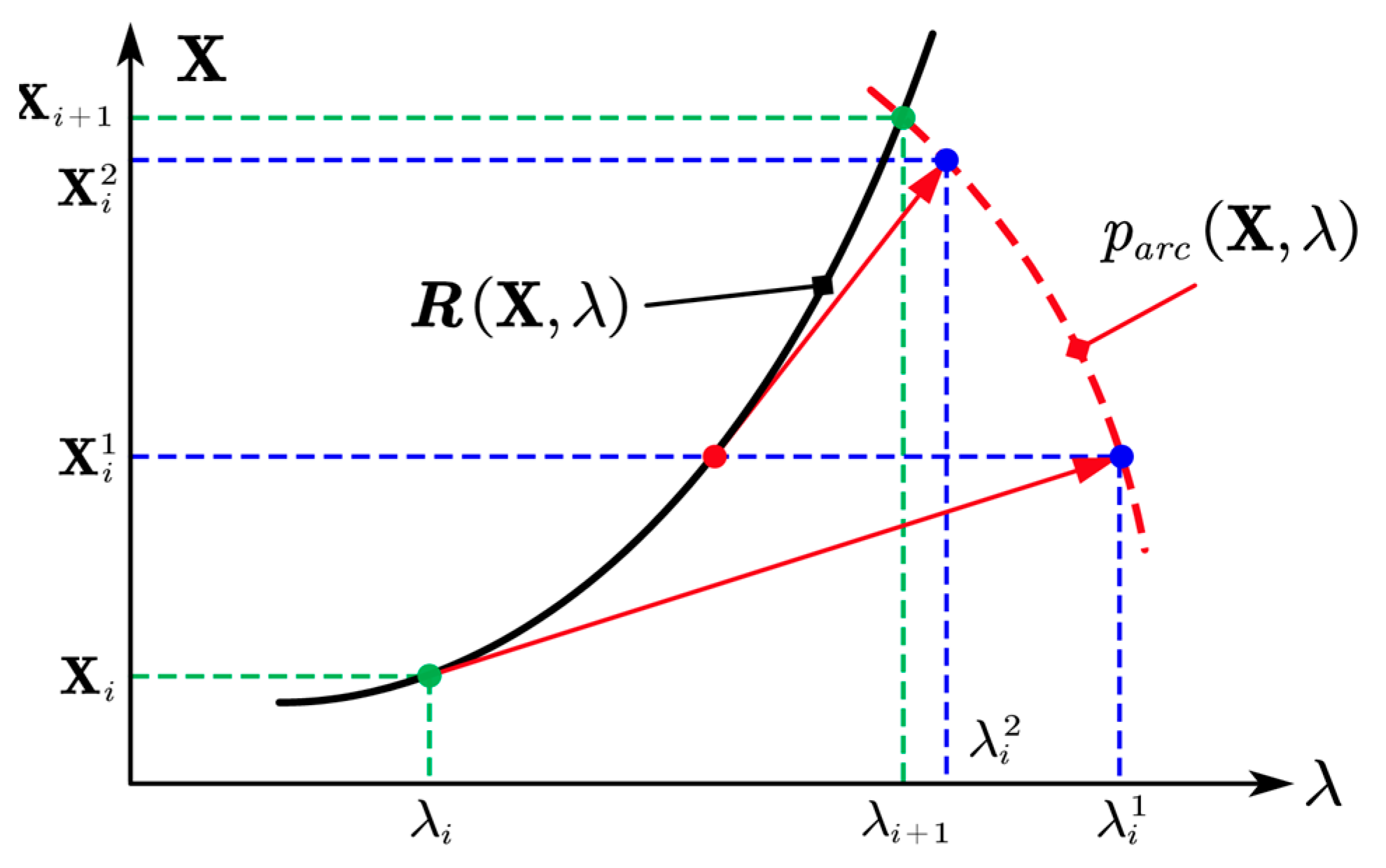
Nonlinear systems (such as the Duffing oscillator [29]) exhibit solution trajectories characterized by bifurcation phenomena and turning points. Near turning points, conventional numerical iteration schemes may exhibit poor convergence characteristics or computational divergence due to substantial variations in the solution curve’s derivative structure. To overcome this turning point issue, an arc-length continuation algorithm incorporating predictor–corrector methodology [30] is adopted, which can more efficiently and accurately capture turning points by combining prediction and correction steps. By introducing a new parameter λ, the solution curve of the equation is set as follows:
Z = X ; λ ( N H + 1 ) × 1
where N H is the total number of harmonic balance equations, and λ is the continuation parameter.
In the analysis of steady-state response characteristics, the rotational speed Ω is selected as the continuation parameter. Figure 3 illustrates a schematic representation of the predictor–corrector methodology, with the computational procedure detailed below.
To avoid derivative singularities at turning points that may compromise numerical convergence, a tangent predictor method introduced by Seydel [28] is implemented. The prediction step length Z i is as follows:
f Z i k Z i = e N H + 1 s
where e N H + 1 represents a N H + 1 dimensional unit vector with the last component equal to 1. s is the defined length step size along the solution path. The Jacobian matrix for the prediction step f Z i k is given by the following:
f Z i k = R X i k X R X i k λ ( e N H ) T 0
where e N H is the transpose of an N H -dimensional unit vector, characterized by a single unity component strategically selected to ensure the full rank of f Z i k . This rank completeness guarantees the existence of a tangent vector at point X i , λ , enabling the computation of the predictor step.
The state update equation for the i-th prediction step is expressed as follows:
Z i + 1 = Z i + Z i
The numerical continuation employs an arc-length correction methodology. Given the computational complexity of exact arc-length determination, an approximation approach is implemented. The arc-length constraint equation, perpendicular to the tangent vector through point Z i 1 k , takes the form:
p a r c Z i k = Z i k Z i 1 k T Z i k Z i 1 k s 2 = 0
where i denotes the prediction step number, k represents the correction step number. The arc-length constraint equation combines with the original residual R X to form a new residual function R e x t Z i k :
R e x t Z i k = R ( X i k ) ; p a r c ( Z i k )
Using the Newton–Raphson iteration method to solve Equation (24), the correction step length Z k is expressed as follows:
Z k = J e x t Z i k 1 R e x t Z i k ,     J e x t Z i k = R X i k X R X i k λ d p a r c d X d p a r c d λ
where d p a r c d X = 2 ( X i k X i 1 k ) T , d p a r c d λ = 1 , R X i k X = P λ X i k + Q e x λ . The expressions for P λ and Q e x λ can be derived straightforwardly.
The updated expression for the k-th correction step is given by the following:
Z i k + 1 = Z i k + Z k
Convergence is determined when the norm of the residual equation is less than the convergence threshold ε e r r , set to 10−6 in this paper:
R e x t Z i k + 1 ε e r r
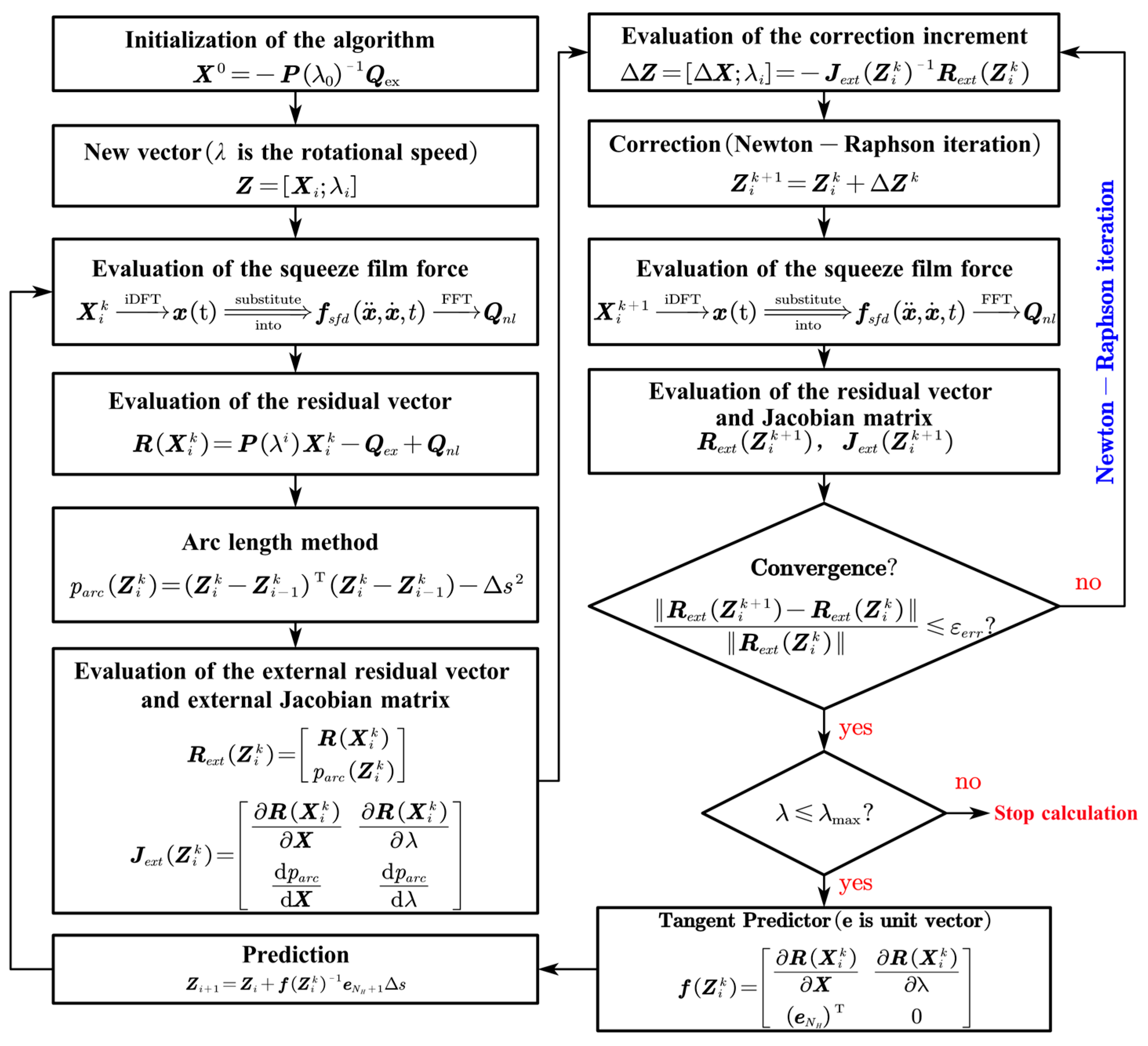
The flowchart of the HB-AFT method combined with Newton–Raphson iteration is shown in Figure 4. The calculation terminates when λ reaches λ m a x .

3.2. Stability Analysis Method

Floquet theory provides a framework for analyzing periodic solutions in linear and nonlinear systems. The stability of these periodic solutions is determined through the eigenvalues of the Floquet monodromy matrix, also known as Floquet multipliers. Based on this theory, Equation (1) can be rewritten as follows:
M s q ¨ 0 + C s Ω G s + C b a s e q ˙ 0 + K s + K b a s e q 0 = F m u + F b a s e + F s f d
where q 0 represents the periodic solution with period T and N degrees of freedom, obtainable through the HB-AFT method.
To investigate the stability of steady-state periodic solutions, a small perturbation q t is superimposed on the periodic solution q 0 t , yielding the perturbed periodic solution:
q t = q 0 t + q t
Substituting Equation (29) into Equation (28) and applying Taylor expansion around q 0 with linear approximation yields the perturbation differential equation:
M s q ¨ + ( C s Ω G + C b a s e C s f d ) q ˙ + ( K s + K b a s e K s f d ) q = 0
where K s f d = F s f d q ( q 0 , q ˙ 0 ) , C s f d = F s f d q ˙ ( q 0 , q ˙ 0 ) .
The stability of the periodic solution q 0 depends on q . Based on Floquet theory [31], one period T is divided into M equal time intervals t , assuming the monodromy matrix remains constant within each interval t . The equation can be solved through numerical integration, requiring a sufficiently large value of M . To balance computational efficiency and accuracy, M = 400 is selected. For the j-th time interval, the equation becomes:
M s q ¨ j + C j q ˙ j + K j q j = 0
where C j = C s Ω G s + C b a s e C s f d , K j = K s + K b a s e K s f d .
Primary numerical methods for approximating the monodromy matrix include the Runge–Kutta method [4], Newmark method [32], and Hsu exponential expansion method [33]. Notably, for computing the monodromy matrix of multi-degree-of-freedom finite element rotor systems, the Newmark method demonstrates superior computational efficiency [6]. Therefore, the Newmark numerical integration method is employed to solve for Floquet multipliers.
Under the Newmark scheme, the expressions for generalized velocity and acceleration of the perturbation differential equation are as follows:
q ˙ j + 1 = q ˙ j + 2 t ( q j + 1 q j ) t q ¨ j q ¨ j + 1 = q ¨ j + 4 t 2 ( q j + 1 q j t q ˙ j )
Substituting Equation (32) into Equation (31) yields:
D j q j + 1 = M s q ¨ j + 4 q ˙ j t + 4 q j t 2 + C j + 1 t q ¨ j + q ˙ j + 2 q j t
where D j = 4 M s t 2 + 2 C j + 1 t + K j + 1 . The equation can be further transformed into the following:
D j q j + 1 = t C j + 1 q ¨ j + 4 M s t 2 + C j + 1 C j q ˙ j + 4 M s t 2 + 2 C j + 1 t K j q j
For a sufficiently small time interval t , the first term on the right-hand side of Equation (34) vanishes, yielding the following:
q j + 1 = E j q ˙ j + F j q j
where E j = D j 1 4 M s t 2 + C j + 1 C j , F j = D j 1 4 M s t 2 + 2 C j + 1 t K j .
This second-order differential equation can be transformed into a system of first-order differential equations using state–space representation:
x j + 1 = T j x j
where x j = q j , q ˙ j T , T j = 2 t E j I 2 t ( F j I ) E j F j .
The Floquet monodromy matrix can then be expressed through multiplication:
Φ = T K T j + 1 T j T j 1 T 0
The stability condition for periodic solutions requires all eigenvalues u i i = 1 , 2 , . . . , 2 N of the Floquet monodromy matrix Φ to lie within the unit circle in the complex plane, meaning the magnitude of the maximum Floquet multiplier u m a x must be less than 1:
u i = R e u i 2 + I m u i 2 < 1 , i = 1,2 , 3 . . . , 2 N
Based on how Floquet multipliers cross the unit circle, as shown in Figure 5, three instability types exist [28]:
  • If Floquet multipliers cross the unit circle at (1, 0), the system’s periodic response may undergo saddle–node bifurcation.
  • If Floquet multipliers cross the unit circle at (−1, 0), the periodic response undergoes period-doubling bifurcation.
  • If a pair of complex conjugate Floquet multipliers leaves the unit circle, the periodic response undergoes secondary Hopf bifurcation.

3.3. Method Verification

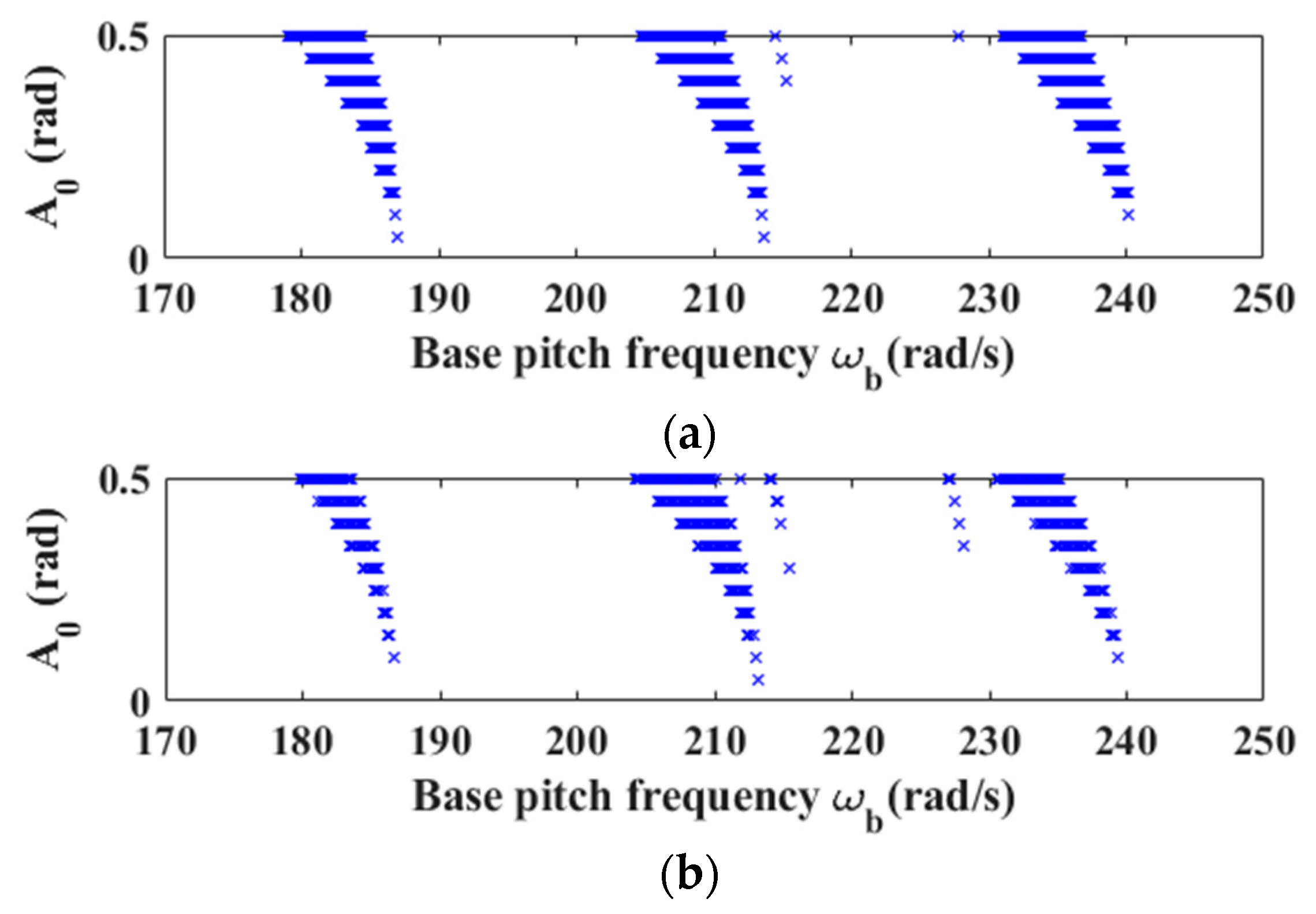
To validate the reliability of the proposed base motion rotor model and its stability analysis method, a linear single-disk rotor system, originally established by Duchemin [34] and subsequently analyzed for stability by Han and Chu [35], is selected as a comparative case study. The comparative analysis is conducted under operating conditions with rotor speed Ω = 250   r a d / s and base pitching harmonic motion angular velocity ω b y = A 0 ω b s i n ω b t r a d / s , where ω b represents the base harmonic motion frequency. Figure 6 presents a comparison of stability diagrams obtained through both methods, where the blue-shaded regions denote zones of system instability. The results demonstrate that the unstable regions predicted by the present method show excellent agreement with the literature results, both exhibiting three primary unstable zones. Minor discrepancies between the two methods primarily stem from different theoretical approaches in shaft modeling: the literature employs Euler beam theory, whereas the present study incorporates shear deformation through Timoshenko beam theory. The comparative validation confirms the reliability of the established base motion rotor dynamics model and its stability analysis method while additionally accounting for shear effects.
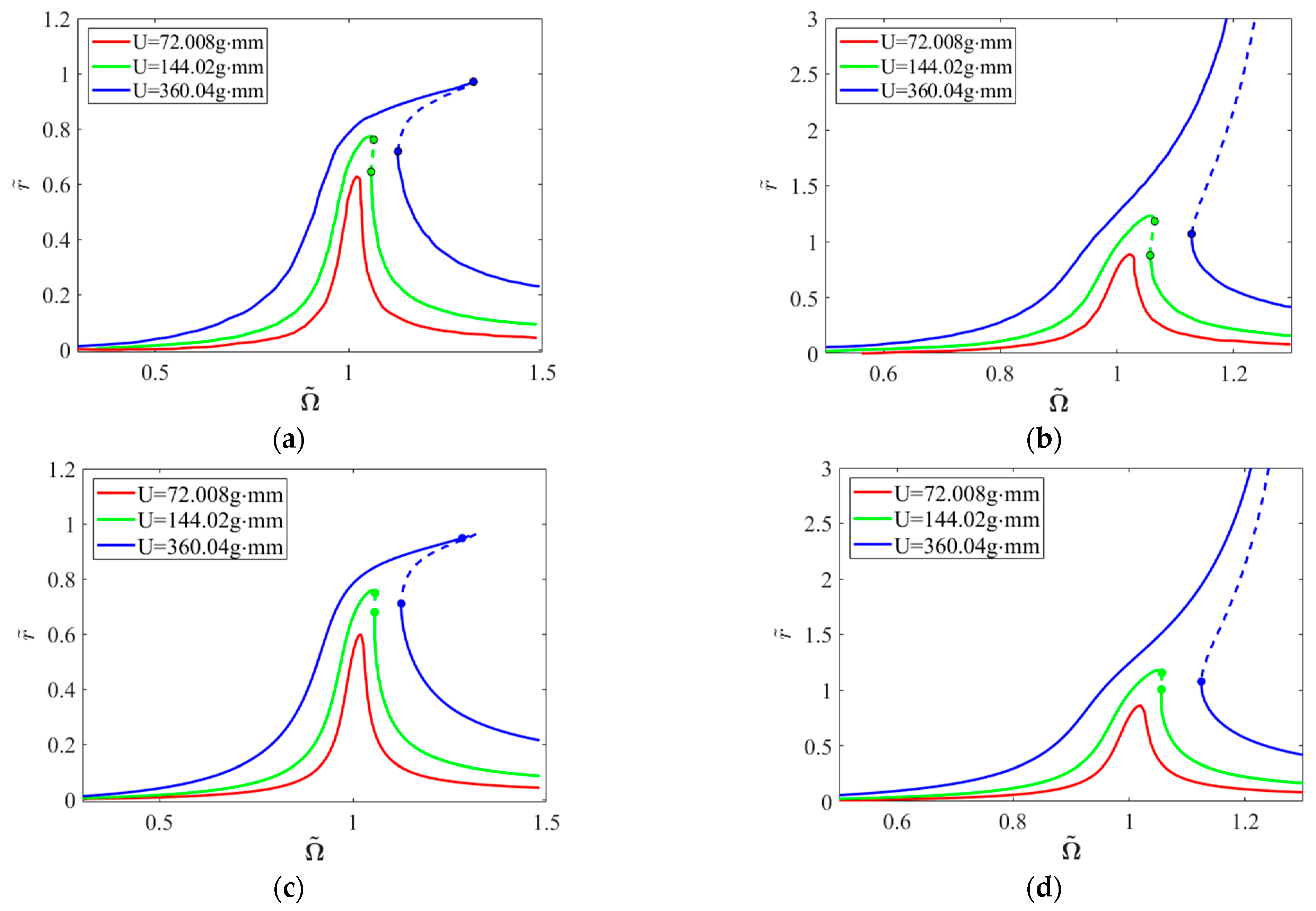
To further validate the accuracy of the HB-AFT method, Newmark-based Floquet multiplier solution method, and flexible rotor model with SFD employed in this paper, a comparison is made with Han’s [27] research findings on the dynamic characteristics and stability of a single-disk rotor system with centralized SFD on a fixed foundation. Figure 7 presents the dimensionless frequency–response amplitudes and stability curves at the SFD node and disk node under three unbalanced excitation conditions, where solid and dashed lines represent stable and unstable periodic solutions, respectively. The computational results demonstrate excellent agreement with the frequency–response characteristics reported in the literature [27].
As shown in Figure 7, the system response with a mass unbalance of 72.008 g·mm demonstrates complete stability throughout the analyzed speed range, with no bifurcation points or stability transitions detected. For cases with mass unbalances of 144.02 g·mm and 360.04 g·mm, Table 1 presents a comparison between the bifurcation points and corresponding maximum Floquet multiplier values calculated using the present model and those reported in the literature [27]. According to Floquet theory, saddle–node bifurcation occurs when Floquet multipliers cross the unit circle at (1, 0). The comparative results demonstrate good agreement in both the rotational speeds at bifurcation points and the way maximum Floquet multipliers traverse the unit circle. Discrepancies between the computational results from the two methods may be attributed to differences in finite element nodal discretization and solution methodologies (IHB combined with the Hsu method employed in the literature, while HB-AFT combined with the Newmark method is utilized in the present paper). The comparative validation confirms the reliability of the nonlinear rotor model and stability analysis method adopted in this paper.

4. Results and Discussion

A modified rotor model based on the framework presented in [27] is implemented to investigate the dynamic response characteristics and stability behavior under base motion excitation. As shown in Figure 8, the rotor model consists of an offset disk rotor system. The system incorporates a SFD with centralized elastic support at the left bearing position, while the right bearing position utilizes linear elastic support.
The primary structural parameters of the rotor system are as follows: the shaft has a total length of 0.5994 m, with an inner and outer radius of 20.65 mm and 30.15 mm, respectively. The offset disk is positioned at L / 3 distance from the left support, with an inner and outer radius of 30.15 mm and 101.6 mm, respectively, and a thickness of 50.8 mm. The rotor system is constructed from a single material with the density ρ = 7810   k g / m 3 , elastic modulus E = 211   G P a , and shear modulus G = 81.783   G P a . In the finite element model, the shaft is uniformly divided into 20 elements with 21 nodes, where SFD is located at node 1, and the disk element is positioned at node 8. The primary parameters of the SFD are listed in Table 2, where oil viscosity μ and oil clearance C are fixed parameters, while the film length   L s f d is determined by the length-to-diameter ratio L s f d / D . The eccentricity of the unbalanced mass at the disk node is denoted by U .
Setting the harmonic order as H = 3, modal analysis reveals the first two critical speeds of the rotor system as Ω 1 X = 811.3   r a d / s and Ω 2 X = 811.3 , 2784.6   r a d / s . The system response is characterized through dimensionless parameters: the dimensionless speed is expressed as Ω ~ = Ω / Ω 1 X , and the normalized displacement components in horizontal and vertical directions are denoted as y ~ = y / C , z ~ = z / C , respectively. The dimensionless deflection is defined as r ~ = y 2 + z 2 / C . Given that base pitching and yawing motions induce speed-dependent static displacement at the SFD node, the analysis focuses exclusively on the first-mode response. The investigation examines the normalized displacement amplitudes at both SFD and disk nodes, with characteristic amplitudes determined from the half-peak values of each harmonic component, excluding the static (zero-order) term.
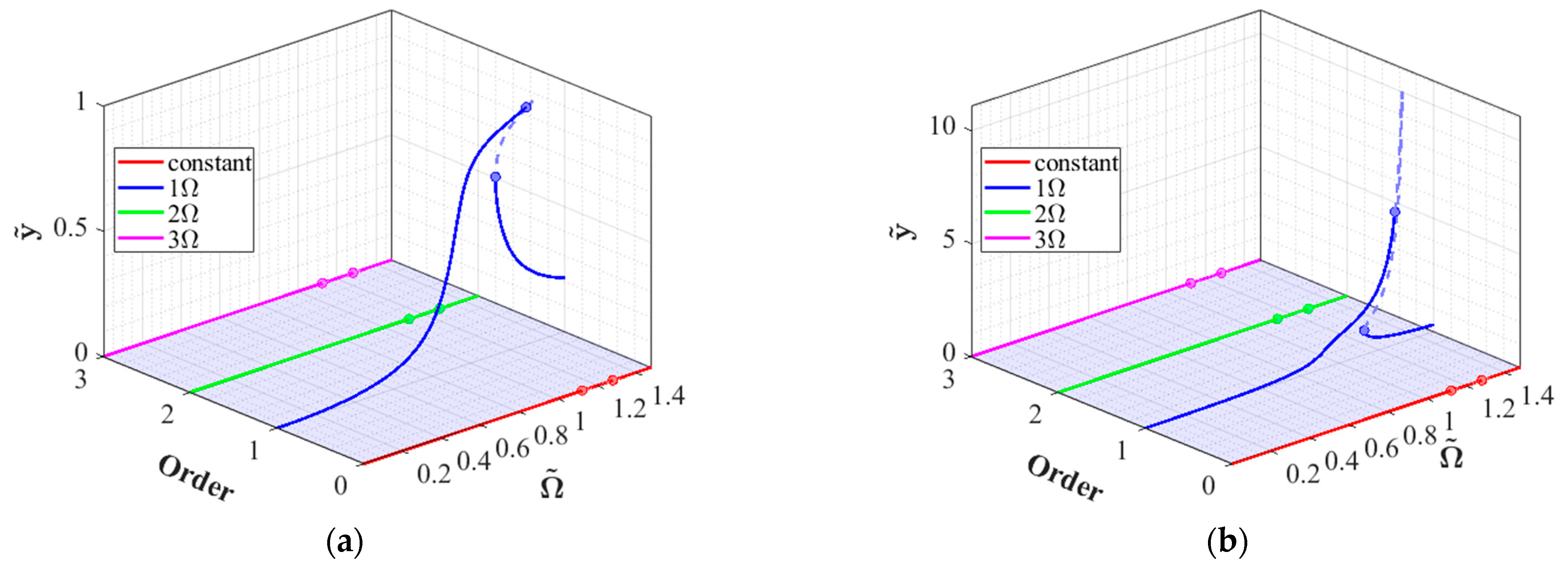
Figure 9 illustrates the harmonic response curves in the horizontal direction at both SFD and disk nodes under fixed base conditions, with a clearance-to-radius ratio of C / R = 0.485 % and unbalanced magnitude of U = 360.04   g m m . Unstable solutions are denoted by dashed lines. At bifurcation points, the system exhibits characteristic saddle–node bifurcation behavior: minor perturbations may trigger state transitions from unstable to other stable solutions. This jump phenomenon is attributed to the hardening spring characteristics of the SFD [8], where nonlinear oil film stiffness increases with amplitude. Under fixed base conditions, the system response is dominated by the fundamental frequency component Ω , with negligible contributions from higher harmonic components 2 Ω and 3 Ω , indicating that the jump phenomenon is primarily governed by the fundamental frequency response under unbalanced excitation.

4.1. Effects of Base Motions

In this section, a clearance-to-radius ratio of C / R = 0.485 % and an unbalanced parameter of U = 144.02   g m m are selected.

4.1.1. Base Rolling Motion

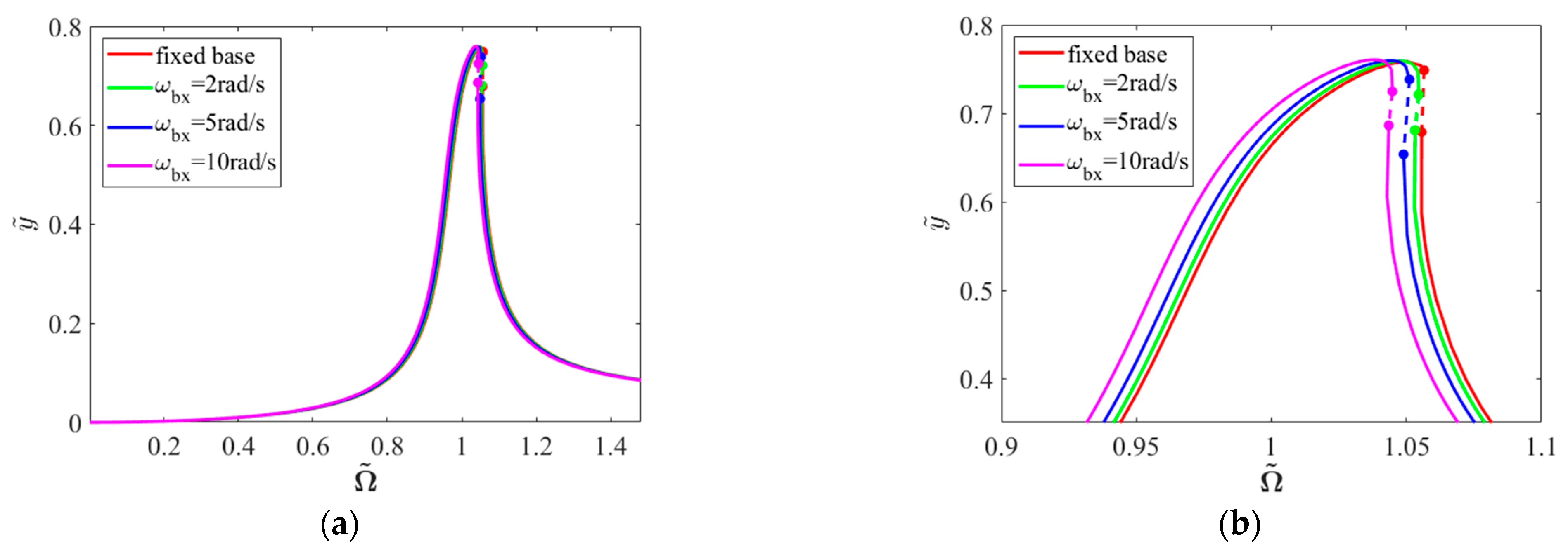
Figure 10 illustrates the frequency–response characteristics in the horizontal direction at SFD and disk nodes under various base rolling angular velocities, with unstable solutions indicated by dashed lines. Analysis of primary resonance behavior demonstrates that the base rolling angular velocity exhibits minimal influence on the amplitude of resonance peaks, with the system maintaining hardening characteristics. When the base rolling angular velocity is co-directional with rotor rotation, a slight frequency downshift of the resonance peak occurs with increasing base rolling speed. According to Equation (3), this phenomenon can be attributed to the modification of system natural frequencies through the additional stiffness terms induced by base rolling motion.
Figure 11 illustrates the spectral composition of frequency–response characteristics in the horizontal direction at both SFD and disk nodes under a prescribed base rolling angular velocity ω b x = 10   r a d / s . The results indicate that the responses at both nodes remain dominated by the fundamental frequency component Ω , with negligible superharmonic contributions 2 Ω and 3 Ω . This frequency composition indicates that the introduction of base rolling motion preserves the intrinsic nonlinear characteristics of the SFD, maintaining the predominance of the fundamental frequency response.

4.1.2. Base Pitching Motion

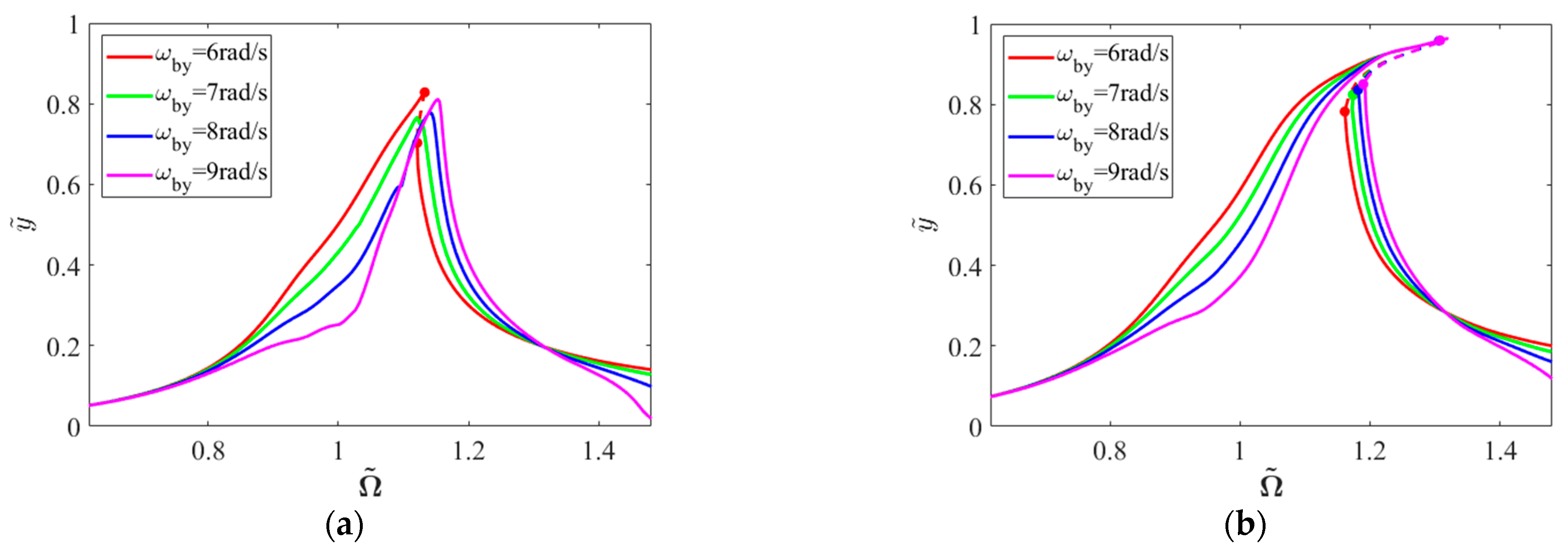
Figure 12 illustrates the frequency–response curves at SFD and disk nodes under various base pitching angular velocities. The results demonstrate that with increasing pitching velocity, the deflection at the SFD node shows an overall upward trend. According to Equation (4), the inertial moment term Ω J i p ω b y introduced by base pitching motion increases with rotational speed, leading to additional displacement in the system. The amplitude at the critical position of the disk node exhibits characteristics of an initial increase followed by a decrease. At ω b y = 2   r a d / s , the bifurcation points near the resonance peak remain saddle–node bifurcation points. When ω b y increases to 4 rad/s, the bistable phenomenon in the solution curves disappears, and the system hardening spring characteristics are suppressed. As the pitching angular velocity increases to 9 rad/s, the primary resonance peak at the disk node significantly decreases, but a secondary resonance peak emerges in the high-speed region Ω ~ > 1.3 . This phenomenon indicates that under conditions of relatively small mass unbalance, appropriate base pitching angular velocity can improve the system bifurcation characteristics and enhance dynamic stability. However, excessive base pitching angular velocity can lead to significant static offset in the high-speed region and may even generate secondary resonance phenomena.
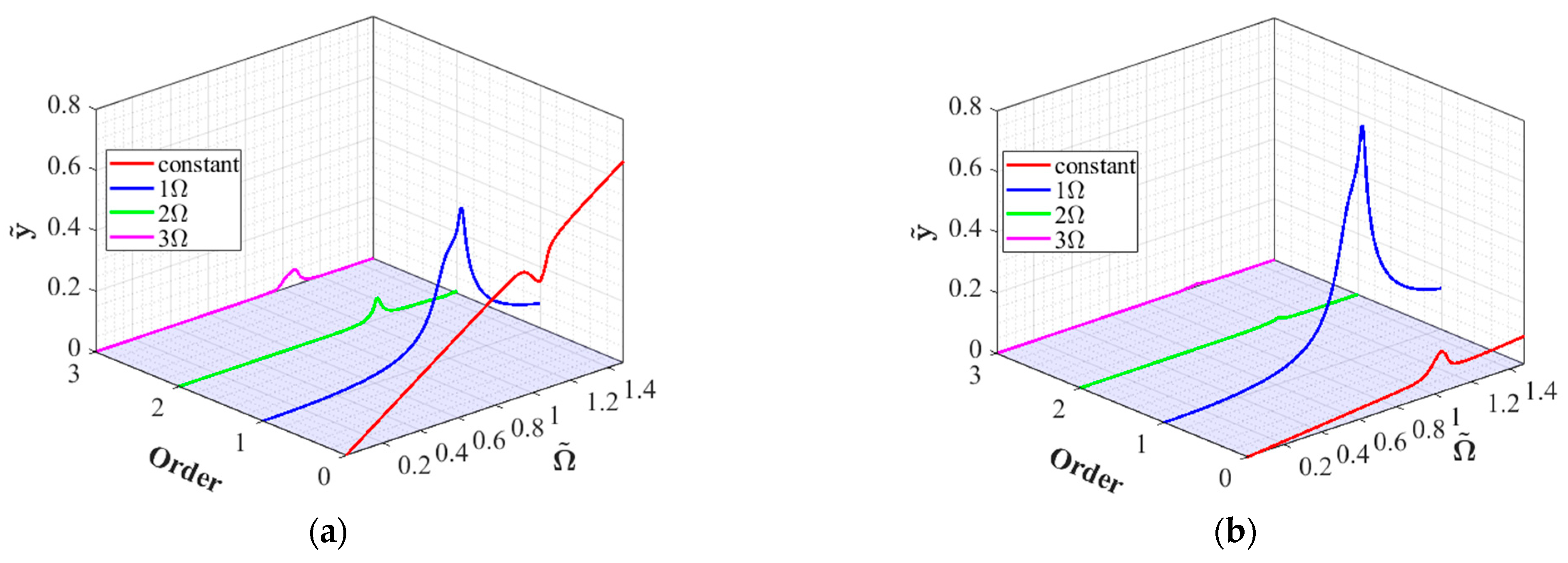
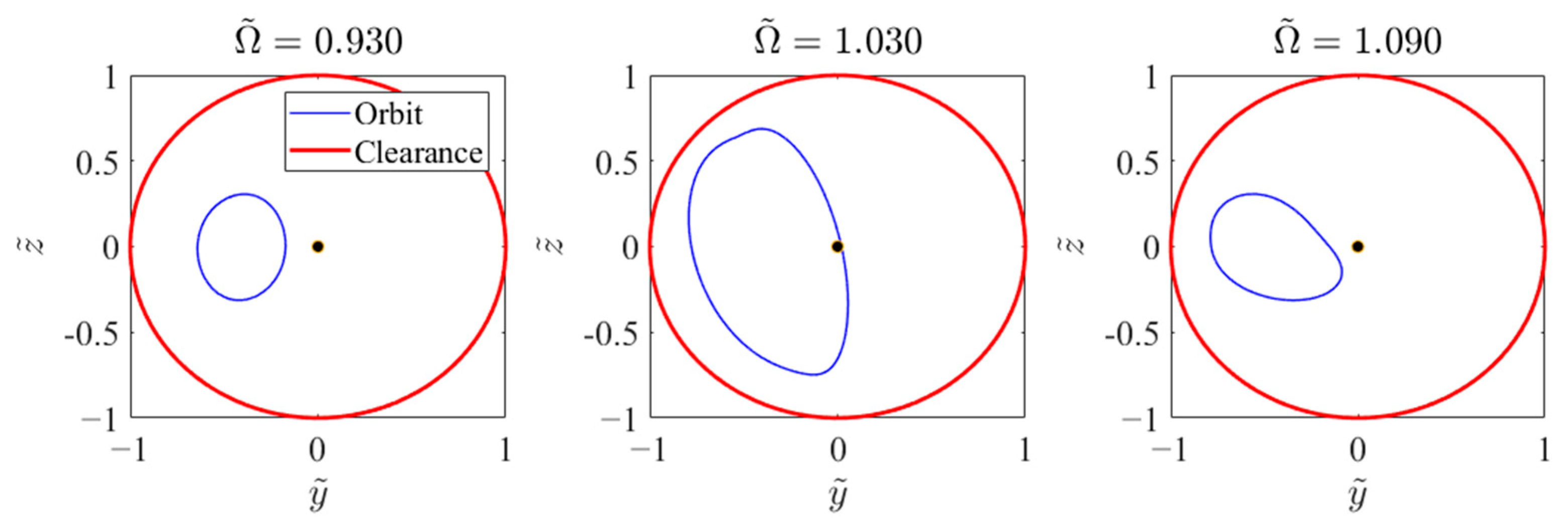
Figure 13 demonstrates the frequency–response characteristics of various harmonic components when the base pitching angular velocity is ω b y = 6   r a d / s . Analysis results indicate that the horizontal response at the SFD node contains static displacement components, fundamental frequency component Ω , and higher harmonic components 2 Ω and 3 Ω , with static displacement and fundamental frequency Ω components being dominant. The disk node response is primarily governed by the constant term and fundamental frequency component Ω , with the static displacement component exhibiting a notable peak characteristic near the critical speed. The static displacement component at the SFD node generally increases with rotational speed but shows a slight decrease near the critical speed. This phenomenon is further validated by the journal orbit at the SFD node, shown in Figure 14: when the speed approaches the critical speed ( Ω ~ = 1.03 ), despite the significantly enlarged orbit, its center is positioned closer to the bearing center. This dynamic characteristic is similar to the self-centering effect observed in rotor systems with static eccentricity SFD [7].
To better observe the secondary resonance phenomenon at the disk node, Figure 15 presents the frequency–response curves of various harmonic components in the horizontal direction under different pitching angular velocities. At a pitching angular velocity of 8 rad/s, the synchronous frequency–response curve exhibits a single distinct peak at Ω ~ = 1.09 . When the pitching angular velocity increases to 9 rad/s, this primary peak amplitude decreases, and a secondary peak emerges at Ω ~ = 1.40 . Upon further increasing the pitching angular velocity to 10 rad/s, the primary peak continues to decrease while the secondary peak amplitude increases, making the dual-peak phenomenon more pronounced. This phenomenon can be attributed to the large static eccentricity induced at high rotational speeds under base pitching motion. The significant static eccentricity intensifies the nonlinear characteristics of the oil film stiffness, subsequently altering the system’s intrinsic modal properties.

4.1.3. Base Yawing Motion

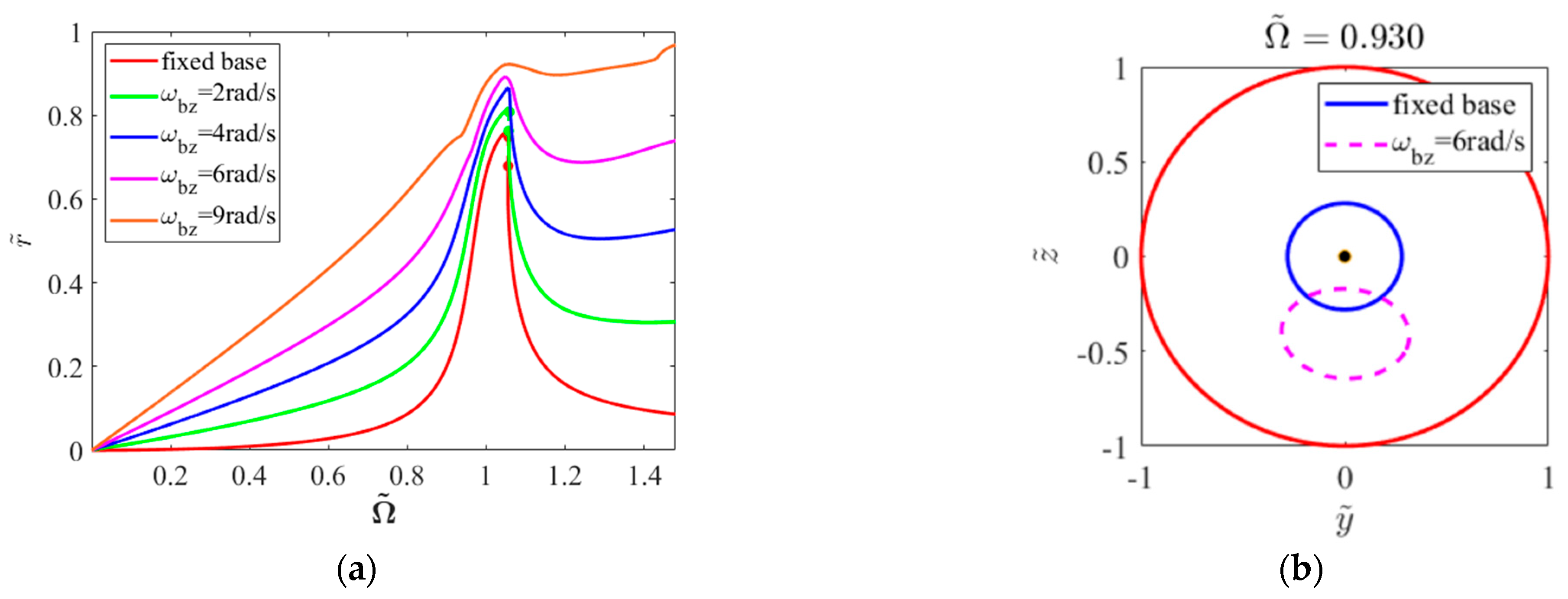
Figure 16a shows the frequency–response characteristics of deflection at the SFD node under base yawing motion. The results indicate that yawing motion leads to increased vibration amplitude at the SFD node, primarily due to the influence of the inertial moment term Ω J i p ω b z introduced by base yawing motion. Comparing Figure 16a with Figure 12a reveals that under identical angular velocities, neglecting gravity effects, yawing and pitching motions have identical impacts on the deflection at the SFD node. The identical response characteristics result from the equivalent magnitudes of inertial moments induced by both motions orthogonal to the rotation axis, only distinguished by their action planes. As observed from the rotor trajectories shown in Figure 16b, under yawing motion, the journal center exhibits a static offset in the negative z direction.

4.2. Effects of Mass Unbalance

In this section, the clearance-to-radius ratio C / R is set at 0.485 % . To thoroughly investigate the influence mechanism of base motion on the rotor system under deteriorating unbalanced conditions, two unbalanced values are selected: 252   g m m and 360.04   g m m . Given that base motion may excite higher-order responses under large unbalanced conditions, the harmonic order is set to H = 8 to ensure computational accuracy.
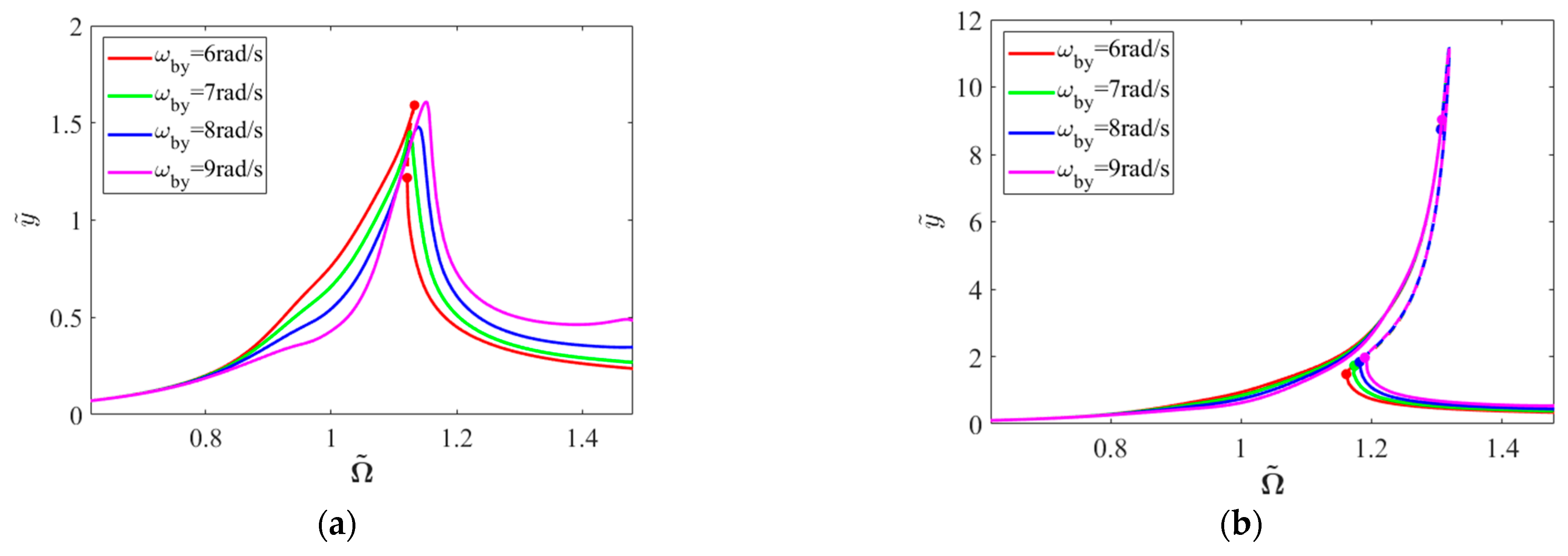
The frequency–response characteristics at the SFD node and the disk node under base pitching motion are presented in Figure 17 and Figure 18, where unstable solutions are denoted by dashed lines. With the increase of pitching angular velocity from 6 rad/s to 9 rad/s, a slight shift of the resonance peak toward higher frequencies is observed. Under moderate unbalance ( U = 252   g m m ), unstable solutions persist at a pitching angular velocity of 6 rad/s, which are identified as saddle–node bifurcation points through Floquet multiplier analysis. These unstable solutions completely vanish when the pitching angular velocity reaches 7 rad/s. In contrast, under large unbalanced conditions ( U = 360.04   g m m ), the bifurcation type remains consistently characterized as saddle–node bifurcation, with only a reduction observed in the rotational speed range exhibiting bistable behavior phenomenon.
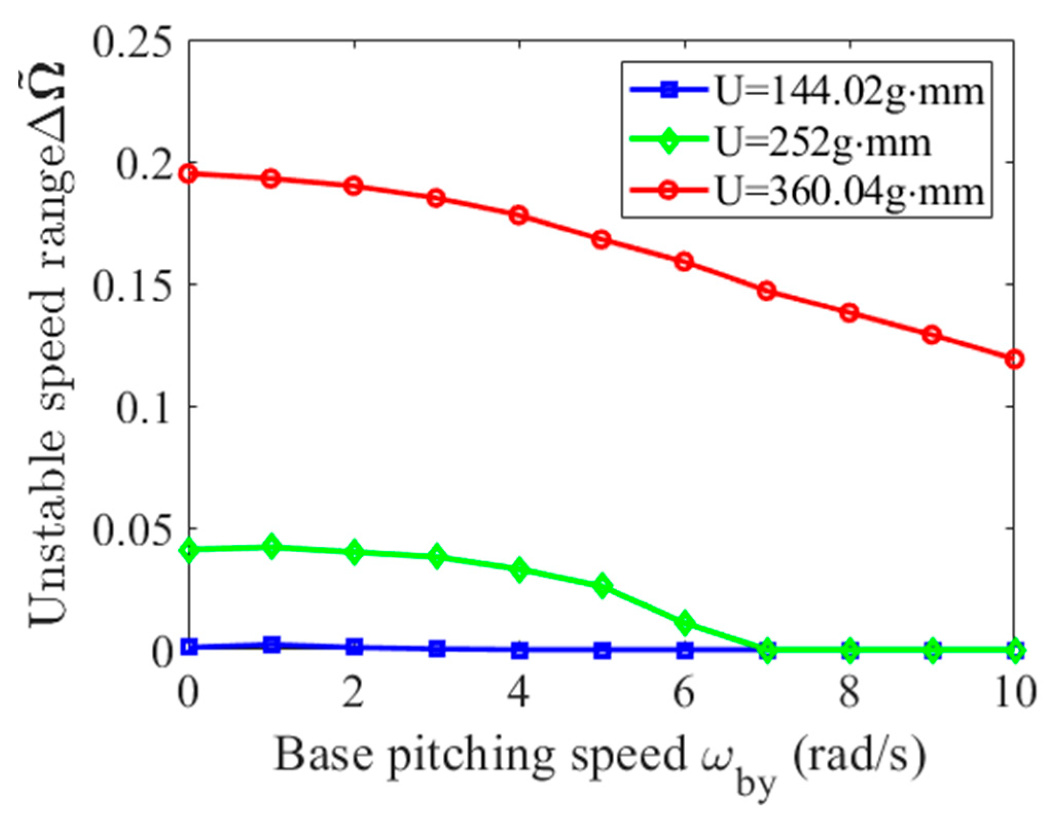
Figure 19 quantitatively illustrates the variation trends of the instability region ( Ω ~ ) with respect to pitching angular velocity under different unbalanced conditions. For U = 144.02   g m m , the instability region is minimal under fixed base conditions and completely disappears when the pitching angular velocity increases to 4 rad/s. At U = 252   g m m , the initial instability region exhibits Ω ~ = 0.041 and gradually diminishes with increasing pitching angular velocity, ultimately vanishing when the pitching angular velocity reaches 7 rad/s. For U = 360.04   g m m , the initial instability region demonstrates Ω ~ = 0.195 and exhibits an approximately linear decreasing trend with increasing pitching angular velocity, maintaining an unstable region of Ω ~ = 0.119 even at 10 rad/s.
These observations indicate that base pitching motion generally enhances system stability; however, its suppression effectiveness demonstrates a distinct unbalanced threshold characteristic. At lower unbalanced magnitudes, the bistable behavior can be completely suppressed through moderate base pitching excitation. As the unbalanced magnitude increases, the instability region expands significantly, requiring correspondingly higher pitching angular velocities for effective suppression.
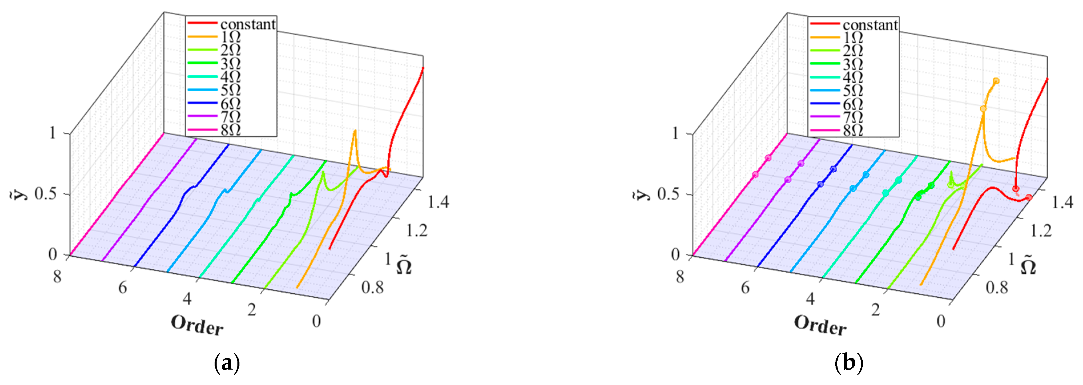
Figure 20 presents the frequency–response curves of horizontal displacement at the SFD node under a base pitching angular velocity ω b y = 9   r a d / s for different unbalanced magnitudes. The three-dimensional spectral plots reveal varying degrees of change in the response amplitudes across different order components as the rotational speed increases. Under the unbalanced magnitude of U = 252   g m m , the system response exhibits predominantly constant terms and 1 ~ 2 Ω components, accompanied by minor higher-order harmonic components of 4 ~ 6 Ω , while the 7 ~ 8 Ω harmonic components remain negligible. Under the larger unbalanced magnitude of U = 360.04   g m m , the fundamental frequency component demonstrates significantly increased amplitude, whereas the 4 ~ 8 Ω components become negligible. The constant term (static offset) shows a substantial reduction near the resonance peak. At Ω ~ = 1.25 , the dimensionless amplitude of the constant term approaches zero, indicating enhanced self-centering effects of the SFD under large unbalanced conditions. In the resonance region, the system response is predominantly governed by the fundamental frequency response, with relatively minor contributions from higher-order harmonic components.

4.3. Effects of SFD Parameters

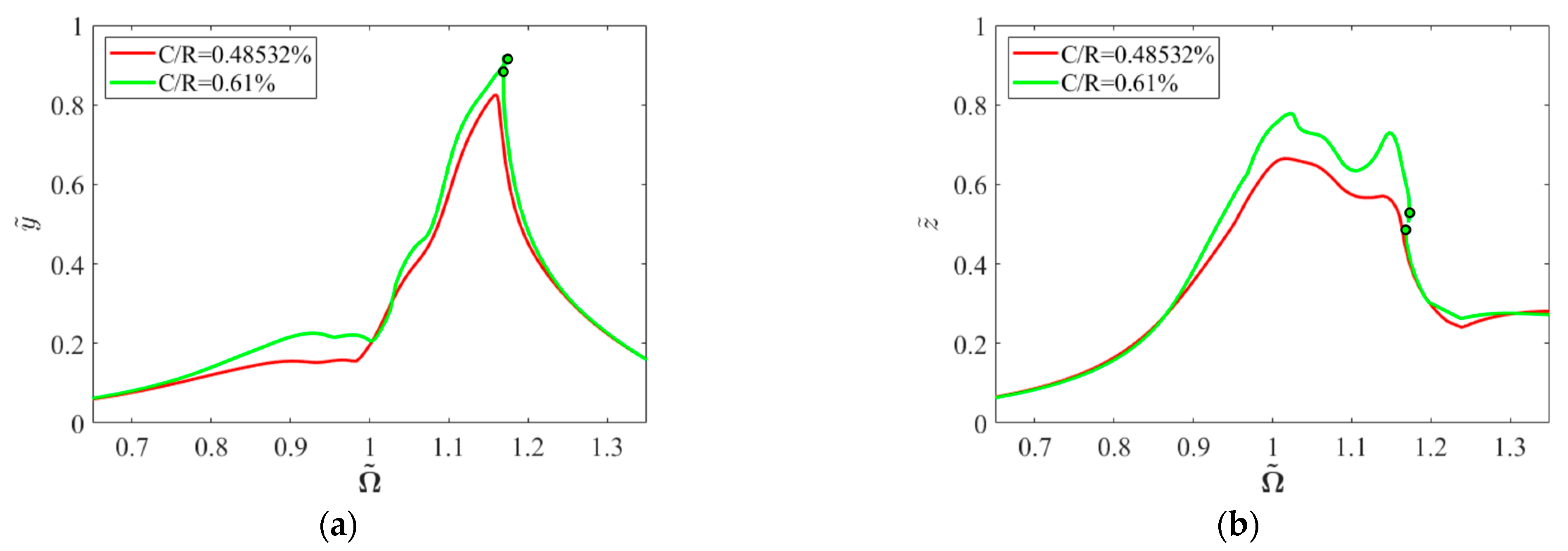
To investigate the influence of squeeze film damper parameters on system instability, analyses were conducted with fixed unbalanced magnitude U = 252   g m m and pitching angular velocity ω b y = 10   r a d / s , to investigate the effects of varying clearance-to-radius ratios ( C / R ) on the system frequency–response characteristics. Figure 21 illustrates the frequency–response curves at the SFD node under C / R = 0.485 % and 0.61 % , where circle markers denote saddle–node bifurcation points.
The results indicate that at C / R = 0.485 % , the system maintains stable motion within the specified speed range. When C / R increases to 0.61 % , although the frequency–response curves in both horizontal and vertical directions exhibit trends similar to those at C / R = 0.485 % , enhanced nonlinear effects lead to the emergence of unstable solutions. Floquet multiplier analysis identifies these instability points as saddle–node bifurcations, resulting in the reappearance of bistable characteristics in the system.
Figure 22 presents the frequency–response curves at the SFD node when C / R increases to 0.728 % , where circle markers indicate saddle–node bifurcation points and triangular markers denote secondary Hopf bifurcation points. Multiple unstable solution segments appear on the periodic solution curve, with Table 3 detailing the characteristic variations of Floquet multipliers at bifurcation points.
For the unstable region A-B, a saddle–node bifurcation occurs at point A, while at point B, Floquet multipliers cross the unit circle as complex conjugate pairs, indicating a secondary Hopf bifurcation. This bifurcation suggests the loss of stability in periodic solutions near this rotational speed, leading to quasi-periodic motion. Regions C-D and E-F exhibit hardening spring characteristics, indicating the potential occurrence of complex jump phenomena near the bifurcation points.
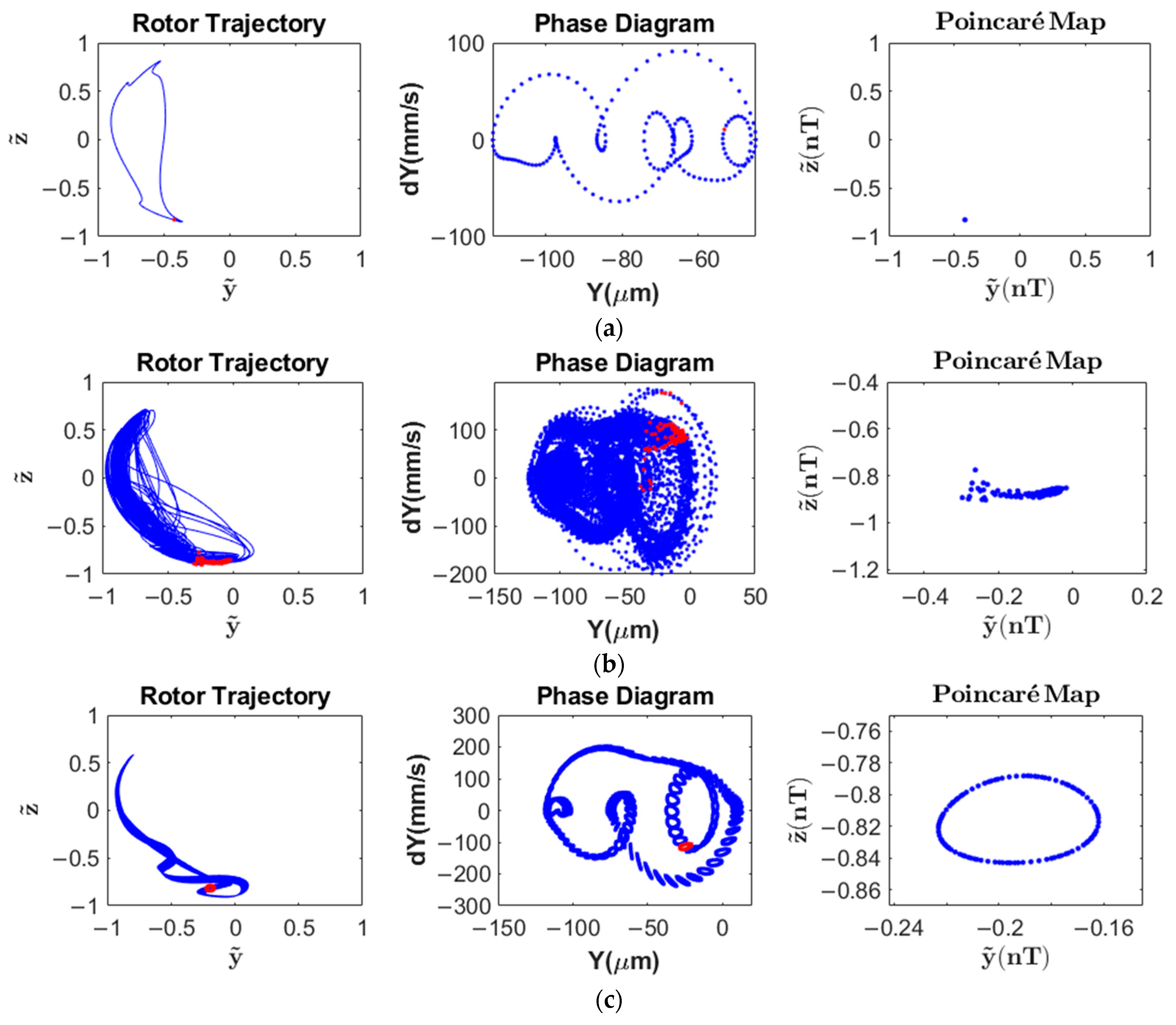
Since the harmonic balance method approximates system motion through finite harmonic terms truncation, it can only yield periodic solutions. To verify the existence of non-periodic solutions within specific speed ranges, time–domain analysis was conducted using the Newmark numerical integration method [17] with a time step corresponding to 1/200 of the period. To ensure computational convergence, calculations extended over 2000 periods at each investigated rotational speed, with the final 100 periods used to construct Poincaré sections. All simulations were initialized with a uniform nodal displacement of y = 1 μm.
Figure 23 illustrates the rotor trajectories, phase diagrams, and Poincaré sections at the SFD node for various rotational speeds. At Ω ~ = 1.025 , the system exhibits stable period-1 motion. At Ω ~ = 1.05 , the phase space trajectory demonstrates irregular evolution with scattered points in the Poincaré section, indicating the possible chaotic motion. At Ω ~ = 1.075 , the system displays quasi-periodic motion with a complete toroidal structure in the Poincaré section. At Ω ~ = 1.10 , despite intersecting rotor trajectory, the Poincaré section shows a single point, indicating a return to period-1 motion. The time–domain computational results validate the harmonic balance method’s predictions regarding non-periodic solutions.
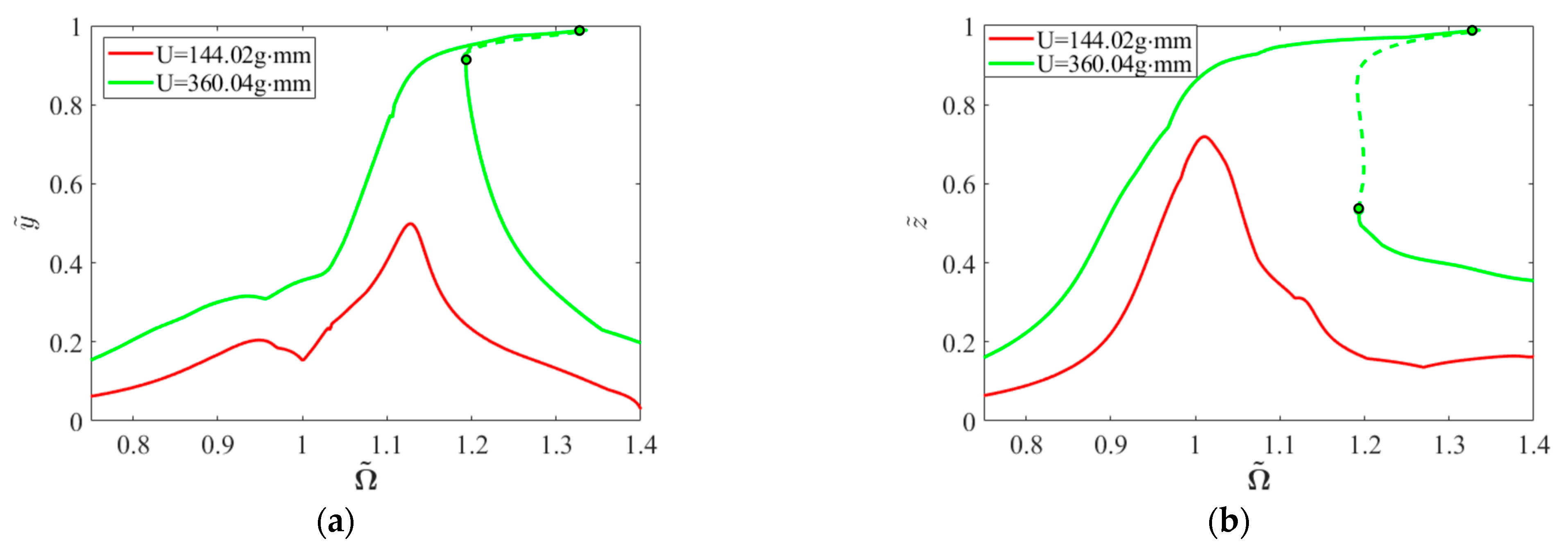
Figure 24 illustrates the frequency–response curves at the SFD node under fixed conditions of clearance-to-radius ratio C / R = 0.728 % and base pitching angular velocity ω b y = 10   r a d / s , with varying unbalanced magnitudes of U = 144.02   g m m and 360.04   g m m . Circle markers in the figure denote saddle–node bifurcation points.
Analysis reveals distinct dynamic behaviors across different unbalanced magnitudes. At lower unbalanced magnitudes, the system exhibits single-valued stable responses without bifurcation phenomena or unstable solutions. When the unbalanced magnitude increases to 252   g m m (shown in Figure 22), multiple regions of unstable solutions emerge, characterized by both secondary Hopf bifurcations and saddle–node bifurcations. Further increase in unbalanced magnitude to 360.04   g m m results in a region of unstable solution, which Floquet multiplier analysis identifies as a saddle–node bifurcation. This significant variation in dynamic behavior demonstrates the crucial influence of unbalanced magnitude on system bifurcation characteristics, indicating that specific parameter combinations can lead to fundamentally different bifurcation patterns.

5. Conclusions

This study establishes equations of motion for a single-rotor system with a centralized squeeze film damper under base motion excitation using the finite element method. The periodic solutions were obtained using the HB-AFT method with arc-length continuation. Bifurcation patterns were identified through Floquet multiplier analysis combined with the Newmark method, while non-periodic solutions were verified using Newmark numerical integration, ensuring result reliability. The following nonlinear dynamic phenomena were observed and analyzed:
  • Under unbalanced excitation, the system exhibits saddle–node bifurcations accompanied by jump phenomena, with response spectra confined to synchronous components. Under base rolling motion, the system maintains hardening characteristics, with frequency–response curves shifting toward lower frequencies as rolling angular velocity increases due to additional stiffness effects. Base pitching motion significantly enhances nonlinear effects, manifesting as higher-order harmonic components 2 Ω , 3 Ω in the response. The inertial moment introduced by pitching motion induces horizontal static eccentricity. In the absence of gravitational effects, base yawing motion produces vertical static eccentricity with effects comparable to pitching motion.
  • Increasing unbalanced magnitude significantly expands the unstable speed range, with more pronounced centering phenomena near critical speeds. Conversely, increasing pitching angular velocity progressively reduces the unstable speed range. At lower unbalanced magnitudes, strategic implementation of pitching motion demonstrates the capacity for the complete elimination of instability regions, validating the stabilizing influence of base pitching excitation.
  • Under specific combinations of unbalanced magnitude and base pitching angular velocity, variations in the clearance-to-radius ratio of the SFD induce complex nonlinear phenomena: secondary Hopf bifurcations manifest within specific speed ranges, resulting in destabilization of periodic solutions and transition to quasi-periodic motion, with potential progression to chaotic motion. These complex dynamic behaviors demonstrate strong coupling characteristics between system parameters and motion states.
This research presents a methodology for analyzing periodic stability in nonlinear rotor systems under base motion excitation. The findings enhance the understanding of nonlinear dynamic characteristics and motion stability in rotor-SFD-support systems under base excitation, providing theoretical foundations for dynamic parameter optimization and vibration control.

Author Contributions

Conceptualization, B.Z. and X.C.; Data curation, X.C.; Formal analysis, B.Z.; Funding acquisition, X.C.; Investigation, B.Z., X.C. and F.X.; Methodology, B.Z., X.C. and F.X.; Project administration, X.C., G.R. and X.G.; Resources, X.C., G.R. and X.G.; Supervision, X.C., G.R. and X.G.; Validation, B.Z., X.C. and F.X.; Visualization, B.Z. and F.X.; Writing—original draft, B.Z.; Writing—review and editing, X.C. All authors have read and agreed to the published version of the manuscript.

Funding

This research was funded by [the National Natural Science Foundation of China] grant number 12302066, [the National Science and Technology Major Project] grant number [J2022-IV-0004-0021], [the Basic and Applied Basic Research Foundation of Guangdong Province] grant number [2022A1515110077], and [the Shenzhen Stability Support Program for Higher Education] grant number [20220815113550002] And The APC was funded by [20220815113550002].

Data Availability Statement

The data presented in this study are available on request from the corresponding author.

Acknowledgments

The authors are grateful for the support from the Young Elite Scientists Sponsorship Program (YESS) by the China Association for Science and Technology (CAST). This research is also technically supported by the Center for Computational Science and Engineering at Southern University of Science and Technology.

Conflicts of Interest

The authors declare no conflicts of interest.

List of Nomenclature

AbbreviationDefinition
SFDsqueeze film damper
HB- AFTharmonic balance method with alternating frequency/time technique
IHBincremental harmonic balance method
IDFTinverse discrete Fourier transform
DFTdiscrete Fourier transform
List of symbols
SymbolDefinition
x 0 , y 0 , z 0 base translational displacement projected onto O x y z
ω b x , ω b y , ω b z angular velocities for base rolling, pitching, and yawing motions about the O x , O y , and O z axis
q , q , q ¨ generalized displacement, velocity, and acceleration of the rotor system
M s , C s , G , K s mass, damping, gyroscopic, and stiffness matrices of the rotor system
Ω rotor speed
C b a s e ,   K b a s e damping and stiffness matrices introduced by base motions
F m u unbalanced force
F b a s e inertial force introduced by base motions
F s f d nonlinear oil film force induced by SFD
m i , J i p , J i d mass, polar moment of inertia, and diametral moment of inertia of the i-th disk element
x d axial position of the disk
F m u , c ,   F m u , s cosine and sine components of the unbalanced force
m m u , e m u , η mass, eccentricity, and phase angle of the mass unbalance
p , h pressure and thickness of the oil film
θ circumferential coordinate beginning on the line connecting the bearing and journal centers
O b ,   O j centers of bearing and journal
μ ,   R , C , L s f d dynamic viscosity, radius, clearance, and axial length of the SFD
D diameter of the SFD
e journal eccentricity
ε dimensionless radial displacement of the oil film
ψ ˙ s f d journal precession angular velocity
F r , F t oil film force in tangential and radial direction
I 1 , I 2 , I 3 Sommerfeld integrals
F y ,   F z oil film force in y, z direction
a 0 ,   c 0 Constant terms for generalized displacement and nonlinear force
a j , b j j-th cosine and sine truncated Fourier terms for generalized displacement
c j , d j j-th cosine and sine truncated Fourier terms for nonlinear force
H orders of truncated Fourier series
i imaginary unit; prediction step number (subscript)
x n , x ˙ n discrete time–domain information of truncated Fourier terms for generalized displacement and velocity
N f number of selected IDFT discretization points
f ¯ n l x ˙ n , x n discrete time–domain information of truncated Fourier terms for nonlinear force
Z solution of the HB-AFT combined with continuation algorithm
λcontinuation parameter
N H number of harmonic balance equations
e N H + 1 N H + 1 dimensional unit vector with the last component equal to 1
s defined length step size along the solution path
k correction step number
f Z i k   Jacobian matrix for the i-th prediction step
R , R e x t   residual and extend residual functions for HB-AFT
Z k k-th correction step length
p a r c   arc-length constraint equation
ε e r r convergence threshold for Newton–Raphson iteration
N degrees of freedom of the rotor system
q 0 periodic solution of the rotor system
q perturbation of the periodic solution
t time interval of the Newmark method in stability analysis
C s f d ,   K s f d   linearized damping and stiffness matrices of SFD
M number of time intervals in stability analysis
Φ Floquet monodromy matrix
u i eigenvalues of the Floquet monodromy matrix i = 1 , 2 , . . . , 2 N , also called Floquet multiplier
u m a x maximum Floquet multiplier
ω b base harmonic motion frequency
Ω ~ dimensionless rotational speed
Ω 1 X , Ω 2 X first and second critical speeds of the rotor system
y ~ , z ~ normalized displacement components in horizontal and vertical directions
r ~ dimensionless deflection
U unbalanced magnitude

References

  1. Holmes, R. The Non-Linear Performance of Squeeze-Film Bearings. J. Mech. Eng. Sci. 1972, 14, 74–77. [Google Scholar] [CrossRef]
  2. Holmes, R.; Dogan, M. Investigation of a rotor bearing damper bearing assembly incorporating a squeeze-film damper bearing. J. Mech. Eng. Sci. 1982, 24, 129–137. [Google Scholar] [CrossRef]
  3. McLean, L.J.; Hahn, E.J. Unbalance Behavior of Squeeze Film Damped Multi-Mass Flexible Rotor Bearing Systems. J. Lubr. Technol. 1983, 105, 22–28. [Google Scholar] [CrossRef]
  4. Friedmann, P.P. Numerical methods for determining the stability and response of periodic systems with applications to helicopter rotor dynamics and aeroelasticity. Comput. Math. Appl. 1986, 12, 131–148. [Google Scholar] [CrossRef]
  5. Hsu, C.S. On approximating a general linear periodic system. J. Math. Anal. Appl. 1974, 45, 234–251. [Google Scholar] [CrossRef]
  6. Peletan, L.; Baguet, S.; Torkhani, M.; Jacquet-Richardet, G. A comparison of stability computational methods for periodic solution of nonlinear problems with application to rotordynamics. Nonlinear Dyn. 2013, 72, 671–682. [Google Scholar] [CrossRef]
  7. Zhao, J.; Linnett, I.; Mclean, L. Imbalance Response and Stability of Eccentric Squeeze-Film-Damped Nonlinear Rotor Bearing Systems. JSME Int. J. Ser. B 1994, 37, 886–895. [Google Scholar] [CrossRef]
  8. Zhao, J.Y.; Linnett, I.W.; McLean, L.J. Subharmonic and Quasi-Periodic Motions of an Eccentric Squeeze Film Damper-Mounted Rigid Rotor. J. Vib. Acoust. 1994, 116, 357–363. [Google Scholar] [CrossRef]
  9. Bonello, P.; Brennan, M.J.; Holmes, R. Non-Linear Modelling of Rotor Dynamic Systems with Squeeze Film Dampers—An Efficient Integrated Approach. J. Sound Vib. 2002, 249, 743–773. [Google Scholar] [CrossRef]
  10. Inayat-Hussain, J.I. Bifurcations in the response of a flexible rotor in squeeze-film dampers with retainer springs. Chaos Solitons Fractals 2009, 39, 519–532. [Google Scholar] [CrossRef]
  11. Chen, Y.; Rui, X.; Zhang, Z.; Shehzad, A. Improved incremental transfer matrix method for nonlinear rotor-bearing system. Acta Mech. Sin. 2020, 36, 1119–1132. [Google Scholar] [CrossRef]
  12. Qin, W.; Zhang, J.; Ren, X. Response and bifurcation of rotor with squeeze film damper on elastic support. Chaos Solitons Fractals 2009, 39, 188–195. [Google Scholar] [CrossRef]
  13. Chen, H.; Hou, L.; Chen, Y.; Yang, R. Dynamic characteristics of flexible rotor with squeeze film damper excited by two frequencies. Nonlinear Dyn. 2016, 87, 2463–2481. [Google Scholar] [CrossRef]
  14. Ri, K.; Jong, Y.; Yun, C.; Kim, K.; Han, P. Nonlinear vibration and stability analysis of a flexible rotor-SFDs system with cubic nonlinearity. Nonlinear Dyn. 2022, 109, 1441–1461. [Google Scholar] [CrossRef]
  15. Zhang, Y.; Wang, W.; Wei, D.; Wang, G.; Xu, J.; Liu, K. Dynamic stability of unbalance-induced vibration in a turbocharger rotor-bearing system with the nonlinear effect of thermal turbulent lubricating fluid film. J. Sound Vib. 2022, 528, 116909. [Google Scholar] [CrossRef]
  16. El-Saeidy, F.M.A.; Sticher, F. Dynamics of a Rigid Rotor Linear/Nonlinear Bearings System Subject to Rotating Unbalance and Base Excitations. J. Vib. Control 2009, 16, 403–438. [Google Scholar] [CrossRef]
  17. Dakel, M.; Baguet, S.; Dufour, R. Nonlinear dynamics of a support-excited flexible rotor with hydrodynamic journal bearings. J. Sound Vib. 2014, 333, 2774–2799. [Google Scholar] [CrossRef]
  18. Han, Q.; Chu, F. Dynamic response of cracked rotor-bearing system under time-dependent base movements. J. Sound Vib. 2013, 332, 6847–6870. [Google Scholar] [CrossRef]
  19. Han, Q.; Chu, F. Dynamic behaviors of a geared rotor system under time-periodic base angular motions. Mech. Mach. Theory 2014, 78, 1–14. [Google Scholar] [CrossRef]
  20. Chen, X.; Gan, X.; Ren, G. Nonlinear responses and bifurcations of a rotor-bearing system supported by squeeze-film damper with retainer spring subjected to base excitations. Nonlinear Dyn. 2020, 102, 2143–2177. [Google Scholar] [CrossRef]
  21. Chen, X.; Gan, X.; Ren, G. Dynamic modeling and nonlinear analysis of a rotor system supported by squeeze film damper with variable static eccentricity under aircraft turning maneuver. J. Sound Vib. 2020, 485, 115551. [Google Scholar] [CrossRef]
  22. Chen, X.; Gan, X.; Ren, G. Effect of flight/structural parameters and operating conditions on dynamic behavior of a squeeze-film damped rotor system during diving–climbing maneuver. Proc. Inst. Mech. Eng. Part G J. Aerosp. Eng. 2020, 235, 308–338. [Google Scholar] [CrossRef]
  23. Chen, X.; Ren, G.; Gan, X. Dynamic behavior of a flexible rotor system with squeeze film damper considering oil-film inertia under base motions. Nonlinear Dyn. 2021, 106, 3117–3145. [Google Scholar] [CrossRef]
  24. Briend, Y.; Dakel, M.; Chatelet, E.; Andrianoely, M.-A.; Dufour, R.; Baudin, S. Effect of multi-frequency parametric excitations on the dynamics of on-board rotor-bearing systems. Mech. Mach. Theory 2020, 145, 103660. [Google Scholar] [CrossRef]
  25. Soni, T.; Dutt, J.K.; Das, A.S. Parametric Stability Analysis of Active Magnetic Bearing Supported Rotor System With a Novel Control Law Subject to Periodic Base Motion. IEEE Trans. Ind. Electron. 2020, 67, 1160–1170. [Google Scholar] [CrossRef]
  26. Hamzehlouia, S. Squeeze Film Dampers in High-Speed Turbomachinery: Fluid Inertia Effects, Rotordynamics, and Thermohydrodynamics. Ph.D. Thesis, University of Toronto, Toronto, Canada, 2017. [Google Scholar]
  27. Han, Y.; Ri, K.; Yun, C.; Kim, K.; Kim, K. Nonlinear vibration analysis and stability analysis of rotor systems supported on SFD by combining DQFEM, CMS and IHB methods. Appl. Math. Model. 2023, 121, 828–842. [Google Scholar] [CrossRef]
  28. Vance, J.M. Rotordynamics of Turbomachinery; Wiley: Hoboken, NJ, USA, 1988. [Google Scholar]
  29. Krack, M.; Gross, J. Harmonic Balance for Nonlinear Vibration Problems; Springer International Publishing: Cham, Switzerland, 2019. [Google Scholar]
  30. Seydel, R. Practical Bifurcation and Stability Analysis; Springer New York: New York, NY, USA, 2010. [Google Scholar]
  31. Cardona, A.; Lerusse, A.; Géradin, M. Fast Fourier nonlinear vibration analysis. Comput. Mech. 1998, 22, 128–142. [Google Scholar] [CrossRef]
  32. Guilhen, P.M.; Berthier, P.; Ferraris, G.; Lalanne, M. Instability and Unbalance Response of Dissymmetric Rotor-Bearing Systems. J. Vib. Acoust. 1988, 110, 288–294. [Google Scholar] [CrossRef]
  33. Hsu, C.S.; Cheng, W.-H. Steady-State Response of a Dynamical System Under Combined Parametric and Forcing Excitations. J. Appl. Mech. 1974, 41, 371–378. [Google Scholar] [CrossRef]
  34. Duchemin, M.; Berlioz, A.; Ferraris, G. Dynamic Behavior and Stability of a Rotor Under Base Excitation. J. Vib. Acoust. 2006, 128, 576–585. [Google Scholar] [CrossRef]
  35. Han, Q.; Chu, F. Parametric instability of flexible rotor-bearing system under time-periodic base angular motions. Appl. Math. Model. 2015, 39, 4511–4522. [Google Scholar] [CrossRef]
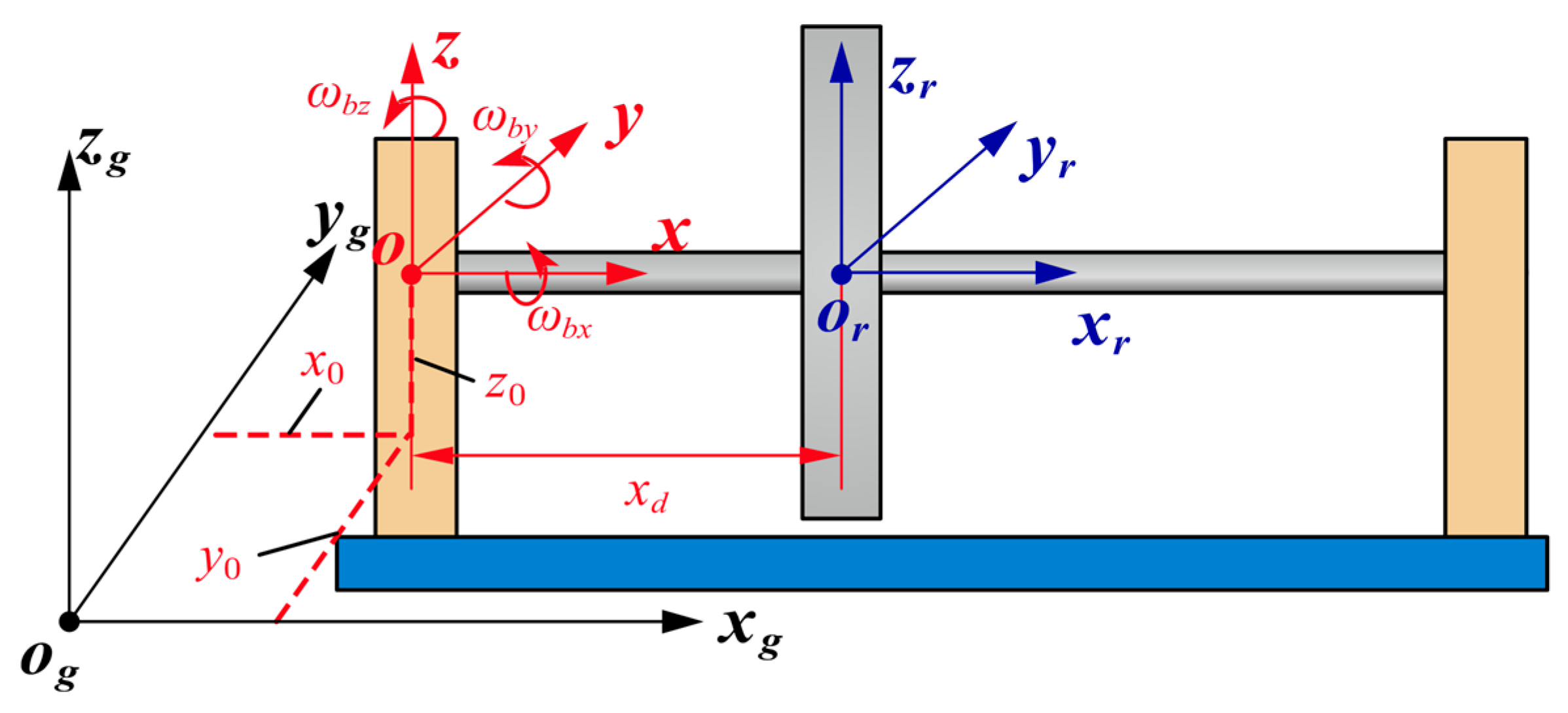
Figure 1. Coordinate systems for describing base motions.
Applsci 15 01186 g001
Figure 2. Diagram of the squeeze film damper.
Applsci 15 01186 g002
Figure 3. Diagram of the predictor–corrector method.
Applsci 15 01186 g003
Figure 4. Diagram of the arc-length continuation-based HB-AFT method.
Applsci 15 01186 g004
Figure 5. Three types of Floquet multipliers leaving the unit circle.
Applsci 15 01186 g005
Figure 6. Stability chart calculated from: (a) Han and Chu [35]; (b) the proposed model.
Applsci 15 01186 g006
Figure 7. Dimensionless amplitude–frequency response curve at nodal point of: (a) SFD (Han et al. [27]); (b) disk (Han et al. [27]); (c) SFD (the proposed model); (d) disk (the proposed model).
Applsci 15 01186 g007
Figure 8. Diagram of a rotor-SFD system with an offset disk.
Applsci 15 01186 g008
Figure 9. Frequency–response curves of harmonic components under fixed base conditions ( C / R = 0.485 % ,   U = 360.04   g m m ) at nodal points of: (a) SFD; (b) disk.
Applsci 15 01186 g009
Figure 10. Amplitude–frequency characteristics at SFD node during base rolling motion ( C / R = 0.485 % ,   U = 144.02   g m m ): (a) complete response curves; (b) magnified view.
Applsci 15 01186 g010
Figure 11. Frequency–response curves of harmonic components under base rolling motion ( C / R = 0.485 % ,   U = 144.02   g m m ,   ω b x = 10   r a d / s ) at nodal points of: (a) SFD; (b) disk.
Applsci 15 01186 g011
Figure 12. Amplitude–frequency characteristics during base rolling motion ( C / R = 0.485 % ,   U = 144.02   g m m ) at nodal points of: (a) SFD; (b) disk.
Applsci 15 01186 g012
Figure 13. Frequency–response curves of harmonic components under base pitching motion ( C / R = 0.485 % ,   U = 144.02   g m m ,   ω b y = 6   r a d / s ) at nodal points of: (a) SFD; (b) disk.
Applsci 15 01186 g013
Figure 14. Rotor trajectories at the SFD node under different rotational speeds ( C / R = 0.485 % ,   U = 144.02   g m m ,   ω b y = 6   r a d / s ).
Applsci 15 01186 g014
Figure 15. Frequency–response curves of harmonic components at disk node under base pitching motion ( C / R = 0.485 % ,   U = 144.02   g m m ): (a) ω b y = 8   r a d / s ; (b) ω b y = 9   r a d / s ; (c) ω b y = 10   r a d / s .
Applsci 15 01186 g015
Figure 16. Frequency–response curves and rotor trajectories at the SFD node under base yawing motion ( C / R = 0.485 % ,   U = 144.02   g m m ) (a) frequency–response curves; (b) rotor trajectories (red: clearance; dot: center).
Applsci 15 01186 g016
Figure 17. Frequency–response curves and rotor trajectories at the SFD node under base pitching motion ( C / R = 0.485 % ) (a) U = 252   g m m ; (b) U = 360.04   g m m .
Applsci 15 01186 g017
Figure 18. Frequency–response curves and rotor trajectories at the disk node under base pitching motion ( C / R = 0.485 % ) (a) U = 252   g m m ; (b) U = 360.04   g m m .
Applsci 15 01186 g018
Figure 19. The unstable rotational speed range varies with respect to pitching angular velocity ( C / R = 0.485 % ).
Applsci 15 01186 g019
Figure 20. Frequency–response curves of harmonic components at SFD node under base pitching motion ( C / R = 0.485 % ,   ω b y = 9   r a d / s ): (a) U = 252   g m m ; (b) U = 360.04   g m m .
Applsci 15 01186 g020
Figure 21. Frequency–response curves at the SFD node under base pitching motion ( U = 252   g m m ,   ω b y = 10   r a d / s ) (a) horizontal displacement; (b) vertical displacement.
Applsci 15 01186 g021
Figure 22. Frequency–response curves at SFD nodes under base pitching motion ( C / R = 0.728 % ,   U = 252   g m m ,   ω b y = 10   r a d / s ): (a) horizontal displacement; (b) vertical displacement.
Applsci 15 01186 g022
Figure 23. Rotor trajectories, phase diagrams, and Poincaré sections ( C / R = 0.728 % ,   U = 252   g m m ,   ω b y = 10   r a d / s ) at various rotational speeds: (a) Ω ~ = 1.025 ; (b) Ω ~ = 1.05 ; (c) Ω ~ = 1.075 ; (d) Ω ~ = 1.10 .
Applsci 15 01186 g023aApplsci 15 01186 g023b
Figure 24. Frequency–response curves at the SFD node under base pitching motion ( C / R = 0.728 % ,   ω b y = 10   r a d / s ) (a) horizontal displacement; (b) vertical displacement.
Applsci 15 01186 g024
Table 1. Maximum Floquet multipliers at the bifurcation points.
Mass Unbalance
g m m
Literature [27]The Proposed Model
Ω ~ u m a x Ω ~ u m a x
144.021.06411.00141.05651.0048
1.05781.00981.05561.0351
360.041.31241.07551.28201.0047
1.12811.05141.12451.0189
Table 2. Primary parameters of SFD.
Oil Viscosity
μ p a s
Oil Clearance
C m m
Clearance-to-Radius Ratio
C / R
Length-to-Diameter Ratio
L s f d / D
0.005112.70.485%0.325
Table 3. Floquet multiplier variations at bifurcation points.
Bifurcation Point Ω ~ Floquet   Multiplier   u m a x
A1.03691.0589
B1.09820.5344 ± 0.8634 i
C1.29771.0008
D1.16601.0716
E1.17601.0669
F1.16691.0818
Disclaimer/Publisher’s Note: The statements, opinions and data contained in all publications are solely those of the individual author(s) and contributor(s) and not of MDPI and/or the editor(s). MDPI and/or the editor(s) disclaim responsibility for any injury to people or property resulting from any ideas, methods, instructions or products referred to in the content.