Article

Energy Consumption Analysis of 2Z-X(B) Planetary Input-Coupled Hydro-Mechanical Tractor Transmission

1
College of Mechanical and Electronic Engineering, Shandong Agricultural University, Taian 271018, China
2
Shandong Weifang Luzhong Tractor Co., Ltd., Weifang 261057, China
3
College of Engineering, Ocean University of China, Qingdao 266404, China
4
National Engineering Research Center of Agricultural Production Machinery and Equipment, Taian 271018, China
*
Author to whom correspondence should be addressed.
These authors contributed equally to this work.
Appl. Sci. 2025, 15(23), 12576; https://doi.org/10.3390/app152312576
Submission received: 26 October 2025 / Revised: 23 November 2025 / Accepted: 24 November 2025 / Published: 27 November 2025
(This article belongs to the Special Issue State-of-the-Art Agricultural Science and Technology in China)

Abstract

The hydro-mechanical transmission (HMT) of continuously variable transmission tractors typically achieves speed regulation using a 2Z-X(A) planetary gear system. Long-term use of this setup has created a strong patent barrier, hindering further HMT structural innovation. This study systematically examines the energy consumption characteristics of HMTs based on a 2Z-X(B) planetary gear set configuration, aiming to provide a theoretical reference for developing new HMT tractors. First, the powertrains of both 4-range and 2-range HMTs using this configuration are described. Next, a mathematical model of the 4-range HMT is developed, and its hydrostatic power portion, transmission efficiency, and fuel consumption are analyzed. Finally, the energy consumption characteristics of the 2-range HMT are compared with those of the 4-range HMT, highlighting their performance differences. Results indicate that HMTs based on the 2Z-X(B) planetary gear set exhibit similar efficiency characteristics to traditional systems, with a maximum efficiency exceeding 90%. The impact of efficiency on HMT fuel economy is greater than that of engine fuel consumption itself, suggesting that an efficiency-prioritized power matching control strategy is feasible.

1. Introduction

To improve agricultural production efficiency, agricultural machinery such as tractors is developing towards larger sizes [1]. Due to a wide range of working conditions, high-power tractors have complex transmission structures, with a much greater number of gears than road vehicles [2]. For instance, tractor manufacturers like YTO, Weichai Levo, and Deutz-Fahr have successively developed high-power tractors featuring over 80 gears. To simplify the transmission structure and enhance driving comfort, hydraulic mechanical transmissions (HMTs), which enable high-efficiency stepless variable speed, have emerged as an ideal transmission system for high-power tractors [3,4]. The fundamental principle of the transmission system involves dividing engine power into two streams upon entering the transmission. One stream feeds into the hydraulic circuit, utilizing swash plate axial piston units with an adjustable transmission ratio, while the other enters the mechanical circuit via gear transmission. These two power paths converge at the planetary gear set and exit rearward. By routing only a portion of power through the less efficient hydraulic system, this setup retains the high efficiency of mechanical transmission alongside the substantial load-driving capability of hydraulic transmission. While hybrid mechanical–hydraulic transmissions integrate these dual advantages, their theoretical transmission efficiency remains lower than that of pure mechanical systems. This limitation, however, does not hinder HMTs from serving as a low-fuel-consumption transmission solution for tractors. The fuel consumption of HMT-equipped tractors is influenced by both powertrain efficiency and power-matching strategies. The same operating speed can be achieved through various combinations of engine speeds and transmission ratios, each corresponding to distinct fuel consumption levels. HMTs function as transmissions with theoretically infinite gears, offering superior power matching capabilities compared to traditional transmissions. This allows HMTs to achieve high fuel efficiency despite their relatively lower transmission efficiency. Existing research supports this assertion: İnce and Güler [5] compared fuel consumption between HMTs and mechanical-shift transmissions, while Macor and Rossetti [6] conducted a similar comparison between HMTs and power-shift transmissions; both studies confirmed that HMTs exhibit lower fuel consumption than conventional transmissions. However, the extent of fuel efficiency improvements attributed to HMTs varies significantly across studies, ranging from 5% to 30% [7,8,9]. Since the power matching strategies employed in these studies have been fully optimized, the significant discrepancy observed may stem from the diversity of HMT configurations.
Theoretically, there are over 1000 configurations of HMTs [10], yet they can be categorized into two primary types: planetary output-coupled HMTs and planetary input-coupled HMTs. The former employs a planetary gear set for power splitting, while the latter utilizes it for power convergence. The Fendt Vario transmission, featured in the world’s first infinitely variable transmission tractor, exemplifies a planetary output-coupled HMT [11]. This transmission boasts a simplified structure, enabling full-process stepless speed regulation with a single speed range. However, its hydrostatic power portion is excessively large, making it challenging to achieve high-performance hydraulic units. Consequently, only a few manufacturers, such as Fendt, currently adopt this transmission type, leading the mainstream tractor HMT scheme to favor the planetary input-coupled configuration. The structural design of planetary gear sets is also critical; based on the Kyдpявцeв method [12], they can be broadly classified into three fundamental configurations: 2Z-X, 3Z, and Z-X-V. Among these options, 3Z and Z-X-V planetary gear sets, characterized by complex structures or low efficiency, are rarely employed as tractor power transmission mechanisms. In the 2Z-X series planetary gear set (Figure 1), Types A and B exhibit the highest transmission efficiency, ranging from 97% to 99%. Type C is typically employed in vehicle differentials, while Type D is seldom utilized for high-power transmission due to its low efficiency. Types E1 and E2 feature complex structures and significantly lower transmission efficiency compared to Types A and B. Consequently, only the Type A, Type B and their cascade configurations are suitable for tractor transmission. It is important to note that despite its simple structure, Type A is rarely employed independently in HMTs. If used alone, HMT would require clutch switching during shifts, along with rapid adjustment of the pump or motor displacement to eliminate pre- and post-shift speed differences. For this reason, Type A typically necessitates multiple cascaded components (e.g., Simpson planetary gear sets) for practical applications. In contrast, Type B achieves multi-range output by incorporating additional sun gears, which inherently provide speed synchronization points and thus simplify the shifting process. From this standpoint, Type B demonstrates acceptable structural complexity.
Currently, Type A and its derivative configurations within the 2Z-X series planetary gear sets have gained widespread adoption owing to their superior performance. Numerous studies have focused on tractor HMTs featuring 2Z-X(A) planetary input-coupled configurations. Notable contributions include research by Li et al. [13] and Xia et al. [14] on HMT energy consumption, as well as investigations by Chen et al. [15] and Liu et al. [16] into HMT shifting dynamics. Among all research endeavors, a significant achievement is the elucidation of the relationship between HMT configuration and energy consumption, which is critical for tractor power matching control. In this area, Rosetti et al. [17,18] performed parameter optimization across all possible configurations of a single 2Z-X(A) planetary gear set and analyzed their respective energy consumption profiles. Calculating energy consumption of HMT is essential in these studies. The predominant approach involves treating the power split system as a closed transmission chain. This method proceeds by first determining the direction of power flow using the symbolic method, followed by calculating the hydraulic system efficiency, and ultimately computing the total efficiency of the closed planetary gear transmission via the meshing power method [19]. Alternative approaches to the meshing power method include the Kpeйнec method [12], and relative power method [20], among others. Efficiency values obtained through this method for HMT under full load differ markedly from published experimental results, primarily because hydraulic system efficiency is calculated independently, thereby severing the coupling between mechanical and hydraulic energy consumption. To address this issue, Zhang et al. [21] established a coupling relationship between the mechanical and hydraulic subsystems by solving the hydraulic system’s flow continuity equation under specific operating conditions alongside the torque balance equation of the HMT input shaft, which enhanced the accuracy of HMT efficiency calculations. However, this method is complex and not applicable to all operating conditions. One of the present authors, Wang [22], developed a hydraulic transmission model grounded in energy and flow conservation principles, integrating it into the mechanical system for iterative computation. This approach enables the determination of HMT efficiency across any operating condition. Additionally, simplified HMT models exist for qualitative analysis of control strategies [23,24], alongside general models applicable to all power-split systems [25,26]. However, these models have not been experimentally validated and will not be detailed herein. It is important to note that the aforementioned methods were specifically designed for efficiency calculations of 2Z-X(A) type HMT.
After nearly three decades of industrialization, the 2Z-X(A) input-coupled configuration has been widely adopted, making it increasingly challenging to propose new innovative HMT configurations. Consequently, the 2Z-X(B) input-coupled configuration has emerged as the most promising candidate for developing next-generation tractor HMTs. Currently, research on this HMT variant remains scarce, with no existing work systematically investigating its transmission efficiency or fuel efficiency. This lack of understanding hinders the development of its transmission system and the formulation of effective control strategies. Consequently, this study examines the transmission performance of Case New Holland’s (CNH) 4-range tractor HMT, a typical example of the 2Z-X(B) input-coupled design and compares it with CNH’s 2-range counterparts. The objective is to explore the energy consumption characteristics of this novel HMT, thereby facilitating its industrial application.

2. Materials and Methods

2.1. Powertrain

This study investigates the impact of the number of ranges on the HMT energy consumption of the Case New Holland tractor [27]. It first analyzes the transmission efficiency and fuel efficiency of the 4-range HMT, followed by a comparison of its transmission performance with that of the 2-range HMT.
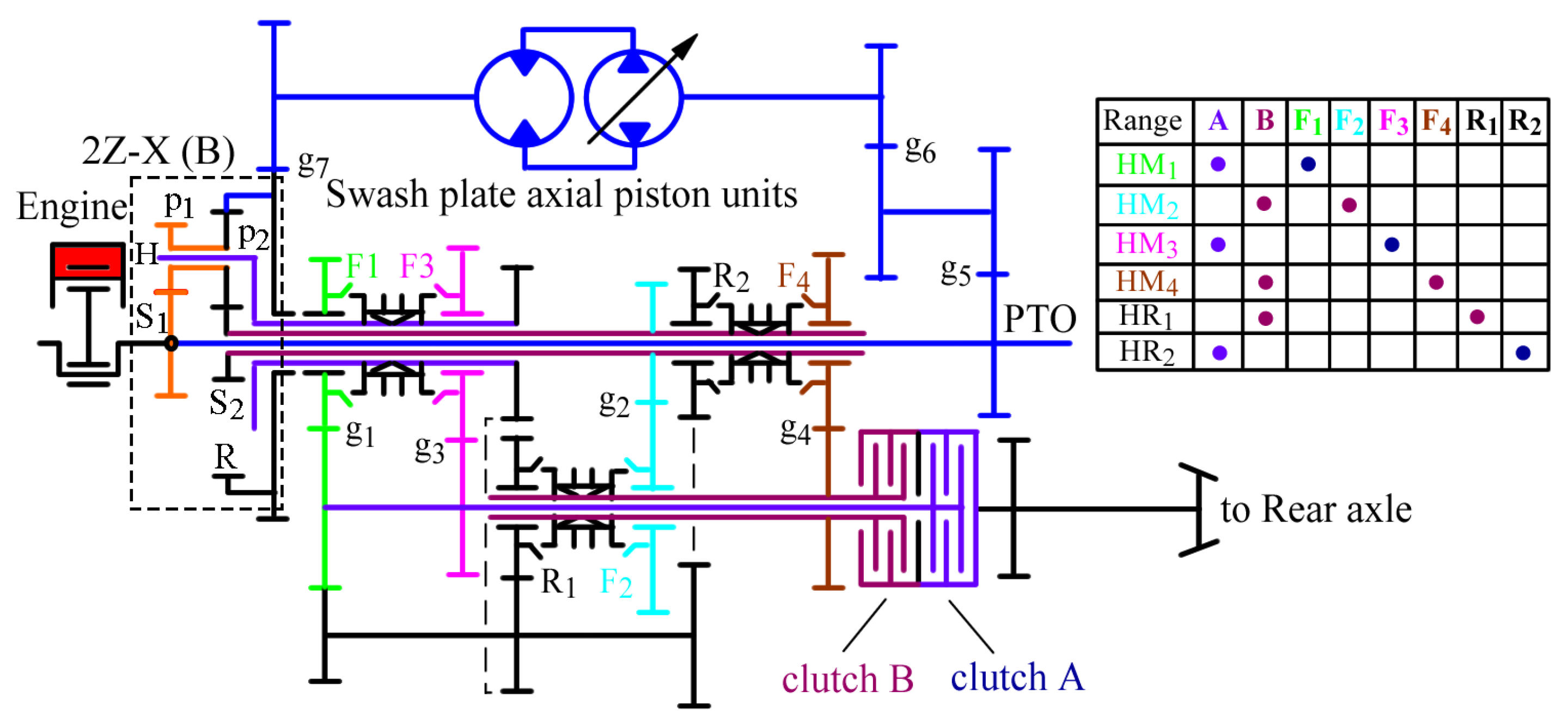
Case New Holland’s 4-range HMT tractor features a 2Z-X(B) planetary input-coupled configuration, incorporating a compact ‘back-to-back’ variable piston pump and fixed-displacement hydraulic motor, along with three synchronizers and a two-way wet clutch. The transmission layout and clutch scheduling are illustrated in Figure 2. As shown, engine power splits into two paths: one to the pump shaft within the hydraulic unit and another to the S1 shaft of the mechanical system. Power from the hydraulic system is delivered via the motor shaft and combines with mechanical system power at the planetary gear set. For ranges HM1/HM3 and HM2/HM4, power exits through the planet carrier H and sun gear S2, respectively, before being transferred to the rear axle via wet clutches A or B.
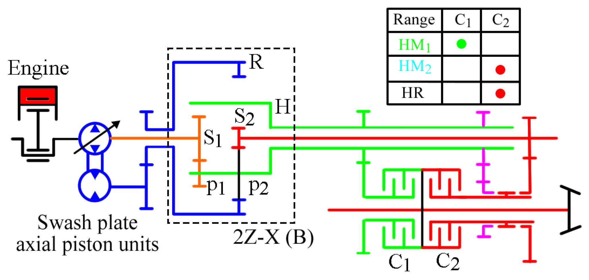
Case New Holland’s 2-range HMT is illustrated in Figure 3. Its power-split principle mirrors that of the 4-range version and thus will not be reiterated here. To facilitate comparison, the engines and swash plate axial piston units of both the 4-range and 2-range HMTs have been reselected to ensure they operate at the same power level, namely 132.5 kW.

2.2. Modeling

2.2.1. Swash Plate Axial Piston Units

In closed hydraulic system, the function of variable pump is to convert mechanical energy into hydraulic energy. When the pump shaft speed and the pressure difference between the inlet and outlet oil lines are known, the torque of the pump shaft is:
T p = ε V p m a x d p / η h m 1
where T p is the pump shaft torque, N∙m; ε is the ratio of pump displacement to its rated value; V p m a x is the rated displacement of the pump, cm3/rev; d p is the pressure difference between the outlet and inlet of the pump, which is numerically equal to the pressure difference between the inlet and outlet of the motor, bar; η h m 1 is the mechanical efficiency of the pump, %.
The output flow of the pump is the same as the input flow of the motor, and the values are:
Q p m = ε V p m a x n p η v o l 1
where Q p m is the flow of the closed system, L/min; n p is the pump shaft speed, r/min; η v o l 1 is the volumetric efficiency of the pump, %.
The role of the motor is to convert hydraulic energy into mechanical energy. When the torque of the motor shaft and the flow of the closed system are known, the speed of the motor shaft is:
n m = Q p m η v o l 2 / V m
where n m is the motor shaft speed, r/min; η v o l 2 is the volume efficiency of the motor, %; V m is the displacement of the motor, cm3/rev.
The pressure difference of the closed system is:
d p = T m / η h m 2 V m
where T m is the torque of motor shaft, N∙m; η h m 2 is the mechanical efficiency of the motor, %.
By combining Equations (2) and (3), we derive:
n m = ε V p m a x n p η v o l 1 η v o l 2 / V m
When volumetric efficiency is not considered, the rotating speed of the motor shaft is:
n m = n p ε V p m a x / V m = n p e
where e = ε V p m a x / V m is the displacement ratio of the pump to motor.
In the above equations, the mechanical efficiency and volumetric efficiency of pump and motor are functions of rotating speed, pressure difference and displacement:
η h m 1 = f n p , d p , ε V p m a x η h m 2 = f n m , d p , V m η v o l 1 = f n p , d p , ε V p m a x η v o l 2 = f n m , d p , V m
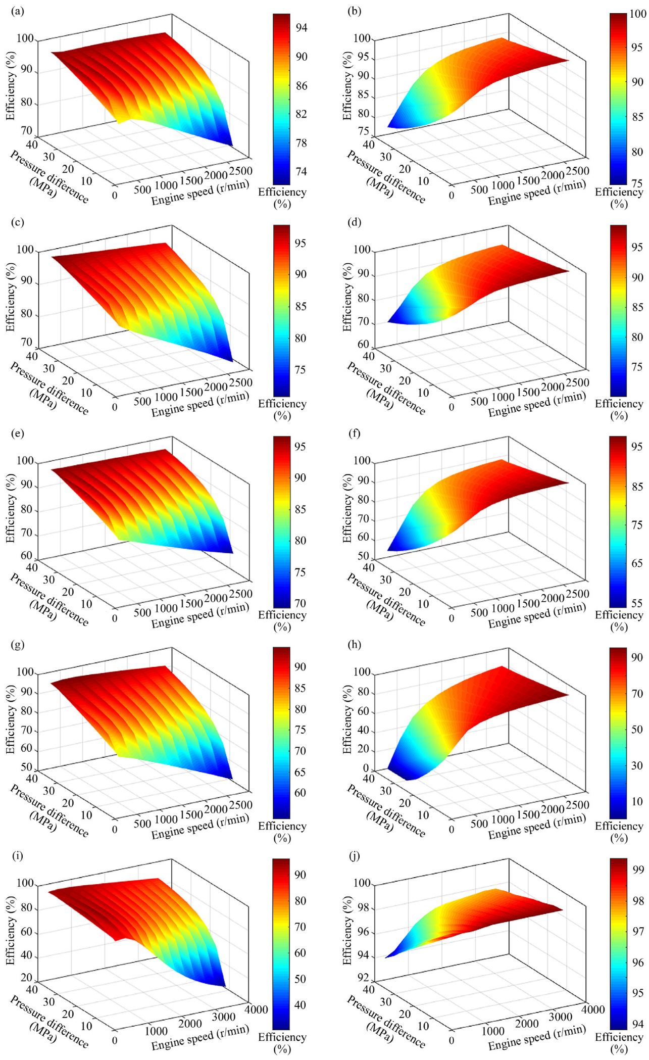
To improve the reliability of the study, the efficiency of the hydraulic units in Equation (7) is measured and provided by their manufacturers, as shown in Figure 4.

2.2.2. Gear Pairs and Planetary Gear Sets

For a standard gear pair, the rotational speed of the driven gear and the torque of the driving gear are defined as follows:
n C   =   n Z / i
T Z = T C / i η l o s t
where n Z and n C are the rotating speeds of the driving gear and driven gear, respectively, r/min; i is the transmission ratio of the gear pair; T Z and T C are the torque of the driving gear and driven gear, respectively, N∙m; η l o s t is the meshing efficiency of the gear pair, %.
The 2Z-X(B) planetary gear set can be decomposed into two standard 2Z-X(A) planetary gear sets, designated PG1 and PG2, which share a common ring gear and planet carrier. For a standard planetary gear set, the rotational speed of each basic component satisfies:
n S + k n R 1 + k n H   =   0
where n S , n R and n H are the rotation speeds of the sun gear, ring gear and planet carrier, respectively, r/min; k is the standing ratio of the planetary gear set.
For planetary gear set PG1 and PG2, their standing ratios are:
  k   = Z R Z p 1 / Z p 2 Z S 1   PG 1 Z R / Z S 2 PG 2
where Z R , Z S 1 and Z S 2 are the number of teeth of the ring gear, sun gear S1 and sun gear S2, respectively; Z p 1 and Z p 2 are the number of teeth of the planetary gears p1 and p2, respectively.
The torque calculation for a planetary gear set must be performed within its conversion mechanism and adhere to the following relationships:
T S + T R + T H = 0
where T S , T R and T H are the torques of the sun gear, ring gear and planet carrier, respectively, N∙m.
When the power flows from the sun gear to the ring gear:
T S n S H + T R n R H / η s r 1 η s r 2   =   0
where n S H and n R H are the rotational speeds of the sun gear and ring gear relative to the planetary carrier, respectively, r/min; η s r 1 is the meshing efficiency between the sun gear and planetary gear, %; η s r 2 is the meshing efficiency between the planetary gear and ring gear, %.
On the contrary, when the power flows from the ring gear to the sun gear:
T S n S H / η s r 1 η s r 2 + T R n R H   =   0
The torque of each basic component of the planetary gear set can be obtained through simultaneous Equations (12)–(14), which will not be repeated here.

2.2.3. Energy Consumption Calculation

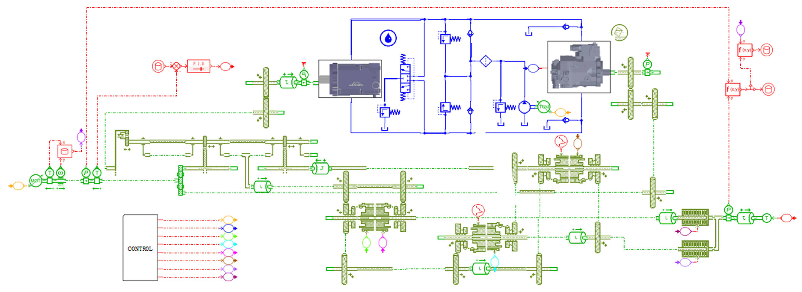
The energy consumption calculation model for the Case New Holland 4-range tractor HMT has been developed within AMESim (Version 2020.1), as illustrated in Figure 5. Each library component in AMESim provides multiple selectable mathematical models. The necessary mathematical models were selected based on the previously mentioned equations, or custom mathematical models were encapsulated where required.
The transmission energy consumption is determined using the following equation:
η t = ( n t T t ) / ( n e T e )
where η t is the transmission efficiency of the HMT, %; n e and n t are the input speed and output speed of the HMT, respectively, r/min; T e and T t are the input torque and output torque of the HMT, respectively, N·m.
The fuel economy of the transmission is represented by the system fuel consumption:
g t = g e / η t
where g e is the engine’s fuel consumption, g/(kw·h); g t is the fuel consumption of the “Engine-HMT” system, i.e., the engine’s fuel consumption per unit of work output by the transmission, g/(kw·h).

2.2.4. Model Limitations

When applying the aforementioned model, the following limitations should be noted:
(1)
Case New Holland’s 4-range and 2-range HMTs are designed to address distinct market demands. To facilitate a fair comparison between two different power-level transmission systems and to elucidate the relationship between HMT configuration and energy consumption, we have reselected the engine (WP6T180E21, Weichai Power Co., Ltd., Weifang, China), pump (A4VG32, Bosch Rexroth, Shanghai, China), and motor (A6VM63, Bosch Rexroth, Shanghai, China) for the HMTs. This adjustment results in the two drivetrains under study being theoretical constructs; thus, the calculated outcomes cannot be directly equated to actual product performance.
(2)
The model presented in this study is an adaptation of an energy consumption calculation model for Simpson HMT, originally developed by our research group in an earlier phase and experimentally validated across multiple operating conditions [22]. Given that both Simpson and 2Z-X(B) planetary gear sets can be decomposed or equivalent to two standard 2Z-X(A) planetary gear sets, their technical routes are consistent. Unlike the original model, this study replaces the hydraulic system simulation sub model based on energy and flow conservation in the original model with the hydraulic system efficiency map obtained from manufacturer experiments, thereby limiting the source of calculation errors to the high-efficiency mechanical transmission part. This treatment is theoretically more reliable because mechanical transmission, mainly gear transmission, has high efficiency, and its calculation error within a certain range has a very limited impact on the overall calculation results.
(3)
A limitation of this model is that the meshing efficiency of the gear pair has not been calibrated and is treated as a constant (e.g., 0.98), a common practice in engineering calculations. This approach suffices for the theoretical analysis and comparative work conducted herein, as the primary objective is to identify patterns rather than obtain precise numerical values. However, if the model is to be used for precise evaluation of specific product performance, it will be necessary to calibrate the transmission parameters via bench testing, and where required, employ optimization algorithms to adjust these parameters.

3. Results

3.1. Speed Characteristics

The transmission ratio is continuously adjustable, with its value determined by the HMT range and the displacement ratio of the pump to motor. The specific equation is as follows:
i H M 1   =   1 + k 1 i 5 i 6 i 7 i 1 / i 5 i 6 i 7 + k 1 e
i H M 2 = 1 + k 1 i 5 i 6 i 7 i 2 / k 1 k 2 e + 1 + k 2 i 5 i 6 i 7
i H M 3   = 1 + k 1 i 5 i 6 i 7 i 3 / i 5 i 6 i 7 + k 1 e
i H M 4 = 1 + k 1 i 5 i 6 i 7 i 4 / k 1 k 2 e + 1 + k 2 i 5 i 6 i 7
where i H M 1 i H M 4 are the transmission ratios of the HMT in ranges HM1–HM4, respectively; i 1 i 7 are the transmission ratios of the gear pairs g1–g7 in Figure 2, respectively.
The tractor’s driving speed is calculated as follows:
v t   =   0.377 n e R d / i H M x i R a x   =   1 , , 4
where v t is the speed of the tractor, km/h; R d is the power radius of the tractor’s driving wheel, m; i R a is the transmission ratio of the tractor’s rear axle.
Based on the aforementioned equations, the speed regulation characteristics of the HMT were simulated, as illustrated in Figure 6. It should be noted that the transmission ratio at tractor startup is infinite. For ease of illustration, the vertical axis in Figure 6a depicts the reciprocal of the transmission ratio. As evident from the figure:
(1)
This HMT is capable of starting from zero speed with maximum displacement ( e = 1 ) in HM1 range. Consequently, it eliminates the need for an additional dedicated hydrostatic range for starting, which simplifies the overall transmission system structure.
(2)
The transmission ratio of the HMT is continuously adjustable, with the ratios of adjacent ranges seamlessly interconnected. This allows the HMT to achieve speed synchronization prior to range shifting, thereby significantly enhancing the shifting smoothness of the tractor.
(3)
The absolute value of the displacement ratio of the pump to motor at the theoretical shift point is less than 1, enabling the HMT to achieve speed synchronization even when the swash plate axial piston units experience speed loss.
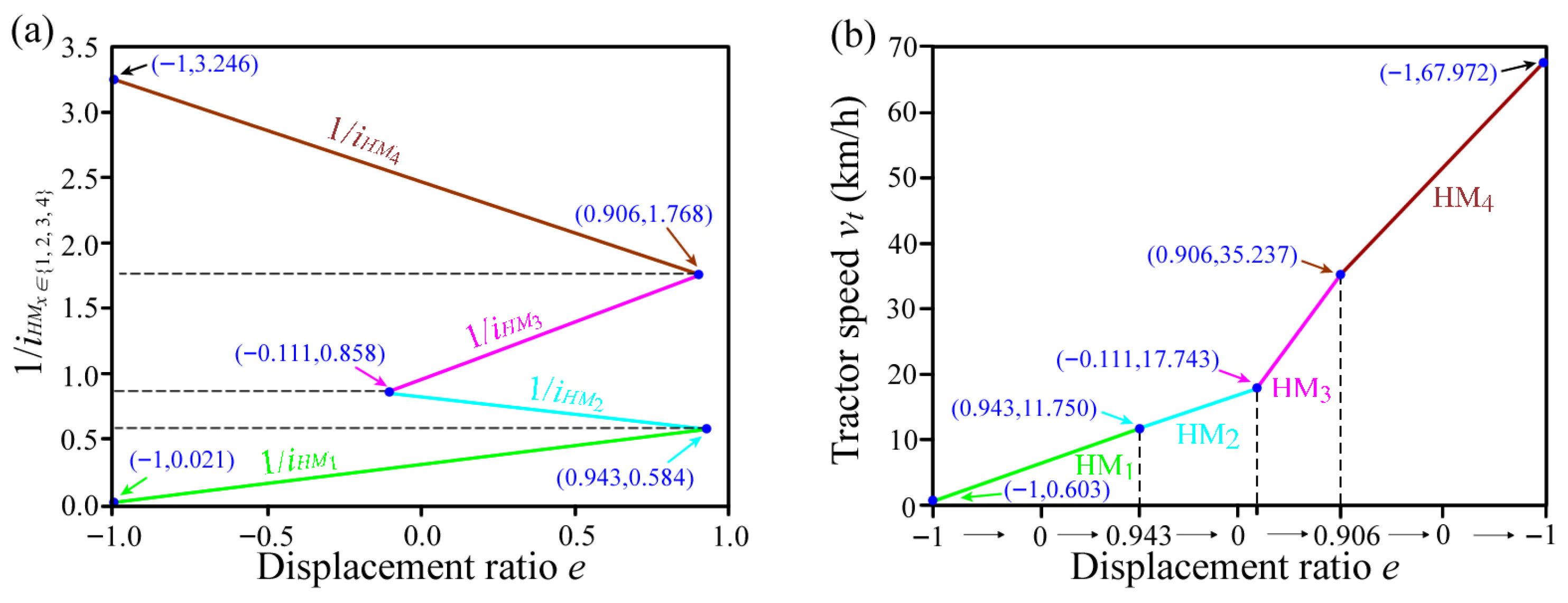
Figure 6. Speed characteristics of HMT: (a) Reciprocal of transmission ratio; (b) Tractor speed.
Applsci 15 12576 g006

3.2. Power Characteristics

The rotational speed and torque of each shaft within the planetary gear set are recorded via simulation, with the sign of the value indicating the direction. When the shaft’s rotational speed aligns with the direction of the applied torque, this is designated as the driving end; conversely, when they oppose each other, it is classified as the load end. The power can only flow from the driving end to the load end, so the flow direction of the engine power in the HMT planetary gear set can be obtained, as shown in Figure 7. It can be seen from the figure:
(1)
For ranges HM1/HM3: when the displacement ratio of the pump to motor is negative, the mechanical power input from the sun gear S1 flows partly along the planet carrier to the output shaft, and the other part flows back to the hydraulic motor along the ring gear to form parasitic power; when the displacement ratio of the pump to motor is positive, the mechanical power input from the sun gear S1 and the hydraulic power input from the ring gear flow to the output shaft through the planet carrier together after the confluence, and there is no parasitic power.
(2)
For ranges HM2/HM4: when the displacement ratio of the pump to motor is positive, part of the mechanical power input from the sun gear S1 flows along the sun gear S2 to the output shaft, and the other part flows back to the hydraulic motor along the ring gear to form parasitic power; when the displacement ratio of the pump to motor is negative, the mechanical power input from the sun gear S1 and the hydraulic power input from the ring gear flow together to the output shaft through the sun gear S2 after the confluence, and there is no parasitic power.
(3)
The direction of change in the displacement ratio depicted in the figure corresponds to the acceleration direction of the HMT. It is evident that parasitic power occurs on the side with lower output speed within each operating range. This parasitic power does not contribute to external work and results in internal energy loss, significantly impacting the transmission efficiency of the HMT.
Figure 7. Power flow direction of HMT.
Applsci 15 12576 g007
Since the efficiency of hydraulic transmission is significantly lower than that of mechanical transmission, the hydrostatic power portion determines the actual efficiency level of HMT regardless of the presence or absence of parasitic power.
For ranges HM1/HM3:
ρ = P R / P S 1 e < 0 P R / P H e > 0
where ρ is the hydrostatic power portion, %; P S 1 , P R and P H are the power of the sun gear S1, ring gear and planet carrier, respectively, kW.
For ranges HM2/HM4:
ρ = P R / P S 2 e < 0 P R / P S 1 e > 0
where P S 2 is the power of the sun gear S1, kW.
The calculation results for the hydrostatic power portion of the tractor HMT at an input speed of 2200 r/min are presented in Figure 8. As illustrated in the figure:
(1)
The HMT features a near-100% hydrostatic power portion during startup. Post-startup, the HMT restricts the hydrostatic power portion to less than 34% via strategic range shifting. This approach prevents efficiency degradation by mitigating excessive energy consumption within the hydraulic system.
(2)
With the zero displacement point serving as the dividing line, the hydrostatic power portion on the high-speed side of each range is smaller than that on the low-speed side, a phenomenon clearly associated with parasitic power.
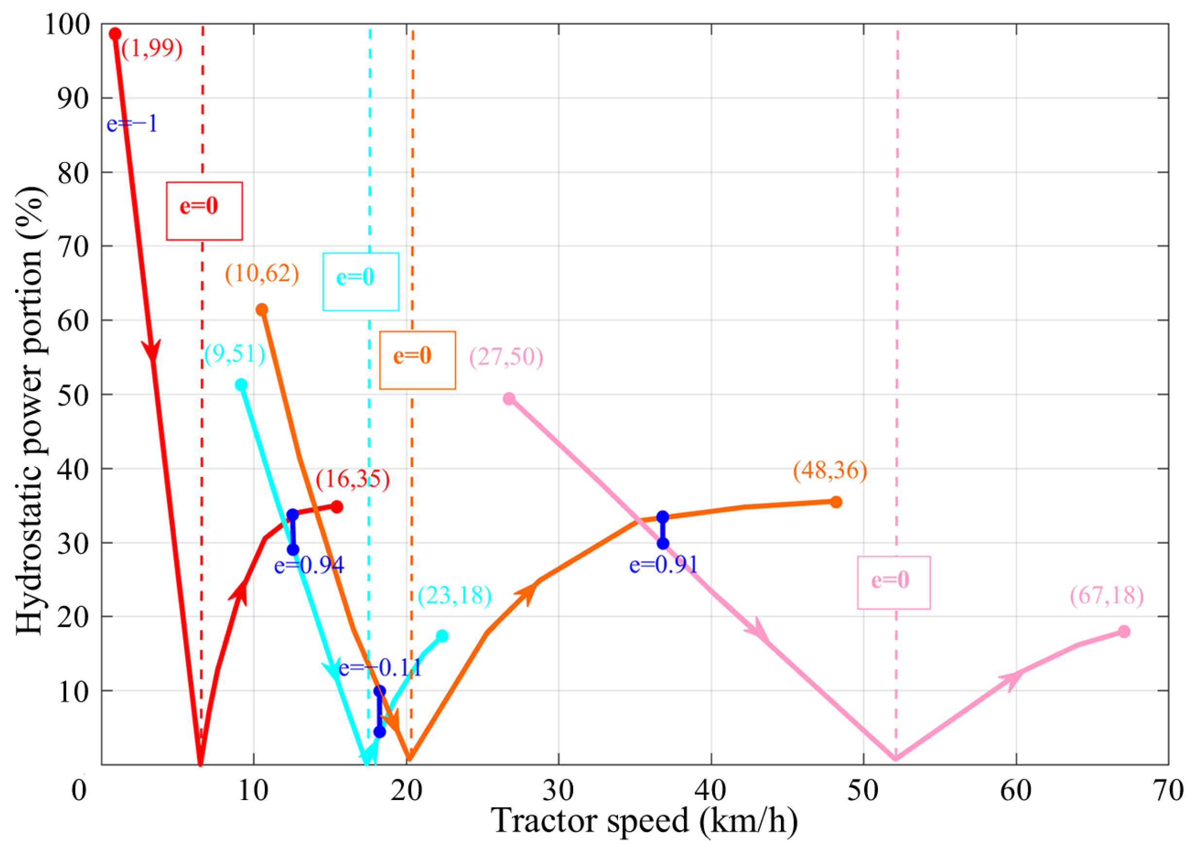
Figure 8. Simulation results of hydrostatic power portion.
Applsci 15 12576 g008

3.3. Efficiency Characteristics

3.3.1. Full Load Efficiency

To calculate the full load efficiency of HMT, the process begins by specifying the input speed, pump displacement, and clutch state. Subsequently, the load is incrementally increased from 0 N·m up to the maximum torque constrained by the engine’s external characteristics. A PID module is integrated into the simulation model to automatically correct the deviation between the target torque and the actual torque, ensuring rapid convergence of the calculation model. Simulations were conducted at three distinct input speeds: 2200, 1500, and 1000 r/min, with corresponding maximum torques of 584, 752, and 665 N·m, respectively. These three operating points correspond to the engine’s maximum power point, maximum torque point, and minimum stable operating point, respectively. The calculation results are presented in Figure 9. As shown in the figure:
(1)
The maximum full-load efficiency of the HMT is around 95%, which is comparable to the efficiency of the HM8 transmission disclosed by Claas. For any range, the HMT only uses the speed range under its partial pump displacement.
(2)
Viscous damping influences cause the full-load efficiency of the HMT to decrease as engine speed increases. Specifically, when engine speed rises from 1000 r/min to 2200 r/min, the maximum transmission efficiency of the HMT drops from 95% to 93%.
(3)
At low engine speeds, the high-speed side of each range exhibits higher efficiency than the low-speed side, primarily due to parasitic power losses. As engine speed increases, however, the high-speed side of each range experiences greater viscous damping losses compared to the low-speed side, causing these efficiency differences to diminish or become insignificant.
(4)
Under the condition of meeting the load power requirements, the HMT achieves the necessary operating speed by adjusting different engine speeds, thereby ensuring the HMT consistently operates at high transmission efficiency.
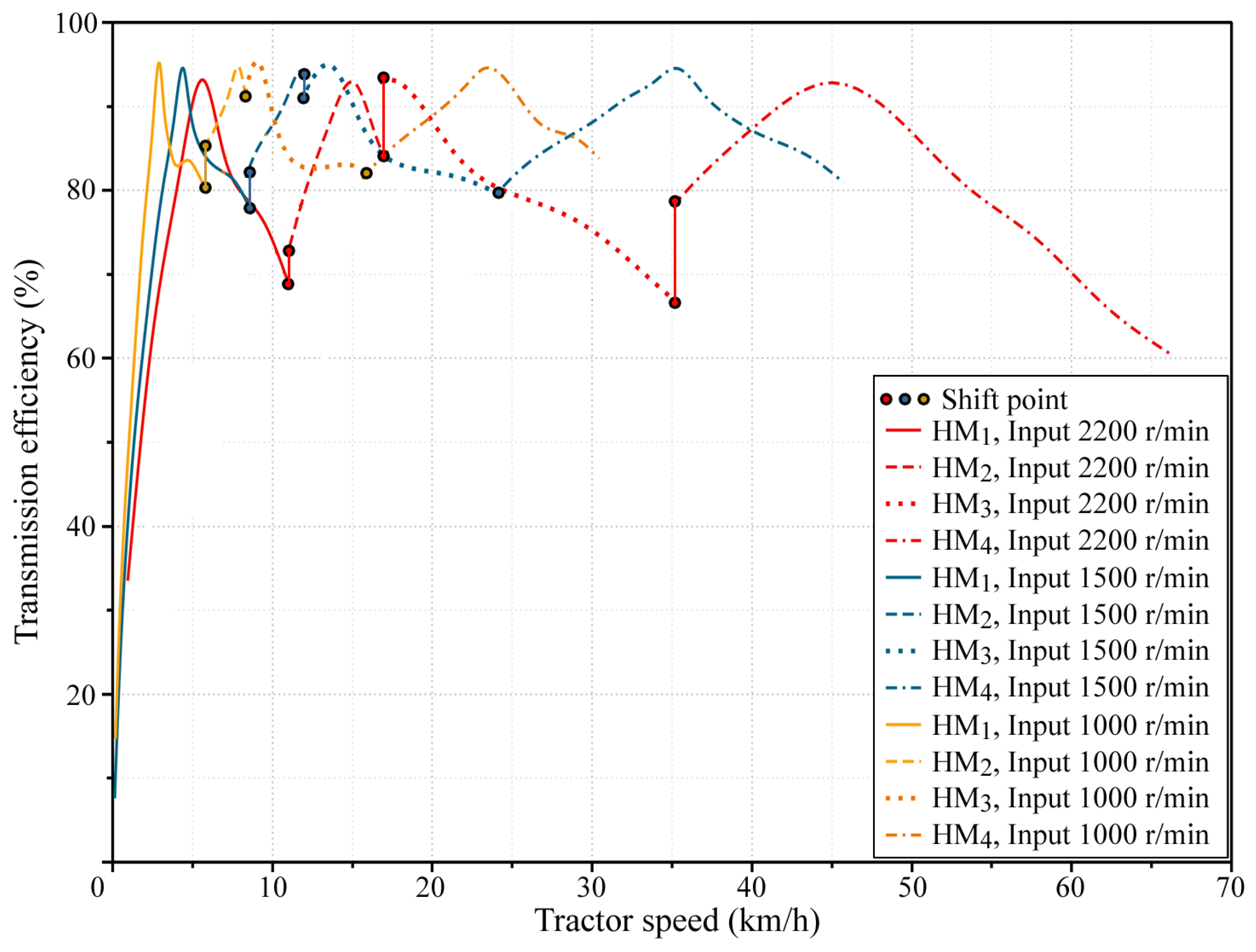
Figure 9. Full load efficiency of HMT.
Applsci 15 12576 g009

3.3.2. Partial Load Efficiency

The partial load efficiency of HMT at a specified tractor speed is computed using the following methodology: First, the target engine speed and torque are established, and the corresponding transmission ratio of the HMT at this target speed is determined. Subsequently, the necessary HMT range and pump displacement are calculated. Next, the load torque of the simulation model is incrementally adjusted via a PID module until the engine torque stabilizes at the target value. Finally, all operating points across the engine map are evaluated to derive the HMT efficiency at each point, which is then used to generate a contour map.
Given that the typical field operating speed range of tractors is 4–20 km/h, this study analyzes the efficiency characteristics of HMT within this speed range, as illustrated in Figure 10. The figure reveals:
(1)
Within each operating range, the absolute value of the pump-to-motor displacement ratio initially decreases and subsequently increases as engine speed rises. This behavior dictates a corresponding pattern for the hydrostatic power portion, resulting in a ‘U’-shaped distribution of the HMT’s efficiency contour. The mechanical point of the HMT (where e = 0) is situated at the midpoint of this ‘U’ shape, and the HMT exhibits high transmission efficiency within this region.
(2)
The efficiency contour exhibiting a ‘U’ shape is, in fact, a closed annular curve. This occurs because as load torque increases, the proportion of HMT’s basic energy consumption relative to total energy consumption decreases, thereby enhancing the transmission’s efficiency. However, when load torque becomes excessively high, the volumetric efficiency of both the pump and motor declines sharply, leading to speed loss and a reduction in overall transmission efficiency. Since the load torque necessary to close the ‘U’ curve exceeds the boundary of the engine’s external characteristic curve, this phenomenon is not observable in the diagram.
(3)
As tractor speed increases, the ‘U’ central area within the same range shifts toward higher engine speeds in response to changes in the displacement ratio. Theoretically, by maintaining the transmission at a consistently lower displacement ratio, an ‘engine-HMT’ control strategy optimized for maximum efficiency can be achieved.
(4)
As the HM2 and HM3 ranges shift at lower pump displacements, their high-efficiency regions converge, thereby expanding the engine’s speed range for high HMT efficiency and enhancing the flexibility of ‘engine-HMT’ power matching.
(5)
At a tractor speed of 6 km/h, the optimal efficiency region of the HMT is situated in the upper right corner of the engine map, overlapping with the engine’s high-power operating range. This indicates that the HMT can simultaneously satisfy both efficiency and power demands when engaged in heavy-duty operations such as ploughing at this speed.
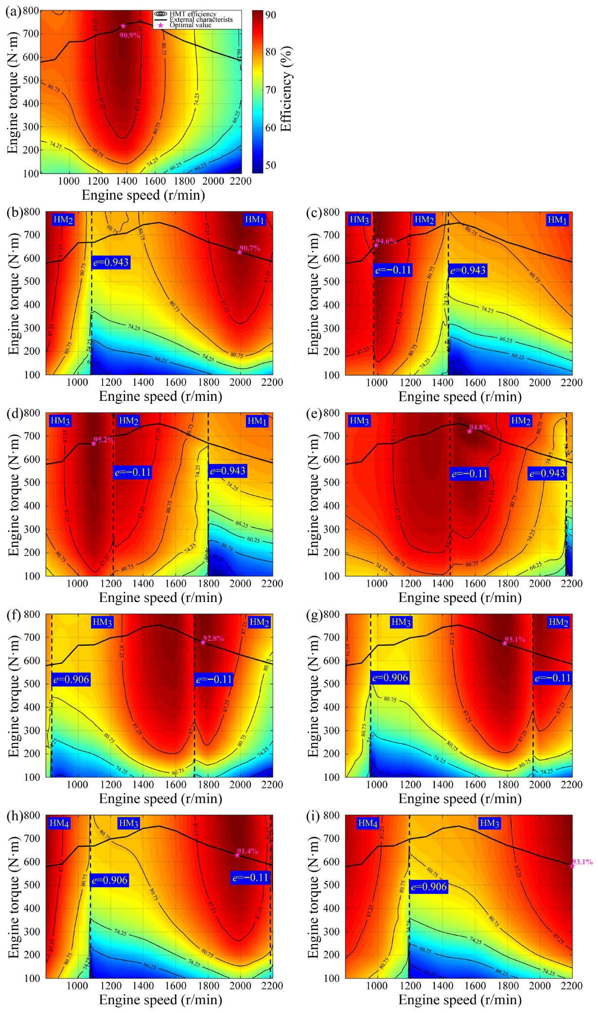
Figure 10. Energy consumption of HMT at various tractor speeds: (a) 4 km/h; (b) 6 km/h; (c) 8 km/h; (d) 10 km/h; (e) 12 km/h; (f) 14 km/h; (g) 16 km/h; (h) 18 km/h; (i) 20 km/h.
Applsci 15 12576 g010

3.4. Fuel Consumption Characteristics

Based on Equation (16), the fuel consumption map of the HMT at any tractor speed can be further derived, as illustrated in Figure 11. As evident from the figure:
(1)
At varying operating speeds, the fuel consumption of the tractor exhibits a comparable distribution and behavior pattern to the efficiency of the HMT. This indicates that the transmission efficiency of the HMT exerts a more significant influence on the tractor’s fuel efficiency than the engine itself.
(2)
A tractor speed of 6 km/h remains appropriate for heavy-load operations like ploughing. At this speed, the tractor effectively balances its power output with fuel efficiency.
(3)
The fuel consumption of the HMT tractor is notably higher under light load conditions, particularly when the engine’s load torque falls below 300 N·m. To mitigate this, it is recommended to operate in higher HMT ranges during light loads and to enhance engine torque by adjusting the HMT ratio downward.
Figure 11. Fuel consumption of “engine-HMT” system at various tractor speeds: (a) 4 km/h (b) 6 km/h (c) 8 km/h (d) 10 km/h (e) 12 km/h (f) 14 km/h (g) 16 km/h (h) 18 km/h (i) 20 km/h.
Applsci 15 12576 g011

4. Discussion

4.1. Comparison with Case New Holland 2-Range HMT

Using the same methodology, the full-load efficiency of the 2-range HMT was determined, as illustrated in Figure 12. As evident from the figure:
(1)
The efficiency of the HMT on the high-speed side of each range is significantly better than that on the low-speed side. Different from the 4-range HMT, this trend does not weaken with the increase of engine speed, which is very beneficial to the road transportation conditions of tractors.
(2)
Reducing the speed regulation range enhances tractor reliability by lowering shift frequency. However, fewer ranges increase the hydrostatic power portion of HMTs, reducing their efficiency at the low-speed side of each range. This results in a pronounced efficiency fluctuation before and after shifts, a phenomenon particularly pronounced at low engine speeds, potentially causing torque shocks during shifting. These factors must be considered when developing HMT shift control and speed control strategies.
(3)
The efficiency of the two HMTs is further assessed at the rated engine speed. As per Renius’ statistical data [27], tractors operate within the speed range of 4–12 km/h for 68% of their lifecycle, a concentrated interval critical for heavy and medium load tasks such as plowing and harrowing. Using an efficiency threshold of 80%, the 2-range HMT exhibits high efficiency between 6–12 km/h, while the 4-range HMT performs optimally in the 4–8 km/h range. By comparison, the 2-range HMT offers greater advantages, as its operational speed range of 8–12 km/h encompasses a broader spectrum of heavy and medium load conditions, making it indispensable.
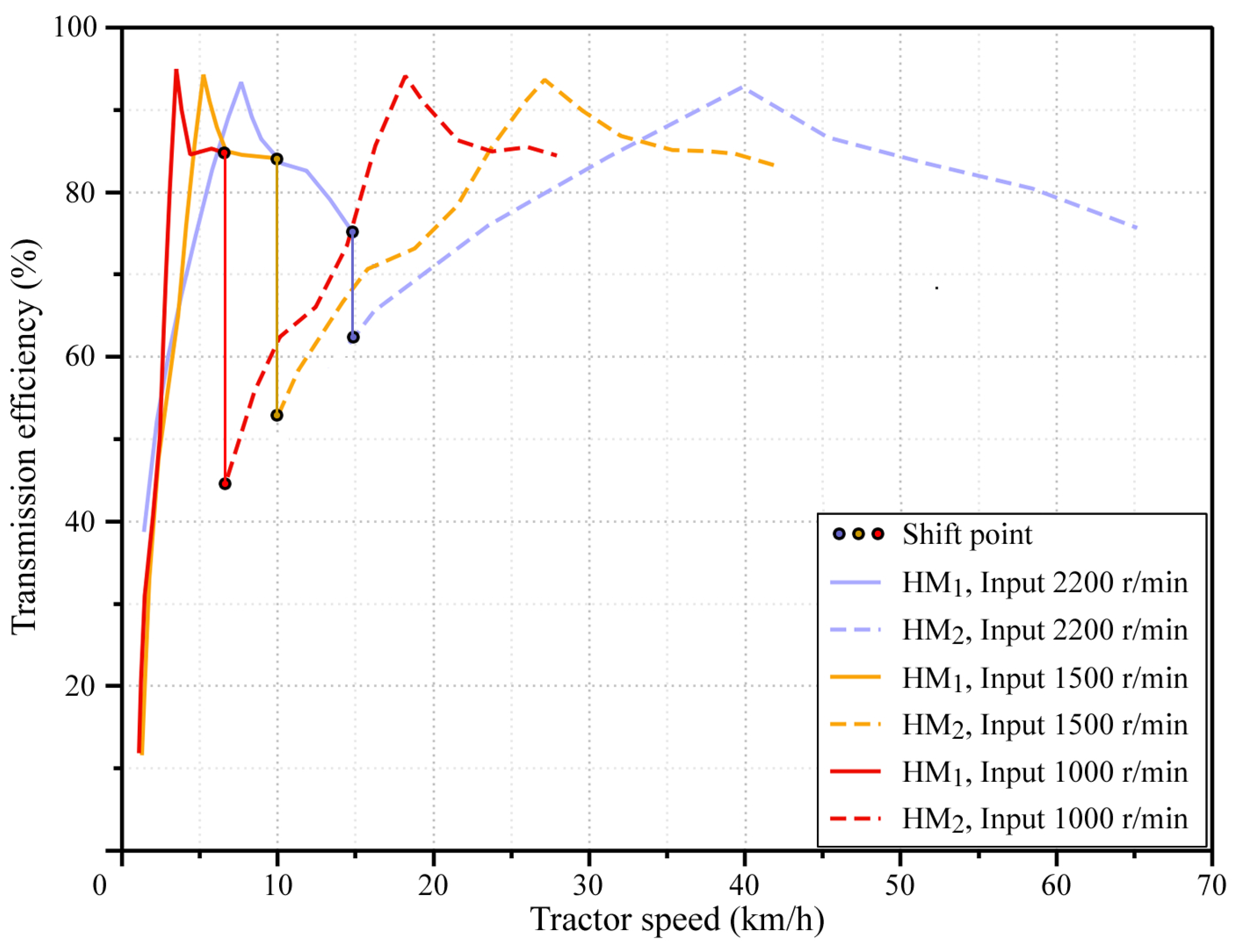
Figure 12. Full load efficiency of 2-range HMT.
Applsci 15 12576 g012
The efficiency of the 2-range HMT under partial load is shown in Figure 13. It can be seen from the figure:
(1)
The optimal efficiency point of the 2-range HMT at 8 km/h shifts to the upper right corner of the efficiency map, corresponding to the high-power output region of the HMT. This adjustment balances the HMT’s energy consumption with the tractor’s power output. In contrast, the 4-range HMT exhibits an optimal operating speed of 6 km/h under heavy load conditions.
(2)
Unlike the 4-range HMT, the 2-range HMT features a broad speed regulation range within a single range, eliminating the distinct ‘U’-shaped profile typically observed in its efficiency and fuel consumption distribution.
(3)
The 2-range HMT exhibits significant efficiency variations in the transitional zone between its two ranges. This indicates that efficiency differences before and after shifting must be accounted for in the development of HMT control strategies, both under full load and partial load conditions. Failure to do so can result in abrupt fluctuations in engine torque during shifts.
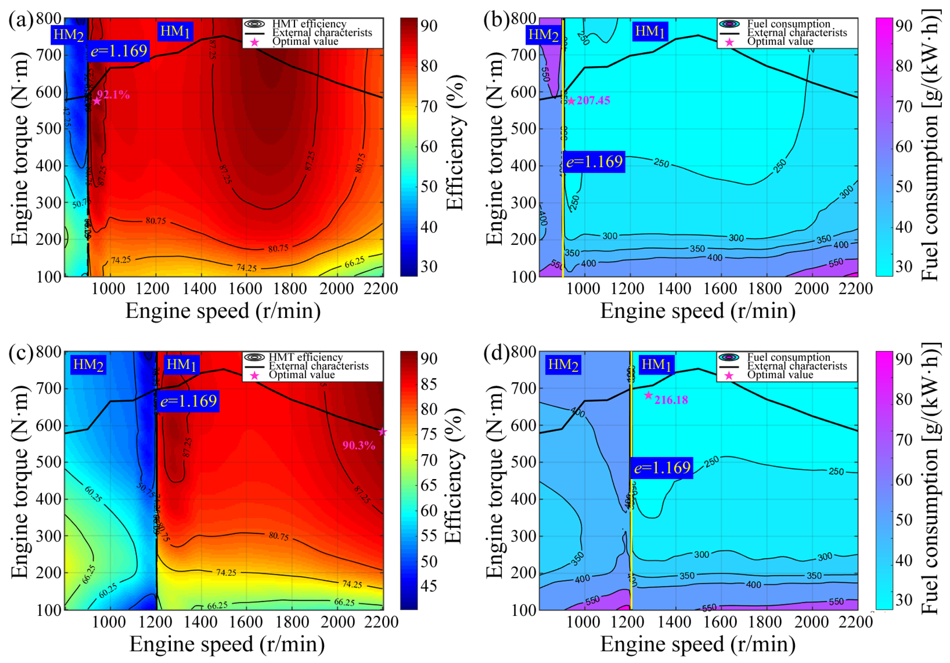
Figure 13. Transmission efficiency and fuel consumption of 2-range HMT: (a) Part load efficiency at 6 km/h; (b) Fuel consumption at 6 km/h; (c) Partial load efficiency at 8 km/h; (d) Fuel consumption at 8 km/h.
Applsci 15 12576 g013

4.2. Comparison with Other Tractor HMTs

In the prior comparison, the input power of both the Case New Holland 4-range HMT and 2-range HMT was standardized to 132.5 kW to ensure fairness. However, their actual power specifications differ: the design power of the Case New Holland 4-range HMT is 185 kW, whereas the 2-range HMT serves as its low-power variant, with a typical input power of 110 kW. To facilitate comparison with other commercial transmissions, the power ratings of the two Case New Holland HMT models were readjusted to their respective actual values—185 kW and 110 kW—and their full load efficiencies were recalculated. The HMT full load efficiency values used for comparison are derived from Fendt’s Vario [27], Hofer’s VDC [22], and Renius’ target efficiency for HMT tractors exceeding 100 kW [27]. As the efficiency values reported by Fendt and Renius included the rear axle, they were adjusted to HMT efficiency by incorporating a rear axle efficiency factor of 95%. This adjustment ensures consistent comparability across the data. The efficiency of these HMTs mentioned above is shown in Figure 14, and we explain it as follows:
(1)
The efficiency of HMT can surpass that of power-shift transmissions in energy consumption only if it exceeds the target efficiency established by Renius—a goal that presents significant challenges. To date, aside from Fendt’s Vario, few HMTs have fully achieved this standard. The Vario transmission employs a unique 2Z-X(A) planetary output coupled configuration, featuring 45 variable bent axis units co-developed by Fendt and Sauer Sundstrand. This design enables the HMT to maintain high efficiency across a broad speed ratio range. Due to the technical complexity involved, most existing HMTs instead utilize a multi-range planetary input-coupled configuration. Further research is needed to determine whether the 2Z-X(B) configuration can be integrated with the planetary output coupled setup.
(2)
Both Case New Holland and Hofer’s HMT employ planetary input-coupled configurations. In comparison to Vario, their efficiency curves display a distinct hump shape. while this configuration does not fully adhere to the standard proposed by Renius, it attains the target efficiency within the mid-range of each range and outperforms Vario.
(3)
Unlike Hofer’s VDC, Case New Holland and Fendt’s HMT systems lack a Hydrostatic starting range; instead, they employ a power-split range to facilitate tractor startup, thereby simplifying the HMT structure.
(4)
Despite differing tractor design speeds, Case New Holland’s 4-range HMT and Hofer’s VDC demonstrate consistent efficiency variation patterns, with the former achieving superior maximum efficiency. While the efficiency within the key operational speed range has been optimized for Case New Holland’s 2-range HMT, its overall performance remains relatively low. This is attributed to the smaller number of ranges and lower application power, resulting in a larger hydrostatic power portion and a higher basic energy consumption portion.
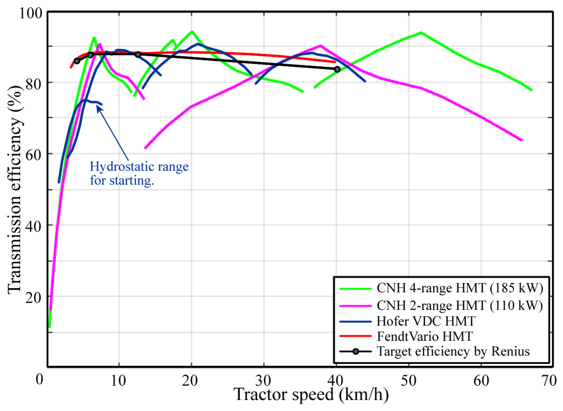
Figure 14. Efficiency comparison of tractor HMTs.
Applsci 15 12576 g014
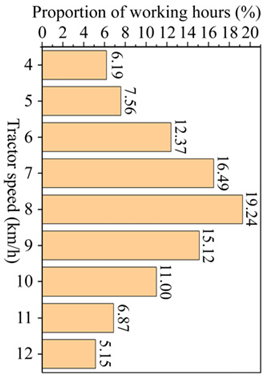
As indicated by Equation (16), the fuel consumption of the HMT system is influenced by both the transmission efficiency of the HMT and the coordinated control strategy between the HMT and the engine. As previously noted, tractors operate within the speed range of 4–12 km/h for 68% of their lifecycle, a range where heavy-duty operations such as plowing and rotary tillage are most prevalent. A widely employed control strategy during heavy-load operations is load-adaptive control, which maintains constant engine power output by adjusting the HMT ratio. This approach prevents tractor overload and minimizes power wastage. Assuming the engine operates in this control mode near its rated power point, fuel consumption comparisons can be made using publicly available HMT full-load efficiency data. For the HMT depicted in Figure 14, the manufacturer has not fully disclosed the engine specifications it employs. However, based on current engine technology standards, its specific fuel consumption under rated operating conditions typically ranges from 220 to 240 g/(kW·h). To illustrate, consider two examples: the WP6T180E21 engine supplied by the authors for the Case New Holland HMTs, which exhibits a specific fuel consumption of 221 g/kWh under rated conditions, and the MAN D0826LE531 engine provided by Fendt for the Vario HMT, with a corresponding value of 236 g/(kW·h). To ensure a fair comparison, we have standardized the specific fuel consumption of all HMTs at 230 g/(kW·h) under rated operating conditions. Using this standardized value, we calculated the fuel consumption of each HMT tractor during heavy load operation via Equation (16), with results presented in Table 1. The table details the proportion of tractor operating time across various speeds within the 4–12 km/h range, derived from data in Ref. [28]. To more accurately assess the fuel economy of HMT, we employed the following weighted method to calculate tractor fuel consumption:
g w = s p = 4 12 g t s p ω s p
where g w is the weighted fuel consumption of the tractor, g/(kW·h); s p is the tractor speed, km/h; ω is the weighting coefficient, %.
An interesting observation emerges from the data: apart from Fendt Vario, the fuel consumption of Case New Holland’s 4-range HMT and 2-range HMT, along with Hofer’s VDC HMT, consistently falls within the range of 276–277 g/(kW·h). As previously noted, Vario employs a highly specialized planetary output coupled design and a proprietary high-efficiency hydraulic system, distinguishing it as one of the few HMTs meeting the Renius standard. In contrast, the remaining three HMTs utilize conventional planetary input-coupled configurations. While their full-load efficiency curves exhibit significant differences in shape, their actual fuel consumption levels are nearly identical. Given that these HMTs represent fully optimized, mature commercial products, this consistency cannot be attributed to chance. Consequently, from a lifecycle perspective, the 2Z-X(B) HMT achieves fuel economy equivalent to that of the 2Z-X(A) HMT.

5. Conclusions

This study analyzes the energy consumption characteristics of HMT systems utilizing 2Z-X(B) planetary gear sets, using the 4-range and 2-range tractor HMTs from Case New Holland as case examples. The following conclusions were derived:
(1)
Using the pump-to-motor displacement ratio e = 0 as the boundary, parasitic power exists on the low-speed side of the HMT within the same range. This results in the HMT’s efficiency being higher on the high-speed side than on the low-speed side across all ranges, regardless of whether it is a 2-range or 4-range HMT. As engine speed increases, the friction energy loss due to viscous damping diminishes the aforementioned efficiency differences in the 4-range HMT; however, the 2-range HMT consistently retains this disparity.
(2)
As there is no hydrostatic range, the hydrostatic power portion of this type of HMT approaches 100% upon startup. During the transmission design phase, it must be ensured that the hydrostatic power portion of the HMT decreases to a lower level at the minimum field operating speed. Typically, this operating speed corresponds to 4 km/h at rated engine speed.
(3)
Regardless of whether it is a 2-range or 4-range HMT, tractor fuel consumption at the same speed and range varies with changes in pump displacement. This indicates that efficiency characteristics exert a more significant influence on tractor fuel economy than the engine’s inherent fuel consumption. Consequently, developing an efficiency-prioritized HMT control strategy is feasible.
(4)
The 2-range HMT has a simpler structure compared to the 4-range HMT; however, its efficiency exhibits significant variation before and after a range shift. Despite the transmission ratio remaining constant pre- and post-shift, the torque fluctuations resulting from efficiency changes can affect engine performance. This necessitates careful consideration when developing HMT shift control strategies and speed regulation approaches.
(5)
The optimal engine speed and HMT displacement ratio vary across different ranges as tractor speed changes. When tractor speed reaches 6 km/h, the optimal efficiency point of the 4-range HMT shifts to the high-power region, enabling the tractor to perform heavy-duty operations like ploughing with minimal fuel consumption. In contrast, the ideal heavy-load operating speed for the 2-range HMT is 8 km/h. During the transmission design phase, engineers should analyze local tractor operating conditions to optimize HMT efficiency at typical operating speeds.
(6)
When operating at the same tractor speed and HMT range, the 4-range HMT exhibits a pronounced ‘U’-shaped characteristic in its efficiency and fuel consumption distribution. This pattern arises from variations in the hydrostatic power portion as engine speed changes. In contrast, due to the broader speed range of each individual range, the 2-range HMT does not display a comparable efficiency and fuel consumption profile.
(7)
The HMT utilizing 2Z-X(B) planetary gear sets demonstrates superior transmission performance, achieving peak efficiency exceeding 90%. Its efficiency curve exhibits a hump-like shape, analogous to that of traditional HMT systems based on 2Z-X(A) planetary gear sets. Theoretically, 2Z-X(B) can be decomposed into two variants of 2Z-X(A), which likely explains the comparable performance between the two HMT types. Unlike Fendt’s Vario, the efficiency of HMT based on the 2Z-X(B) planetary gear set does not fully meet Renius’ proposed standards; however, it exhibits significantly higher local efficiency than Vario under specific operating conditions. Multi-range technology and planetary output coupled technology may represent viable approaches to further reduce energy consumption in 2Z-X(B)-based HMT systems.
(8)
A key finding of this study indicates that, when evaluated from a full lifecycle perspective, tractors equipped with 2Z-X(B) HMT demonstrate comparable fuel economy to those equipped with 2Z-X(A) HMT.
HMT based on the 2Z-X(B) planetary gear set demonstrates superior energy consumption characteristics, regardless of whether it is configured as a 4-range or 2-range system. Regarding causality, the hydrostatic power portion of the HMT dictates its efficiency profile, which in turn directly influences the fuel economy of tractors. Leveraging the insights derived from this study—including the performance distinctions between 2-range and 4-range HMTs—engineers can more precisely optimize HMT efficiency and develop effective energy-saving control strategies.
This article concludes by emphasizing that it presents a theoretical study, with no final experimental verification having been performed. When applying the findings of this study, it is crucial to note that the model does not account for efficiency fluctuations in gear pairs and bearings during operation; instead, these are uniformly converted into the meshing efficiency of gear pairs and treated as constant values. While the accuracy of the high-energy-consumption hydraulic system model was ensured using real experimental data provided by the manufacturer, this does not validate that the simplified model for gear pairs and bearings will not significantly affect overall calculation results. Such impacts must be confirmed through experimental methods in future research.

Author Contributions

Conceptualization: G.W.; Data curation: G.W.; Formal analysis: F.G. and Y.K.; Funding acquisition: G.W.; Investigation: F.G., Y.K., F.L., N.L. and Z.J.; Methodology: Y.Z.; Project administration: G.W.; Resources: G.W.; Software: F.G. and Y.K.; Supervision: G.W.; Validation: Y.K.; Visualization: F.G. and Y.K.; Writing—original draft: F.G., Y.K., F.L., N.L. and Z.J.; Writing—review & editing: G.W. and Y.Z. All authors have read and agreed to the published version of the manuscript.

Funding

This work was supported by the Shandong Province Agricultural Machinery R&D, Manufacturing, Promotion and Application Integration Pilot Project [grant number NJYTHSD-202302] and the Shandong Provincial Natural Science Foundation [grant number ZR2020QE163].

Institutional Review Board Statement

Not applicable.

Informed Consent Statement

Not applicable.

Data Availability Statement

The data presented in this study are available on request from the corresponding author.

Conflicts of Interest

Author Fengping Liu was employed by the company Shandong Weifang Luzhong Tractor Co., Ltd. The remaining authors declare that the re-search was conducted in the absence of any commercial or financial relationships that could be construed as a potential conflict of interest.

References

  1. Wu, Y.; Zhou, Z.; Yan, X. Unified modeling of a tractor performance prototype based on ontology. Trans. Can. Soc. Mech. Eng. 2022, 46, 477–489. [Google Scholar] [CrossRef]
  2. Li, B.; Pan, J.; Li, Y.; Ni, K.; Huang, W.; Jiang, H.; Liu, F. Optimization method of speed ratio for power-shift transmission of agricultural tractor. Machines 2023, 11, 438. [Google Scholar] [CrossRef]
  3. Li, J.; Zhai, Z.; Song, Z.; Fu, S.; Zhu, Z.; Mao, E. Optimization of the transmission characteristics of an HMCVT for a high-powered tractor based on an improved NSGA-II algorithm. Proc. Inst. Mech. Eng. Part D J. Automob. Eng. 2022, 236, 2831–2849. [Google Scholar] [CrossRef]
  4. Wang, J.; Xia, C.; Fan, X.; Cai, J. Research on transmission characteristics of hydromechanical continuously variable transmission of tractor. Math. Probl. Eng. 2020, 2020, 6978329. [Google Scholar] [CrossRef]
  5. İnce, E.; Güler, M.A. On the advantages of the new power-split infinitely variable transmission over conventional mechanical transmissions based on fuel consumption analysis. J. Clean. Prod. 2020, 244, 118795. [Google Scholar] [CrossRef]
  6. Macor, A.; Rossetti, A. Fuel consumption reduction in urban buses by using power split transmissions. Energy Convers. Manag. 2013, 71, 159–171. [Google Scholar] [CrossRef]
  7. Wang, G.; Zhao, Y.; Song, Y.; Xue, L.; Chen, X. Optimizing the fuel economy of hydrostatic power-split system in continuously variable tractor transmission. Heliyon 2023, 9, e15915. [Google Scholar] [CrossRef]
  8. Seeger, J. Wirkungsgraduntersuchung des systems “Dieselmotor-Leistungsverzweigtes Getriebe”. Öl Hydraul. Pneum. 2001, 45, 672–677. [Google Scholar]
  9. Ahn, S.; Choi, J.; Kim, S.; Lee, J.; Choi, C.; Kim, H. Development of an integrated engine-hydro-mechanical transmission control algorithm for a tractor. Adv. Mech. Eng. 2015, 7, 1687814015593870. [Google Scholar] [CrossRef]
  10. Ramdan, M.I.; Stelson, K.A. Optimal design of a power-split hybrid hydraulic bus. Proc. Inst. Mech. Eng. Part D J. Automob. Eng. 2016, 230, 1699–1718. [Google Scholar] [CrossRef]
  11. Bukashkin, A.Y.; Dobretsov, R.Y.; Galyshev, Y.V. Split transmission of tractor with automatic gearbox. Procedia Eng. 2017, 206, 1728–1734. [Google Scholar] [CrossRef]
  12. Rao, Z. Design of Planetary Gear Transmission, 2nd ed.; Chemical Industry Press Co., Ltd.: Beijing, China, 2019. [Google Scholar]
  13. Li, J.; Zhao, Y.; Zhai, Z.; Han, B.; Du, Y.; Wang, L.; Zhu, Z. Research on design and analysis method of the double planetary HMCVT based on high efficiency transmission. Agriculture 2020, 12, 1958. [Google Scholar] [CrossRef]
  14. Xia, Y.; Sun, D.; Qin, D.; Zhou, X. Optimisation of the power-cycle hydro-mechanical parameters in a continuously variable transmission designed for agricultural tractors. Biosyst. Eng. 2020, 193, 12–24. [Google Scholar] [CrossRef]
  15. Chen, Y.; Qian, Y.; Lu, Z.; Zhou, S.; Xiao, M.; Bartos, P.; Xiong, Y.; Jin, G.; Zhang, W. Dynamic characteristic analysis and clutch engagement test of HMCVT in the high-power tractor. Complexity 2021, 2021, 8891127. [Google Scholar] [CrossRef]
  16. Liu, M.; Li, W.; Xu, L.; Li, Y.; Zhao, T.; Hou, S. Coordinated dual-rolling control of shifting in HMCVT based on KF-MPC algorithm with anti-disturbance capabilities. Comput. Electron. Agric. 2024, 227, 109561. [Google Scholar] [CrossRef]
  17. Rossetti, A.; Macor, A. Multi-objective optimization of hydro-mechanical power split transmissions. Mech. Mach. Theory 2013, 62, 112–128. [Google Scholar] [CrossRef]
  18. Rossetti, A.; Macor, A.; Scamperle, M. Optimization of components and layouts of hydromechanical transmissions. Int. J. Fluid Power 2017, 18, 123–134. [Google Scholar] [CrossRef]
  19. Nguyen, V.T. Study on Dynamic Characteristics of Hydro Mechanical Continuously Variable Transmission of Tractor. Ph.D. Thesis, Nanjing Agricultural University, Nanjing, China, 2013. [Google Scholar]
  20. Zhang, Z.; Li, X.; Peng, Z.; Jing, C.; Yang, S.; Chen, Z. Full-condition efficiency model and power loss analysis of hydro-mechanical CVT. Trans. CSAE 2024, 40, 48–58. [Google Scholar] [CrossRef]
  21. Zhang, G.; Wang, K.; Xiao, M.; Zhou, M. HMCVT steady state transmission efficiency based on HST-EGT torque ratio. Trans. CSAM 2021, 52, 533–541. [Google Scholar] [CrossRef]
  22. Wang, G. Study on Characteristics, Control and Fault Diagnosis of Tractor Hydro-Mechanical CVT. Ph.D. Thesis, Nanjing Agricultural University, Nanjing, China, 2014. [Google Scholar]
  23. Rossetti, A.; Macor, A. Control strategies for a powertrain with hydromechanical transmission. Energy Procedia 2018, 148, 978–985. [Google Scholar] [CrossRef]
  24. D’Andrea, D.; Risitano, G.; Alberti, F. Fuel consumption reduction and efficiency improvement in urban street sweeper using power split with lockup clutch transmission. Appl. Sci. 2022, 12, 10160. [Google Scholar] [CrossRef]
  25. Cammalleri, M.; Rotella, D. Functional design of power-split CVTs: An uncoupled hierarchical optimized model. Mech. Mach. Theory 2017, 116, 294–309. [Google Scholar] [CrossRef]
  26. Rotella, D.; Cammalleri, M. Direct analysis of power-split CVTs: A unified method. Mech. Mach. Theory 2018, 121, 116–127. [Google Scholar] [CrossRef]
  27. Renius, K.T. Fundamentals of Tractor Design, 1st ed.; Springer Nature: Cham, Switzerland, 2020. [Google Scholar]
  28. Meyer, H.J. Fahrzeuggetriebetechnik Getriebe in Traktoren; Technische Universität Berlin: Berlin, Germany, 2009. [Google Scholar]
Figure 1. 2Z-X series planetary gear set [12].
Applsci 15 12576 g001
Figure 2. Case New Holland 4-range tractor HMT [27].
Applsci 15 12576 g002
Figure 3. Case New Holland 2-range tractor HMT [27].
Applsci 15 12576 g003
Figure 4. Efficiency map of pump and motor: (a) Mechanical efficiency of pump at displacement 1 · V p m a x ; (b) Volumetric efficiency of pump at displacement 1 · V p m a x ; (c) Mechanical efficiency of pump at displacement 0.75 · V p m a x ; (d) Volumetric efficiency of pump at displacement 0.75 · V p m a x ; (e) Mechanical efficiency of pump at displacement 0.5 · V p m a x ; (f) Volumetric efficiency of pump at displacement 0.5 · V p m a x ; (g) Mechanical efficiency of pump at displacement 0.25 · V p m a x ; (h) Volumetric efficiency of pump at displacement 0.25 · V p m a x ; (i) Mechanical efficiency of motor at displacement 1 · V m ; (j) Volumetric efficiency of motor at displacement 1 · V m .
Applsci 15 12576 g004
Figure 5. Energy consumption calculation model for tractor HMT.
Applsci 15 12576 g005
Table 1. Fuel comparison of tractor HMTs under heavy load operation (4–12 km/h).
Tractor Speed (km/h)Fuel Consumption of HMT Tractor [g/(kW·h)]Weighting Coefficient (%)
CNH 4-Range HMTCNH 2-Range HMTHofer VDC HMTFendt Vario HMTIdeal HMT by Renius
419.2220.6622.1416.4016.49Applsci 15 12576 i001
521.0822.6324.0619.7319.91
631.8233.9735.8732.1332.19
742.4742.4444.8642.7342.92
852.2450.8050.2549.7850.07
942.3941.6639.4139.1039.34
1031.3530.8528.3328.4628.61
1120.0019.4417.7517.8217.88
1215.5914.9613.4313.3813.41
Weighted fuel consumption
[g/(kW·h)]
276.17277.42276.09259.53260.81
Disclaimer/Publisher’s Note: The statements, opinions and data contained in all publications are solely those of the individual author(s) and contributor(s) and not of MDPI and/or the editor(s). MDPI and/or the editor(s) disclaim responsibility for any injury to people or property resulting from any ideas, methods, instructions or products referred to in the content.