Article

Study of a High-Power, Long-Pulse-Width Acousto-Optical Q-Switched 1064 nm Laser Based on a Multi-Pass Cavity

1
School of Physics and Optoelectronic Engineering, Beijing University of Technology, Beijing 100124, China
2
Beijing Engineering Research Center of Laser Technology, Beijing University of Technology, Beijing 100124, China
3
Key Laboratory of Trans-Scale Laser Manufacturing Technology, Beijing University of Technology, Ministry of Education, Beijing 100124, China
4
National Key Laboratory of Chemical and Physical Power Sources, Tianjin Institute of Power Sources, Tianjin 300384, China
5
National Key Laboratory of Electromagnetic Space Security, Tianjin 300308, China
*
Authors to whom correspondence should be addressed.
Appl. Sci. 2025, 15(23), 12536; https://doi.org/10.3390/app152312536
Submission received: 31 October 2025 / Revised: 22 November 2025 / Accepted: 25 November 2025 / Published: 26 November 2025
(This article belongs to the Section Optics and Lasers)

Abstract

A high-power, long-pulse-width acousto-optical Q-switched 1064 nm laser based on a multi-pass cavity (MPC) is reported in this paper. First, a plano-concave MPC structure satisfying the Q-preserving configuration was designed and introduced into an acousto-optical Q-switched plano-plano cavity Nd:YAG laser, extending the original laser cavity length by 1200 mm. The laser achieved a maximum average output power of 123.6 W with a repetition rate of 10 kHz. At this power level, the laser pulse width was broadened to 157.5 ns, which can be compared to 82.5 ns without the MPC structure, achieving a broadening ratio of 90.9%. The beam quality factors were M x 2 = 10.75 in the horizontal direction and M y 2 = 11.37 in the vertical direction. The experimental results demonstrate that inserting an MPC into the cavity is an effective method for broadening the pulse width of nanosecond lasers.

1. Introduction

Nanosecond pulsed lasers play significant roles in various fields, such as material processing [1,2,3], LIDAR [4,5], space communications [6,7], scientific research [8], and biomedicine [9]. In the field of laser processing [10], there are differences in the optimal laser pulse widths required for different processed materials, and this type of laser can significantly improve processing efficiency and product quality by adapting different pulse width parameters. In laser marking and etching applications [11], a narrow pulse width is suitable for deep marking by virtue of its high peak power, while a long pulse width is more suitable for surface etching due to its low-peak-power characteristics. In the design of coherent lidar systems, a transform-limited pulse of about 500 ns is required to achieve a velocity resolution of 1 m/s for a single measurement [12]. In nanosecond lasers, Q-switching techniques produce typical laser pulse widths in the range of 10 to 100 ns; however, in many applications, there is a need to achieve high single-pulse energies and low peak powers using long-nanosecond pulsed laser sources, which can reduce laser-induced damage and achieve narrowband laser output [13].
In Q-switched lasers, the pulse width is determined by parameters such as gain, loss, and cavity length. The principle of gain adjustment involves modulating the pump power to alter the population inversion level in the gain medium, thereby influencing the formation and energy release of the laser pulse. Loss adjustment, on the other hand, relies on a Q-switch to control intracavity loss and modify the cavity Q-factor, enabling the initiation and release control of the pulse. However, both methods exhibit significant drawbacks: gain adjustment offers a narrow and nonlinear pulse width tuning range, is susceptible to pump fluctuations and thermal drift leading to poor stability, and suffers from coupling with output energy, making independent optimization difficult. Loss adjustment only allows fine-tuning within the inherent pulse width range of the cavity configuration; excessive adjustment significantly reduces laser efficiency or even extinguishes the pulse [14,15,16,17]. The most effective way to adjust the pulse width in such lasers is to adjust the cavity length, thereby increasing the output laser pulse width and realizing a tunable pulse width. However, this method makes the laser bulky and difficult to realize for applications and reduces the stability of the resonant cavity. The multi-path cavity (MPC), which can provide long optical paths in a small footprint while keeping the Q-parameters of the light passing through them constant, have been used for precise optical loss measurements, stimulated Raman scattering, and long-path absorption spectroscopy, among others [18]. In 2021, Zhang Zhenxi et al. [19] designed an MPC system with an adjustable optical range function in combination with MPC for the different concentration of gases in infrared laser gas absorption detection technology with different demands for detection sensitivity. In research related to lasers, MPCs were mostly used in picosecond and femtosecond lasers to reduce the repetition rate and compress the pulse width to increase the single pulse energy. In 2023, Alan Omar et al. [20] used a concave–convex-cavity MPC to broaden the spectral bandwidth of the output laser of a thin disk regenerative amplifier from 2.1 nm (670 fs, 210 W) to 24.5 nm (134 fs, 203 W) with a transmission efficiency of 96%, preserving the beam quality and good spectral uniformity. Li et al. (2024) [21] used a plano-concave MPC combined with a solid lamella group to broaden the spectrum from 0.24 to 4.8 nm, and then used a grating pair for dispersion-compensated compression, which ultimately compressed the pulse width of 10.7 ps to 483 fs, with a compression ratio of 22 and an average output power of 44.2 W. In 2019, Song Yanjie et al. [22] used the MPC technique for the first time to represent a compact long-nanosecond-pulse laser with continuous tunability from 160 to 1000 ns at a repetition rate of 10 kHz; with a 560 ns pulse width, the average output power reached 10.6 W and the beam-quality factor M2 was 1.45.
In summary, there remains a research gap in the field of high-power long-pulse-width nanosecond-scale 1064 nm lasers. Consequently, a plano-plano cavity all-solid-state acousto-optical Q-switched 1064 nm laser was constructed to extend the cavity length by inserting an MPC into the resonant cavity, and the pulse width was broadened from 82.5~295 ns to 157.5~502.5 ns, and the pulse width broadening ratio was 90.9% at the maximum output power, demonstrating a clear broadening effect. At a repetition rate of 10 kHz, the laser achieved a maximum average output power of 123.6 W, with the beam quality factors of M x 2 = 10.75 in the horizontal direction and M y 2 = 11.37 in the vertical direction. To the best of our knowledge, this is the highest power achieved based on MPC for nanosecond-scale pulse width broadening.

2. Theoretical Analysis

The design of the MPC is of great importance as a crucial device for pulse width broadening. When designing the MPC, the following conditions need to be satisfied:
First, the two mirrors of the MPC need to remain parallel. If there is a tilt angle between the two mirrors of the MPC, the center of the circular spot distribution formed by the laser beam will shift. Therefore, a mirror tube is used in this study to ensure the parallelism of the two mirrors [23].
Second, injection and extraction of the laser beam on the MPC mirrors must be achieved. Since the mirror tube is needed to ensure the parallelism of the two mirrors, adding a mirror on the side of the MPC would block the beam path of the extraction mirror. Thus, a notch is cut directly into the mirror, where a notch width of 4 mm can effectively avoid spot overlap or beam leakage.
Third, the Q-preserving configuration of the MPC must be satisfied. When adjusting the MPC parameters, an incident beam with the correct position and angle of incidence will undergo multiple reflections before exiting. The trajectory formed by successive reflections of the beam observed on a given reference plane (on the end mirror) shows an elliptical or circular spot pattern. Under certain conditions, the MPC can keep the Q-parameters of the Gaussian beam constant [18].
A constant Q-parameter implies that due to the intracavity, periodic focusing and diffraction beam divergence effects cancel each other out. When the relationship is satisfied between the number n of round trips of the beam within the MPC, the angle θ between the front and back spots formed by the beam on the reference plane after each round trip, and the number m of semicircular arcs traversed by the reflected beam on one of the mirrors before the Q-parameter is converted back to its initial value,
n θ = m π ,
and the Q-parameter of the MPC remains unchanged. That is, when the angle θ between consecutive reflections of the beam is π multiplied by the ratio of two integers (m/n), the Gaussian Q parameter remains constant after n round trips.
When a concave mirror with a radius of curvature R of 400 mm is selected as the spherical mirror of the plano-concave MPC, the curves of the cavity length extension L with different values of m and n are shown in Figure 1. With a preliminary set MPC extension L of 1200 mm under the condition of a circular spot distribution, and with the number of semicircular arcs m = 2 and n = 6, the extension of the cavity length is exactly 1200 mm. In this case, the angle of the adjacent spots θ is π/3, and the distance between the two mirrors d is 100 mm.
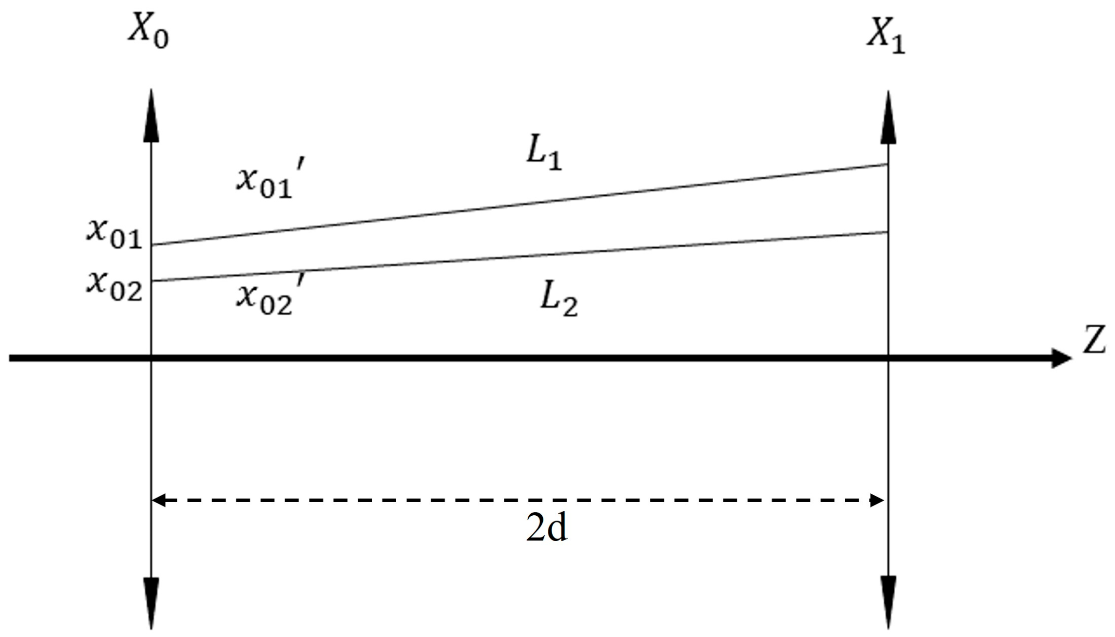
In the MPC design, in order to avoid interference and laser leakage during optical path adjustment affecting the experimental results, it is necessary to calculate the spot diameter to check whether there is any overlap or laser leakage in the transmission. The size of the reflected spots on the mirrors changes according to a certain law during the transmission of the laser inside the MPC. In order to obtain the size of the spot, a certain divergence angle beam edge laser can be tracked. According to the theory of near-axis laser propagation, the coaxial plano-concave cavity MPC system can be equated to a coaxial thin lens group with a focal length f, as shown in Figure 2. In the x-z plane, X0 and X1 represent equivalent coaxial thin lenses with focal length f, respectively, and the distance between the two mirrors is 2d. In the z-axis direction, assuming the edge incident rays are denoted as r1 and r2, the coordinates of the incident positions of the two lines in the x-axis direction are x 01 , x 02 , and the slopes are x 01 , x 02 , respectively, the diameters of the spots after n reflections [19] can be expressed by the following equation:
R L = x 01 x 02 cos n θ + d 2 f d x 01 x 02 + 2 f x 01 x 02 sin n θ .
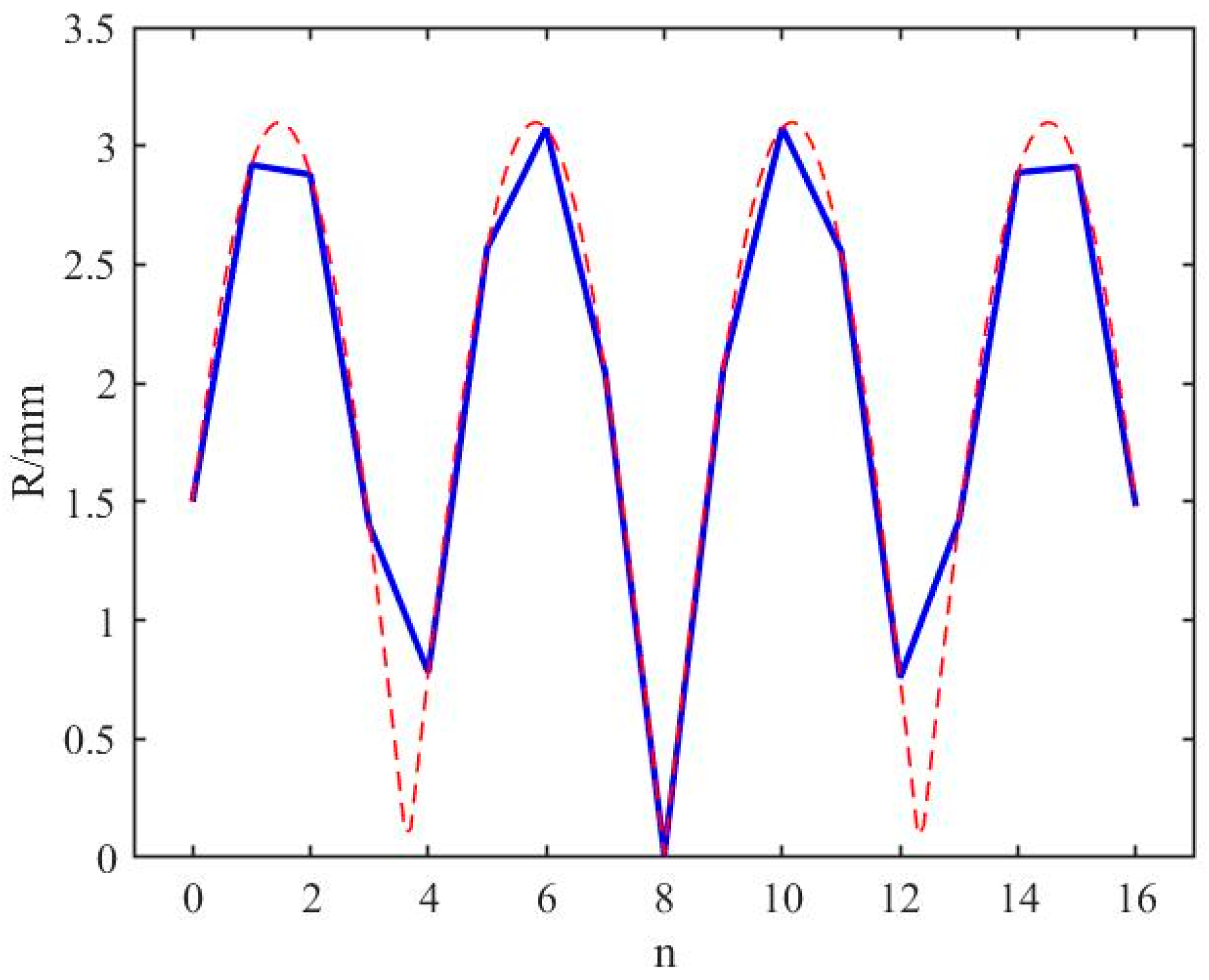
According to Equation (2), the spot diameter is mainly determined by several key parameters such as the initial beam diameter, the focal length of the mirrors, the spacing of the mirrors, the number of reflections, and the divergence angle. According to Equation (2), the approximate size of the beam at different positions within the MPC can be calculated. As shown in Figure 3, the distribution of spot sizes exhibits a trigonometric function pattern.

3. Experimental Setup

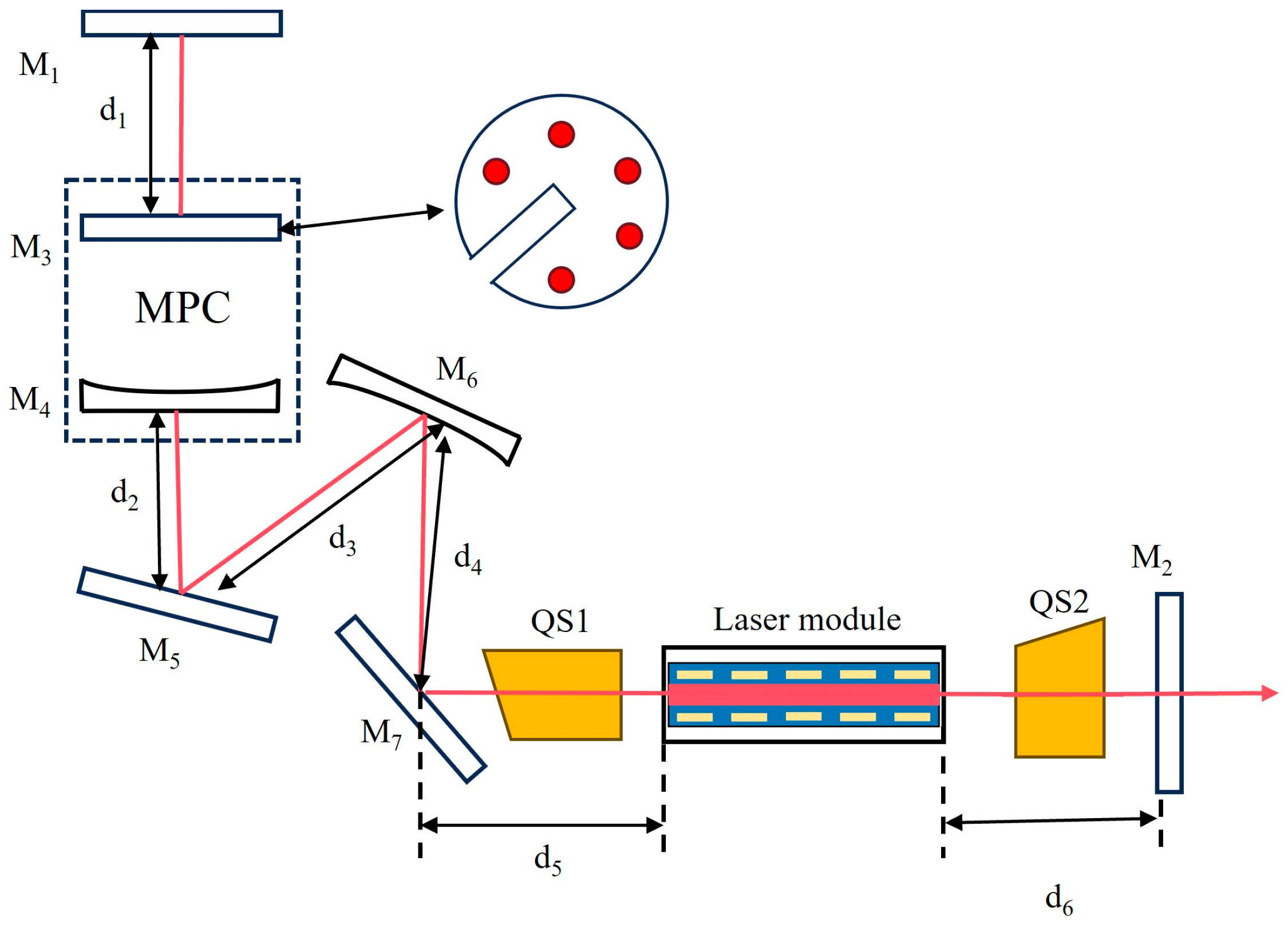
A pulse-width-tunable 1064 nm acousto-optic Q-switched laser was constructed, with its schematic diagram shown in Figure 4. The Nd:YAG rod used in the laser module was Ф4 × 100 mm with 0.6 at.% Nd-doped. The crystal end faces were anti-reflection (AR)-coated at 1064 nm to minimize Fresnel reflection. Two acousto-optical Q-switches (QS1 and QS2, GOOCH&HOUSEGO) were positioned on either side of the Nd:YAG module orthogonally, to improve the hold-off capacity, and driven synchronously by a single power supply. The Q-switches operated at a pulse repetition rate of 10 kHz, and both end faces of the Q-switches were coated for high transmission (HT) at 1064 nm and placed very close to the laser module.
M1, M3, M4, M5, and M6 were all high-reflection (HR)-coated for 1064 nm at 0° incidence (R > 99.5% @ 1064 nm, 0°). Among them, both M4 and M6 were concave mirrors with a radius of curvature R = 400 mm. The MPC was composed of M3 and M4, and it is mounted on a five-dimensional adjustment stage, allowing adjustments in x-axis, y-axis, and z-axis displacements, as well as pitch and deflection, to achieve relative angular alignment of the incident beam into the MPC. According to theoretical simulations, the beam needed to complete six round trips within the MPC to satisfy the Q-preserving configuration. However, during experiments, the beam exited through the mirror notch after only five round trips in the MPC, thus violating the Q-preserving configuration. The purpose of M5 and M6 was to compensate for one additional round trip, effectively adding a concave mirror with R = 400 mm and an additional optical path length of 2d = 200 mm within the cavity. Furthermore, since the output laser had an inclination in the x and y directions, mirrors M5 and M6 were also needed to level the beam in order to facilitate the construction of the optical path. A plane mirror M7 was HR-coated for 1064 nm at 45° incidence (R > 99.7% @ 1064 nm, 45°). The output coupler M2 was a plane mirror with a transmittance of 30% at 1064 nm. The distances shown in the figure were d1 = 25 mm, d2 = 80 mm, d3 = 120 mm, d4 = 80 mm, d5 = 170 mm, and d6 = 210 mm.
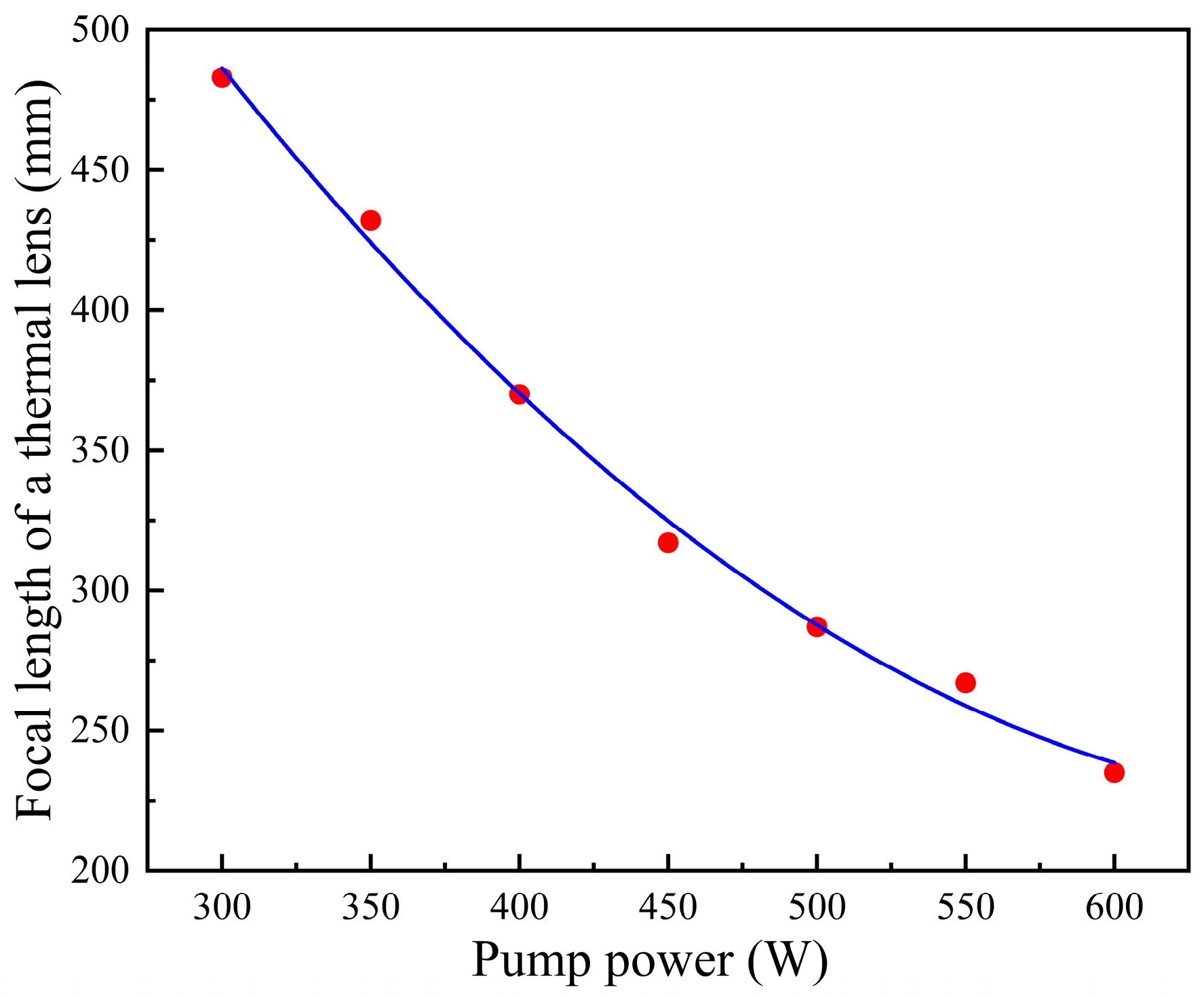
The focal length of the thermal lens was determined by expanding a probe laser beam and focusing it through the Nd:YAG crystal [24], with the results shown in Figure 5. During the continuous increase in the pump power, the thermal focal length value of the laser crystal exhibited a decreasing trend.
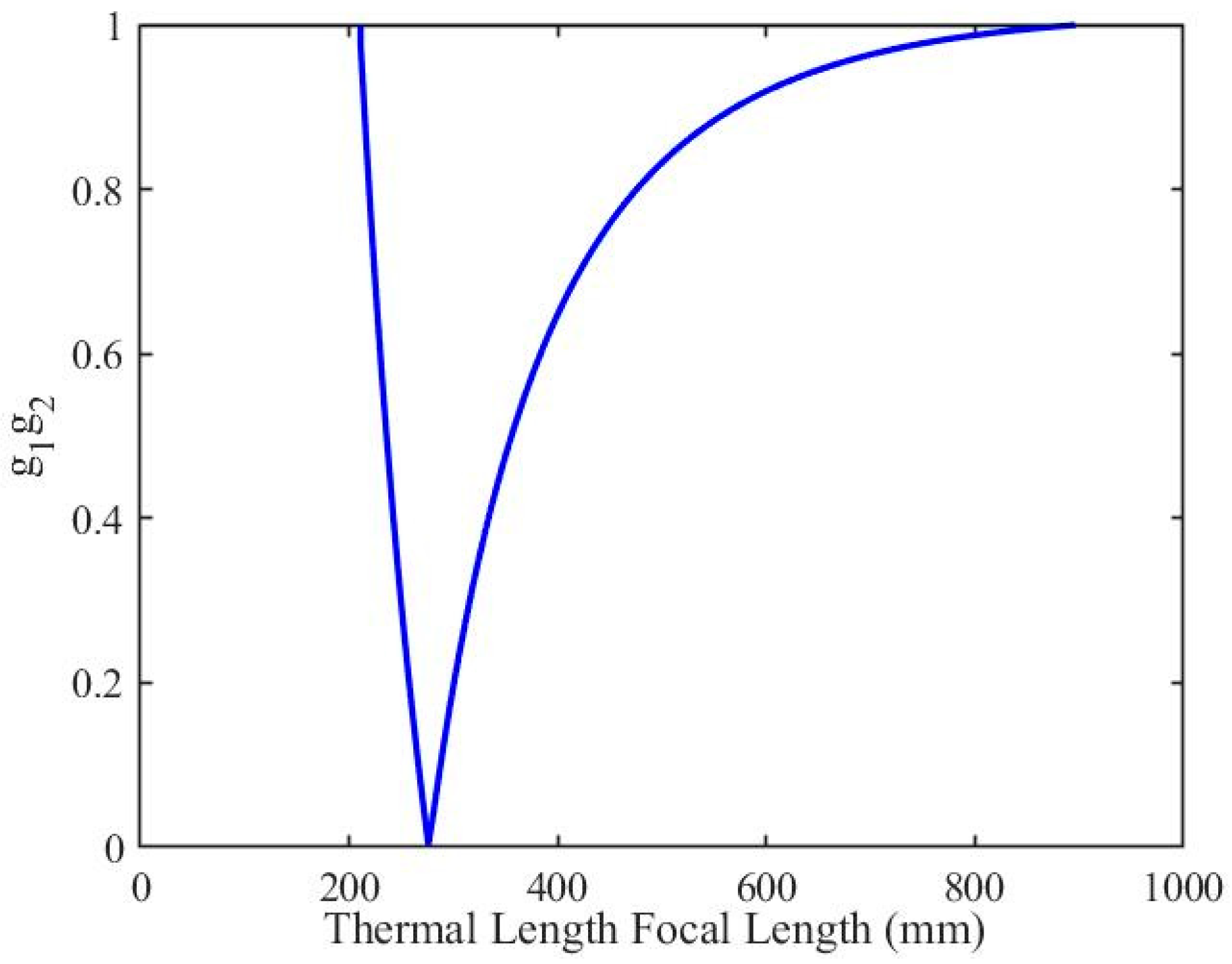
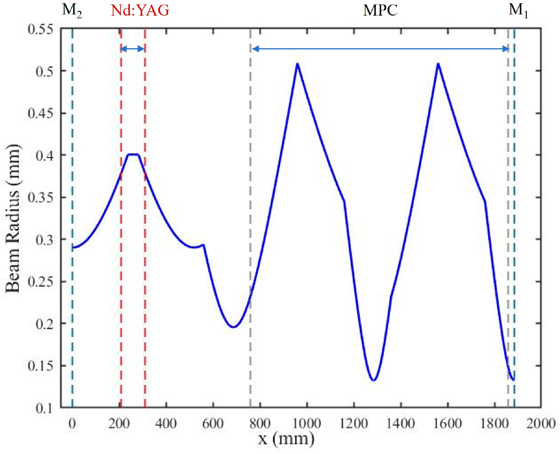
The stability zone distribution of the resonator shown in Figure 4 was simulated using MATLAB (Matlab For Windows R2024a), as presented in Figure 6. As the laser pump power increases, the thermal focal length decreases. With this reduction in the thermal focal length, the product of g1 ∗ g2 remained within the range of 0 to 1, indicating that the resonator operates stably across the entire pump power range. Furthermore, since an additional concave mirror M6 with a radius of curvature R = 400 mm is incorporated into the cavity to ensure the MPC satisfied the Q-preserving configuration, it is necessary to evaluate the energy concentration at the focal point of this mirror to avoid potential damage caused by excessive intracavity power. Figure 7 depicts the beam diameter of fundamental mode at any position within the cavity when the thermal lens focal length is 250 mm. As shown in the figure, due to the thermal lensing effect, the spot radius at both ends of the Nd:YAG module gradually decreases. The smallest beam spots occur at d3 positions marked in Figure 4. Although the MPC does not satisfy the Q-preserving configuration condition, the speckle pattern observed from the MPC reveals that, due to the compensating effect of the M6, the cavity-internal speckle exhibits a periodic focusing state.

4. Results and Discussion

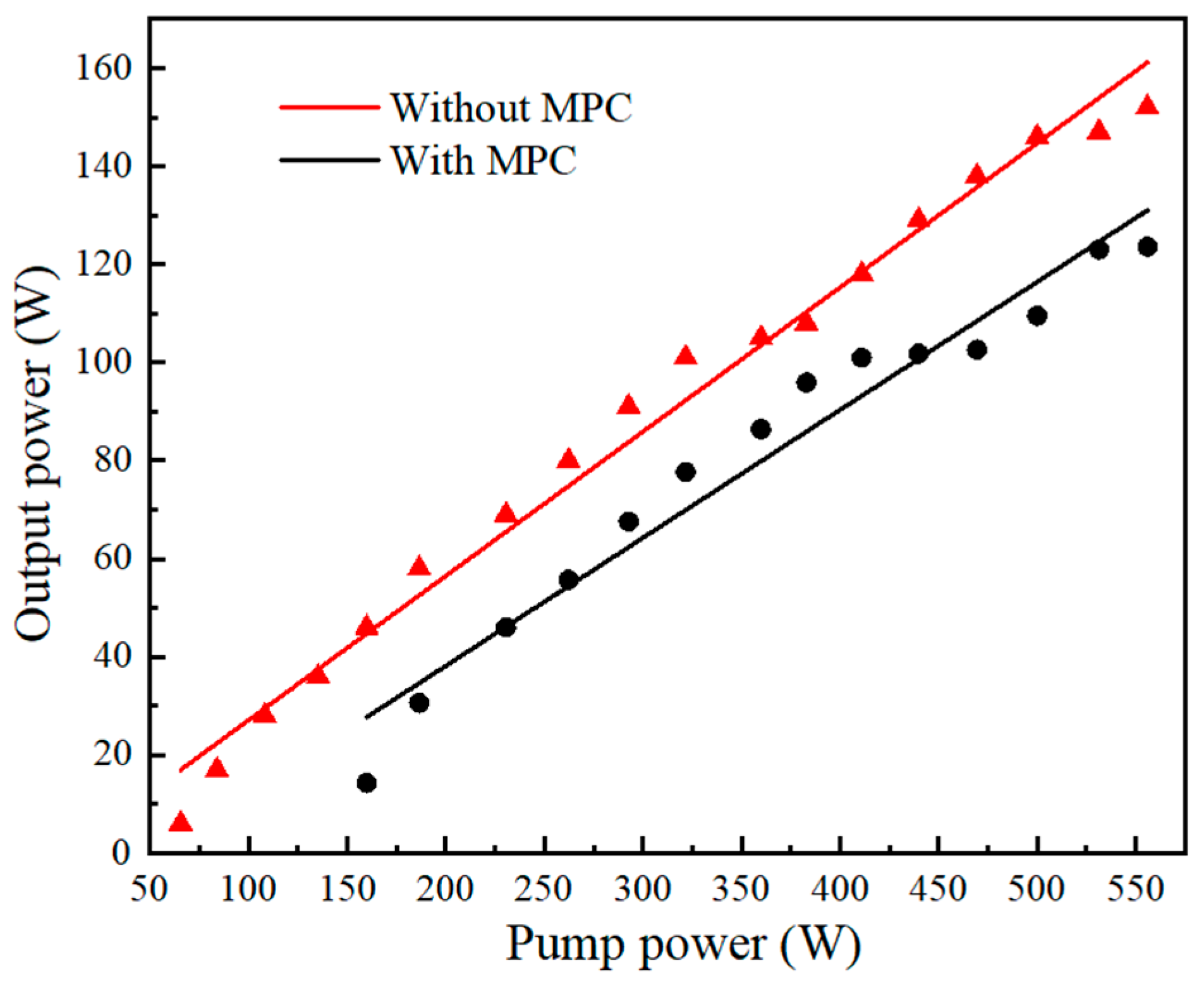
In this experiment, the curves of the average power of the 1064 nm laser versus the pump power with and without the MPC in the cavity were measured using a power meter (Ophir, FL600A-BB-65) (Jerusalem, Israel), and the results are shown in Figure 8. At a repetition rate of 10 kHz, the average power of the 1064 nm laser exhibited a linear increasing trend with the gradual increase in the pump power. In the figure, the red and black curves represent the output power curves without and with the MPC, respectively. At a repetition rate of 10 kHz, when the pump power reached its maximum value of 555.8 W, the maximum average output power without the MPC structure was measured to be 154 W, corresponding to an optical-to-optical conversion efficiency of 27.7%. When the MPC was inserted to extend the cavity length, the maximum average output power was 123.6 W, with an optical-to-optical conversion efficiency of 22.2%. The decrease in power was attributed to the reflection losses from the mirrors in the MPC structure and the additional mirrors M5~M7 within the cavity, as these mirrors lacked angle-specific coatings for the incident beams. Furthermore, the introduction of the MPC also increased the lasing threshold of the resonator.
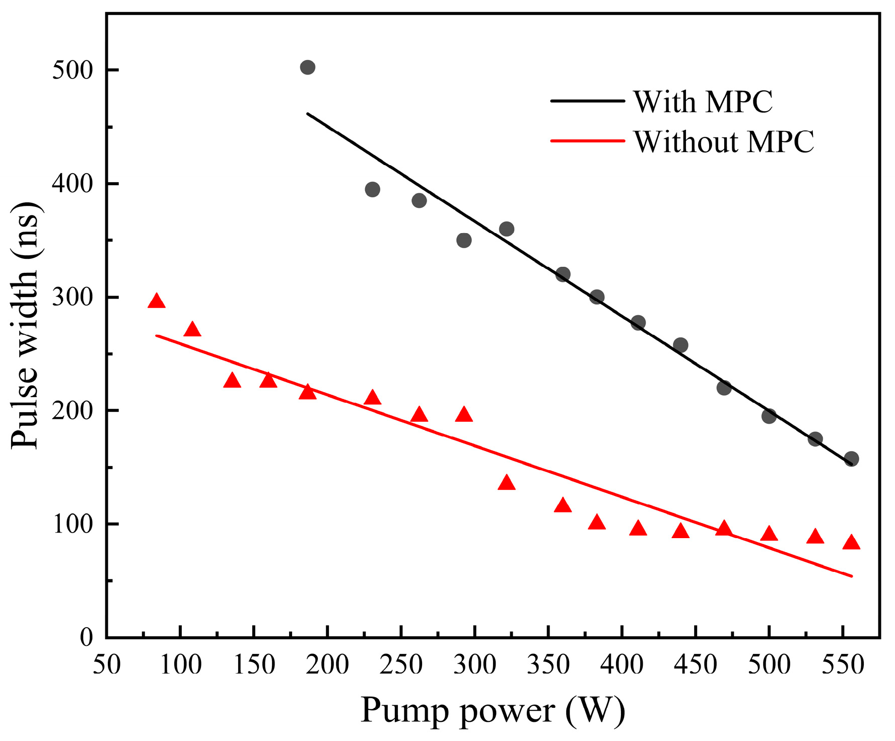
A photodetector (THORLABS, DET10A2) (Newton, NJ, USA) with an oscilloscope (Tektronix, TDS3054B) (Beaverton, OR, USA) was used to measure the pulse duration of the output laser. In order to verify the effectiveness of pulse width broadening by inserting the MPC into the cavity, the pulse width curves with and without MPC were compared, as shown in Figure 9. In the figure, the red curve represents the pulse width without the MPC, while the black curve corresponds to the pulse width with the MPC inserted. It can be observed that the laser pulse width continuously decreases as the pump power increases. Adjusting the pump power, the pulse width tuning range without the MPC was 295~82.5 ns. After inserting the MPC into the resonator, the pulse width tuning range was broadened to 502.5~157.5 ns. At the maximum pump power of 555.8 W, where the output power reaches its peak, the pulse widths with and without MPC were 157.5 and 82.5 ns, respectively, and the corresponding pulse width broadening ratio with the MPC inserted reached 90.9%, demonstrating a significant pulse broadening effect.
The beam intensity distribution and beam quality of the 1064 nm pulsed laser at its maximum output power were measured using a beam quality analyzer (DataRay, M2DU-200 Stage) (Redding, CA, USA), and the results are shown in Figure 10. As can be observed from Figure 10, the output laser exhibits good circular symmetry and strongly suggests a good Gaussian spatial mode. When the output power of the 1064 nm pulsed laser without the MPC reached its maximum of 154 W, the beam quality factors were measured to be M x 2 = 9.21 in the horizontal direction and M y 2 = 7.66 in the vertical direction. After inserting the MPC, with the output power of the 1064 nm pulsed laser at 123.6 W, the beam quality factors were M x 2 = 10.75 in the horizontal direction and M y 2 = 11.37 in the vertical direction. The slight decrease in the output beam quality with the introduction of the MPC structure is mainly due to the fact that the MPC structure is heated by the higher-order modes under the high power operation, which leads to aberrations in the optical lenses in the MPC structure and thus reduces the quality of the beam modes, and this can be improved by designing water-cooled structures for the MPC.

5. Conclusions

A pulse-width-tunable all-solid-state 1064 nm acousto-optical laser based on an MPC was constructed. The MPC structure was first designed according to the Q-preserving configuration, and a spherical mirror with a radius of curvature R = 400 mm and an extension length of 100 mm was employed to compensate for the missing optical path in the MPC. At a pump power of 555.8 W and a pulse repetition rate of 10 kHz, the output powers of the 1064 nm laser were 154 and 123.6 W without and with the MPC structure, respectively. Compared to the pulse width of 82.5 ns without the MPC, the pulse width was broadened to 157.5 ns, achieving a broadening ratio of 90.9%. The beam quality factors were found to be M x 2 = 10.75 in the horizontal direction and M y 2 = 11.37 in the vertical direction. To the best of our knowledge, this represents the highest output power achieved for pulse width broadening of a nanosecond-scale laser using an MPC. In the next step, thermal management for the MPC will be implemented to further improve the beam quality of the laser. The experimental results demonstrate that inserting an MPC into the resonator is an effective method for broadening the pulse width of nanosecond lasers.

Author Contributions

Conceptualization, X.L.; methodology, X.L.; validation, W.L. and J.H.; investigation, J.H.; resources, Y.D.; data curation, C.D.; writing—original draft preparation, W.L.; writing—review and editing, X.L.; supervision, Q.L., T.L., A.Y., Y.L. and Z.W.; project administration, Z.L. All authors have read and agreed to the published version of the manuscript.

Funding

This research was funded by open Fund for National Key Laboratory of Chemical and Physical Power Sources, Tianjin Institute of Power Sources, Tianjin, China; Open Fund for National Key Laboratory of Electromagnetic Space Security, Tianjin, China.

Institutional Review Board Statement

Not applicable.

Informed Consent Statement

Not applicable.

Data Availability Statement

The original contributions presented in the study are included in the article, further inquiries can be directed to the corresponding author.

Conflicts of Interest

The all authors declare that the research was conducted in the absence of any commercial or financial relationships that could be construed as a potential conflict of interest.

References

  1. Liu, X.; Li, L.; Yang, S.; Xu, M.; Zhong, M.; Wang, B.; Jiang, Y. Optimization of nanosecond laser drilling strategy on CFRP hole quality. J. Mech. Work. Technol. 2024, 332, 118559. [Google Scholar] [CrossRef]
  2. Tang, C.W.; Li, K.M.; Yang, M.; Liao, H.C.; Young, H.T. Improving the dielectric breakdown field of silicon light-emitting-diode sub-mount by a hybrid nanosecond laser drilling strategy. Microelectron. Reliab. 2013, 53, 420–427. [Google Scholar] [CrossRef]
  3. Li, J.F.; Sun, Y.H.; Wang, W.H.; Bai, H.Y. Nanosecond-pulsed laser welding of metallic glass. J. Non-Cryst. Solids 2020, 537, 120016. [Google Scholar] [CrossRef]
  4. Xu, L.; Zhang, Y.; Zhang, Y.; Wu, L.; Yang, C.; Yang, X.; Zhang, Z.; Zhao, Y. Signal restoration method for restraining the range walk error of Geiger-mode avalanche photodiode lidar in acquiring a merged three-dimensional image. Appl. Opt. 2017, 56, 3059–3063. [Google Scholar] [CrossRef] [PubMed]
  5. De Young, R.J.; Barnes, N.P. Profiling atmospheric water vapor using a fiber laser lidar system. Appl. Opt. 2010, 49, 562–567. [Google Scholar] [CrossRef]
  6. Wright, M.W.; Valley, G.C. Yb-doped fiber amplifier for deep-space optical communications. J. Light. Technol. 2005, 23, 1369. [Google Scholar] [CrossRef]
  7. Grzes, P.; Michalska, M.; Swiderski, J. Analysis of pulse position modulated fiber-based laser systems for deep space optical communication. In Proceedings of the International Conference on Space Optics—ICSO, Harkiduki, Greece, 9–12 October 2018; SPIE: Bellingham, NJ, USA, 2019; pp. 1953–1963. [Google Scholar]
  8. He, L.J.; Liu, K.; Bo, Y.; Wang, X.J.; Yang, J.; Liu, Z.; Zong, Q.S.; Peng, Q.J.; Cui, D.F.; Xu, Z.Y. Widely-duration-tunable nanosecond pulse Nd:YVO4 laser based on double Pockels cells. Laser Phys. Lett. 2018, 15, 055004. [Google Scholar] [CrossRef]
  9. Oztoprak, B.G.; Gonzalez, J.; Yoo, J.; Gulecen, T.; Mutlu, N.; Russo, R.E.; Gundogdu, O.; Demir, A. Analysis and classification of heterogeneous kidney stones using laser-induced breakdown spectroscopy (LIBS). Appl. Spectrosc. 2012, 66, 1353–1361. [Google Scholar] [CrossRef]
  10. Bai, Z.; Yuan, H.; Liu, Z.; Xu, P.; Gao, Q.; Williams, R.J.; Kitzler, O.; Mildren, R.P.; Wang, Y.; Lu, Z. Stimulated Brillouin scattering materials, experimental design and applications: A review. Opt. Mater. 2018, 75, 626–645. [Google Scholar] [CrossRef]
  11. Keyes, R.J.; Quist, T.M. Injection luminescent pumping of CaF2:U3+ with GaAs diode lasers. Appl. Phys. Lett. 1964, 4, 50–52. [Google Scholar] [CrossRef]
  12. Rutten, T.P.; Veitch, P.J.; Munch, J. Efficient pulse stretching of Q-switched lasers. IEEE J. Quantum Electron. 2008, 44, 911–915. [Google Scholar] [CrossRef]
  13. Schmid, W. Pulse stretching in a Q-switched Nd: YAG laser. IEEE J. Quantum Electron. 1980, 16, 790–794. [Google Scholar] [CrossRef]
  14. Gao, Z.; Xia, G.; Deng, T.; Lin, X.; Tang, X.; Fan, L.; Wu, Z. Nonlinear Dynamics of a Passively Q-Switched Solid-State Laser. J. Southwest Univ. Nat. Sci. Ed. 2023, 45, 195–203. [Google Scholar]
  15. Zhou, R.; Li, Y.; Zhu, R.; Zhang, Z.-X. Controlled pulse generation and annihilation dynamics in ultrafast fiber lasers. Acta Physica Sinica 2024, 73, 116–123. [Google Scholar] [CrossRef]
  16. Hönninger, C.; Paschotta, R.; Morier-Genoud, F.; Moser, M.; Keller, U. Q-switching stability limits of continuous-wave passive mode locking. J. Opt. Soc. Am. B 1999, 16, 46–56. [Google Scholar] [CrossRef]
  17. Yan, P.; Gong, M.; Xie, T.; Liu, X.-Z. Stabilization of pulse-to-pulse energy and width by gain-controlled prelase in laser-diode-pumped Q-switched laser. Opt. Eng. 2003, 42, 159–162. [Google Scholar] [CrossRef]
  18. Sennaroglu, A.; Fujimoto, J.G. Design criteria for Herriott-type multi-pass cavities for ultrashort pulse lasers. Opt. Express 2003, 11, 1106–1113. [Google Scholar] [CrossRef]
  19. Zhang, Z.; Zhou, H.; Chen, X.; Bi, Y. Design method of variable optical path length multi-pass cell. Appl. Phys. B 2021, 127, 12. [Google Scholar] [CrossRef]
  20. Omar, A.; Vogel, T.; Hoffmann, M.; Saraceno, C.J. Spectral broadening of 2-mJ femtosecond pulses in a compact air-filled convex–concave multi-pass cell. Opt. Lett. 2023, 48, 1458–1461. [Google Scholar] [CrossRef]
  21. Li, P.-B.; Teng, H.; Tian, W.-L.; Huang, Z.-W.; Zhu, J.-F.; Zhong, S.-Y.; Yun, C.-X.; Liu, W.-J.; Wei, Z.-Y. Nonlinear pulse compression technique based on inmulti-pass plano-cancave cavity. Acta Phys. Sin. 2024, 73, 142–149. [Google Scholar]
  22. Song, Y.J.; Liu, K.; Zong, N.; Tu, W.; Bo, Y.; Cui, D.F.; Peng, Q.J.; Xu, Z.Y. Pulse duration adjusted by changing the cavity length with a multi-pass cavity in a Q-switched Nd: YAG laser. Opt. Lett. 2019, 44, 4471–4474. [Google Scholar] [CrossRef] [PubMed]
  23. Yuan, C.; Yan, Z. Parallel Deviation of Concave Mirrors in Herriott Multipass Cells. In Proceedings of the 2012 International Conference on Industrial Control and Electronics Engineering, Xi’an, China, 23–25 August 2012; IEEE: New York, NY, USA, 2012; pp. 889–892. [Google Scholar]
  24. Li, Q.; Wang, Z.M.; Wang, Z.Y. Thermal Lens Focal Length Measurement of High Power Lamp Pumped CW Nd:YAG Laser. Chin. J. Lasers 2004, 31, 1117–1120. [Google Scholar]
Figure 1. Variation curves of cavity length increase L with different values of m, n introduced by plano-concave cavity MPC.
Applsci 15 12536 g001
Figure 2. Contour of a beam in the x-z plane with a certain divergence angle.
Applsci 15 12536 g002
Figure 3. Variation curves of spot diameter R with n in plano-concave cavity MPC. Simulation results with different sampling rates (blue solid: 1; red dashed: 0.1).
Applsci 15 12536 g003
Figure 4. Schematic diagram of the pulse-width-tunable 1064 nm acousto-optical Q-switched laser.
Applsci 15 12536 g004
Figure 5. Experimental focal length of thermal lens as a function of pump power.
Applsci 15 12536 g005
Figure 6. Stability diagram of the 1064 nm laser with an MPC.
Applsci 15 12536 g006
Figure 7. Simulation of the fundamental mode spot radius at different locations in the 1064 nm laser cavity with MPC.
Applsci 15 12536 g007
Figure 8. Experimental curve of output power versus pump power for the pulse-width-tunable 1064 nm acousto-optical Q-switched laser.
Applsci 15 12536 g008
Figure 9. Curves of 1064 nm laser pulse width at 10 kHz versus pump power with and without an MPC.
Applsci 15 12536 g009
Figure 10. Spot pattern and beam quality at maximum output power. Beam quality (a) without and (b) with MPC structure. (The blue and red curves represent the beam quality in the X and Y directions, respectively).
Applsci 15 12536 g010
Disclaimer/Publisher’s Note: The statements, opinions and data contained in all publications are solely those of the individual author(s) and contributor(s) and not of MDPI and/or the editor(s). MDPI and/or the editor(s) disclaim responsibility for any injury to people or property resulting from any ideas, methods, instructions or products referred to in the content.