Article

Visual Servo-Based Real-Time Eye Tracking by Delta Robot

1
Department of Fluid Control and Automation, Harbin Institute of Technology (HIT), Harbin 150090, China
2
Zhengzhou Research Institute of Harbin Institute of Technology (HIT), Zhengzhou 450003, China
3
Department of Control Science and Engineering, Harbin Institute of Technology (HIT), Harbin 150090, China
4
School of Mechanical Engineering, Southwest Jiaotong University (SWJTU), Chengdu 611756, China
*
Author to whom correspondence should be addressed.
Appl. Sci. 2025, 15(23), 12521; https://doi.org/10.3390/app152312521
Submission received: 3 March 2025 / Revised: 30 April 2025 / Accepted: 13 November 2025 / Published: 25 November 2025

Abstract

This work presents and validates an eye-tracking-based visual system for driving the delta robot. A delta robot is tracked by image processing based on vision servo control. The vision servo program is developed in C++ to perform image processing-based object detection. For image processing, Haar classifier-based methods are used. Finally, image processing and motion controller movements are integrated into one system to perform the visual servo-based motion of the end effector of the delta robot. Experiments are performed to validate the proposed method from the perspective of image processing. Moreover, this paper validates the kinematic analysis, which is vital for obtaining 3D information on the end-effector of the delta robot. The presented model can be implemented in eye clinics to facilitate ophthalmologists by replacing manual eye-checking equipment with automatic, unattended, computerized eye checkups.

1. Introduction

The delta robot has gained great attention in both the industry and academia as its mechanical structure provides many advantages including light weight, fast movement speed, accurate positioning, high accuracy and low cost [1]. These characteristics make it suitable for a variety of applications, i.e., pick and place, mechanical and electrical assembly tasks, CNC machines, 3D printing, medical equipment, pharmaceuticals and others [2,3,4,5,6,7,8,9]. Generally, a parallel delta robot is a three-degree-of-freedom (DOF) parallel robot that consists of active and passive arms that are kinematics chains. The active link is connected to a servo actuator and the passive link is connected to the active link and base plate (a fixture for attaching the end-effector); the whole body represents a continuous motion [10]. Its unique structure provides several advantages including high stiffness, high accuracy, precision, and low moving inertia [4], which has also gained researchers’ attention in terms of medical and pharmaceutical applications [11,12,13,14,15,16,17]. Apart from the operating room, these robots are also employed in clinical settings where they are used to automate manual, repetitive, and high-volume tasks to facilitate doctors and caregivers so that they can focus on their strategic tasks. There are several clinical applications in which robots are employed, among which one of the important applications is the examination of the eye, where an ophthalmologist deals with different types of diseases like near-sightedness, far-sightedness, cataracts, glaucoma, molecular degeneration, etc. During the examination, ophthalmologists use different types of equipment such as auto-refractometers to set the face position in front of the machine to obtain an accurate and precise reading of the eyes. Thus, for proper examination, doctors have to physically change face position according to the machine requirement or communicate with the patient to move the face or head up, down, left, or right, which is repetitive and time-consuming. By considering the growing demand for delta robots in the medical field, this work presents a three-degree freedom (3DOF) delta robot based on a vision-based control technique that can be used in eye clinics to facilitate ophthalmologists during examination, i.e., right placement of the eyes/face of the patient. This research is carried out to design a delta robot that can move along X, Y, and Z coordinates, from position 1 to position 2 in the Cartesian coordinate system. The combination of the constrained motion of the three arms connecting the traveling plate to the base plate ensues in a resulting three-degree-of-freedom (DOF) delta robot. It is designed to give the position values to the delta robot, and then the motors of the robot will move to the position according to the given values. Numerous algorithms have been developed to estimate the position, speed, and orientation, track specific objects, and detect obstacles according to the requirements of the application [18,19,20,21,22,23,24,25,26]. This work is based on the vision control technique for eye tracking. Generally, vision-based control depends on the data acquired from a visual sensor (for example a camera) to track a specific object and to control the motion of a robot accordingly [27]. The use of vision control techniques can make the robot work more efficiently due to its improved adaptability to the external environment. Herein the model is developed to detect the face first by the camera, and then to detect the eyes. Afterward, the position of the eyes is sent to the controller, and hence the controller gives a command to the delta robot; as a result, the delta robot end-effector will move to the given position (eye position). During this process, if the subject starts changing its position in any direction, the camera will detect the change in position of the face and eyes and a new position will be generated by the camera. For this change in position, the controller will again send a command to the robot to obtain the new location of the eyes. So, this is not only precise eye detection but also real-time eye tracking, which is a suitable option to be employed in eye clinics because, during diagnosis and examination, the ophthalmologist must physically and verbally interact with patients about their correct face positioning to obtain precise eye readings.
However, further improvement of the model can be achieved in eye tracking, false detection of faces and eyes, and precise position tracking.

2. Robot Architecture

2.1. Design of the Delta Parallel Structure

Herein, the delta model is structured to move along XYZ and is designed to reach the operation at three degrees of freedom to achieve a better position. The robot consists of actuators (three motors), a base plate, an upper robot arm, a lower robot arm (forearm), and a traveling plate TCP. In this work, the analysis of the delta robot’s three degrees of freedom is designed and structured mechanically with three motors mounted on the fixed frame of the hardware structure. The structure is formed with one fixed base plate on which motors are mounted and the end effector, which is moveable by linking the upper arm and forearm with the motor’s fixed plate. The model is driven by a Galil controller. The Galil motion controller controls three motors simultaneously mounted in the frame structure of the delta robot at an angle of 120 degrees apart. The motors attached to the mechanical structure are connected with the Galil controller via connecting wires and communication lines; simultaneously, the Galil motion controller is connected to a PC through Galil suite (0.4.8.734) software installed on the computer. After completing hardware and connections, the motion controller is assigned programming code developed for the delta robot in C++; the resulting code will be downloaded to the Galil controller, and hence the software will drive three motors according to the C++ program. Assigning programming code to the microcontroller, the controller will be able to control three motors according to the program. The delta parallel structure is designed in SolidWorks, and the main mechanical design indexes are shown below (Table 1).
The architecture of the delta parallel robot is demonstrated in Figure 1, which is mainly composed of a fixed disc, three moving primary arms, and three moving secondary arms connected with the moving end of the delta parallel structure. Due to the limitation of parallel quadrangles from the arm structure, the moving platform can only carry out three-dimensional translational motion.

2.2. Kinematics Analysis

The motion of the end-effector of the delta mechanism is driven by three driving components at the static platform. The angle of the end-effector can be calculated by the angle of rotation of three driving components, and the position of the end-effector can be known. The forward and inverse kinematics for obtaining the position of the delta robot are presented as follows [28,29].

2.2.1. Forward Kinematics

For forward kinematics, the angle of each driving component is ( θ 1 , θ 2 , θ 3 ) to compute O ( X d , Y d , Z d ) . The analytical expression of the positive solution is obtained by using the vector loop equation; the most suitable result can be calculated as
E i P i = O O + O P i O B i B i E i
With known vectors, the three equations are as follows:
{ X d + l 1 cos ( θ i ) cos ( η i ) [ R r ] c o s 2 ( η i ) } + { Y d + l 1 cos ( θ i ) sin ( η i ) [ R r ] } + { Z d + l 1 s i n 2 ( θ i ) sin ( θ i ) }
where i = 1, 2, 3.
After simplification,
X i = [ r cos ( θ i ) R cos ( θ i ) = l 1 cos ( η i ) cos ( θ i ) ]
Y i = [ r cos ( θ i ) R cos ( θ i ) = l 1 cos ( η i ) sin ( θ i ) ]
Z i = l 1 sin ( θ i )
By simplification, we get the solution of the end effector as follows:
X d = m 1 + n 1 z 1
Y d = m 2 + n 2 z d
Z d = F + F 2 4 E G 2 2 E
The solution of the end effector (Equations (6)–(8)) is the forward kinematics of the delta parallel robot in terms of XYZ coordinates, as illustrated in Figure 2.

2.2.2. Inverse Kinematics

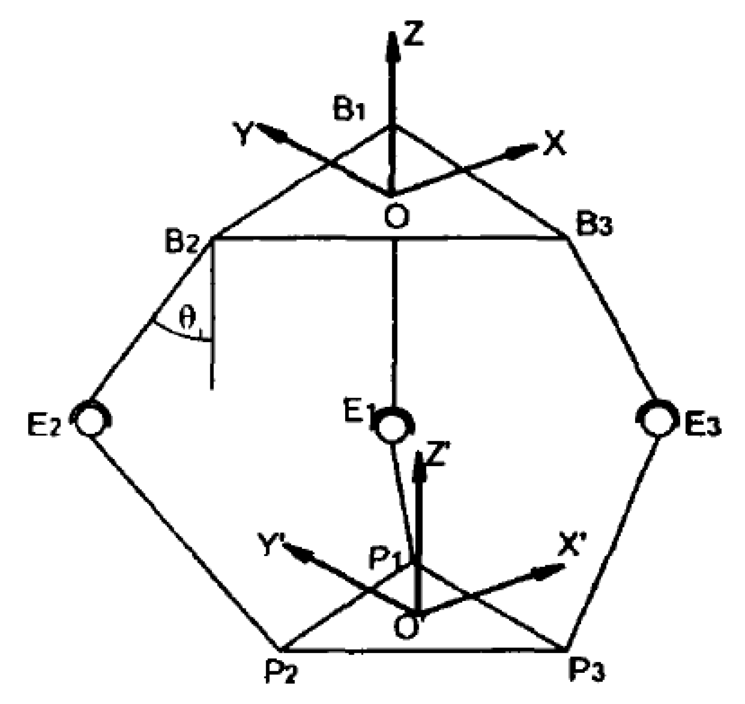
For the basic operating mechanism, the solution for inverse kinematics is used to find the three control variables for the motors after the coordination of the central point of the moving platform related to the static coordinate frame has been decided. It is important to solve the inverse kinematics; thus, the end-effector can move to the desired position. A geometrical representation of the delta robot is illustrated in Figure 3.
The indirect kinematics determines the active joint angles ϕ i based on a given position X p , Y p , Z p of the end effector. By using position vectors in coordination frames, we get
x 2 + [ ( R + L b sin θ 3 - r ) + y ] 2 + ( L b cos θ 3 + z ) 2 = L a 2
After a series of simplifications, we can get a quadratic equation with one unknown,
K i t i 2 + U i t i + V i = 0
where ( i = 1 , 2 , 3 ) ,
t i = tan ( 1 2 θ i )
K i U i V i = L a 2 L b 2 x 2 y 2 z 2 R r 2 + R r 3 x + y L b + 2 z 2 2 R r 3 x y L a 2 L b 2 x 2 y 2 z 2 R r 2 + R r 3 x + y L b 2 z
K i , U i , V i are known; then,
t i = U i ± U i 2 4 K i V i 2 K i ( i = 1 , 2 , 3 )
During the delta robot operation, after setting the pose of the moving frame, the input angle to each motor can be calculated by
θ i = 2 arctan ( t i )
The inverse kinematics of the delta parallel robot in terms of θ i is displayed in Figure 4. The angle of the driving component can be obtained by the upper form, but there may be a combination of eight different solutions, which does not exist. The uniqueness of the solution must be eliminated by adding certain constraints, and the most suitable solution is obtained. The delta parallel mechanism is only small when the bar is out of the way, and the rod is not easily interfered with. Therefore, the elimination strategy in this paper is that the driving angle of each driving rod is the most medial.

2.3. Verification of Kinematics Solution

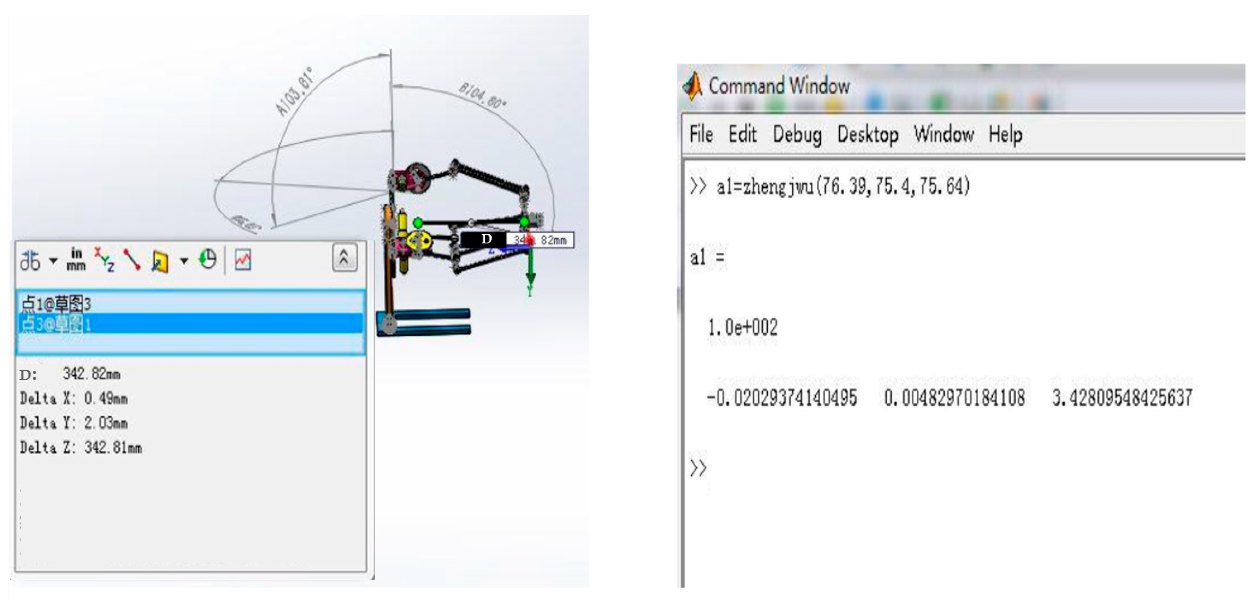
To make the subsequent analysis process more accurate and reliable, the actual three-dimensional model is used to verify the calculation method of the positive and negative solutions. Firstly calibration was performed. The upper arm was put parallel with the base plate to set angles of rotation of the motors. This process was repeated for three upper arms to set three motor angles to achieve calibration at the initial stage. Afterward, the end-effector was set to be positioned at the center, parallel to the base plate, by moving the end-effector relative to the base fixed plate. This process of calibration is necessary to obtain accurate simulation results and hence compare them with real-time values. The verification result of the forward kinematics solution is demonstrated in Figure 5.
The Matlab function input angle is the three-joint angle of the actual reading of SolidWorks 3D, and the correctness of the forward kinematic solution is verified by comparing the input coordinates of these two methods. In order to achieve further accuracy in calculation, a random set of readings was given to both Matlab (R2018a) and SolidWorks (2018), and the calculated error is shown in Table 2. The coordinates in the calculated position are in good agreement with a maximum error of no more than 0.1mm.

3. System Implementation

In this work, the model is designed with one fixed base plate on which motors are mounted and an end-effector that is moveable by linking the upper arm and forearm with the motor’s fixed plate. The model is driven by a Galil controller which controls three motors simultaneously that are mounted in the frame structure of the delta robot at an angle of 120 degrees apart. The attached motors are connected to the Galil controller via connecting wires and communication lines; simultaneously, the Galil motion controller is connected to a PC through the Galil suite software installed on the computer. C++ programming code is developed for the delta robot to drive and control three motors. In the first part of the model, the subject of the delta robot with a three-axis exchange delta parallel mechanism observes translational motion with three degrees of freedom (DOF) along the XYZ Cartesian coordinate system.
In the second part of the modeling, the desired position of the robot is taken by the camera, which will send the position to the robot by the Galil motion controller camera associated with the delta parallel mechanism structure. The mechanism is based on face detection first, after which the program will jump to detecting the eyes of the object. After the successful detection of eyes, the program finds the eye position according to the camera resolution (that will be the frame of reference to calculate XYZ parameters), resulting in the end-effector of the delta robot moving to drive to the detected eyes.
For control technique, this work used position tracking methodology by employing the Galil controller, which records the position of the actuators by encoders. If the target given to the program is reached, the system collects continuous information from the encoder and hence records the path trajectory. The controller will calculate and record the acceleration, deceleration, and speed parameters. The kinematics for the delta robot is developed in C++ code. According to that kinematics, we have to input XYZ to obtain ( θ 1 , θ 2 , θ 3 ) for each motor. The positioning values of the three motors are recorded as per the calculation of the kinematics.

4. Results and Discussion

4.1. Position Tracking of Delta Robot

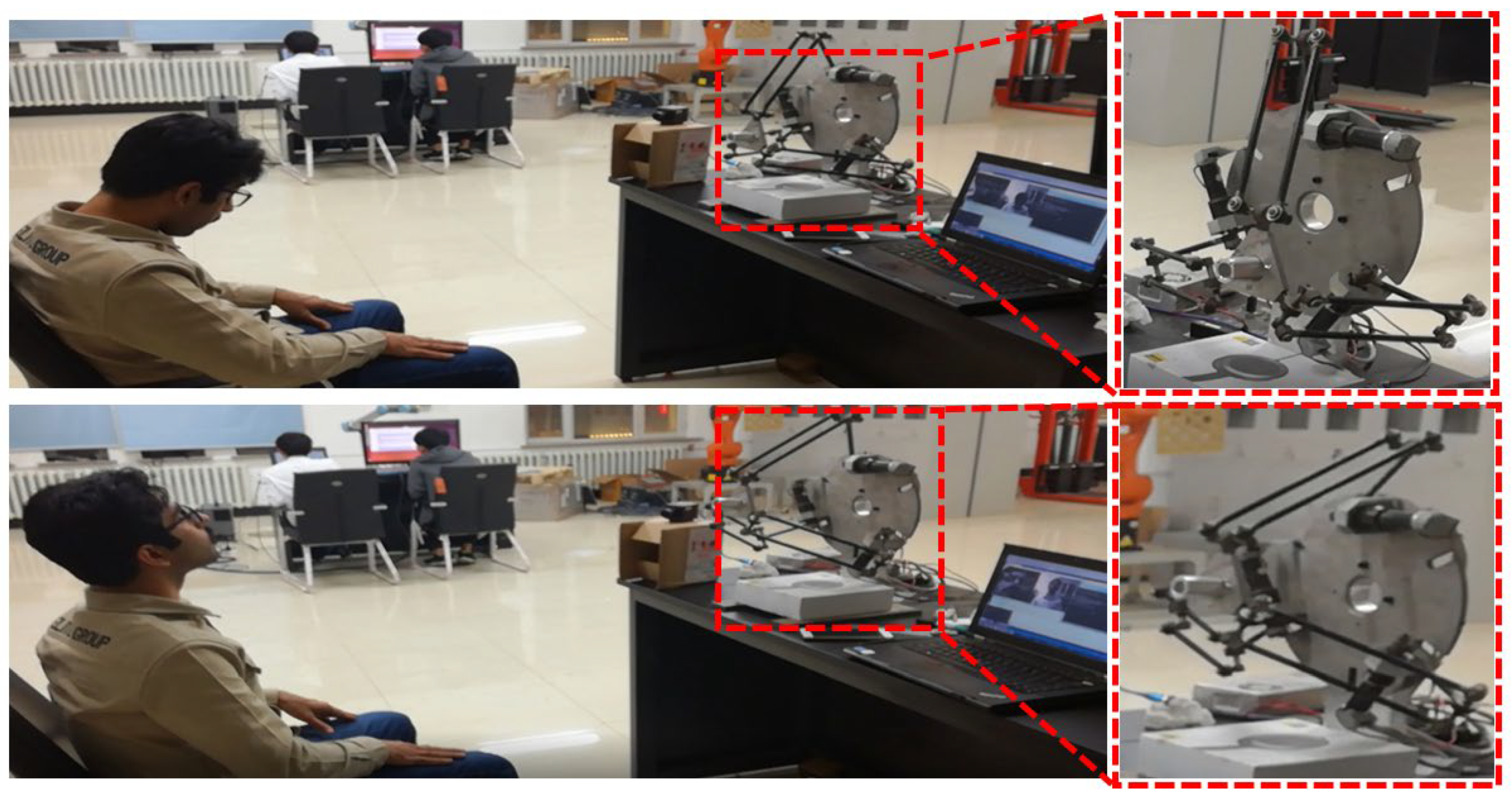
Inverse kinematic analysis-based C++ code is developed using Microsoft Visual Studio 15.5. The position XYZ is given to the controller as an input to obtain ( θ 1 , θ 2 , θ 3 ) as output. Figure 6 demonstrates the motion of the end-effector of the delta robot, which is the angular output of the Galil motion controller; however, the positional input for the controller is given by the camera.

4.2. Eye Tracking

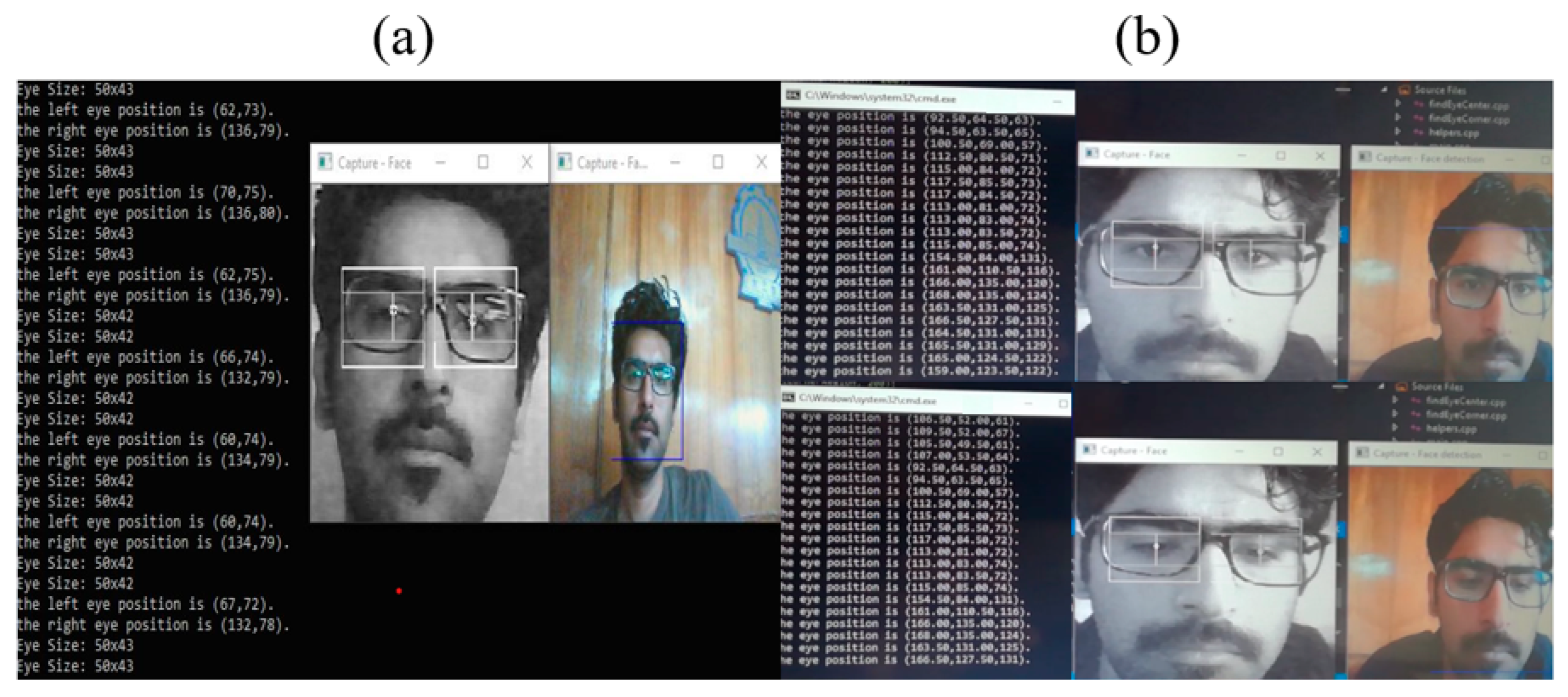
For this work, eyes are taken as a target for object detection using image processing. The code uses the Haar cascade classifier technique for eye detection. In this technique, firstly an image frame is taken by the camera and a classifier is applied to it for face detection and then eye detection. If the result is true in both cases, then the position of eyes is measured and sent to the Galil motion controller as an input to the kinematic algorithm, resulting in the movement of the end-effector of the robot to the detected eye position. But if the result is false or the eyes go out of the frame, the Haar cascade classifier receives a false result and the image window will pause until the eyes come into the range. The output in 2D position before implementing image processing on the controller and delta robot is demonstrated in Figure 7a. In Figure 7b, we validate eye tracking after implementing the image processing-based technique, where the detailed face detection, eye detection and tracking process can be observed. As shown in the figure, the object detection using a camera features real-time tracking of eyes for the delta robot. By using a camera, the relative position of the eyes is recorded and sent to the Galil motion controller, which saves the recorded values sent by the encoder of each motor.

4.3. Experimental Validation

The position taken by the camera is an input to the delta robot; this position is encoded in terms of XYZ and decoded in terms of ( θ 1 , θ 2 , θ 3 ) . For verification, this angular information of each motor is recorded by the encoder to the motion controller, and then the same data is analyzed in MATLAB to observe the real-time curve of the XYZ position simultaneously. The real-time position tracking of the delta robot along the X, Y and Z axes is verified in Figure 8.

4.4. Dual Operating Characteristics

This model is designed to be operated in two modes, i.e., active and passive mode. In active mode, position tracking of the eyes is automatically performed by the camera. However, the passive mode is especially used in the design parameters of the model: if tracking is not achieved by a camera, then the passive mode can be used to operate the delta robot manually. Manual operation of the delta robot means tracking the delta robot by giving the position to the end-effector with a keyboard. In the medical domain, higher accuracy and precision are required to use a machine on a patient, so herein two different interfaces for control are used; i.e., one is by the use of a camera through which real-time eye tracking can be achieved, and another is by the use of a keyboard to input the position of the end-effector of the delta robot manually.

5. Conclusions

This paper presents a delta robot for real-time continuous eye tracking by using the Galil motion controller, which can be used to facilitate ophthalmologists during the eye-checking process. The delta robot consists of three actuators for moving its end effector and is designed to move along X, Y, and Z coordinates, from position 1 to position 2 in the Cartesian coordinate system. The C++ vision servo program is designed to carry out object detection through image processing using Haar classifiers. Finally, the visual servo-based motion of the delta robot’s end-effector is accomplished by combining motion controller movements and image processing into a single system. Experiments are conducted to assess the effectiveness of the developed model in terms of image processing. Furthermore, the kinematic analysis, which is essential for acquiring three-dimensional data on the delta robot, is validated in this paper. The model is developed to have dual operating modes; one is active mode and another is passive mode. In active mode, position tracking is performed by a camera, i.e., automatic tracking; however in passive mode, position tracking is achieved by a keyboard, i.e., manual tracking. This model can be implemented to facilitate eye specialists by replacing manual eye-checking equipment with automatic, unattended, computerized eye checkups by the use of an auto-refractometer.

Author Contributions

Conceptualization, methodology, writing—original draft preparation, M.M.M.; software, validation, review and editing, A.H.; review and editing, A.M. (Abdulrhman Mohammed) and A.M. (Ali Manthar); supervision, S.L. and W.L. All authors have read and agreed to the published version of the manuscript.

Funding

This research received no external funding.

Institutional Review Board Statement

In this research, the instrument only captured the body postures of the participants through cameras, had no contact with them, and did not cause any form of harm to their bodies. Therefore, this research has applied for exemption from ethical review by the ethics committee.

Informed Consent Statement

Informed consent was obtained from all subjects involved in the study.

Data Availability Statement

The original contributions presented in the study are included in the article, further inquiries can be directed to the corresponding author.

Conflicts of Interest

The authors declare no conflicts of interest.

References

  1. Wu, H. Research on Control System of Delta Robot Based on Visual Tracking Technology. J. Phys. Conf. Ser. 2021, 1883, 012110. [Google Scholar] [CrossRef]
  2. Li, M.; Milojevic, A.; Handroos, H. Robotics in Manufacturing—The Past and the Present. In Technical, Economic and Societal Effects of Manufacturing 4.0; Palgrave Macmillan Cham: London, UK, 2020; pp. 85–95. ISBN 978-3-030-46102-7. [Google Scholar]
  3. Brinker, J.; Funk, N.; Ingenlath, P.; Takeda, Y.; Corves, B. Comparative Study of Serial-Parallel Delta Robots with Full Orientation Capabilities. IEEE Robot. Autom. Lett. 2017, 2, 920–926. [Google Scholar] [CrossRef]
  4. McClintock, H.; Temel, F.Z.; Doshi, N.; Koh, J.-S.; Wood, R.J. The MilliDelta: A High-Bandwidth, High-Precision, Millimeter-Scale Delta Robot. Sci. Robot. 2018, 3, eaar3018. [Google Scholar] [CrossRef] [PubMed]
  5. Bulej, V.; Stanček, J.; Kuric, I. Vision Guided Parallel Robot and Its Application for Automated Assembly Task. Adv. Sci. Technol. Res. J. 2018, 12, 150–157. [Google Scholar] [CrossRef] [PubMed]
  6. Correa, J.E.; Toombs, J.; Toombs, N.; Ferreira, P.M. Laminated Micro-Machine: Design and Fabrication of a Flexure-Based Delta Robot. J. Manuf. Process. 2016, 24, 370–375. [Google Scholar] [CrossRef]
  7. Rehman, S.U.; Raza, M.; Khan, A. Delta 3D Printer: Metal Printing. J. Electr. Eng. Electron. Control. Comput. Sci. 2019, 5, 19–24. [Google Scholar]
  8. Mitsantisuk, C.; Stapornchaisit, S.; Niramitvasu, N.; Ohishi, K. Force Sensorless Control with 3D Workspace Analysis for Haptic Devices Based on Delta Robot. In Proceedings of the IECON 2015—41st Annual Conference of the IEEE Industrial Electronics Society, Yokohama, Japan, 9–12 November 2015; pp. 1747–1752. [Google Scholar]
  9. Singh, B.; Sellappan, N.; Kumaradhas, P. Evolution of Industrial Robots and Their Applications. Int. J. Emerg. Technol. Adv. Eng. 2008, 3, 763–768. [Google Scholar]
  10. Hoai, P.L.; Cong, V.D.; Hiep, T.T. Design a Low-Cost Delta Robot Arm for Pick and Place Applications Based on Computer Vision. FME Trans. 2023, 51, 99–108. [Google Scholar] [CrossRef]
  11. Kratchman, L.B.; Blachon, G.S.; Withrow, T.J.; Balachandran, R.; Labadie, R.F.; Webster, R.J. Design of a Bone-Attached Parallel Robot for Percutaneous Cochlear Implantation. IEEE Trans. Biomed. Eng. 2011, 58, 2904–2910. [Google Scholar] [CrossRef] [PubMed]
  12. Dan, V.; Stan, S.-D.; Manic, M.; Balan, R. Mechatronic Design, Kinematics Analysis of a 3 DOF Medical Parallel Robot. In Proceedings of the 2010 3rd International Symposium on Resilient Control Systems, Idaho Falls, ID, USA, 10–12 August 2010; pp. 101–106. [Google Scholar]
  13. Bahaghighat, M.; Akbari, L.; Xin, Q. A Machine Learning-Based Approach for Counting Blister Cards Within Drug Packages. IEEE Access 2019, 7, 83785–83796. [Google Scholar] [CrossRef]
  14. Moradi Dalvand, M.; Shirinzadeh, B. Motion Control Analysis of a Parallel Robot Assisted Minimally Invasive Surgery/Microsurgery System (PRAMiSS). Robot. Comput.-Integr. Manuf. 2013, 29, 318–327. [Google Scholar] [CrossRef]
  15. Pisla, D.; Gherman, B.; Vaida, C.; Suciu, M.; Plitea, N. An Active Hybrid Parallel Robot for Minimally Invasive Surgery. Robot. Comput.-Integr. Manuf. 2013, 29, 203–221. [Google Scholar] [CrossRef]
  16. Kuo, C.-H.; Dai, J.S. Kinematics of a Fully-Decoupled Remote Center-of-Motion Parallel Manipulator for Minimally Invasive Surgery. J. Med. Devices 2012, 6, 021008. [Google Scholar] [CrossRef]
  17. Khalifa, A.; Fanni, M.; Mohamed, A.M.; Miyashita, T. Development of a New 3-DOF Parallel Manipulator for Minimally Invasive Surgery. Int. J. Med. Robot. Comput. Assist. Surg. 2018, 14, e1901. [Google Scholar] [CrossRef] [PubMed]
  18. Sahu, U.K.; Mishra, A.; Sahu, B.; Pradhan, P.P.; Patra, D.; Subudhi, B. Vision-Based Tip Position Control of a Single-Link Robot Manipulator. In Proceedings of the International Conference on Sustainable Computing in Science, Technology and Management (SUSCOM), Jaipur, India, 26–28 February 2019. [Google Scholar] [CrossRef]
  19. Fang, Y.; Liu, X.; Zhang, X. Adaptive Active Visual Servoing of Nonholonomic Mobile Robots. IEEE Trans. Ind. Electron. 2012, 59, 486–497. [Google Scholar] [CrossRef]
  20. Ficocelli, M.; Janabi-Sharifi, F. Adaptive Filtering for Pose Estimation in Visual Servoing. In Proceedings of the 2001 IEEE/RSJ International Conference on Intelligent Robots and Systems. Expanding the Societal Role of Robotics in the Next Millennium (Cat. No.01CH37180), Maui, HI, USA, 29 October–3 November 2001; Volume 1, pp. 19–24. [Google Scholar]
  21. Gridseth, M.; Ramirez, O.; Quintero, C.P.; Jagersand, M. ViTa: Visual Task Specification Interface for Manipulation with Uncalibrated Visual Servoing. In Proceedings of the 2016 IEEE International Conference on Robotics and Automation (ICRA), Stockholm, Sweden, 16–21 May 2016; pp. 3434–3440. [Google Scholar]
  22. Rouhollahi, A.; Azmoun, M.; Masouleh, M.T. Experimental Study on the Visual Servoing of a 4-DOF Parallel Robot for Pick-and-Place Purpose. In Proceedings of the 2018 6th Iranian Joint Congress on Fuzzy and Intelligent Systems (CFIS), Kerman, Iran, 28 February–2 March 2018; pp. 27–30. [Google Scholar]
  23. Hu, C.-Y.; Chen, C.-R.; Tseng, C.-H.; Yudha, A.P.; Kuo, C.-H. Visual Servoing Spanner Picking and Placement with a SCARA Manipulator. In Proceedings of the 2016 IEEE International Conference on Industrial Technology (ICIT), Taipei, Taiwan, 14–17 March 2016; pp. 1632–1637. [Google Scholar]
  24. Asadi, K.; Jain, R.; Qin, Z.; Sun, M.; Noghabaei, M.; Cole, J.; Han, K.; Lobaton, E. Vision-Based Obstacle Removal System for Autonomous Ground Vehicles Using a Robotic Arm. arXiv 2019, arXiv:1901.08180. [Google Scholar] [CrossRef]
  25. Hafez, H.; Marey, M.; Tolbah, F.; Abdelhameed, M. Survey of Visual Servoing Control Schemes for Mobile Robot Navigation. Sci. J. Oct. 6 Univ. 2017, 3, 41–50. [Google Scholar] [CrossRef]
  26. Shi, H.; Chen, J.; Pan, W.; Hwang, K.-S.; Cho, Y.-Y. Collision Avoidance for Redundant Robots in Position-Based Visual Servoing. IEEE Syst. J. 2019, 13, 3479–3489. [Google Scholar] [CrossRef]
  27. López-Nicolás, G.; Özgür, E.; Mezouar, Y. Parking Objects by Pushing Using Uncalibrated Visual Servoing. Auton. Robot. 2019, 43, 1063–1078. [Google Scholar] [CrossRef]
  28. Olsson, A. Modeling and Control of a Delta-3 Robot. Master’s Thesis, Lund University, Lund, Sweden, 2009. [Google Scholar]
  29. Prempraneerach, P. Delta Parallel Robot Workspace and Dynamic Trajectory Tracking of Delta Parallel Robot. In Proceedings of the 2014 International Computer Science and Engineering Conference (ICSEC), Khon Kaen, Thailand, 30 July–1 August 2014; pp. 469–474. [Google Scholar]
Figure 1. Delta parallel robot with its parts: (a) front view; (b) back view.
Applsci 15 12521 g001
Figure 2. Forward kinematics transforms positions ( θ 1 , θ 2 , θ 3 ) into XYZ.
Applsci 15 12521 g002
Figure 3. Geometrical representation of delta robot.
Applsci 15 12521 g003
Figure 4. Inverse kinematics transforms XYZ into angle positions ( θ 1 , θ 2 , θ 3 ) .
Applsci 15 12521 g004
Figure 5. Forward kinematic solution verification.
Applsci 15 12521 g005
Figure 6. Experimental validation of the visual servo-based eye tracking of the delta robot.
Applsci 15 12521 g006
Figure 7. Continuous eye tracking observation: (a) before using image processing; (b) after image processing.
Applsci 15 12521 g007
Figure 8. Real-time position tracking of delta robot along (a) X-axis, (b) Y-axis, and (c) Z-axis.
Applsci 15 12521 g008
Table 1. Dimensions of delta parallel structure.
Translational WorkspaceRotation RangeLinear Motion SpeedAngular Motion SpeedFeedback ForceTorque
120 × 100 mm±608 mm/s10 r/min20 N0.3 N·m
Table 2. SolidWorks and Matlab software computing results.
Serial Number (sr)ExampleSolidWorks 3D (mm)Matlab (mm)Error
θ 1 θ 2 θ 3 XYZXYZΔ
1−30−30−3000124.1400124.140
27.9908.442.433.31151.412.443.31151.410.01
359.9874.1623.6−19−103.8277.6−18.97−103.8277.630.121
419.1−14−12−43.572.56160.74−43.582.57160.740.014
5−6.223.866.633.54−24.6183.4233.54−24.59183.420.01
667.0361.9118.8−62−82.25270.4−62.09−82.24270.420.017
73.33−0.6341.130.9264.38191.8230.9364.39191.820.014
824.8446.4443.244.71−6.89261.3944.71−6.9261.390.01
976.3975.475.6−2.30.49342.81−2.030.48342.810.01
1024.1744.8647.3495.23262.149.025.24262.140.014
1122.6163.61843.4−90.223543.38−90.2235.030.01
1237.0373.6125.636.1−102.5259.536.1−102.5259.530.01
1353.8226.4749.8−3745.79271.8−36.9545.8271.80.014
1427.5361.6568.38716.46284.687.0316.45284.630.017
Disclaimer/Publisher’s Note: The statements, opinions and data contained in all publications are solely those of the individual author(s) and contributor(s) and not of MDPI and/or the editor(s). MDPI and/or the editor(s) disclaim responsibility for any injury to people or property resulting from any ideas, methods, instructions or products referred to in the content.