Review

A Review on Piezoelectric Ultrasonic and Peristaltic Methods for Precision Motion and Measurement

Beijing Engineering Research Center of Precision Measurement Technology and Instruments, Beijing University of Technology, Beijing 100124, China
*
Author to whom correspondence should be addressed.
Appl. Sci. 2025, 15(23), 12510; https://doi.org/10.3390/app152312510
Submission received: 22 September 2025 / Revised: 10 November 2025 / Accepted: 10 November 2025 / Published: 25 November 2025

Abstract

Compared with electromagnetic motors, piezoelectric motors have the advantages of high torque, self-locking, and resistance to electromagnetic interference. According to the difference in working principle, piezoelectric motors are divided into ultrasonic motors and peristaltic motors. Currently, a kind of diamond-shaped oscillator ultrasonic motor for use in micro probes and a kind of anti-clamp peristaltic motor for use in spacecraft mass adjustment are being systematically developed by our research team. In order to summarize the experience and lessons learned, we conducted research on the principles, structures, and applications of existing piezoelectric drive motors, analyzed the advantages and problems of existing technologies, and developed a plan and expected indicators for completing this project. Finally, a report on the performance characteristics of different types of piezoelectric drive motors in terms of stroke range, speed, accuracy, and load capacity was summarized for reference.

1. Introduction

Piezoelectric motors feature flexible structural design, compact size, no magnetic interference, high displacement resolution, and large travel range. They hold great application potential in fields requiring precise positioning, such as aerospace, precision optics, and precision machining [1,2,3,4,5,6]. These motors utilize the inverse piezoelectric effect to convert electrical energy into mechanical energy, which is then transformed into kinetic energy through a series of specialized mechanisms [7].
Based on their driving methods and operating principles, piezoelectric motors can be categorized into ultrasonic motors and piezoelectric peristaltic motors, with the primary differences lying in the method and structure used for kinetic energy conversion [8,9,10,11]. The basic governing equations for piezoelectric motor performance can be expressed as follows:
T = μ F r
P = T × ω
η = P o u t P i n
T is the output torque, F is the tangential frictional driving force, r is the effective radius of the contact surface, μ is the friction coefficient between the stator and rotor (or slider), P is the mechanical power output, ω is the angular velocity, V and I are the input voltage and current, and η represents the overall energy conversion efficiency.
The step size of an ultrasonic motor under one pulse is very small, so it needs high frequency excitation [12,13]. Therefore, the speed of the ultrasonic motor is usually faster, but the accuracy of repeated positioning is poor [14,15,16]. The increase in the step size of the peristaltic motor is realized by the accumulation of multiple ceramic stacks, so the thickness and volume are larger. Therefore, the repetitive positioning accuracy of the peristaltic motor is better, but the speed is lower [17,18,19,20,21].
This review adopted a structured approach to ensure completeness and objectivity. Literature searches were performed in Web of Science, Scopus, IEEE Xplore, and Google Scholar using the keywords “piezoelectric motor,” “ultrasonic motor,” and “peristaltic motor.” The search covered 1995–2025. Only peer-reviewed journal papers and patents providing quantitative analysis were included. Data were classified according to motor type, structure, and application field, forming the basis for comparative discussion.

2. Ultrasonic Motor

The principle of ultrasonic motors is as follows: by applying a pre-tightening force to the stator and rotor, which form a kinematic pair, the vibration energy generated from electrical energy is directly converted into the driving force of the rotor, thereby enabling high-efficiency continuous rotational or linear motion [22,23,24,25,26]. Ultrasonic motors inherently offer advantages such as high torque, fast dynamic response, and immunity to electromagnetic interference [27,28,29,30,31]. This is because their operating mechanism is fundamentally different from that of traditional motors, which obtain speed and torque through electromagnetic effects. Instead, ultrasonic motors apply an alternating voltage at ultrasonic frequencies to piezoelectric ceramics, and through the inverse piezoelectric effect, electrical energy is converted into kinetic and mechanical energy. The emergence of ultrasonic motors has resolved the conflict between small size and high torque in the aerospace field (Figure 1a [32]), while their self-locking capability upon power-off makes them highly suitable for high-precision positioning in advanced manufacturing (Figure 1b [33]). The performance of the friction materials in ultrasonic motors differs significantly between vacuum environments and ground test conditions, which in turn leads to a decline in the motor’s performance. Additionally, Ultrasonic motors enable fast speeds for pointing mechanisms and solar panel deployment. However, they have the disadvantage of low positioning accuracy. As a result, ultrasonic motor technology holds broad application prospects.
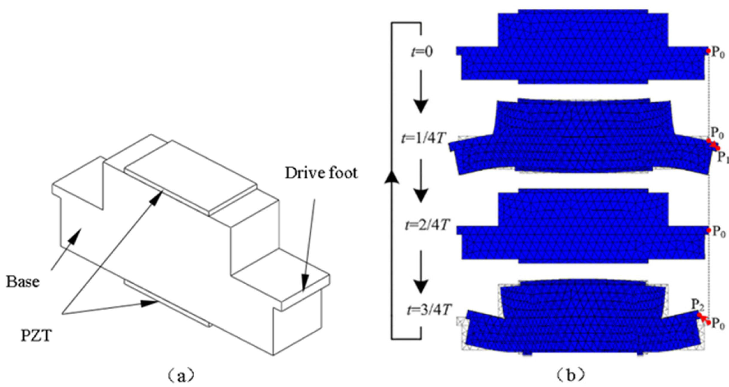
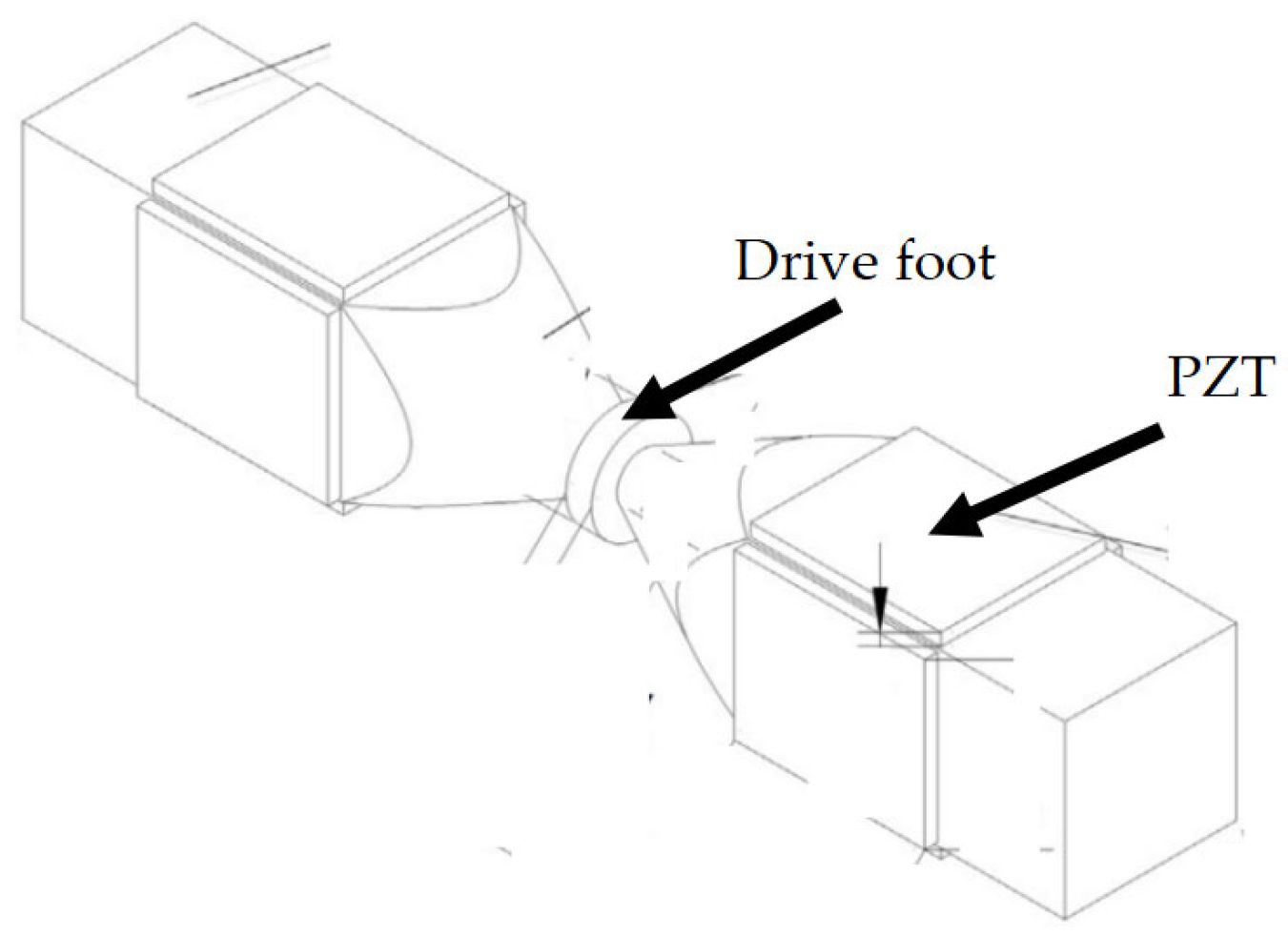
Wang et al. [34] developed a standing-wave ultrasonic motor with asymmetric structure. By exciting the piezoelectric elements attached to a metal substrate (Figure 2a), the driving foot generates periodic vibrations (Figure 2b). Experimental results indicate that when the pre-tightening force is 30 N and the excitation voltage is 150 V, the motor achieves a maximum no-load speed of 0.12 m/s and a maximum thrust of 2.8 N.
Standing-wave ultrasonic motors commonly suffer from end wear issues, which can lead to component fracture, aging, and a shortened operational lifespan.
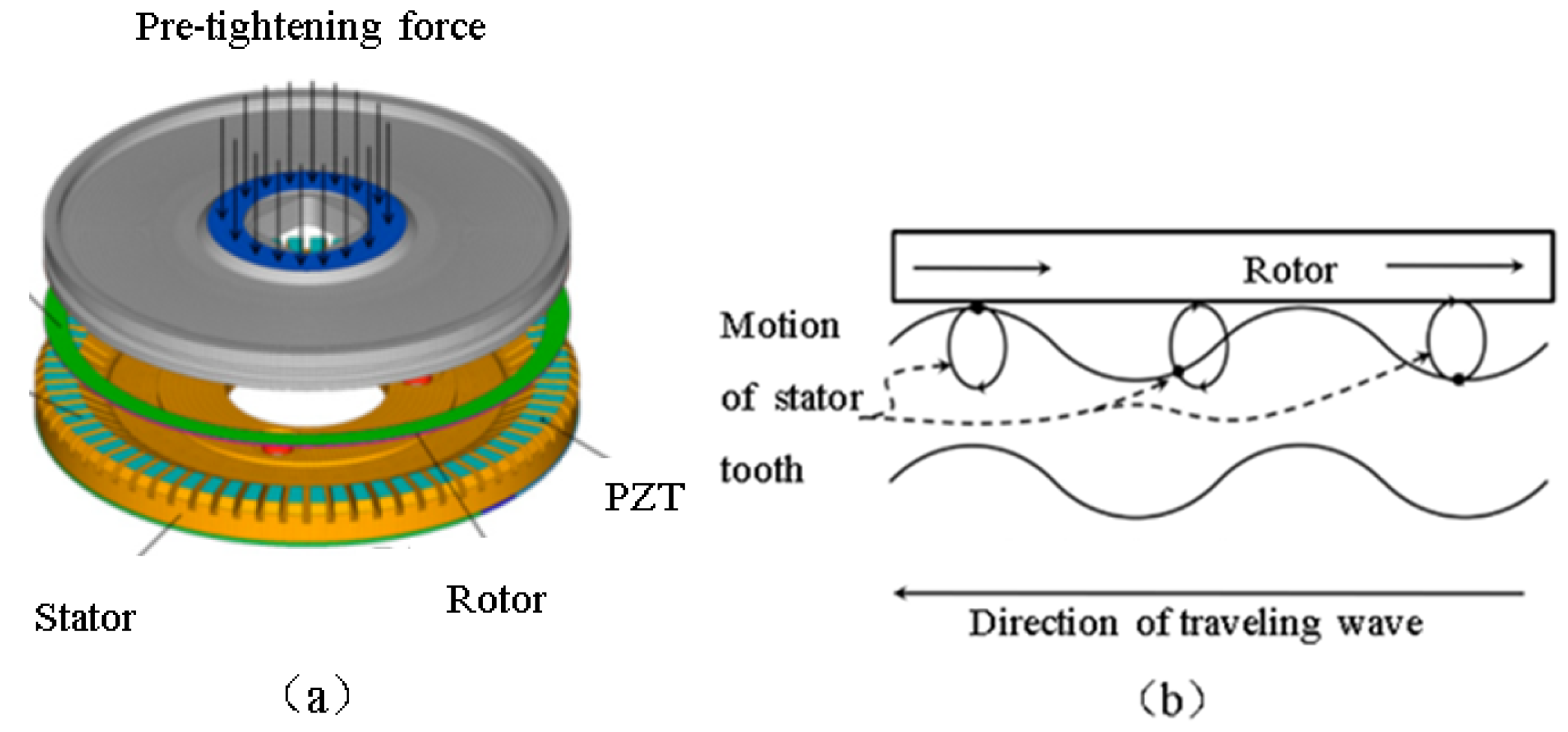
Yang et al. [35] developed an annular traveling-wave ultrasonic motor, consisting of a ring-shaped rotor and a stator bonded with piezoelectric ceramics, as shown in Figure 3a [35]. When an alternating voltage is applied to the piezoelectric ceramics, the stator generates a bending traveling wave along the circumferential direction. Energy conversion and transfer occur through friction between the stator and rotor, causing the rotor to undergo continuous rotation, as illustrated in Figure 3b.
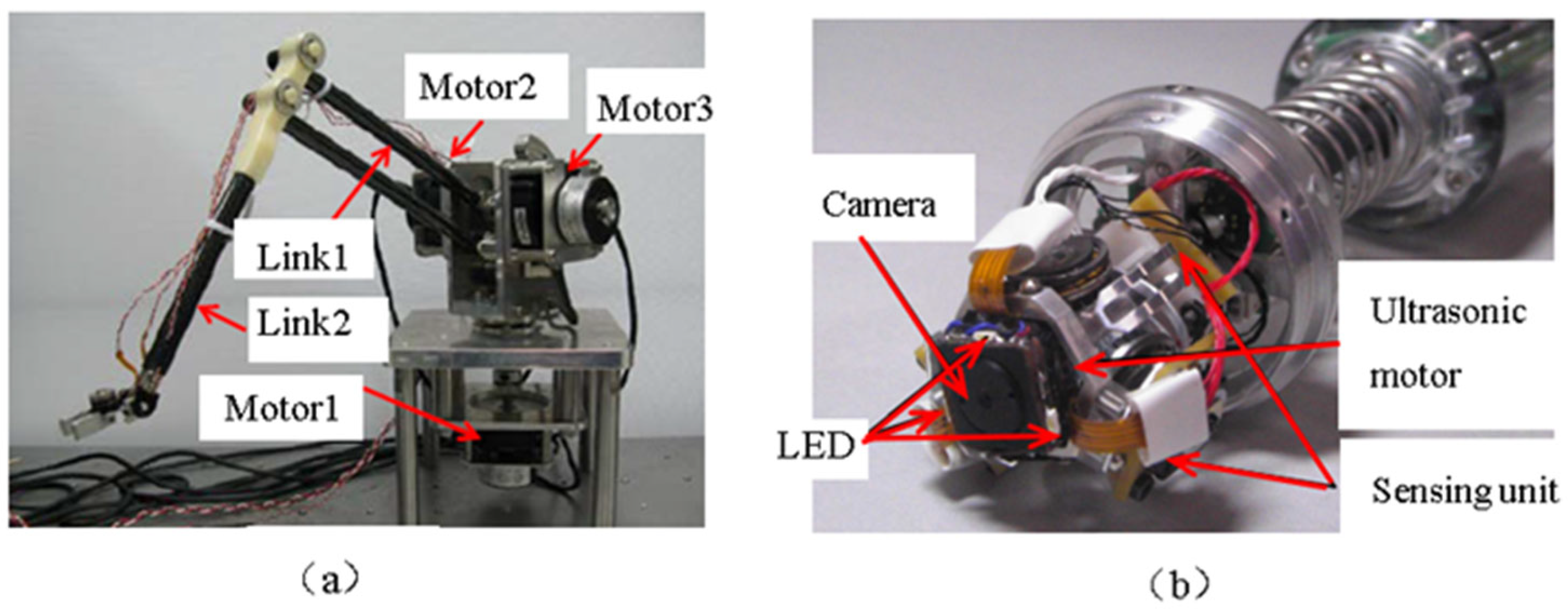
Compared to standing-wave ultrasonic motors, traveling-wave ultrasonic motors exhibit higher energy conversion efficiency, reduced wear, and significantly improved lifespan. They have been widely applied in fields such as robotic arms (Figure 4a [36]) and pipeline vision inspection instruments (Figure 4b [37]).
To further enhance efficiency, increase torque, and reduce size, a new principle of composite-mode ultrasonic motors has been proposed in recent years. The principle involves generating two perpendicular simple harmonic vibrations of the same frequency, with a phase difference of one-quarter cycle, which combine at the driving foot to produce an elliptical motion, thereby driving the rotor [38]. By combining different vibration modes, this type of motor achieves higher efficiency, greater output torque, and more complex motion control. The four common types of composite-mode ultrasonic motors are longitudinal-longitudinal, longitudinal-bending, longitudinal-torsional, and bending–bending composite-mode ultrasonic motors.
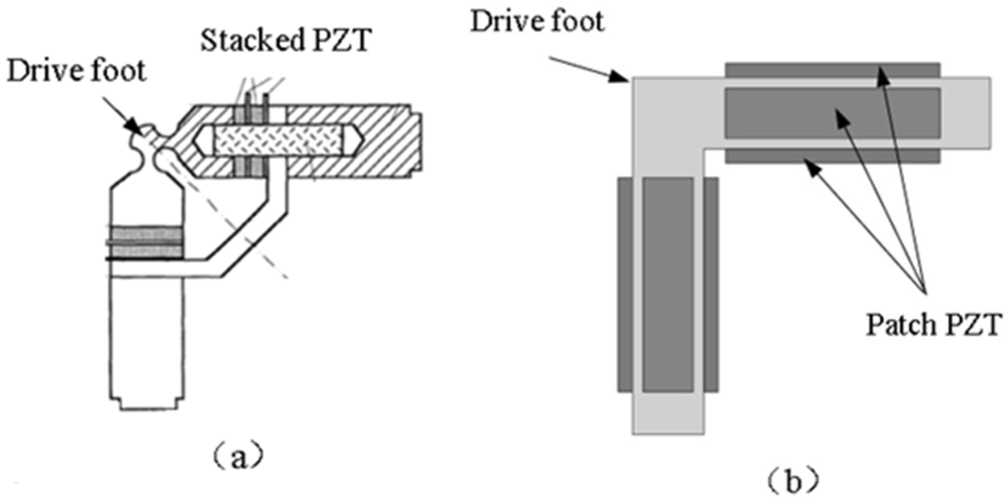
Kurosawa et al. [39] developed a V-shaped longitudinal-longitudinal composite-mode ultrasonic motor. In this design, two piezoelectric stacked stators are arranged orthogonally, with their connection points designed as flexible hinge structures. By utilizing the first-order longitudinal vibration mode composite, the amplitude and torque are amplified, generating an elliptical motion at the driving foot located at the flexible hinge (Figure 5a). Experimental results show that the motor achieves a maximum no-load speed of 3.5 m/s and a maximum output force of 51 N, whereas conventional single-mode ultrasonic motors typically reach a maximum speed of 1 m/s and a maximum output force of 5 N—demonstrating significant performance
Jeong et al. [40] also developed a V-shaped metal plate vibrator. In this design, four ceramic plates are attached to the four sides of the vibrator. By applying two electric fields with a 90° phase difference to the ceramics, the longitudinal vibration mode is excited at the driving foot, generating an elliptical motion (Figure 5b). Experimental results indicate that this motor achieves a maximum no-load speed of 7 m/s and a maximum output force of 75 N. Compared with piezoelectric stacked ultrasonic motors [41], placing piezoelectric ceramics on all four sides more effectively excites longitudinal vibration.
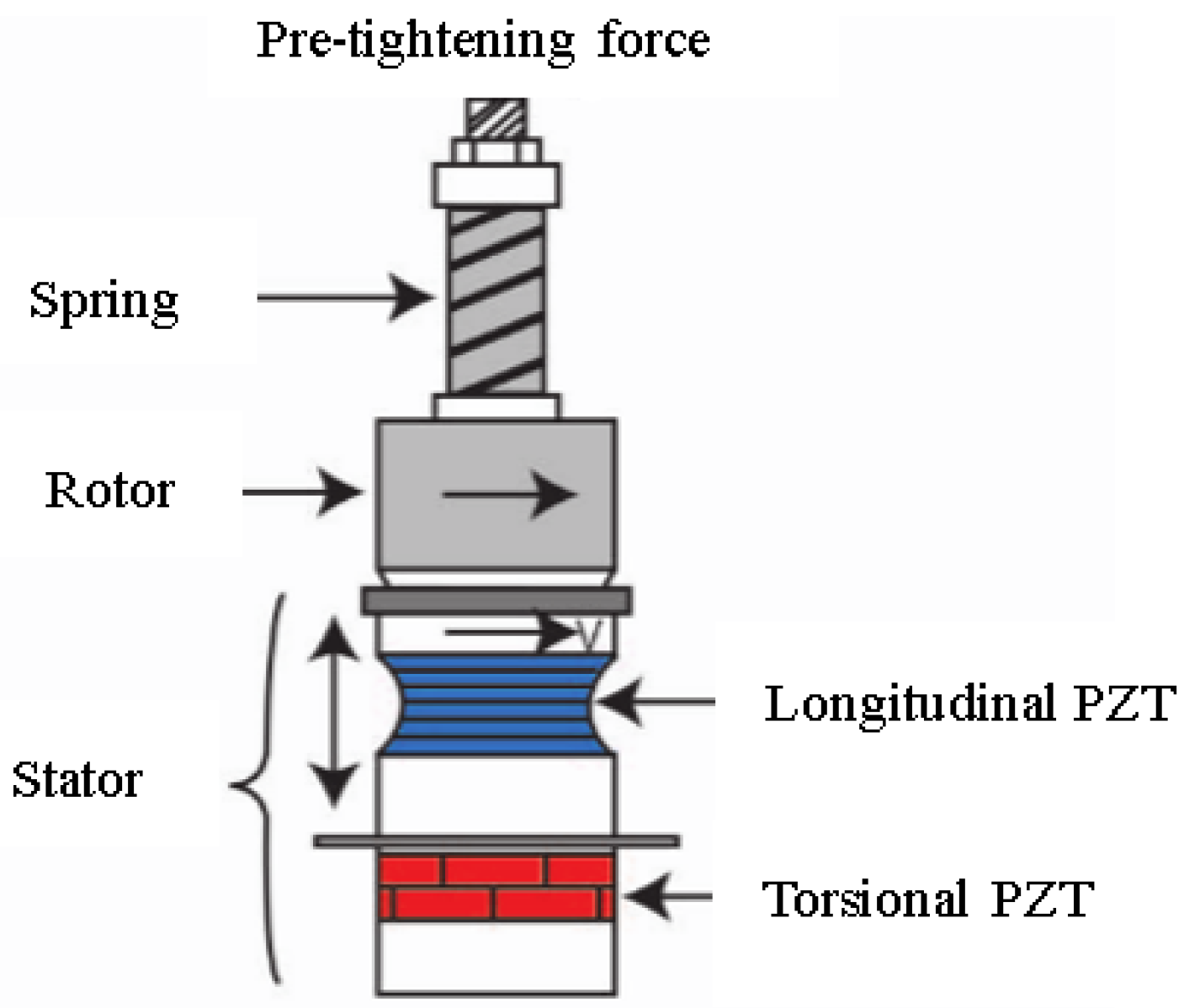
Wei et al. [42] developed a cylindrical longitudinal-torsional composite-mode ultrasonic motor. In this design, a spring applies a pre-tightening force to the rotor and stator pair. By exciting the longitudinal and torsional piezoelectric ceramics, the stator generates periodic vibrations. When the torsional piezoelectric ceramic drives in the forward direction, the longitudinal vibration compresses the spring, increasing the pre-tightening force and causing the rotor to rotate forward. Conversely, when the torsional vibration reverses, the longitudinal piezoelectric ceramic retracts, reducing the pre-tightening force and preventing reverse rotation of the rotor (Figure 6).
Yan et al. [43] developed a symmetric composite-mode ultrasonic motor, as shown in Figure 7. Two ultrasonic transducers are placed opposite each other, with the connection point serving as the driving foot. Piezoelectric ceramics are mounted on both transducers, and when voltage is applied, two mutually orthogonal bending vibrations are generated. These vibrations combine at the driving foot to produce an elliptical motion. Experimental results show that the symmetric structure effectively prevents undesired lateral motion caused by bending vibrations and avoids modal degeneration. Additionally, the motor’s output speed exhibits an approximately linear relationship with the driving frequency and voltage amplitude, demonstrating excellent controllability.
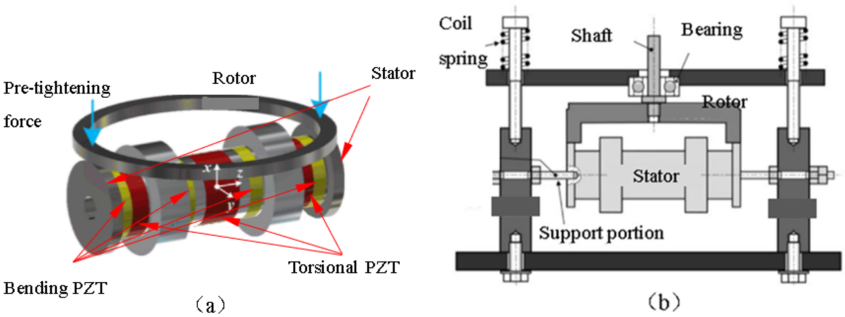
Wu et al. [44] developed a cylindrical bending–torsional composite-mode ultrasonic motor, as shown in Figure 8a. In this design, a helical spring applies a pre-tightening force to an annular rotor, while torsional and bending piezoelectric ceramics are symmetrically arranged in a sandwich configuration (Figure 8b). Four bending piezoelectric ceramics sandwich three torsional piezoelectric ceramics, enabling resonant frequency merging and maximum amplitude output without modal degeneration.
During forward driving, the bending vibration compresses the spring, increasing the pre-tightening force, while the torsional piezoelectric ceramics generate the driving force, causing the rotor to rotate forward. When torsional vibration reverses, the stator bends downward, reducing the pre-tightening force and ensuring that the rotor does not undergo reverse motion. Experimental results show that when operating at 21.64 kHz, the motor achieves a maximum torque of 10.1 N·m and a maximum output power of 38.1 W.
Magnetic resonance imaging (MRI) equipment is susceptible to electromagnetic interference during operation, making traditional electromagnetic motors unsuitable for driving such systems [45]. In contrast, ultrasonic motors do not interfere with the imaging process, allowing for clear image acquisition and thereby improving diagnostic accuracy [46].
Electromechanical systems often face an inherent conflict between small size and high torque, which is particularly evident in aerospace applications. For example, both the Chang’e-3 and Chang’e-4 lunar rovers are driven by ultrasonic motors, addressing the problem of insufficient output torque in miniaturized conventional motors. As shown in the ultrasonic motor used for propulsion weighs only one-tenth of a traditional motor but features a start-stop response time of just 0.1–1 ms [47,48].
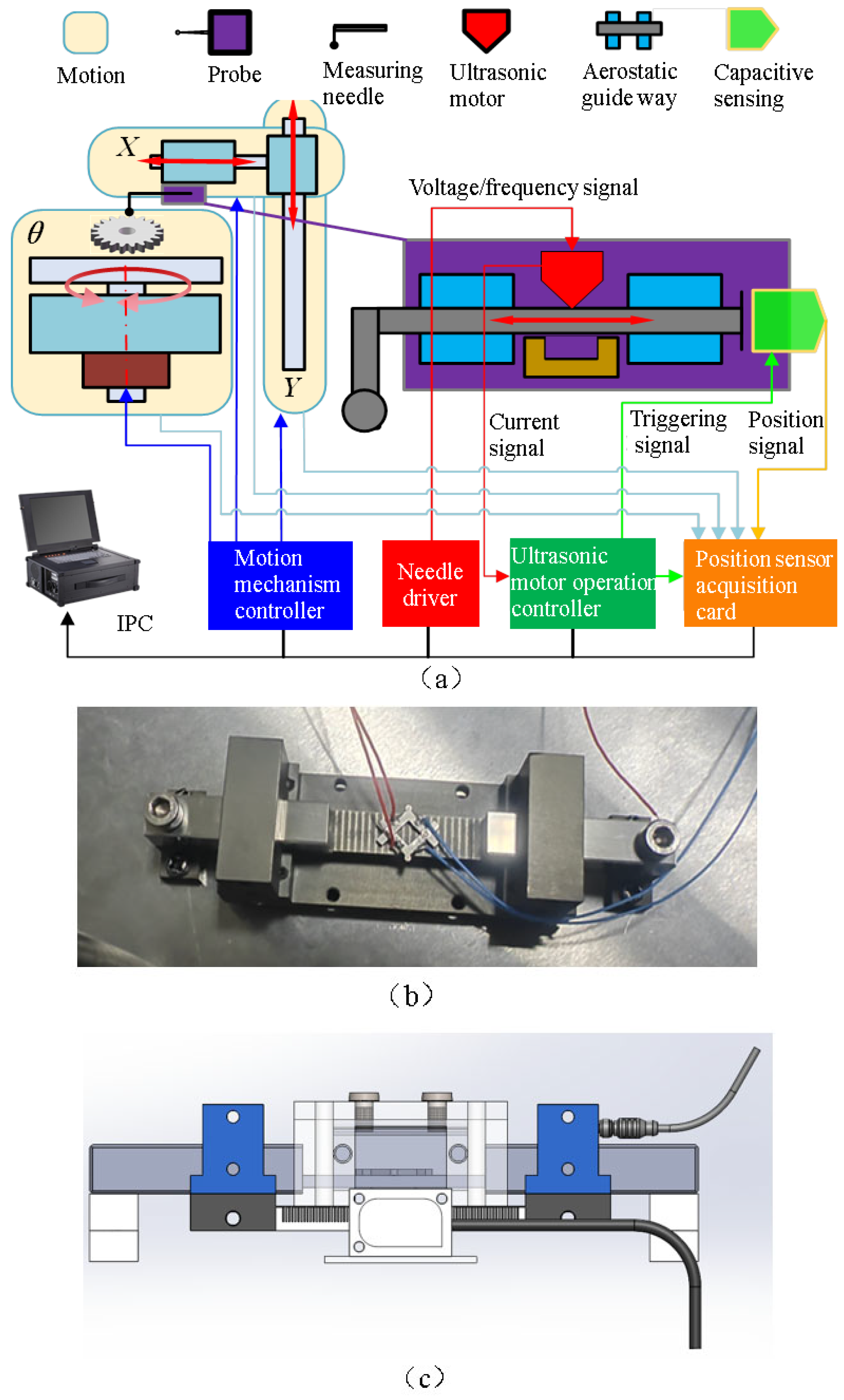
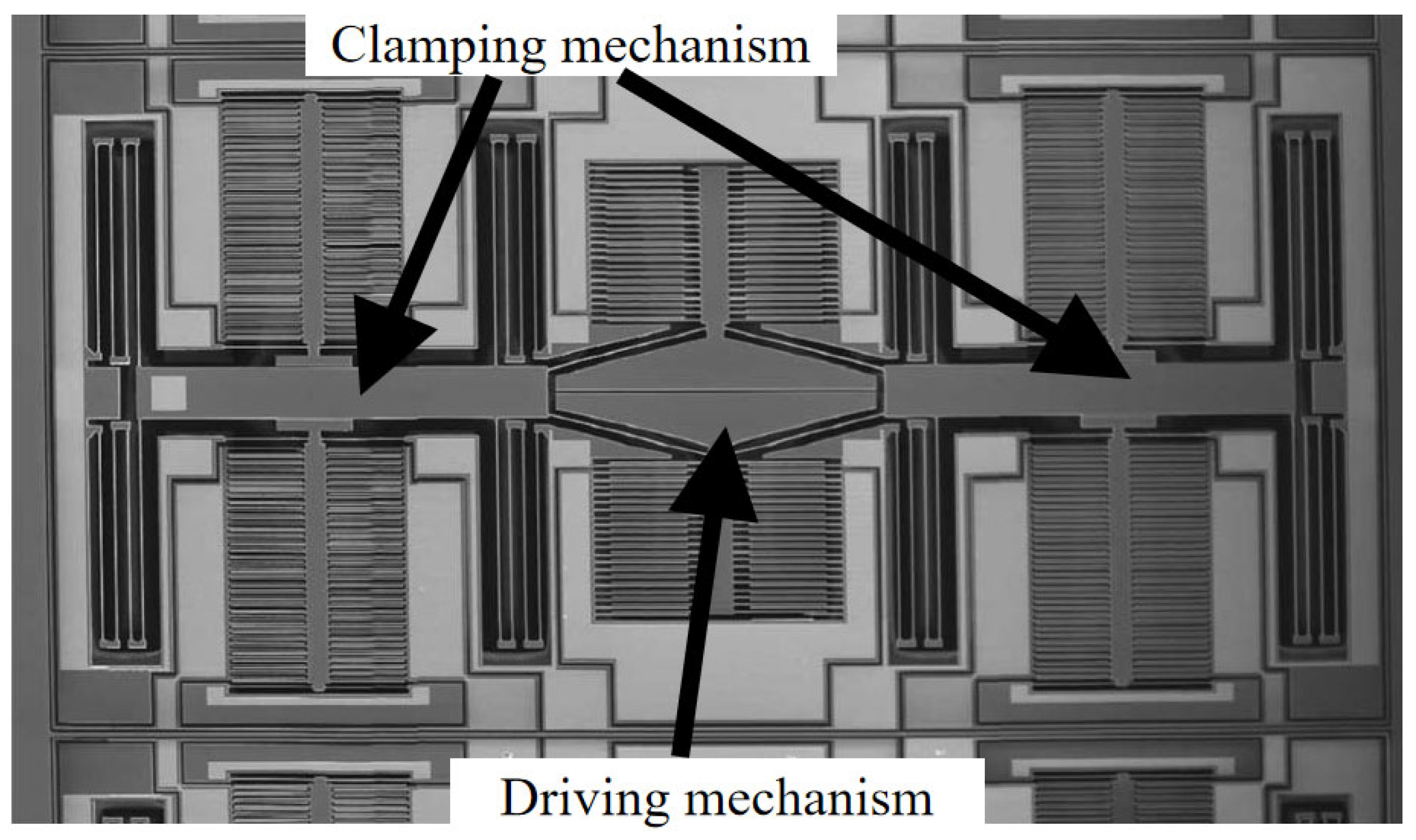
Our research team has proposed a high-precision macro-micro measurement method based on ultrasonic drive, as shown in Figure 9a. The principle involves integrating an ultrasonic motor with an aerostatic guide way inside the probe. Once the motion mechanism positions the probe near the measured gear, the ultrasonic motor drives the probe tip to generate micro-displacement, enhancing measurement sensitivity while reducing contact measurement force. Therefore, the development of a small ultrasonic motor for this project is very necessary.
As shown in Figure 9b,c, piezoelectric ceramics are attached to the four variable outer sides of a diamond-shaped stator [38] and are driven by sinusoidal voltages with a 90° phase difference. The elliptical motion generated by the diamond-shaped stator drives the outer pre-tightening hinge, which is mounted on a base and moves linearly along the aerostatic guide way. Research findings indicate that designing the motor stator in a diamond shape with a tail fin structure can provide sufficient torque to drive micron-scale motion along the aerostatic guide way within a confined space.

3. Peristaltic Motor

The principle of a piezoelectric peristaltic motor is based on the inverse piezoelectric effect, which generates displacement and driving force. The operation of a piezoelectric peristaltic motor consists of three phases: clamping, pushing, and releasing. Through sequential control, the piezoelectric stack undergoes periodic expansion and contraction, enabling the coordinated movement of the clamping mechanism and the extending mechanism, thereby achieving stepping motion with controllable frequency and step size. Piezoelectric peristaltic motors inherently offer high positioning accuracy due to the small deformations produced by piezoelectric materials, which facilitate smooth motion. The excitation voltage amplitude and frequency directly influence the step size and velocity, allowing for precise displacement control. This high positioning accuracy is maintained across both large and small travel ranges. Compared to electromagnetic motors, piezoelectric peristaltic motors have advantages such as compact size and high efficiency, making them more suitable for miniaturization. As a result, they have broad application prospects in high-precision measurement and precision motion control. Based on different structural characteristics and operating modes, piezoelectric peristaltic motors can be classified into two main types.
1. Linear piezoelectric peristaltic motors
2. Rotary piezoelectric peristaltic motors
Jana [49] designed a quadruped-structured linear piezoelectric peristaltic motor with a compact structure and self-locking capability, as shown in Figure 10. The motor is equipped with multiple sets of clamping mechanisms, enhancing stability, load capacity, and motion precision. On the other hand, the octagonal design of the clamping mechanism maximizes clamping force while reducing structural stress. In their research, Jana’s team also proposed an asymmetrical flexure hinge mechanism that increases static friction during the slow extension phase while reducing dynamic friction during the rapid contraction phase. Additionally, the generated frictional heat can be quickly dissipated into the surroundings.
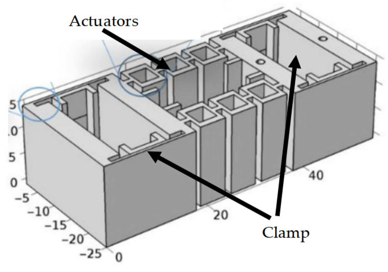
Mohammad [50] designed a uniaxial stepwise linear peristaltic piezoelectric motor (Figure 11), where the compiled voltage signals are transmitted to the drive circuit via LabVIEW programming and then transferred to the piezoelectric motor through an amplification circuit. This design features a simple structure and manufacturing process, offering advantages such as low production cost, high speed, and long travel range. By optimizing the structural parameters of the clamp and actuators, stiffness matching was achieved, ensuring the proper operation of the system. Experimental results indicate that the piezoelectric motor achieves a high resolution of 81 nm, with an average speed of 1.075 mm/s and a maximum operating frequency of 150 Hz under these conditions.
Yu [51] designed a micro-ridge piezoelectric peristaltic motor, This motor features a specialized micro-ridge structure, where micron-scale micro-teeth are fabricated on the surface of single-crystal silicon. These micro-teeth engage with each other to bear axial loads, thereby enhancing thrust output. This design enables the motor to generate up to 500 N of thrust and operate at a working frequency of 500 Hz. Experimental results demonstrate that the interlocking micro-ridge structure replaces traditional friction-based clamping, significantly improving the motor’s thrust output, stiffness, and stability.
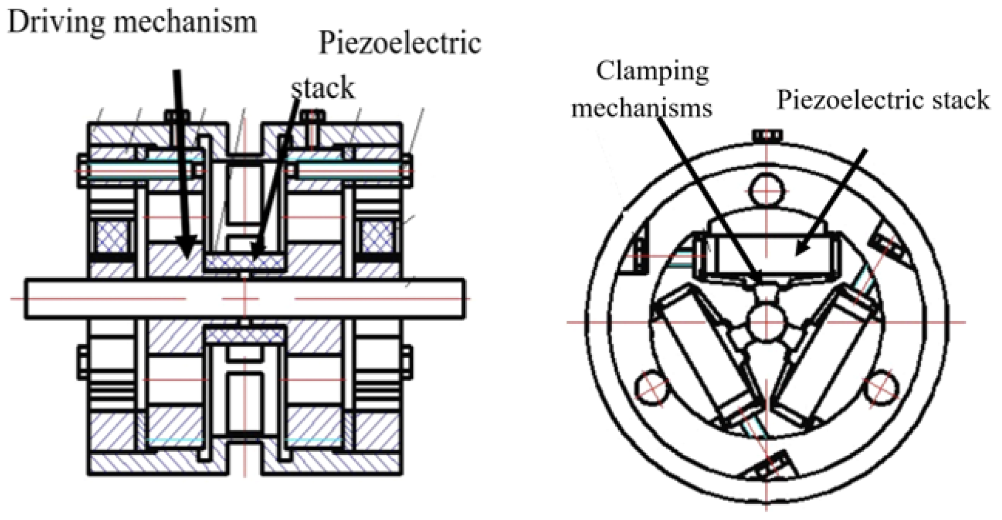
Huang [52] designed a cylindrical passive-clamping peristaltic motor (Figure 12), suitable for precision actuation and positioning in narrow spaces. The motor consists of a driving mechanism and two clamping mechanisms. It exhibits a static clamping friction force of 5 N, a maximum displacement resolution of 0.05 μm, and a maximum driving speed of 364 μm/s. Despite its compact size, the motor utilizes a triangular displacement amplification mechanism to enhance axial output force while maintaining good consistency and power-off self-locking capability. Additionally, this structure ensures zero axial clearance, enabling high-precision positioning.
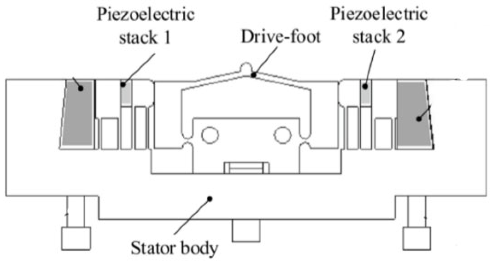
Chen [53] improved and optimized the stator structure of a flexible five-bar driven motor (Figure 13), establishing a structural model of the driving foot and deriving the elliptical motion trajectory equation of the driving end. Considering that longitudinal amplitude significantly affects the motor’s operational stability and output force, normal displacement was selected as the primary optimization parameter. After optimization, the driving foot achieved a balance between stiffness and normal displacement, bringing the motor’s mechanical performance close to optimal. Experimental results show that the stiffness of the improved driving foot increased by 84.21%, while the normal displacement amplitude of the driving tip improved by 58.5%.
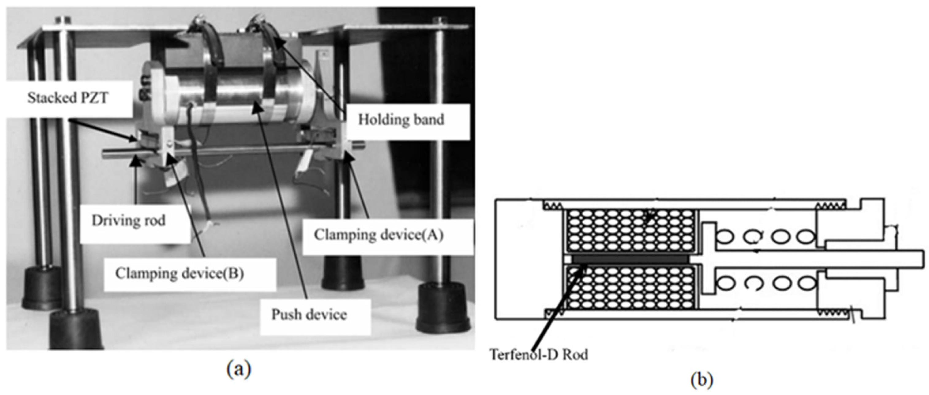
Kim [54] designed a hybrid linear motor that integrates piezoelectric and magnetostrictive actuation mechanisms to achieve high-precision and long-stroke motion control, as shown in Figure 14a. The clamping device employs multi-layer piezoelectric actuators to ensure sufficient clamping force, while the push device utilizes Terfenol-D magnetostrictive material to enhance the motor’s stroke length, as shown in Figure 14b.
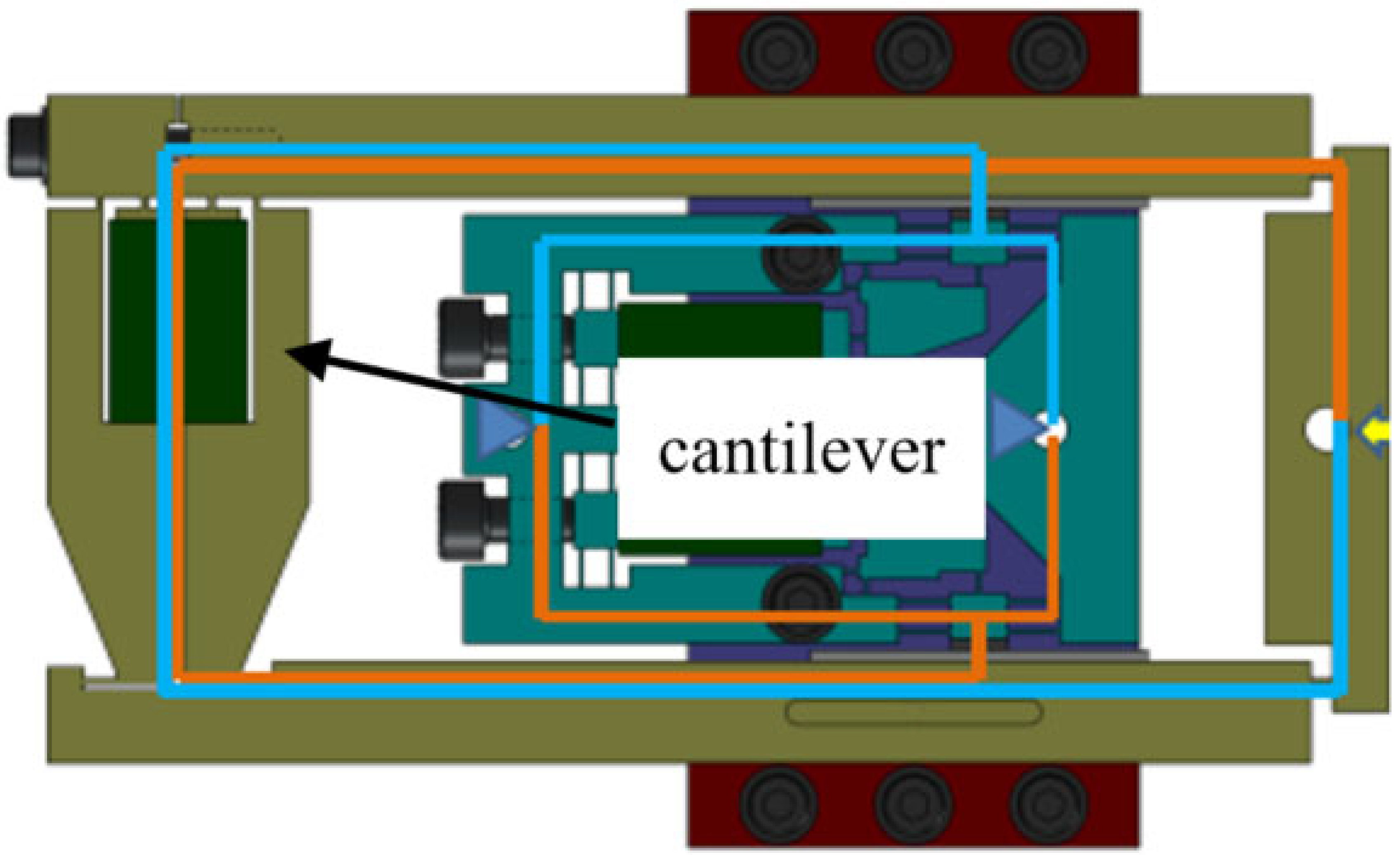
Edward [55] added a cantilever between the load and the motor’s extender (Figure 15), thereby increasing the stall load, which is the maximum load the motor can output. This structural modification enables the motor to withstand larger instantaneous loads, enhancing both thrust and system safety.
KWON [56] designed a linear peristaltic motor with a lever-based reduction mechanism (Figure 16), utilizing lever principles and a flexible structure to convert a large input displacement into a smaller output displacement. Experimental results demonstrated that the reduction lever mechanism effectively minimized positioning errors caused by controlled voltage fluctuations, thereby improving precision.
Mehmet [57] developed a low-voltage, high-thrust, large-displacement peristaltic piezoelectric motor, as shown in Figure 17. In their experiments, Mehmet et al. used an AT2313 microprocessor as the drive electronics and designed a control circuit board. At a working voltage of 7 V, the motor achieved a stroke of ±18 μm and an output force of ±30 μN. The results indicated that increasing the operating voltage led to a significant improvement in both stroke and output force. Ultimately, with 16 V and 10 V, the motor achieved total strokes of ±35 μm and ±24 μm, and output forces of ±110 μN and ±50 μN, respectively. Durability tests showed that the motor exhibited strong wear resistance, with no significant performance degradation after extensive cyclic operation.
Gu [58] proposed a rotary peristaltic piezoelectric motor, with its structure shown in Figure 18a. The working principle involves generating displacement and driving force through reverse voltage. A square wave voltage signal at a specific frequency controls the sequential expansion and contraction of four piezoelectric stacks, driving two driving mechanisms (DM) to produce alternating angular displacement. Meanwhile, two clamping mechanisms (CM) alternately grip the rotor, enabling motor motion, as shown in Figure 18b.
Li [59] developed a rotary peristaltic motor with an L-shaped driving block, as shown in Figure 19a. The motor stator consists of two layers connected by flexible hinges, with each layer housing three independent piezoelectric stacks and clamping units to grip and release the central rotor. The lower end of the L-shaped driving block is mounted on the lower layer of the stator, while its upper end remains detached from the stator, as shown in Figure 19b. When the piezoelectric stacks in the driving mechanism expand, they push the upper layer of the stator, causing it to rotate relative to the lower layer by a certain angle. The flexible hinges connecting the two layers facilitate the resetting motion during relative rotation.
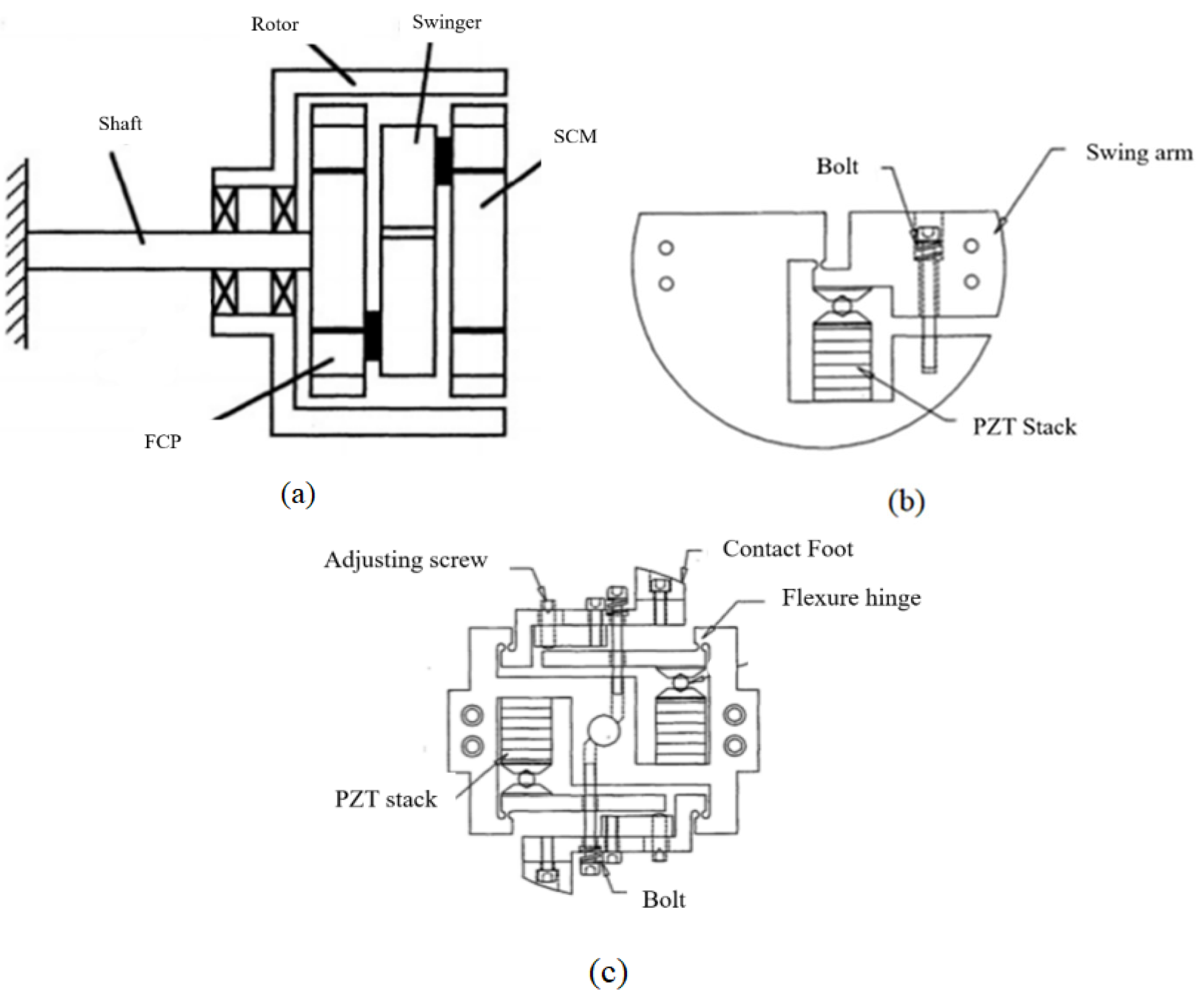
Duong [60] proposed a rotary piezoelectric motor structure, as shown in Figure 20a. This motor consists of four main components: two clamping mechanisms (Figure 20b), one swing mechanism, and one rotor. The clamping mechanism utilizes the lever amplification principle to increase the displacement of the contact foot. Bolts in the mechanism allow precise adjustments to both the position of the contact foot and the preload force exerted on the rotor. When the piezoelectric stack expands, the contact foot extends to clamp the rotor. The swing mechanism (Figure 20c) has a fixed part, which is secured to one of the clamping mechanisms (FCM) using bolts, serving as the fixed end. The oscillating arm is connected to the other clamping mechanism (SCM) via bolts. When the piezoelectric stack expands, the oscillating arm rotates around the flexible hinge, causing the SCM to rotate accordingly. When the piezoelectric stack contracts, the SCM returns to its initial position along with the swing arm. The clamping mechanism and swing mechanism are assembled inside the rotor, where the clamping mechanisms alternately grip the rotor, while the swing mechanism provides angular displacement, ultimately enabling the continuous rotation of the rotor.
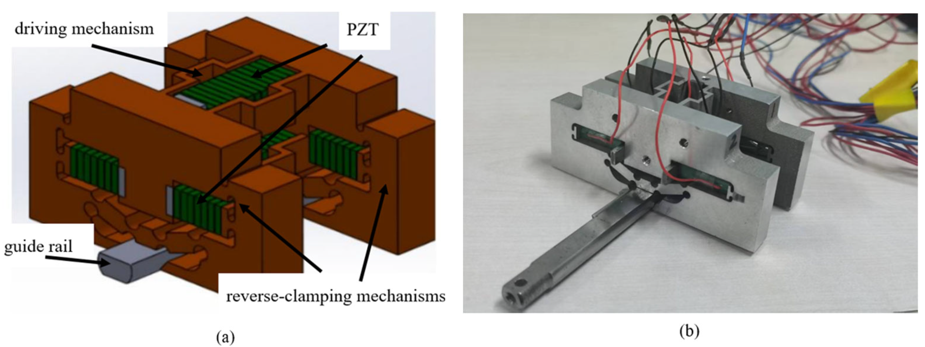
Our research team proposed a reverse-clamping peristaltic linear actuator [61], composed of two reverse-clamping mechanisms and one driving mechanism, as shown in Figure 21a. The reverse-clamping mechanism employs both the triangular displacement amplification principle and the lever amplification principle, allowing the clamping foot to open when powered on and tighten onto the guide rail when powered off. This design grants the reverse-clamping motor advantages such as power-off self-locking and high positioning accuracy. Adhering to an integrated structural design approach, we implemented a monolithic fabrication process for the reverse-clamping mechanism and driving mechanism, effectively addressing issues related to low circumferential positioning accuracy and insufficient clamping force. Experimental results indicate that the maximum static clamping force of a single clamping mechanism reaches 14 N, while the maximum driving force is 4 N. Additionally, at a driving voltage of 30 V, the motor achieves a displacement resolution of 0.4 μm.

4. Other Piezoelectric Motors

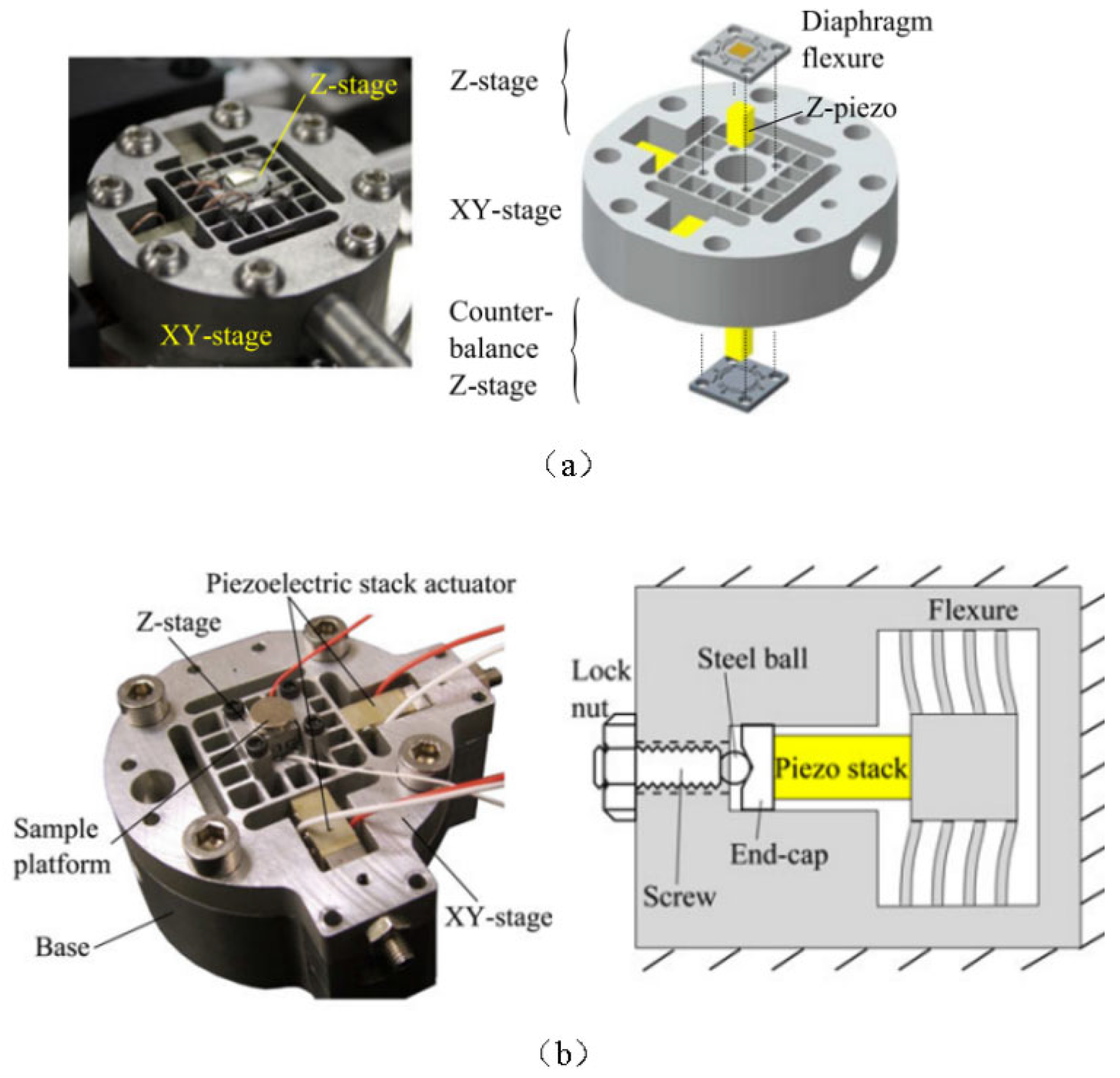
Yong [62] et al. developed a three-dimensional stage that utilizes an inertial motor as the actuator, as shown in Figure 22a. At excitation frequencies of 20 kHz and 60 kHz, the stage is capable of achieving nanoscale motion in both the vertical and horizontal directions. Since the motor lacks a transmission mechanism, it offers an extremely fast response time of just 10 µs and a displacement control accuracy better than 0.01 μm. To extend the travel range, an improved version of the motion stage incorporates a lever amplification mechanism, as shown in Figure 22b, enabling displacements at the micron scale [63]. Theoretically, the travel range of a direct-drive piezoelectric motor is directly related to the deformation of the piezoelectric ceramic, making it challenging to achieve large travel distances.
Piezoelectric inertial drive operates based on the momentum theorem, utilizing the interaction between an inertial mass and a piezoelectric stack to generate motion. Its advantages include a simple structure, the capability for high-speed motion, and multi-degree-of-freedom movement. However, it also has notable drawbacks: it requires high precision in dynamic design, machining accuracy, and drive control signals, while its driving force is relatively small. The most critical challenge of piezoelectric inertial drive is that it functions as an open-loop system, making control-particularly positioning and holding-difficult, which has limited its applications.

5. Discussion

Table 1 provides a qualitative comparison of the key performance characteristics of three representative piezoelectric motor types: ultrasonic motor, inertial motor, and peristaltic motor. Each type exhibits unique operational advantages and inherent trade-offs depending on the intended application scenario.
Ultrasonic motors achieve the highest running speed, reaching up to approximately 200 mm/s, and are therefore suitable for high-speed motion applications such as camera autofocus, robotic actuation, and precision mechanical positioning. However, their operation relies on high-frequency frictional contact between the stator and rotor, which inevitably leads to heat generation and wear, reducing both efficiency and long-term stability. Structural complexity and waveform control also contribute to their relatively difficult control characteristics.
Inertial motors provide medium operating speed and comparable resolution (around 100 nm), achieved through stick–slip or impact drive mechanisms. Their simple structure offers advantages in compactness and ease of fabrication, but their limited load capacity, low positioning stability, and restricted motion trajectory (non-supporting curved motion) make them more suitable for micro-positioning stages or atomic force microscopy applications where minimal displacement and low force are required.
Peristaltic motors, in contrast, combine high positioning stability and fine resolution (as small as 20 nm) with low operating frequency and minimal heat generation. Their peristaltic drive sequence allows precise and stable displacement through coordinated phase timing, while maintaining high efficiency. Despite their structural complexity and control difficulty, they are advantageous for applications that demand both precision and reliability, such as optical alignment, aerospace mechanisms, and vacuum operation systems.
In summary, ultrasonic motors dominate in speed-oriented tasks, inertial motors excel in compact ultra-fine positioning applications, and peristaltic motors offer the best balance between efficiency, precision, and thermal stability.
This comprehensive comparison highlights the importance of selecting appropriate motor types according to performance requirements and control complexity in advanced electromechanical systems.

6. Conclusions and Trends

Compared with traditional motors, piezoelectric motors have advantages in terms of weight, size, driving torque, and structural design. Piezoelectric motors with different principles and structures each have their own strengths in terms of travel range, speed, precision, and load capacity. Currently, ultrasonic motors and peristaltic motors have attracted the highest attention and have the widest range of applications.
Over the past decade, ultrasonic motors have evolved from single-mode to composite-mode structures, achieving higher torque density and control precision. Meanwhile, peristaltic motors have gained attention for applications requiring large load capacity and long-term stability. Future research will focus on lightweight integrated designs, friction optimization for vacuum operation, and intelligent adaptive control methods.
Ultrasonic motors feature high speed, compact structure, and a wide torque range. However, they have a relatively long steady-state time, which leads to a sharp drop in precision during low-speed operation and ultra-short displacement. To address the nonlinearity issue of ultrasonic motors, designing new motor structures (such as rhombic vibrators) or proposing new control methods (such as instantaneous driving) has become the current mainstream trend. In the aerospace field, the impact of temperature on the performance of motor friction materials is also a key research focus.
Peristaltic motors offer large load capacity, high precision, and power-off holding functionality. Nevertheless, their high precision is particularly dependent on high-precision guiding mechanisms. Therefore, the integrated design of peristaltic motors and guiding mechanisms is the current mainstream trend. In the aerospace field, Long-term operation may lead to contact cold welding; temperature changes can affect the piezoelectric constant, thereby reducing positioning accuracy. Future research should focus on temperature compensation control and anti-adhesion material design to improve reliability in aerospace missions. The cold welding issue of motor clamping mechanisms and the weight reduction of the overall motor are also hot topics in current research.

Funding

This research was funded by National Natural Science Foundation of China: 52205042 and Young Elite Scientists Sponsorship Program by CAST: 2022QNRC001.

Institutional Review Board Statement

Not applicable.

Informed Consent Statement

Not applicable.

Data Availability Statement

No new data were created or analyzed in this study. Data sharing is not applicable to this article.

Conflicts of Interest

The authors declare no conflict of interest.

References

  1. Wu, Y.; Chang, S.; Wu, H. Research on Radial Dynamic Performance of Air Float supported Contact Needle Measurement System. Aviat. Manuf. Technol. 2021, 64, 48–54. [Google Scholar]
  2. Morita, T. Miniature piezoelectric motors. Sens. Actuators A Phys. 2003, 103, 291–300. [Google Scholar] [CrossRef]
  3. Spanner, K.; Koc, B. Piezoelectric motors, an overview. Actuators 2016, 5, 6. [Google Scholar] [CrossRef]
  4. Chen, W.; Liu, Y.; Liu, Y.; Tian, X.; Shan, X.; Wang, L. Design and experimental evaluation of a novel stepping linear piezoelectric actuator. Sens. Actuators A Phys. 2018, 276, 259–266. [Google Scholar] [CrossRef]
  5. Shi, S.; Huang, Z.; Yang, J.; Liu, Y.; Chen, W.; Uchino, K. Development of a compact ring type MDOF piezoelectric ultrasonic motor for humanoid eyeball orientation system. Sens. Actuators A Phys. 2018, 272, 1–10. [Google Scholar] [CrossRef]
  6. Kuhne, M.; Rochin, R.G.; Cos, R.S.; Astorga, G.J.R.; Peer, A. Modeling and two-input sliding mode control of rotary traveling wave ultrasonic motors. IEEE Trans. Ind. Electron. 2018, 65, 7149–7159. [Google Scholar] [CrossRef]
  7. Zhao, G.; Wu, C.; Zhang, L.; Song, J.; Ding, Q. Friction and wear behavior of PI and PTFE composites for ultrasonic motors. Polym. Adv. Technol. 2018, 29, 1487–1496. [Google Scholar] [CrossRef]
  8. Yang, L.; Wang, F.; Zhang, J.; Ren, W. Remaining useful life prediction of ultrasonic motor based on Elman neural network with improved particle swarm optimization. Meas. J. Int. Meas. Confed. 2019, 143, 27–38. [Google Scholar] [CrossRef]
  9. Qu, H.; Wen, Z.; Qu, J.; Song, B. Study on effects of ultrasonic vibration on sliding friction properties of PTFE composites/phosphor bronze under vacuum. Vacuum 2019, 164, 1–6. [Google Scholar] [CrossRef]
  10. Yin, Z.; Dai, C.; Cao, Z.; Li, W.; Chen, Z.; Li, C. Modal analysis and moving performance of a single-mode linear ultrasonic motor. Ultrasonics 2020, 108, 106216. [Google Scholar] [CrossRef]
  11. Tian, X.; Liu, Y.; Deng, J.; Wang, L.; Chen, W. A review on piezoelectric ultrasonic motors for the past decade: Classification, operating principle, performance, and future work perspectives. Sens. Actuators A Phys. 2020, 306, 111971. [Google Scholar] [CrossRef]
  12. Deng, J.; Liu, Y.; Liu, J.; Xu, D.; Wang, Y. Development of a planar piezoelectric actuator using bending-bending hybrid transducers. IEEE Trans. Ind. Electron. 2019, 66, 6141–6149. [Google Scholar] [CrossRef]
  13. Wu, J.; Mizuno, Y.; Nakamura, K. Polymer-based ultrasonic motors utilizing high-order vibration modes. IEEE/ASME Trans. Mechatron. 2018, 23, 788–799. [Google Scholar] [CrossRef]
  14. Wang, L.; Quan, Q.; Xue, K.; Li, H. Development of a three-DOF piezoelectric actuator using a thin cross-beam vibrator. Int. J. Mech. Sci. 2018, 149, 54–61. [Google Scholar] [CrossRef]
  15. Zhang, Y.; Fu, Y.; Hua, X.; Quan, L.; Qu, J. Wear debris of friction materials for linear standing-wave ultrasonic motors: Theory and experiments. Wear 2020, 448–449, 203216. [Google Scholar] [CrossRef]
  16. Jiang, Z.; Wang, L.; Jin, J. A novel robotic arm driven by sandwich piezoelectric transducers. Ultrasonics 2018, 84, 373–381. [Google Scholar] [CrossRef]
  17. Mohith, S.; Upadhya, A.R.; Navin, K.P.; Kulkarni, S.M.; Rao, M. Recent trends in piezoelectric actuators for precision motion and their applications: A review. Smart Mater. Struct. 2021, 30, 053001. [Google Scholar] [CrossRef]
  18. Gao, X.; Yang, J.; Wu, J.; Xin, X.; Li, Z.; Yuan, X.; Shen, X.; Dong, S. Piezoelectric actuators and motors: Materials, designs, and applications. Adv. Mater. Technol. 2020, 5, 1900716. [Google Scholar] [CrossRef]
  19. Wang, L.; Hofmann, V.; Bai, F.; Jin, J.; Twiefel, J. Modeling of coupled longitudinal and bending vibrations in a sandwich type piezoelectric transducer utilizing the transfer matrix method. Mech. Syst. Signal Process. 2018, 108, 216–237. [Google Scholar] [CrossRef]
  20. Hariri, H.; Bernard, Y.; Razek, A. 2-D traveling wave driven piezoelectric plate robot for planar motion. IEEE/ASME Trans. Mechatron. 2018, 23, 242–251. [Google Scholar] [CrossRef]
  21. Zhang, Y.; Fu, Y.; Hua, X.; Quan, L.; Qu, J. Characteristics and attenuation mechanism of linear standing-wave piezoelectric motors with ceramics-mated friction couples. Tribol. Int. 2021, 153, 106580. [Google Scholar] [CrossRef]
  22. Ryndzionek, R.; Sienkiewicz, Ł. A review of recent advances in the single- and multi-degree-of-freedom ultrasonic piezoelectric motors. Ultrasonics 2021, 116, 106475. [Google Scholar] [CrossRef] [PubMed]
  23. Tian, X.; Liu, Y.; Chen, W.; Deng, J.; Liu, J. Development and experiment evaluation of an H-shape linear piezoelectric actuator operated in stepping mode. Ceram. Int. 2018, 44, S246–S249. [Google Scholar] [CrossRef]
  24. Li, J.; Huang, H.; Zhao, H. A piezoelectric-driven linear actuator by means of coupling motion. IEEE Trans. Ind. Electron. 2018, 65, 2458–2466. [Google Scholar] [CrossRef]
  25. Qu, H.; Liu, C.; Zhang, L.; Qu, J.; Song, B. A longitudinal-bending hybrid linear ultrasonic motor and its driving characteristic. Shock Vib. 2022, 2022, 5701014. [Google Scholar] [CrossRef]
  26. Peled, G.; Yasinov, R.; Karasikov, N. Performance and applications of L1B2 ultrasonic motors. Actuators 2016, 5, 6. [Google Scholar] [CrossRef]
  27. Li, X.; Kan, C.; Cheng, Y.; Chen, Z.; Ren, T. Performance evaluation of a bimodal standing-wave ultrasonic motor considering nonlinear electroelasticity: Modeling and experimental validation. Mech. Syst. Signal Process. 2020, 141, 106475. [Google Scholar] [CrossRef]
  28. Jian, Y.; Yao, Z.; Silberschmidt, V.V. Linear ultrasonic motor for absolute gravimeter. Ultrasonics 2017, 78, 54–61. [Google Scholar] [CrossRef]
  29. Izuhara, S.; Mashimo, T. Design and characterization of a thin linear ultrasonic motor for miniature focus systems. Sens. Actuators A Phys. 2021, 329, 112797. [Google Scholar] [CrossRef]
  30. Uchino, K. Piezoelectric ultrasonic motors: Overview. Smart Mater. Struct. 1998, 7, 273–285. [Google Scholar] [CrossRef]
  31. Wu, J.; Mizuno, Y.; Nakamura, K. Structural parameter study on polymer-based ultrasonic motor. Smart Mater. Struct. 2017, 26, 115022. [Google Scholar] [CrossRef]
  32. Li, X.; Li, X.; Li, T.; Zhang, Y. Development of a compact solar array drive assembly based on ultrasonic motor for deep space micro-nano satellites. Acta Astronaut. 2025, 228, 865–874. [Google Scholar] [CrossRef]
  33. Liang, Y.; Pan, S.; Chen, L. Design of optoelectronic tracking platform driven by ultrasonic motor with a novel limiter. Micromachines 2023, 14, 13. [Google Scholar] [CrossRef] [PubMed]
  34. Wang, L.; Liu, J.; Liu, Y.; Tian, X.; Yan, J. A novel single-mode linear piezoelectric ultrasonic motor based on asymmetric structure. Ultrasonics 2018, 89, 137–142. [Google Scholar] [CrossRef] [PubMed]
  35. Yang, L.; Ma, C.; Ren, W.; Zhang, J. Beat traveling wave principle and its verification on rotating ultrasonic motor. J. Vib. Control 2020, 27, 2354–2367. [Google Scholar] [CrossRef]
  36. Yamashita, T.; Mashimo, T.; Takesue, N.; Terashima, K. Safeness of a robot arm using ultrasonic motors with high responsiveness and backdrivability. In Proceedings of the IEEE/SICE International Symposium on System Integration, Tokyo, Japan, 14–17 December 2014; pp. 13–18. [Google Scholar]
  37. Toyama, S. Spherical Ultrasonic Motor for Pipe Inspection Robot. Appl. Mech. Mater. 2012, 186, 3–11. [Google Scholar] [CrossRef]
  38. Liu, C.D. Study on Rhombic Linear Ultrasonic Motor. Master’s Thesis, Harbin Institute of Technology, Harbin, China, 2022. [Google Scholar]
  39. Kurosawa, M.K.; Kodaira, O.; Tsuchitoi, Y.; Higuchi, T. Transducer for high speed and large thrust ultrasonic linear motor using two sandwich-type vibrators. IEEE Trans. Ultrason. Ferroelectr. Freq. Control 1998, 45, 1188–1196. [Google Scholar] [CrossRef]
  40. Jeong, S.S.; Park, T.G.; Kim, M.H.; Song, T.K. Characteristics of a V-type ultrasonic rotary motor. Curr. Appl. Phys. 2011, 11, 364–367. [Google Scholar] [CrossRef]
  41. Li, X.; Yao, Z.; Yang, M. A novel large thrust-weight ratio V-shaped linear ultrasonic motor with a flexible joint. Rev. Sci. Instrum. 2017, 88, 065003. [Google Scholar] [CrossRef]
  42. Qiu, W.; Mizuno, Y.; Koyama, D.; Nakamura, K. Efficiency improvement of hybrid transducer-type ultrasonic motor using lubricant. IEEE Trans. Ultrason. Ferroelectr. Freq. Control 2013, 60, 786–794. [Google Scholar] [CrossRef]
  43. Yan, J.; Liu, Y.; Liu, J.; Xu, D.; Chen, W. The design and experiment of a novel ultrasonic motor based on the combination of bending modes. Ultrasonics 2016, 71, 205–210. [Google Scholar] [CrossRef]
  44. Wu, J.; Mizuno, Y.; Nakamura, K. A rotary ultrasonic motor operating in torsional/bending modes with high torque density and high power density. IEEE Trans. Ind. Electron. 2021, 68, 6109–6120. [Google Scholar] [CrossRef]
  45. Li, X.; Wen, Z.; Jia, B.; Wu, D. A review of application and development trends in ultrasonic motors. ES Mater. Manuf. 2020, 12, 3–16. [Google Scholar] [CrossRef]
  46. Liu, W.; Yang, Z.; Jiang, S.; Feng, D.; Zhang, D. Design and implementation of a new cable-driven robot for MRI-guided breast biopsy. Int. J. Med. Robot. Comput. Assist. Surg. 2020, 16, e2063. [Google Scholar] [CrossRef] [PubMed]
  47. Wu, W.; Li, C.; Zuo, W.; Zhang, H.; Liu, J.; Wen, W.; Ouyang, Z. Lunar farside to be explored by Chang’e-4. Nat. Geosci. 2019, 12, 222–223. [Google Scholar] [CrossRef]
  48. Sun, Z.; Zhang, T.; Zhang, H.; Jia, Y.; Zhang, H.; Chen, J.; Wu, X.; Shen, Z. The technical design and achievements of Chang’E-3 probe. Sci. China Technol. Sci. 2014, 4, 13. [Google Scholar]
  49. Jana, S.; Shome, S.K.; Nandi, A.K. A novel four-legged linear piezoelectric peristaltic motor with high thrust force. Microsyst. Technol. 2024, 31, 161–175. [Google Scholar] [CrossRef]
  50. Sangchap, M.; Tahmasebipour, M.; Tahmasebipour, Y. A linear peristaltic piezomotor with a new configuration: Design considerations, fabrication and characterization. Iran. J. Sci. Technol. Trans. Mech. Eng. 2022, 46, 149–160. [Google Scholar] [CrossRef]
  51. Yu, Y.; Li, W. A high-thrust peristaltic piezoelectric linear motor. Small Spec. Electr. Mach. 2001, 05, 29–31. [Google Scholar]
  52. Huang, H. Research on Cylindrical Passive Clamping Piezoelectric Peristaltic Linear Motor. Master’s Thesis, Harbin Institute of Technology, Harbin, China, 2013. [Google Scholar]
  53. Chen, X.; Li, M.; Zhang, H.; Lu, Q.; Lyu, S. Improvement on the structure design of a kind of linear piezoelectric motor with flexible drive-foot. Int. J. Precis. Eng. Manuf. 2020, 21, 81–89. [Google Scholar] [CrossRef]
  54. Kim, J.; Kim, H.-K.; Choi, S.-B. A hybrid peristaltic linear motor. Mechatronics 2002, 12, 525–542. [Google Scholar] [CrossRef]
  55. Williams, E.; Loveday, P.; Theron, N. Design of a large-force piezoelectric peristaltic motor with a force duplicator. In Proceedings of the 2013 6th Robotics and Mechatronics Conference (RobMech), Durban, South Africa, 30–31 October 2013; pp. 46–51. [Google Scholar]
  56. Kwon, K.; Cho, N.; Jang, W. The design and characterization of a piezo-driven peristaltic linear motor with a reduction-lever mechanism. JSME Int. J. Ser. C Mech. Syst. Mach. Elem. Manuf. 2004, 47, 803–811. [Google Scholar]
  57. Erismis, M.A. A low-voltage large-displacement large-force peristaltic actuator. J. Microelectromechanical Syst. 2008, 17, 1294–1301. [Google Scholar] [CrossRef]
  58. Gu, Y.; Xing, J. Dynamics analysis for the clamping mechanisms of a rotary peristaltic piezoelectric motor. J. Vibroengineering 2016, 18, 2229–2239. [Google Scholar] [CrossRef]
  59. Li, J. A piezoelectric-driven rotary actuator by means of peristaltic motion. Sens. Actuators A Phys. 2013, 194, 269–276. [Google Scholar] [CrossRef]
  60. Duong, K.; Garcia, E. Design and performance of a rotary motor driven by piezoelectric stack actuators. Jpn. J. Appl. Phys. 1996, 35, 6334–6341. [Google Scholar] [CrossRef]
  61. Hu, M.M. Research on a Compound Amplified Passive-Clamping Piezoelectric Peristaltic Linear Actuator. Master’s Thesis, Harbin Institute of Technology, Harbin, China, 2018. [Google Scholar]
  62. Yong, Y.K.; Moheimani, S.O.R. Collocated Z-axis control of a high-speed nanopositioner for video-rate atomic force microscopy. IEEE Trans. Nanotechnol. 2015, 14, 338–345. [Google Scholar] [CrossRef]
  63. Yong, Y.K.; Bhikkaji, B.; Moheimani, S.O.R.R. Design, modeling, and FPAA-based control of a high-speed atomic force microscope nanopositioner. IEEE/ASME Trans. Mechatron. 2013, 18, 1060–1071. [Google Scholar] [CrossRef]
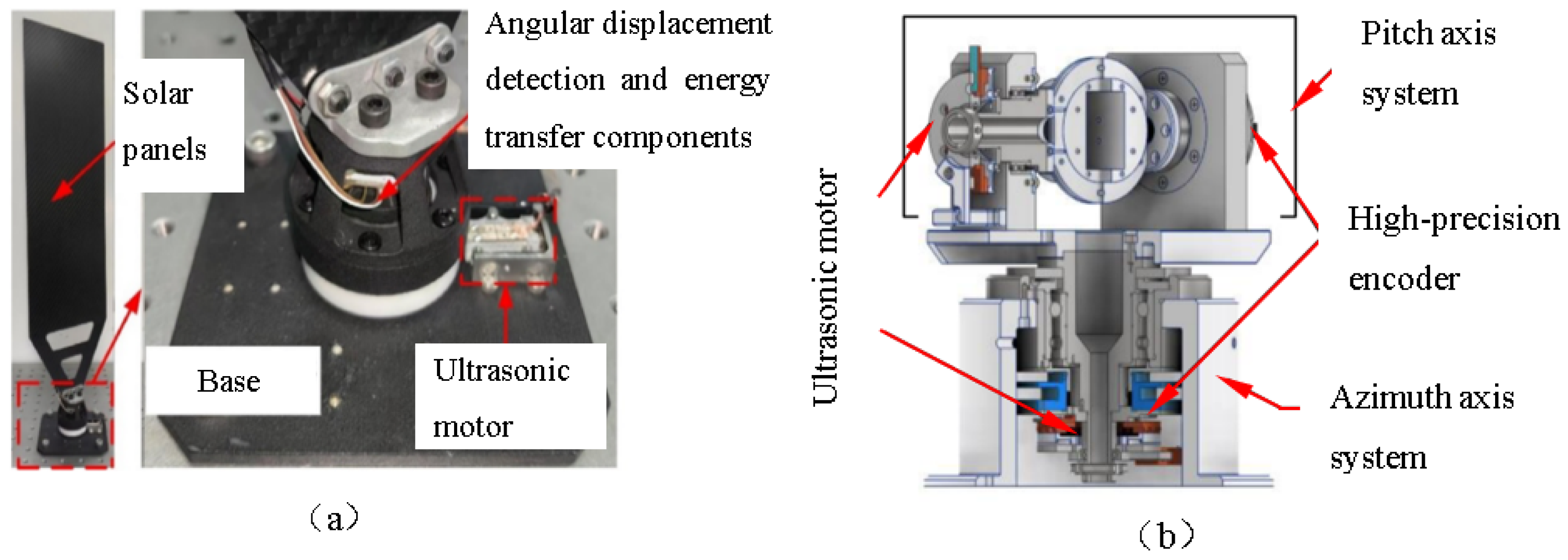
Figure 1. Ultrasonic Motor Applications. (a) Solar array [32]; (b) Tracking positioning system [33].
Applsci 15 12510 g001
Figure 2. Standing-Wave Ultrasonic Motor [34]. (a) Stator structure; (b) Operating principle.
Applsci 15 12510 g002
Figure 3. Traveling-Wave Ultrasonic Motor [35]. (a) Structure; (b) Operating principle.
Applsci 15 12510 g003
Figure 4. Applications of Ultrasonic Motors. (a) Robotic arm [36]; (b) Pipe inspection [37].
Applsci 15 12510 g004
Figure 5. Structure Diagram V-shaped Ultrasonic Motors. (a) Stacked type [39]; (b) Side-attached type.
Applsci 15 12510 g005
Figure 6. Longitudinal–Torsional Composite Modal Ultrasonic Motor [42].
Applsci 15 12510 g006
Figure 7. Bending–Bending Composite Modal Ultrasonic Motor [43].
Applsci 15 12510 g007
Figure 8. Bending–Torsional Composite Modal Ultrasonic Motor [44]. (a) Motor Structure Diagram (b) Motor Assembly Diagram.
Applsci 15 12510 g008
Figure 9. A measurement method proposed by our research team. (a) Measuring method; (b) measuring device; (c) measuring principle.
Applsci 15 12510 g009
Figure 10. Structural Diagram of the Quadruped Piezoelectric Peristaltic Motor [49].
Applsci 15 12510 g010
Figure 11. Structural Diagram of the Uniaxial Stepwise Linear Piezoelectric Motor [50].
Applsci 15 12510 g011
Figure 12. Structural Diagram of the Cylindrical Passive-Clamping Piezoelectric Motor [52].
Applsci 15 12510 g012
Figure 13. Structural Diagram of the Flexible Five-Bar Driven Motor [53].
Applsci 15 12510 g013
Figure 14. The hybrid linear motor [54]. (a) Photograph of the hybrid linear motor; (b) Terfenol-D actuator for push device.
Applsci 15 12510 g014
Figure 15. Structural Diagram of the Piezoelectric Peristaltic Motor with a Cantilever [55].
Applsci 15 12510 g015
Figure 16. Structural Diagram of the Peristaltic Linear Motor with a Lever-Based Reduction Mechanism [56].
Applsci 15 12510 g016
Figure 17. Structural Diagram of the Low-Voltage, Large-Displacement, High-Thrust Peristaltic Piezoelectric Motor [57].
Applsci 15 12510 g017
Figure 18. The Rotary Peristaltic Piezoelectric Motor [58]. (a) Structural Diagram of the Motor; (b) Driving principle Diagram of the Rotary Peristaltic Piezoelectric Motor.
Applsci 15 12510 g018
Figure 19. The Rotary Piezoelectric Motor [59]. (a) Structural Diagram of the Rotary Piezoelectric Motor; (b) The Driving Mechanism.
Applsci 15 12510 g019
Figure 20. The rotary piezoelectric motor structure [60]. (a) Motor assembly diagram; (b) structural diagram of the swing mechanism; (c) structural diagram of the clamping mechanism.
Applsci 15 12510 g020
Figure 21. The reverse-clamping peristaltic linear actuator [61]. (a) Structural Diagram of the Reverse-Clamping Peristaltic Linear Actuator; (b) Physical Diagram of the Actuator.
Applsci 15 12510 g021
Figure 22. (a) Inertial motor for driving the three-dimensional stage before the improvement stage [62]; (b) improved stage [63].
Applsci 15 12510 g022
Table 1. Performance characteristics of piezoelectric drive motors with different principles in various aspects.
PrincipleUltrasonic MotorInertial MotorPeristaltic Motor
TripLarge itineraryLarge itineraryLarge itinerary
Running speedExtremely high
(200 mm/s)
MediumMedium (0.5 mm/s)
Resolution100 nm100 nm20 nm
Positioning stabilityMediumLowHigh
LoadMediumLowHigh
FrequencyHighMediumLow
FrictionHigh frictionFrictionalSlight friction
FeverFeverMild feverNo fever
Energy efficiencyInefficientRelatively high efficientHigh efficient
Structural complexityRelatively highRelatively LowHigh
Control characteristicsSpecific waveformSpecific waveformSpecific timing sequence
Control difficultyComplexEasyComplex
Curve trajectorySupportingForbiddenSupporting
Disclaimer/Publisher’s Note: The statements, opinions and data contained in all publications are solely those of the individual author(s) and contributor(s) and not of MDPI and/or the editor(s). MDPI and/or the editor(s) disclaim responsibility for any injury to people or property resulting from any ideas, methods, instructions or products referred to in the content.