Article

Robust Path-Tracking Control for Autonomous Vehicles: A Model-Reference-Adaptive-Control-Based Integrated Chassis Control Strategy

by
Siyeong Park
1,
Taeyoung Oh
1,
Jeesu Kim
2 and
Jinwoo Yoo
3,*
1
Graduate School of Automotive Engineering, Kookmin University, Seoul 02707, Republic of Korea
2
Department of Cogno-Mechatronics Engineering, Pusan National University, Busan 46241, Republic of Korea
3
Department of Automobile and IT Convergence, Kookmin University, Seoul 02707, Republic of Korea
*
Author to whom correspondence should be addressed.
Appl. Sci. 2025, 15(23), 12387; https://doi.org/10.3390/app152312387
Submission received: 19 October 2025 / Revised: 19 November 2025 / Accepted: 20 November 2025 / Published: 21 November 2025

Abstract

Autonomous vehicles are often subjected to disturbances that compromise path-tracking accuracy and stability. Traditional chassis controllers that rely on fixed vehicle models exhibit performance limitations under such uncertainties. To address this challenge, we propose an adaptive integrated chassis control strategy that combines a linear quadratic regulator (LQR) and a model reference adaptive control (MRAC) framework. The LQR component generates nominal control commands, while the MRAC framework compensates in real time for model uncertainties and external disturbances. Simulation studies conducted in CarMaker and MATLAB/Simulink indicate that the proposed controller substantially improves path-tracking performance. Compared with conventional methods, the proposed controller reduces the root mean square error, peak error, and integral of the absolute error by up to 25.2%, 33.5%, and 34.6%, respectively. Overall, the proposed adaptive chassis controller shows enhanced vehicle robustness and stability in simulation under challenging driving conditions.

1. Introduction

With the continuous advancement of autonomous driving technology and vehicle electrification, integrated chassis control, which links vehicle motion control with individual actuator coordination, has become increasingly vital [1,2]. This growing importance is reflected in contemporary electric autonomous vehicle designs, which are equipped with various chassis actuators, such as braking systems, electric-motor-based torque vectoring, and active steering mechanisms. When coordinated effectively, these actuators contribute substantially to both vehicle performance and driving stability [1,2,3]. Among the functionalities enabled by such coordinated control, path tracking plays a key role, allowing autonomous vehicles to reliably follow planned trajectories. Any deviation from the intended path, such as unintended lane departures or erratic lane changes, can present serious safety hazards [4]. Therefore, high-precision and reliable path tracking control is essential to ensure safe autonomous driving. Moreover, as vehicle control systems become increasingly sophisticated through autonomy and electrification, integrating vehicle dynamics control with actuator coordination becomes essential for precise path tracking [1,5,6].
In practice, however, autonomous vehicles are exposed to a combination of uncertainties that compromise path tracking accuracy and vehicle stability. These challenges can be categorized as: (i) external disturbances, such as crosswind forces and road irregularities; (ii) parameter variations from the nominal model, including fluctuations in vehicle mass, speed, and cornering stiffness (which varies due to changes in road surface friction); and (iii) modeling errors. To illustrate the impact, Liu et al. investigated stability under crosswind conditions [5], while Liu et al. proposed a coordinated strategy for potholed roads [7]. Their findings revealed that conventional controllers lacking in disturbance compensation may perform poorly under these combined real-world conditions. Therefore, ensuring robust path tracking against this multi-faceted uncertainty is critical for autonomous vehicle safety, and numerous strategies have recently been introduced to address this need [8,9,10].
Among these strategies, integrated chassis control leveraging the over-actuated architecture of modern vehicles has garnered extensive attention. To improve path-tracking accuracy, several studies have employed lateral dynamics control using actuators such as direct yaw-moment control (DYC), implemented via individual wheel torque distribution, and active rear steering [1,11,12,13,14,15]. For instance, some studies developed a path tracking controller that integrated model predictive control (MPC) with torque vectoring for four-wheel independent electric vehicles, achieving high path-tracking precision [16,17]. In a related effort, Zhang et al. introduced a coordinated control strategy for four-wheel independent drive autonomous vehicles by combining an MPC-based adaptive path tracking controller with a sliding-mode-based stability controller. This approach resolved the trade-off between tracking accuracy and vehicle stability and demonstrated improved performance under extreme driving conditions in simulation studies [18]. In addition to these, coordinated control strategies integrating lateral steering control with drive motor control have also been proposed to minimize path deviation and maintain stability on irregular road surfaces, such as those affected by potholes [16,19]. Also, four-wheel independent-drive electric vehicles using adaptive sliding mode control have been reported to maintain performance and stability on low-friction surfaces by flexibly redistributing individual wheel forces [20,21,22]. As a representative torque vectoring-based fault tolerant approach, Meléndez-Useros et al. proposed a static output-feedback path-tracking controller that switches to torque-vectoring assistance under steering-actuator degradation or saturation and reported significant reductions in lateral and heading errors [23].
Despite these diverse applications of integrated chassis control, current approaches continue to face several limitations.
  • Adding actuators or applying basic coordination strategies alone may not adequately address model uncertainties or external disturbances. For instance, determining front and rear steering angles in 4 WS vehicles based on nominal models has been criticized for underutilizing the system’s capabilities, resulting in limited performance gains [24].
  • Traditional robust control strategies accounting for disturbances may be constrained by conservative designs necessary for stability guarantees, which may limit optimal tracking performance under varied operating conditions [8,25].
In this context, adaptive chassis control strategies that automatically compensate for disturbances or adjust parameters based on driving conditions have received growing attention in the integrated chassis control field.
Motivated by these considerations, we incorporate model reference adaptive control (MRAC) into the vehicle chassis control architecture to enhance robustness against disturbances and to ensure consistent tracking performance—capabilities that cannot be easily achieved through basic actuator augmentation alone. MRAC is an adaptive control method that continuously updates control parameters in real time to minimize tracking errors between the actual vehicle response and a reference model, thereby compensating for system uncertainties [26,27,28,29,30].
Unlike conventional adaptive controllers, this combined LQR + MRAC architecture offers both an optimal transient response and faster error convergence, while also offering stronger parameter convergence guarantees under relaxed excitation conditions [31,32,33,34,35,36]. This integrated approach maintains stable path tracking control even under challenging conditions, such as speed variations, mass changes, reduced road friction, and crosswind disturbances. The proposed Adaptive integrated chassis control strategy is validated through comprehensive simulations conducted under diverse driving scenarios, including speed variations, crosswinds, and changes in road friction.
The main contributions of this work are summarized as follows:
  • An Adaptive Framework for Integrated Chassis Control: A new hierarchical control architecture is proposed that fundamentally integrates a high-level Model Reference Adaptive Control (MRAC) strategy with a low-level Integrated Chassis Control (ICC) layer. This architecture is designed to overcome the critical limitation of traditional ICC, which relies on a fixed nominal model. The MRAC framework actively compensates for severe uncertainties (e.g., modeling errors from LTI assumptions, parameter variations in mass and friction, and external disturbances), which cause nominal controllers to degrade.
  • Stability for a Safety-Critical Adaptive System: The practical stability and reliability of the proposed adaptive controller are ensured by incorporating a σ -modification term into the MRAC adaptation laws. While standard adaptive laws can suffer from parameter drift and high-frequency chattering, this modification guarantees the Uniformly Ultimately Bounded (UUB) stability of all closed-loop signals, making the adaptive strategy robust and suitable for a safety-critical application like autonomous driving.
  • Optimal Coordination of Adaptive Commands under Actuator Constraints: The gap between high-level adaptive control theory and practical multi-actuator implementation is bridged. A constrained weighted least-squares torque allocator is designed to translate the adaptive yaw moment command ( M z ,   d e s ) into optimal, coordinated commands for the four in-wheel motors. This allocator robustly handles the over-actuated system while respecting critical, real-world actuator limitations, including static torque-speed (T-N) maps and dynamic torque-rate constraints.
The remainder of this paper is structured as follows. Section 2 introduces the vehicle dynamics model, encompassing both the path-following and torque vectoring components. Section 3 outlines the fundamentals of MRAC and σ-modification techniques. Section 4 details the design methodology for the proposed adaptive integrated chassis controller, covering both lateral and chassis control strategies. Section 5 presents an evaluation of the proposed controller’s path tracking performance and robustness through extensive simulation studies conducted under diverse driving scenarios. Finally, Section 6 concludes with a discussion of the research contributions and potential directions for future research.

2. Vehicle Dynamics Model

When designing a path-following control system for autonomous vehicles, establishing a mathematical model that captures the vehicle’s dynamic behavior is an essential step. This model serves as the theoretical foundation for controller design. However, while highly detailed models, such as high-degree-of-freedom (DOF) nonlinear models, can accurately replicate real vehicle behavior, their complex equations and strong nonlinearities make them unsuitable for real-time control. To address this limitation, many path-following studies adopted the 2-DOF linear bicycle model as a simplified approximation suitable for real-time control [37]. Accordingly, this section outlines how the 2-DOF linear bicycle model is used to control the vehicle’s lateral and yaw dynamics and is then transformed into a state-space form suitable for controller design.

2.1. Path-Following Model

The bicycle model simplifies the vehicle’s motion to a two-dimensional plane by replacing the left and right wheels with a single equivalent wheel located along the vehicle’s centerline.
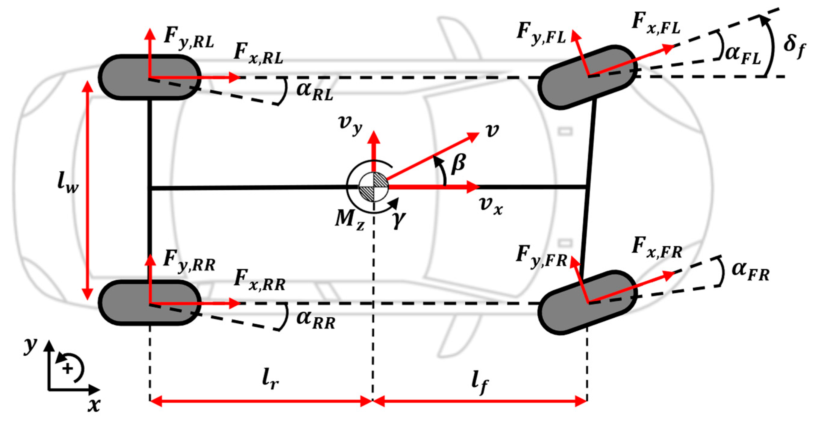
As illustrated in Figure 1, Newton’s second law is applied in a coordinate system attached to the vehicle’s center of gravity (CG) to derive the equations of motion governing lateral forces [37].
m v ˙ y + v x γ = F y f + F y r I z z γ ˙ = l f   F y f l r   F y r ,
where m   is the vehicle mass, I z z denotes the yaw moment of inertia, v x represents the longitudinal velocity, and γ signifies the yaw rate. Further, F y f and F y r denote the total lateral forces acting on the front and rear axles, respectively. The above yaw moment equation indicates that the vehicle’s rotational motion is generated solely by the lateral tire forces F y f and F y r   , which result from the front steering input δ f .   However, integrated chassis control systems enhance vehicle control authority by incorporating additional inputs beyond steering. Notably, DYC generates yaw moments by exploiting differences in driving or braking forces between the left and right wheels. Its defining feature is that it generates pure yaw moments solely by leveraging drive or brake force asymmetry, independent of lateral forces induced by the steering angle [38].
To accommodate additional control inputs, the yaw moment equation in the existing dynamic model must be augmented. The additional yaw moment generated by DYC is treated as a control input and introduced into the model as the term M z . This expansion enables the model to control the vehicle’s yaw motion independently of the steering input. Accordingly, the equations of motion incorporating DYC are expressed as follows [20]:
m v ˙ y   +   v x γ =   F y f   +   F y r I z z γ ˙   =   l f   F y f   l r   F y r + M z .
This expanded model forms the basis of a multiple-input system with two independent control inputs: the steering angle δ f and additional yaw moment M z .
The lateral forces generated by the tires are proportional to their respective slip angles. Under normal driving conditions, specifically, within the linear region where tire slip angles remain small, this relationship can be approximated as follows [39]:
F y f   =   2 C f α f ,     F y r   =   2 C r α r ,
where C f and C r denote the cornering stiffness of the front and rear axles, respectively, while the front- and rear-tire slip angles, α f and α r , are derived from the vehicle’s kinematic relationships:
α f   = δ f   β     l f γ v x α r   =   β   +   l r γ v x ,
where l f and l r represent the distances from the vehicle’s CG to the front and rear axles, respectively.
A state-space model is then constructed by combining the previously derived lateral dynamics of the vehicle with its position in the global coordinate system. By linearizing ψ   and β in the global coordinate frame, the vehicle’s heading angle ψ and lateral position y are expressed as follows:
ψ ˙ = γ , y ˙ = v x sin ψ + v y cos ψ v x ψ + β .
Combining Equations (2) and (5) yields the following state-space representation:
x ˙ p = A p x p + B p u ,
where the state vector is defined as x = y ,   β ,   ψ ,   γ T , the control input vector is defined as u = M z ,   δ f T and the system matrix A p R 4 × 4 , control matrix B p R 4 × 2 . Accordingly, the final lateral control state equation becomes:
d d t y β ψ γ = 0 v x v x 0 0 2 C f + C r m v x 0 1 2 l f C f l r C r m v x 2 0 0 0 1 0 2 l f C f l r C r I z z 0 2 l f 2 C f + l r 2 C r I z z v x A P y β ψ γ + 0 0 0 2 C f m v x 0 0 1 I z z 2 l f C f I z z B p M z δ f .
The state-space representation in Equation (7) is derived by linearizing the vehicle dynamics presented in Equation (2). Specifically, to obtain the state variable β ˙ , the approximation v ˙ y v x β ˙ was used. This approximation requires the assumption that the longitudinal velocity v x is constant. Also, this assumption is necessary to formulate the Linear Time-Invariant (LTI) structure of matrices A p R 4 × 4 and B p R 4 × 2 , which is required for the LQR and MRAC design.
However, in real-world driving scenarios, this assumed constant v x varies. This variation from the nominal LTI assumption is one of the factors contributing to model uncertainty. Additionally, parameters such as the cornering stiffness coefficients C f   and C r exhibit uncertainties that vary with road surface conditions and tire wear, leading to parameter variations and model uncertainties during real-world vehicle operation. Consequently, the control system must be sufficiently robust to accommodate such parameter variations and uncertainties.

2.2. Torque-Vectoring Model

While the 2-DOF model only accounts for the vehicle’s lateral motion and steering input, real vehicles can apply drive and brake forces independently to each of the left and right wheels, enabling direct yaw moment generation without relying on steering input [37]. By incorporating longitudinal wheel forces and individual wheel dynamics, which are not captured in the 2-DOF model, a 7-DOF vehicle model (Figure 2) is adopted. This model consists of three DOFs representing the vehicle body’s longitudinal, lateral, and yaw motions and four DOFs corresponding to the rotational dynamics of each wheel [40]. Consequently, the 7-DOF model enables torque vectoring by linking individual wheel torques and rotational dynamics to the vehicle-level longitudinal force and yaw moment.
m v ˙ x v y γ = F x f l + F x f r cos δ f F y f l + F y f r sin δ f + F x r l + F x r r , m v ˙ y + v x γ = F x f l + F x f r sin δ f + F y f l + F y f r cos δ f + F y r l + F y r r , I z z   γ ˙ = l f F x f l + F x f r sin δ f + F y f l + F y f r cos δ f l r F y r l + F y r r + l w 2 F x f r F x f l c o s δ f     + l w 2 F x r r F x r l + l w 2 F y f l F y f r s i n δ f ,
where m denotes the vehicle mass, I z z represents the yaw moment of inertia, v x and v y are the longitudinal and lateral velocities in the vehicle body coordinate system; and γ is the yaw rate. Additionally, l f and l r denote the distances from the vehicle’s CG to the front and rear axles, respectively, and l w represents the track width of the front and rear wheels. F x i j ,   F y i j represent the longitudinal and lateral forces generated at each wheel, where the wheel index i j f l , f r , r l , r r corresponds to front-left, front-right, rear-left, and rear-right, respectively.

3. MRAC

Autonomous vehicles must rely on advanced control systems capable of adapting to the diverse challenges encountered in real-world environments. As categorized in the Introduction, these challenges stem from a combination of (i) external disturbances, (ii) parameter variations, and (iii) modeling errors. The simplified 2-DOF model introduced previously is a prime example of such modeling errors, as it fails to capture the full complexity of real-world driving and relies on a fixed LTI assumption. This section explores how Model Reference Adaptive Control (MRAC) is specifically designed to address this gap by actively compensating for these combined uncertainties in real time and outlines an architectural framework for integrating adaptive control mechanisms into comprehensive chassis control systems.

3.1. Standard MRAC Framework

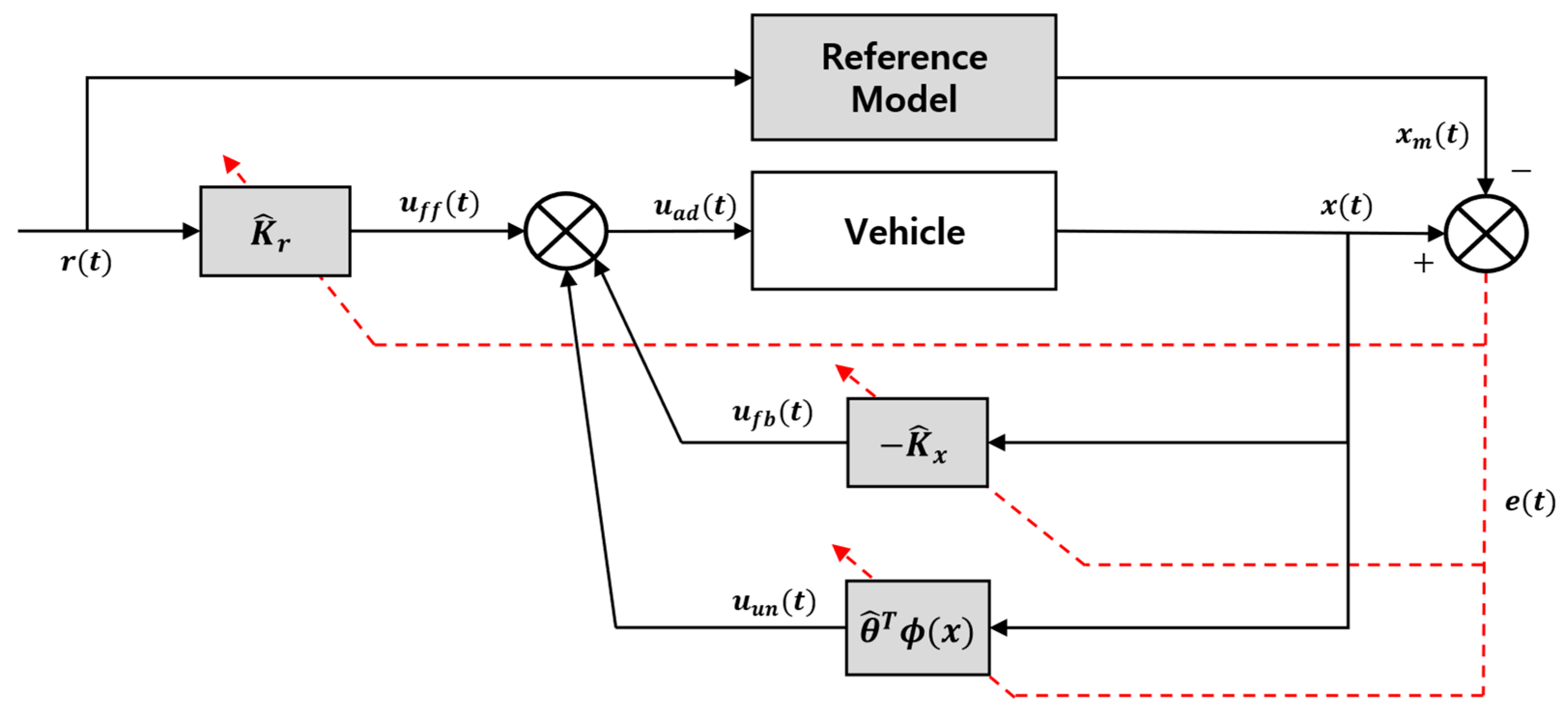
The objective of MRAC (Figure 3) is to design a feedback controller that allows the output of a system with uncertainties to continuously track a reference model with the desired dynamic characteristics [27].
A dynamic system that includes real-world uncertainties is defined as follows:
x ˙ p t = A p x p t + B p u t + Δ x p t ,
where x p t   R n denotes the vehicle’s state vector, u t   R m is the control input, and Δ x p t : R n R m represents the input-matched uncertainty. The uncertainty term in Equation (9) is assumed to be expressed in a linear parameter form:
Δ x p t = θ T ϕ t ,
where the basis function ϕ t :   R n R s and the unknown constant parameter matrix θ T   R m × s are defined as
ϕ t = ϕ 1 t , ϕ 2 t , , ϕ s t T .
Under the matched uncertainty assumption, system uncertainties affect the system only through the control input, allowing them to be canceled by the adaptive controller.
The ideal reference model that the system aims to track is defined as follows:
x ˙ m   t = A m x m t + B m r t ,
where the matrix A m satisfies the Hurwitz stability condition.
To achieve this objective, the matching condition given in Equation (13) is imposed. The state x p t of the actual system with uncertainties is required to asymptotically track the reference state x m t . This requires the matching conditions to be satisfied. Under this condition, constant gain matrices K x T R m ×   n and K r T R m ×   p exist such that, if the following equation is satisfied, the closed-loop dynamics of the actual system match those of the reference model in the ideal, uncertainty-free case:
A m = A p + B p K x T B m = B p K r T                       .
This confirms the existence of ideal control gains K x T   and K r T and indicates that exact model tracking is possible only if such ideal solutions exist. If the matching condition is satisfied, the structural differences between Equations (9) and (12) can be compensated through input gains, leaving only the parameter uncertainty θ T as the residual.
The MRAC law generates control input based on parameters estimated in real time. It comprises state feedback, reference signal feedforward, and uncertainty compensation components and is defined as
u a d t = K ^ x T x p t + K ^ r T r t θ ^ T ϕ t ,  
where K ^ x T   R m ×   n and K ^ r T R m ×   p are the estimated adaptive gains for the state and reference inputs, respectively, and θ ^ T R m × s is the estimated uncertainty parameter matrix. These parameters are initially assigned arbitrary values and updated in real time according to the adaptation law given in Equation (15). To ensure that the tracking error e ( t )   =   x p ( t )     x m ( t ) converges to zero as t   while maintaining bounded closed-loop signals, the following adaptation law is applied.
K ^ ˙ x t = Γ x x p t e T t P B p K ^ ˙ r t = Γ r r t e T t P B p , θ ^ ˙ t = Γ θ ϕ x p ( t ) e T t P B p            
where Γ x R n ×   n ,   Γ r R p ×   p ,   and   Γ θ R s ×   s are positive definite matrices corresponding to the state, reference input, and uncertainty parameters, respectively. According to the matching condition in Equation (13), ideal gains K x T   a n d   K r T exist. Assuming that the uncertainty parameter θ T is constant, the estimation errors are defined as K ~ x = K ^ x K x ,   K ~ r = K ^ r K r ,   θ ~ = θ ^ θ . By substituting the control input from Equation (14) into the system model expressed in Equation (9) and comparing it with the reference model in Equation (12), the tracking error dynamics are derived as
e ˙ t = A m e t + B p K ~ x T x p t + K ~ r T r t θ ~ T ϕ t .
Because matrix A m is Hurwitz, for any positive definite matrix Q > 0 , there exists a unique symmetric positive definite matrix P R n ×   n satisfying the Lyapunov equation:
A m T P + P A m = Q .
Based on this result, the Lyapunov function candidate is constructed as
V t = e T t P e t + t r a c e K ~ x T t Γ x 1 K ~ x t + t r a c e K ~ r T t Γ r 1 K ~ r t + t r a c e θ ~ T t Γ θ 1 θ ~ t .
After differentiating V ( t ) as defined in Equation (18) and substituting the error dynamics from Equation (16), the resulting derivative V ˙ ( t ) includes cross terms that couple the tracking error with the parameter-estimation errors. Applying the adaptation laws in Equation (15) and utilizing the cyclic property of the trace eliminates these parameter-dependent terms, ensuring that no contributions involving K ~ x , K ~ r , or θ ~ remain. Here, the matching condition in Equation (13) simply serves to express the dynamics in terms of estimation errors. Invoking the Lyapunov equation (Equation (17)) then yields:
V ˙ t = e T ( t ) Q e ( t ) .
Because Q is positive definite, Equation (19) implies that V t is non-increasing; consequently, the tracking error e and the parameter estimation errors remain bounded. Moreover, if the reference r ( t ) and regressor ϕ t are both bounded and A m and B m are constants, then Equation (16) ensures that e ˙ t is also bounded; consequently, e T ( t )   Q   e ( t ) becomes integrable and uniformly continuous. By Barbalat’s lemma, e t 0 as t ; that is, the system asymptotically tracks the reference-model state [41].
However, when standard MRAC is applied to vehicle systems, high adaptation rates induce chattering and drift in the parameter estimates, thereby degrading both the stability of the control input and overall vehicle controllability [28]. From the actuator’s perspective, elevated adaptation rates generate high-frequency oscillations in the control signal, exacerbating actuator saturation and mechanical wear. These effects, in turn, diminish control-tracking performance. In addition, excessive control-signal oscillations undermine overall system stability. The leakage term in Equation (20) helps to suppress parameter chattering and drift at high adaptation rates, thereby attenuating rapid variations in control inputs and reducing actuator vibration and flutter. This capability is essential for enabling autonomous vehicles to maintain robust control performance across diverse driving conditions. Therefore, a mechanism that ensures stable updating of MRAC laws is needed.

3.2. σ-Modification

The σ -modification strategy improves controller robustness by preventing parameter drift under disturbances or model uncertainties and by partially suppressing instability induced by excessively rapid adaptation [42]. It introduces a small leakage (damping) term into the adaptive control law, which suppresses rapid parameter variation, strengthens robustness, and alleviates instability resulting from excessive adaptation. This modification introduces a trade-off, often balanced against the adaptation gain Γ discussed in Section 3.1. Increasing the leakage term σ effectively dampens parameter vibration and reduces control chattering caused by high adaptation rate.
Accordingly, applying σ-modification to the adaptation law in Equation (15) yields the following formulation:
K ^ ˙ x t = Γ x x p t e T t P B p σ x K ^ x t K ^ ˙ r t = Γ r r t e T t P B p σ r K ^ r t θ ^ ˙ t = Γ θ ϕ x p ( t ) e T t P B p σ θ θ ^ t ,
where σ x ,   σ r ,   a n d   σ θ are positive scalar leakage gains. To demonstrate Lyapunov stability under σ -modification, we first time-differentiate Equation (18) and the error dynamics in Equation (16) and then apply the Lyapunov equation (Equation (17)) to obtain the following:
V ˙ t = e T t Q e t + 2 t r a c e K ~ x T Γ x 1 K ~ ˙ x + 2 t r a c e K ~ r T Γ r 1 K ~ ˙ r + 2 t r a c e θ ~ T Γ θ 1 θ ~ ˙ + 2 t r a c e K ~ x T x p t e T t P   B p + 2 t r a c e K ~ r T r t e T t P   B p 2 t r a c e θ ~ T ϕ t e T t P   B p .
By substituting the updated adaptation laws from Equation (20) for K ~ ˙ x ,   K ~ ˙ r ,   a n d   θ ~ ˙ , we obtain
2 t r a c e ( K ~ x T Γ x 1 K ~ ˙ x ) = 2 t r a c e K ~ x T x p t e T t P B p 2 σ x t r a c e K ~ x T Γ x 1 K ^ x 2 t r a c e ( K ~ r T Γ r 1 K ~ ˙ r ) = 2 t r a c e K ~ r T r t e T t P B p 2 σ r t r a c e K ~ r T Γ r 1 K ^ r 2 t r a c e ( θ ~ T Γ θ 1 θ ~ ˙ ) = 2 t r a c e θ ~ T ϕ t e T t P B p 2 σ θ t r a c e θ ~ T Γ θ 1 θ ^ .
The cross-term 2 e T P B p ( ) in Equation (21) cancels with the first terms in Equation (22) owing to the cyclic property of the trace. Moreover, the A m -related term from Equation (17) is expressed as e T ( t ) Q e ( t ) , yielding
V ˙ t = e T t Q e t 2 σ x t r a c e K ~ x T Γ x 1 K ^ x 2 σ r t r a c e K ~ r T Γ r 1 K ^ r 2 σ θ t r a c e θ ~ T Γ θ 1 θ ^ .
Equation (23) indicates that σ -modification introduces parameter damping terms with negative signs into the error term e T ( t ) Q e ( t ) . Substituting K ^ x = K ~ x + K x ,   K ^ r = K ~ r + K r ,   θ ^ =   θ ~ + θ and applying Young’s inequality to Equation (23) yield
V ˙ t e T Q e σ x K ~ x Γ x 1 2 σ r K ~ r Γ r 1 2 σ θ θ ~ Γ θ 1 2 + c σ ,
where X Γ 1 2 = t r a c e X T Γ 1 X and c σ = σ x K x Γ x 1 2 + σ r K r Γ r 1 2 + σ θ θ Γ θ 1 2 .
Because Equations (17) and (18) imply that V is positive definite, there exists α > 0 such that V ˙ t α V + c σ ; consequently, V t   e α t V ( 0 ) + c σ / α , ensuring that all closed-loop signals remain uniformly ultimately bounded [29]. Increasing the leakage term effectively dampens parameter vibration and reduces the control’s high-frequency oscillations often caused by a high adaptation rate. However, as the UUB proof demonstrates, the ultimate bound V   c σ / α is dependent on c σ and α . This implies that the tracking error converges to non-zero residual set. This convergence to a bounded region provides robustness by preventing the unbounded growth of adaptive gains in the presence of such disturbances, thereby guaranteeing a bounded tracking error despite unmodeled dynamics or disturbances not aligned with the control input channel. Consequently, σ-modification slows and damps adaptation to avoid chattering and actuator stress, at the cost of converging to a small residual error instead of zero. The selection of the leakage term should balance adaptation speed against the magnitude of the ultimate bound.

4. Design of the Proposed Adaptive Integrated Chassis Controller

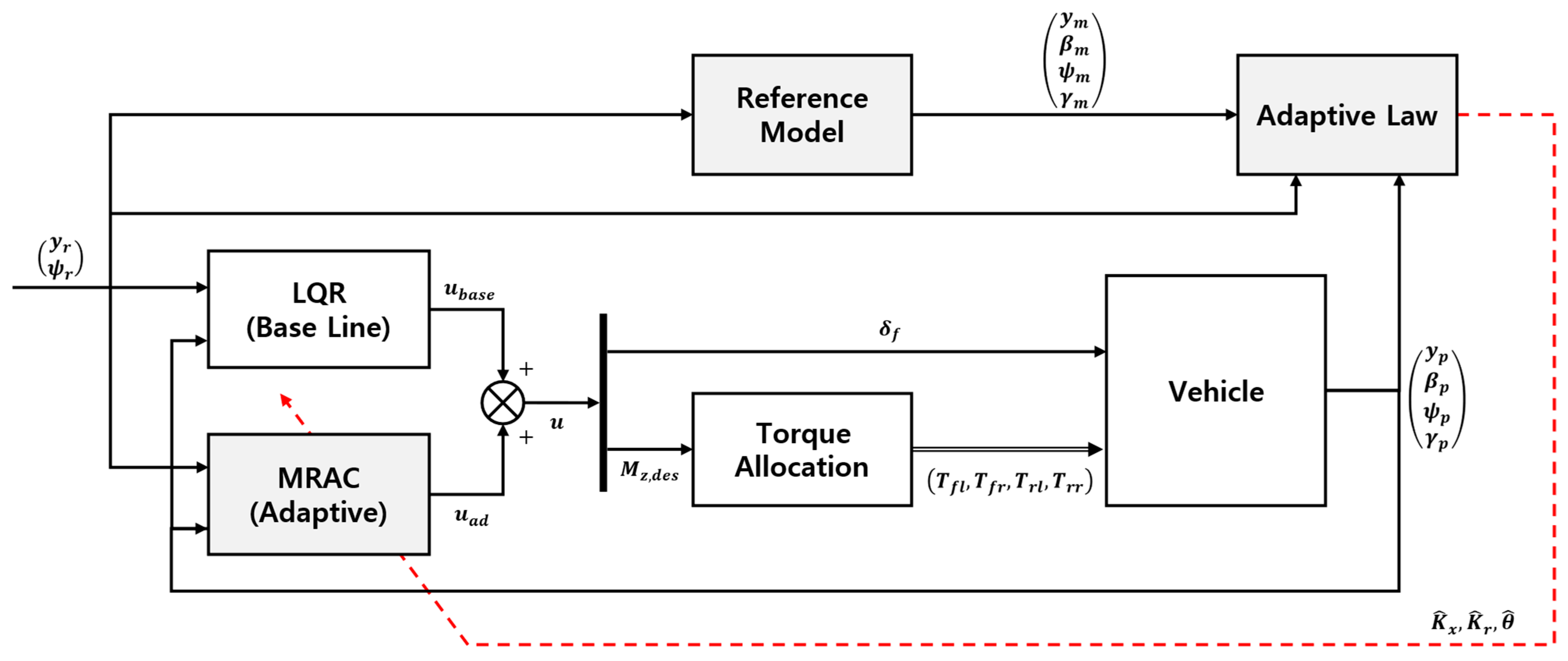
Figure 4 presents the configuration of the proposed adaptive integrated chassis control architecture, which consists of two layers: an upper control layer and a lower allocation layer [43]. Specifically, in the upper layer, a linear quadratic regulator (LQR) generates the nominal steering angle δ f and direct yaw moment M z , d e s [44], while an MRAC framework, driven by the tracking error relative to a reference model that reproduces the LQR closed-loop behavior, provides adaptive compensation. Under ideal driving conditions, the LQR governs the response. However, as parameter variations or external disturbances increase, the MRAC engages to preserve tracking accuracy and stability margins. The lower layer reformulates the desired M z , d e s and longitudinal force demand as a constrained weighted least-squares problem, mapping the optimized solution to the four in-wheel motor torques [45]. Furthermore, by feeding vehicle states back into both command generation and the adaptive law, the system ensures consistent path tracking and robust attitude stability across diverse conditions.
In the proposed hierarchy, the outer loop computes nominal commands from geometric outputs ( y ,   ψ ), while the inner vehicle dynamics evolve through the sideslip ( β ) and yaw rate ( γ ). In real driving scenarios, practically mismatched disturbances such as crosswinds and asymmetric road friction generate unintended lateral forces and yaw moments that alter the internal states ( β ,   γ ), which can leave the inner channels weakly damped when steering alone is used. By directly injecting yaw acceleration via DYC, the relative degree of the yaw channel is effectively reduced, and additional control authority is granted over ( β ,   γ ); hence, shaping the inner dynamics explicitly supports robust outer-loop tracking under severe operating conditions.

4.1. Design of the Lateral Controller

To achieve consistent lateral control effectiveness across diverse driving situations, the proposed integrated chassis control architecture (Figure 4) incorporates a nominal controller formulated on LQR principles alongside an adaptive compensator based on MRAC [46]. The primary LQR controller simultaneously computes control commands for the vehicle’s steering angle δ f and direct yaw moment M z , d e s , while the MRAC component estimates and mitigates model uncertainties and environmental perturbations in real time [30]. Although the LQR controller is designed to ensure stability and maintain robust characteristics, its tracking performance can be degraded by variations in system parameters or external disturbances. In response, the MRAC component functions in coordination with the LQR controller to enhance the overall stability margin of the system [35]. In summary, under nominal operating conditions, the LQR controller ensures optimal path-tracking performance, whereas in the presence of model mismatch, the MRAC framework provides additional compensation, thereby improving both stability and tracking accuracy.
The lateral controller is designed using a state-space representation based on the vehicle model derived in Section 2. The vehicle lateral dynamics model represented in equation (7) is expressed in the state-space form. The state vector is x = y ,   β ,   ψ ,   γ T ,   and the control input vector is u b = M z , d e s ,   δ f T . The LQR nominal controller for path-tracking is formulated based on the full state vector x p ( t ) and the reference input r ( t ) .
The LQR control law is
u b = K x x p t + K r r ( t ) .
Here, r ( t ) denotes the target value, y r ,   ψ r T   R 2 , from the reference path. The 2 × 4 optimal state feedback gain matrix K x is designed to minimize the following cost function [47]:
J = 0 x p t T Q x p t + u t T R u t d t .
This optimization problem is solved analytically using the algebraic Riccati equation shown in Equation (27). After obtaining the solution P to this Riccati equation, the optimal feedback gain matrix is computed as follows [47]:
A p T P + P A p P B p R 1 B p T P + Q = 0 ,
K x = R 1 B p T P .
The 2 × 2 feedforward gain matrix K r is synthesized to provide physically intuitive feedforward action. This is achieved by utilizing the gain components from K x to directly align the reference inputs ( y r ,   ψ r ) with the feedback channels of their corresponding states ( y ,   ψ ) . To enhance system robustness, the MRAC framework is integrated as an adaptive augmentation to the upper controller. The MRAC reference model is configured to track the behavior of the closed-loop system with the LQR controller. Specifically, the reference model matrices incorporate the effect of LQR state feedback on the nominal vehicle model.
The MRAC reference model is defined based on the closed-loop configuration of the LQR controller:
A m = A p B p K x B m = B p K r                     .
The configuration in Equation (29) captures the closed-loop dynamic characteristics of the nominal LQR controller. Under ideal conditions, the vehicle system follows the behavior of this reference model, while MRAC applies compensatory control to ensure that the actual vehicle accurately tracks it. However, if the actual operating conditions deviate significantly from the nominal assumptions—particularly due to velocity variations that violate the LTI assumption in Equation (7), or parameter variations in mass and cornering stiffness—a mismatch arises between the reference model and actual system behavior, requiring the MRAC to provide larger compensatory inputs. Furthermore, when operating beyond the design conditions, the increasing control input demanded by the MRAC controller can lead to instability.
In this research, the regressor function ( ϕ ( t ) ) is defined using only the control and disturbance channels of the 2-DOF bicycle model augmented with DYC (Equation (7)). With the state vector x p = y ,   β ,   ψ ,   γ T , practically mismatched disturbances that manifest as unintended lateral-force and yaw-moment components are modeled by d = F y , d ,   M z , d T through.
B d = 0 0 1 m v x 0 0 0 0 1 I z z R 4 × 2 ,
so that F y , d and M z , d act in β ˙ and γ ˙ . To partially include and compensate mismatched disturbance components without explicit disturbance estimation, projection operators built from the control and disturbance channels are employed, using B p R 4 × 2 from Equation (7).
ϕ t = G e t ,     G B p + B d B d + R 2 × 4 ,
where e = x p x m collects the tracking errors with respect to the closed-loop reference model in (29) and ( · ) + denotes the Moore–Penrose pseudoinverse. The regressor satisfies a disturbance-aligned scaling operator that maps the component of e lying in the disturbance subspace Range B d into the controllable input subspace Range B p .
B p ϕ t = B p B p + B d B d + e = P B p ( P B d e ) ,
Consequently, Equation (32) acts as a projection that enhances the internal yaw–sideslip dynamics and mitigates the influence of external disturbances. More generally, even if modeling errors or operating-point drift lead to R a n g e B d R a n g e B p , the composite projector P B p ,   P B d retains only the controllable portion of the disturbance-aligned component of e ( t ) that lies in R a n g e ( B p ) , while the non-realizable remainder I P B p P B d e ( t ) is not reflected in the input. This partial projection demonstrates that partial compensation of the disturbance is achievable.
The overall control law for the adaptive integrated chassis control system is expressed as follows:
u t = u b t + u a d t .
Here, u b represents the basic control input from the LQR controller, while u a d denotes the adaptive control input generated by the MRAC framework. This adaptive augmentation structure integrates nominal control and adaptive compensation within a unified scheme, maintaining a balance between control performance and stability. From an operational standpoint, the basic LQR controller manages transient or overall conditions, thereby narrowing the range of parameter variations that the MRAC framework must adapt to and reducing the magnitude of continuous adaptation.
K ^ x T 0 = K x K ^ r T 0 = K r        
Furthermore, under initial operating conditions, the MRAC framework is designed to function similarly to the LQR controller, thereby ensuring a seamless transition between the two control strategies.
A traditional integrated chassis control system extends control capabilities by coordinating steering and direct yaw moment control, enabling effective responses in driving conditions that are difficult to manage with single-actuator control. However, its performance remains dependent on a predetermined model. In contrast, the integrated LQR + MRAC framework effectively addresses model uncertainties by dynamically adjusting controller parameters even in the presence of disturbances within an environment defined by augmented control capabilities. It sustains stability and tracking performance through adaptive control input modification in response to environmental variations.

4.2. Design of the Chassis Controller

The torque distribution strategy is formulated using a weighted least squares optimal cost function to accommodate the system’s over-actuated configuration (four in-wheel motors and two targets) [48].
J T = Ω W v B T v 2 2 + W u T 2 2
Here, T = T F L , T F R , T R L , T R R T   R 4 denotes the motor torque vector, the parameters for the cost function were selected to ensure robust tracking. The relative weighting factor Ω was set to 10. The error weighting matrix W v > 0 corresponds to the M z ,   F x T error weighting; in this study, W v = d i a g ( [ 20 ,   10 ] ) to place a higher priority on accurately tracking the desired yaw moment. Also, input weighting matrix W u > 0 is a diagonal matrix that is dynamically adjusted by W u = [ 8 / F z , F L , 8 / F z , F R , 4 / F z , R L , 4 / F z , R R ] .
The corresponding optimization problem is expressed as follows [49]:
T = argmin T J ( T )             s . t .     T T T + T + = min T ¯ ,   T k 1 +   Δ T m a x T = max T _ ,   T k 1 +   Δ T m i n .
Here, the static upper and lower bounds T ¯ ,   T _ are obtained from each motor’s torque–speed (T–N) map and T k 1 is the motor torque command from the previous control step. The dynamic bounds, Δ   T m a x (upper) and Δ   T m i n (lower), specify the per-wheel torque variations achievable within one control period under the torque rate constraint applied to the previous command. At each sampling instant, the admissible torque range [ T ,   T + ] for each wheel is determined through elementwise comparison between the dynamic limits and the static bounds.
The target vector combines the output of the upper lateral controller and longitudinal requirements such as:
v = M z , d e s F x R 2 .
The geometric equation relating torque, force, and moment is
B = 1 r e f f l f sin δ f l w 2 cos δ f l f sin δ f + l w 2 cos δ f l w 2 l w 2 cos δ f cos δ f 1 1 R 2 × 4 .
The control matrix B is constructed based on the front-wheel steering angle δ f , front–rear CG distance l f , front–rear track width l w , and effective radius r e f f . The influence of the torque vector T on the yaw moment and total longitudinal force is represented using a linear approximation.
The cost function is defined as a weighted sum of motor usage and tracking errors associated with the desired yaw moment and total longitudinal force. When the weights are positive definite, the objective becomes a convex quadratic program (QP). Elementwise box constraints preserve the convexity of the feasible set, ensuring a global optimum for the torque allocation QP under strictly positive definite weights and feasibility. Given this convexity, the optimization problem is solved numerically at each control timestep. This study implemented the allocator in Simulink using the active-set algorithm, operating at a sampling rate of 100 Hz. In this study, the front and rear axles are equipped with motors rated at 650 Nm and 1500 Nm, respectively, with corresponding torque rate limits of 1250 Nm/s and 5000 Nm/s.

5. Simulation and Results

5.1. Simulation Setup

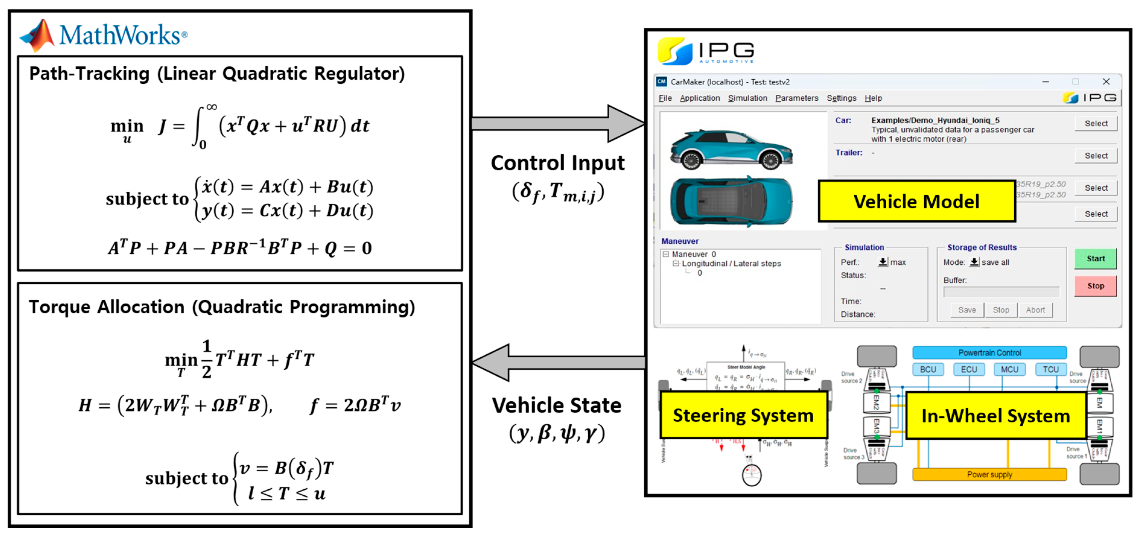
To evaluate the performance of the proposed Adaptive integrated chassis controller, co-simulations were performed using CarMaker 12.0.1 integrated with MATLAB/Simulink R2022b. The test vehicle was configured based on the Hyundai IONIQ 5 baseline model in CarMaker, modified with four independent in-wheel motors to enable torque vectoring. Vehicle dynamics were modeled using CarMaker’s built-in modules, while control algorithms were implemented in Simulink and executed via real-time co-simulation, as illustrated in Figure 5.
The lateral model parameters used in this study are summarized in Table 1.
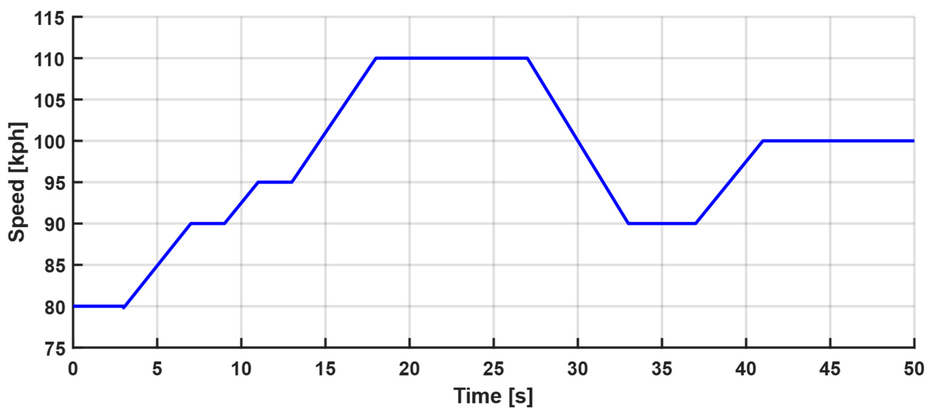
The reference trajectory, shown in Figure 6, was designed to simulate demanding conditions, such as collision avoidance, by incorporating multiple abrupt lane changes that require lateral accelerations a y up to 0.8 g. The vehicle velocity profile, as shown in Figure 7, was configured to vary between 80 and 110 kph. At lower speeds, vehicle behavior is largely governed by kinematics, and the dynamic uncertainties (such as parameter variations and modeling mismatch) that the proposed MRAC controller targets have a negligible effect. In contrast, the 80–110 kph range used in this study is a region where vehicle dynamics exert a dominant influence.
Four scenarios were developed to systematically evaluate the controller’s robustness against the key uncertainty categories identified in the Introduction, as detailed in Table 2.
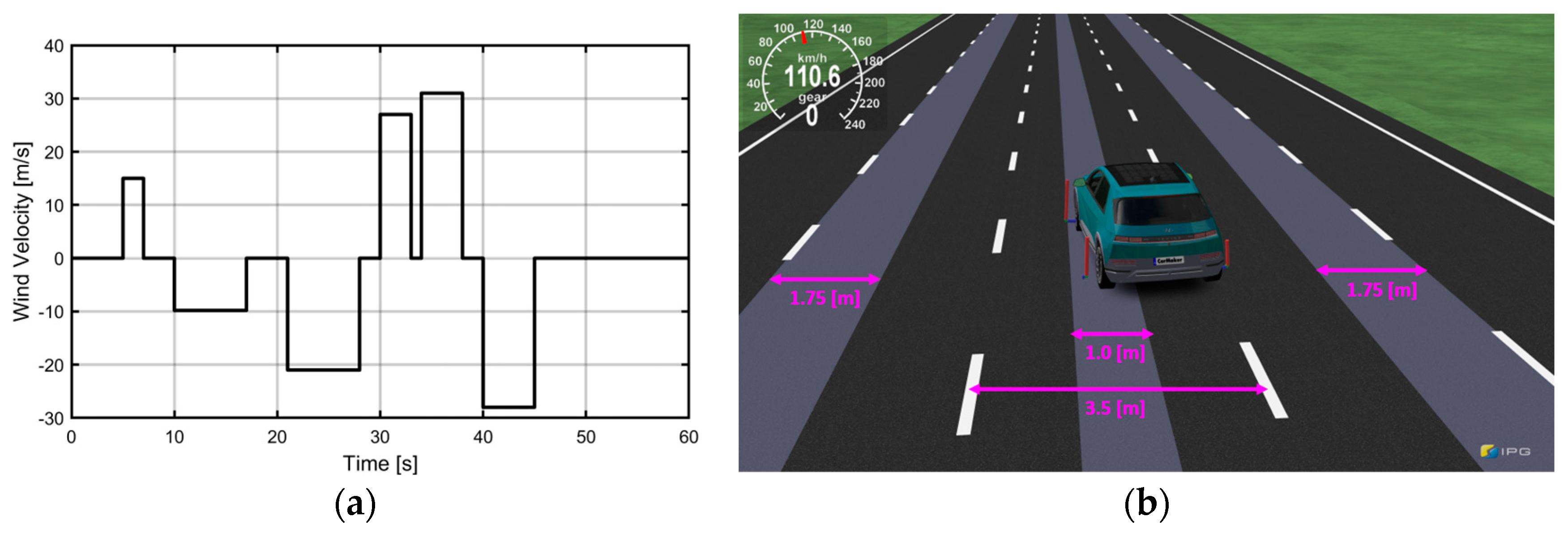
First, External Disturbances were introduced. Scenarios 2 and 4 include Cross Winds (Figure 8a), which generate additive lateral aerodynamic forces opposing vehicle motion. The crosswind magnitude varies between 15 and 30 m/s.
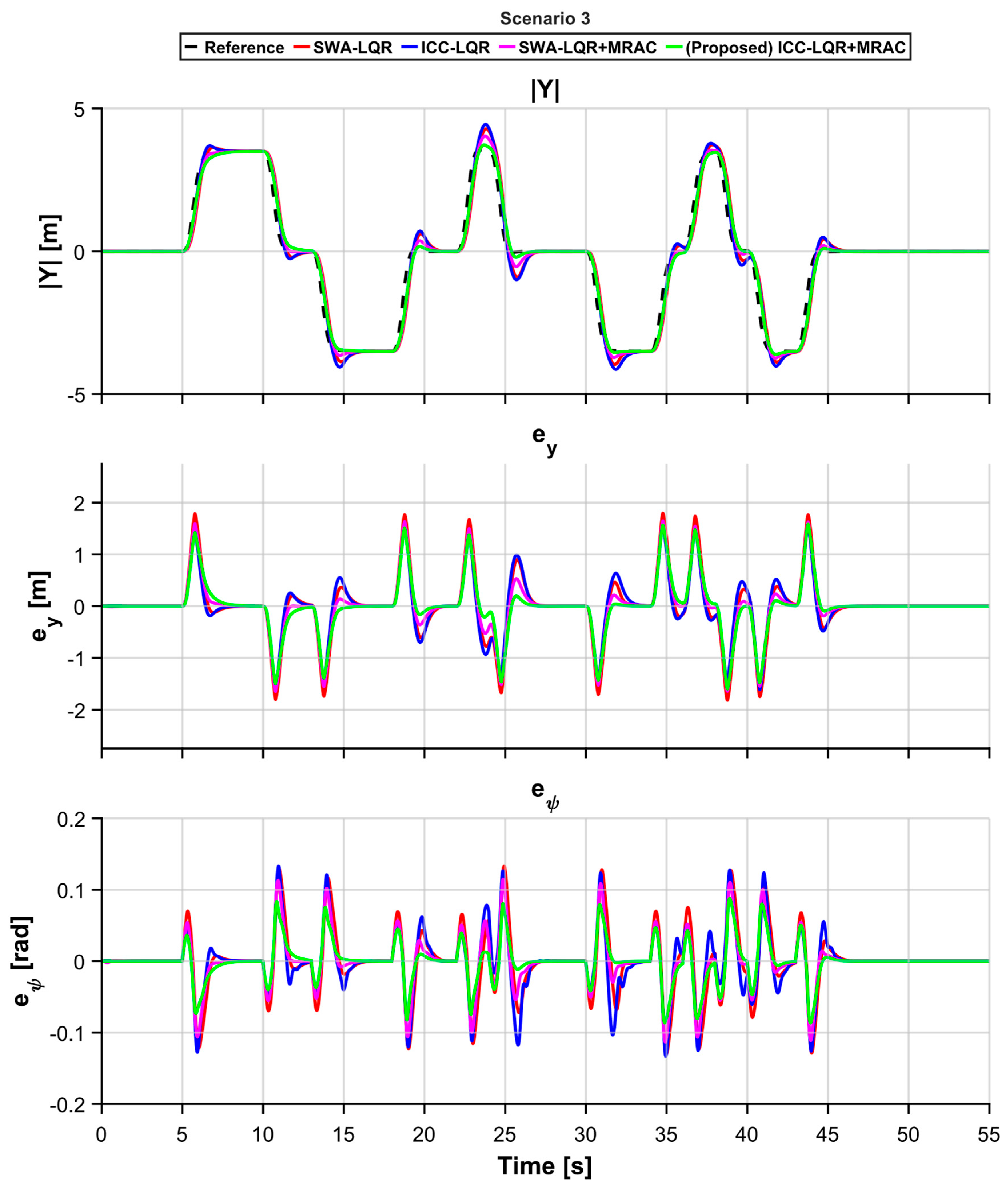
Second, Parameter Variations were simulated. Scenarios 3 and 4 introduce split-μ Road Friction (Figure 8b), representing sudden variations in tire-road parameters. These sections feature wet road ( μ = 0.4 ) and dry-road ( μ = 0.8 ) conditions, which alter the tire cornering stiffness ( C f ,   C r ) and increase the likelihood of vehicle slip.
Finally, all scenarios include a +180 kg mass increase to represent parameter variations in m and I z z . In addition, each scenario is executed under an 80–110 kph velocity profile that, while reflecting drift in v x , explicitly violates the constant velocity assumption used to derive the LTI model, thereby introducing modeling mismatch.
The initial parameters of the MRAC framework were derived from the LQR control gains to ensure that the MRAC framework was initiated with the closed-loop dynamics of the LQR controller. The final tuned values in Table 3 were derived from simulations guided by the trade-offs discussed in Section 3.2. These parameters were set to ensure robust path-tracking stability across all scenarios (1–4), while specifically for high-disturbance conditions like Scenario 4, preventing severe chattering and permitting only mild, acceptable transient oscillations. This tuning satisfies the practical requirement for smooth actuator operation while ensuring high tracking accuracy and stability. Furthermore, because the torque vectoring system exhibits faster response characteristics than the steering system, relatively higher adaptive gains were assigned to the torque vectoring control through the in-wheel motors.

5.2. Results

This section presents an evaluation of the path-tracking accuracy and vehicle stability of the proposed integrated chassis controller under various driving conditions and external disturbances. Four control configurations are compared: steering-only control—SWA-LQR (conventional LQR) and SWA-LQR+MRAC (LQR+MRAC-enhanced steering control)—and integrated chassis control with steering and torque vectoring—ICC-LQR (integrated chassis LQR) and ICC-LQR+MRAC (proposed LQR+MRAC-based integrated control).
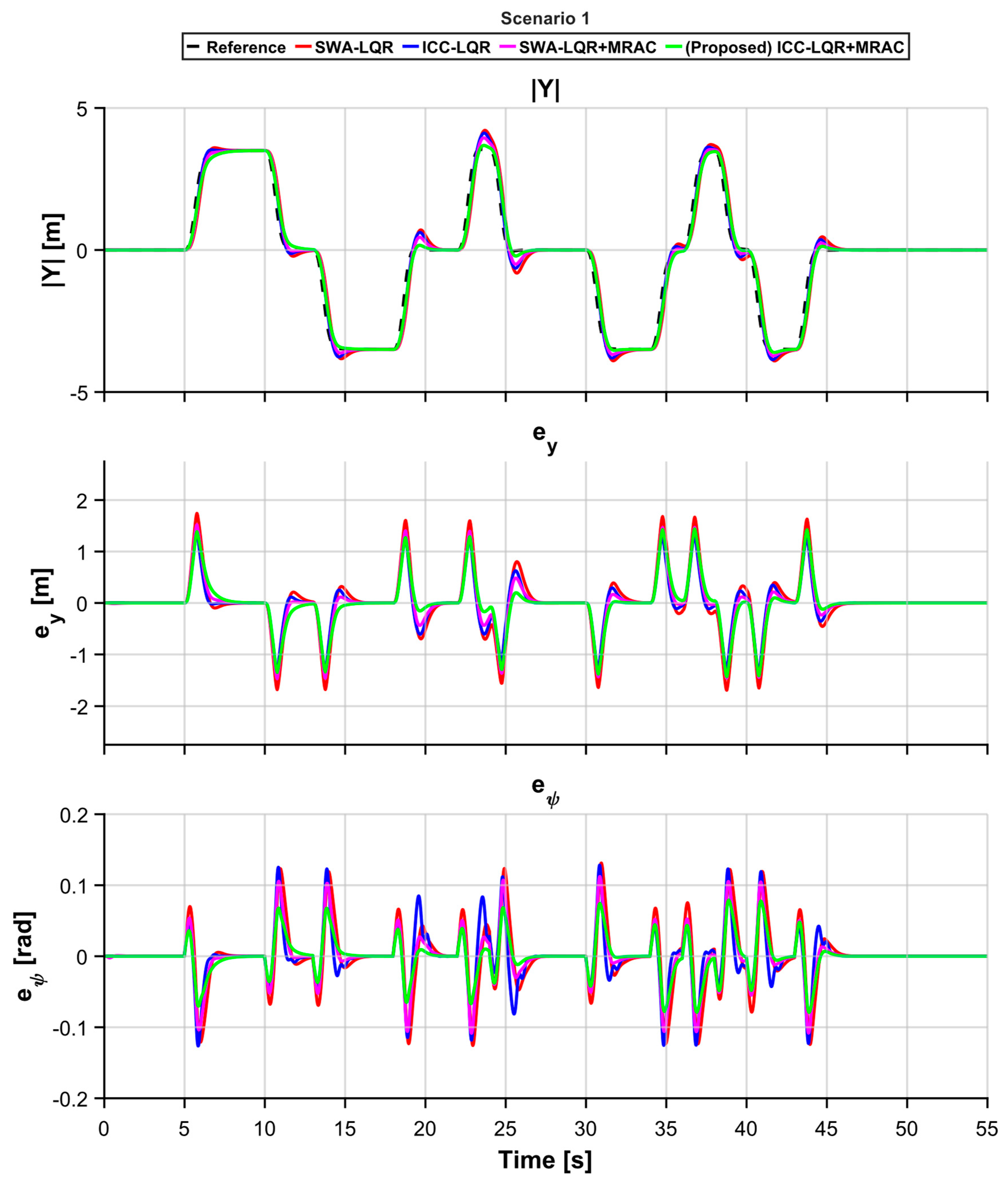
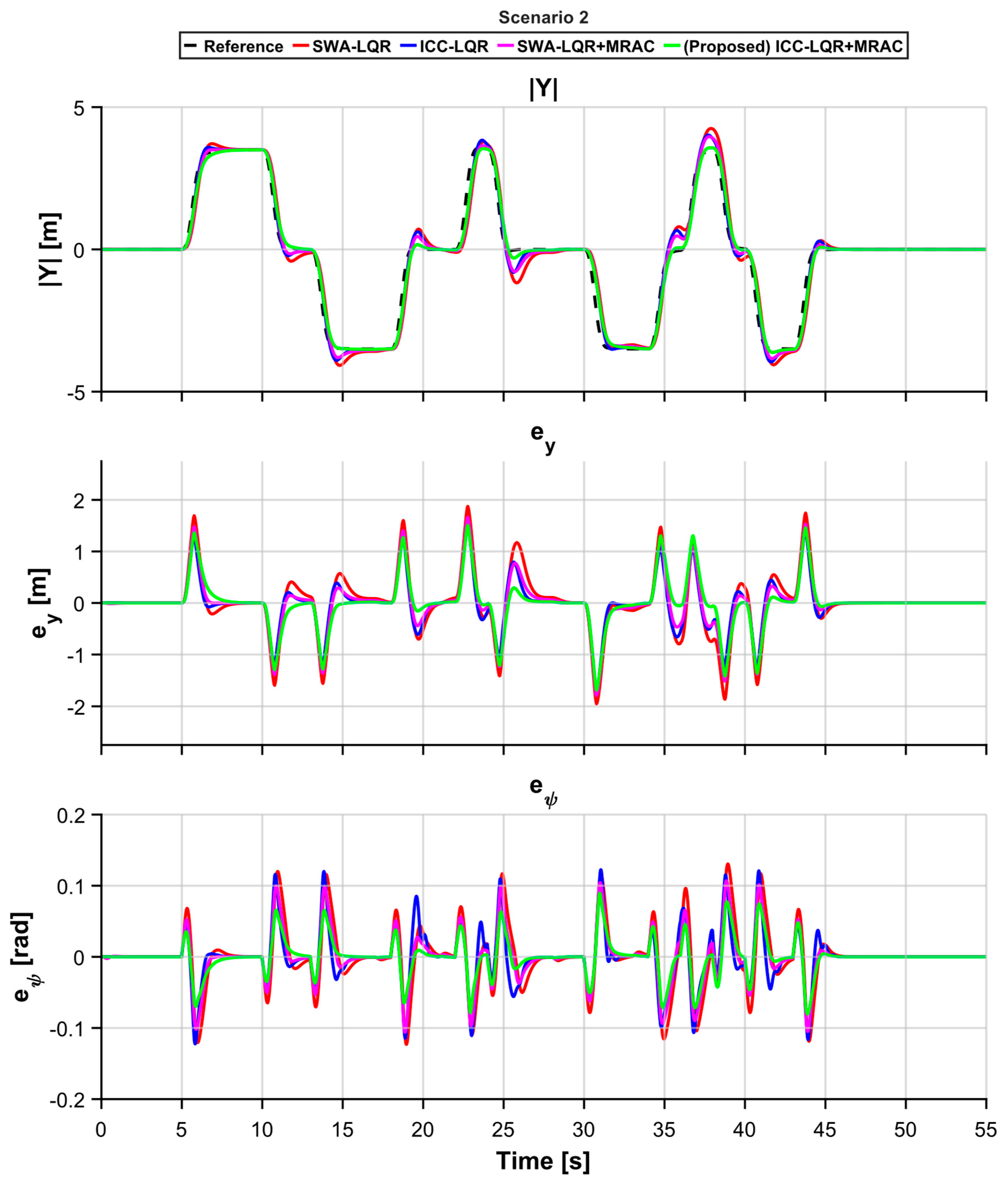
The control performance evaluations are based on the results presented in Figure 9, Figure 10, Figure 11 and Figure 12, which illustrate the lateral position ( y ), lateral tracking error relative to the reference trajectory ( e y ) and heading error relative to the reference trajectory ( e ψ ) . These results enable assessment of how effectively each control configuration maintains the desired path and vehicle stability under progressively severe disturbances, thereby demonstrating the performance advantages of the proposed ICC-LQR+MRAC strategy.
In Scenario 1, the path-tracking performance of each controller was evaluated under increased vehicle mass, as depicted in Figure 9. All four controllers produced small tracking errors, and no notable stability issues were observed. Specifically, for SWA-LQR, the vehicle followed the reference trajectory; however, parameter variations due to speed changes introduced a mismatch between the nominal and actual vehicle models, resulting in a slight response delay and increased tracking error. In contrast, the ICC-LQR controller, which combines steering with torque vectoring, demonstrated improved stability over steering-only LQR due to its additional direct yaw moment control. The SWA-LQR+MRAC controller, by adapting to the increased vehicle mass, achieved smaller errors than its non-adaptive counterpart. Notably, the proposed ICC-LQR+MRAC controller, integrating adaptive and chassis control, achieved the smallest lateral deviation and delivered the highest tracking accuracy and stability among all configurations.
In Scenario 2, path-tracking performance was evaluated under increased vehicle mass and a strong crosswind disturbance, as depicted in Figure 10. Under these conditions, SWA-LQR exhibited limited capacity to resist the persistent crosswind, causing the vehicle to drift downwind. Consequently, lateral deviation reached approximately 0.85 m, with notable increases in both path and heading errors. Meanwhile, SWA-LQR+MRAC adapted to the crosswind through real-time MRAC-based gain adjustment; however, it could not fully counter the wind-induced lateral force, yielding performance comparable to that of ICC-LQR. In ICC-LQR, the integrated control directly compensated for the wind-induced lateral deviation through yaw moment generation, thereby controlling the vehicle’s attitude more effectively and maintaining smaller tracking errors than the steering-only controllers. In contrast, the proposed control system adaptively compensated for the crosswind in real time and cooperatively employed steering and torque vectoring, thereby achieving the most effective suppression of crosswind-induced path deviation.
In Scenario 3, controller performance was examined under split-μ conditions, representing partial road surface friction reduction (Figure 11). When the vehicle entered the low-friction road section, the SWA-LQR controller struggled to maintain the reference trajectory owing to reduced tire–road grip, which limited lateral force generation and induced temporary path deviations and instability. The SWA-LQR+MRAC configuration showed partially improved trajectory maintenance by adjusting its control parameters through adaptive control. However, the ICC-LQR controller, which generates a fixed yaw moment and distributes it to the wheel torques, exhibited increased lateral deviation when the tire friction limit was exceeded in the low-friction section, resulting in wheel slip. This occurred because torque distribution depends on tire friction utilization and is affected by changes in road conditions. The proposed controller combined adaptive control with integrated control to compensate for variations in the vehicle’s dynamics caused by sudden changes in road surface friction. Consequently, the vehicle was able to traverse the slippery section with minimal path deviation, and in Scenario 3, the proposed system achieved the smallest path-tracking error.
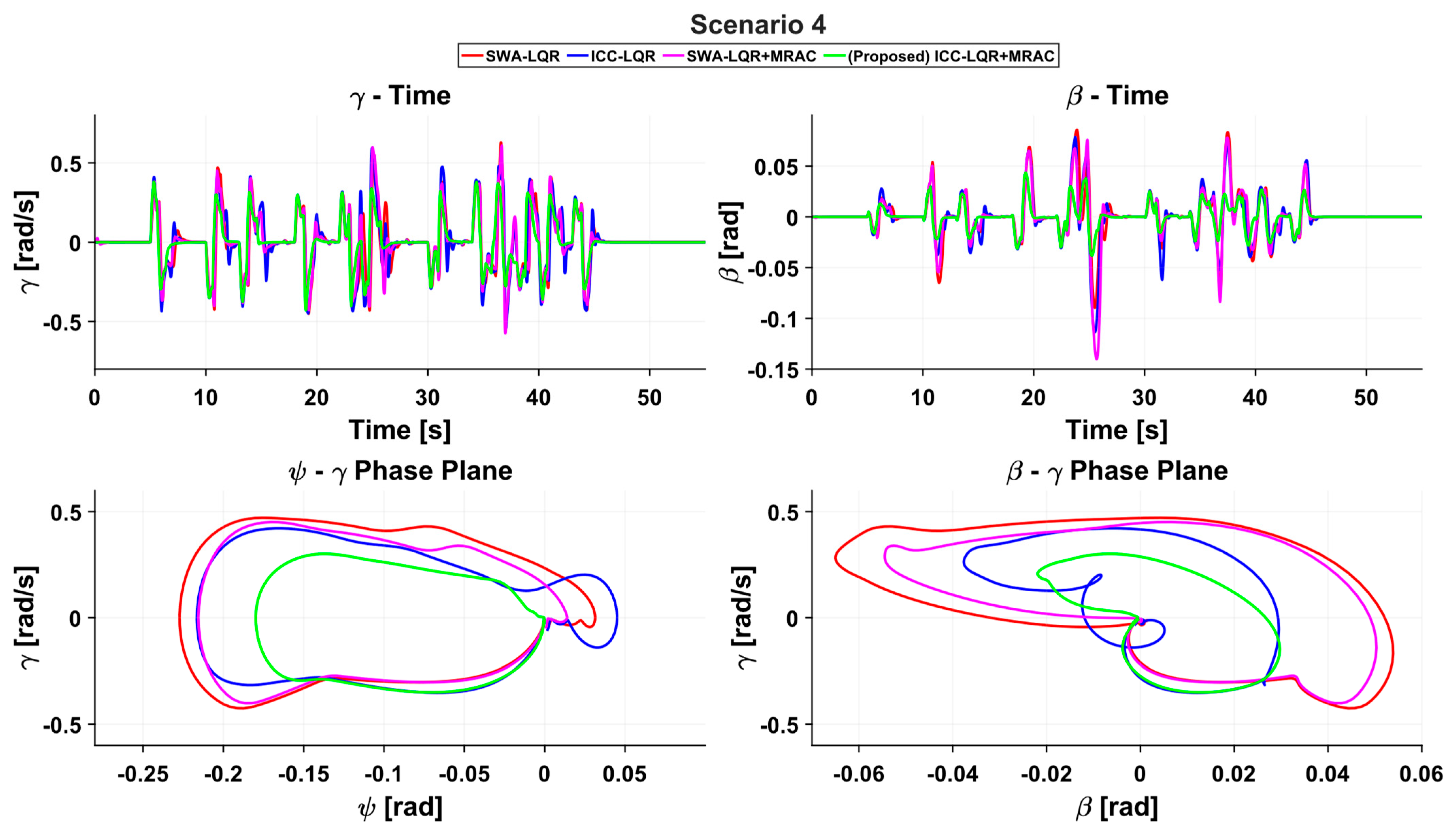
In Scenario 4, the robustness of each controller was comprehensively tested under the most severe driving conditions, where increased vehicle mass, strong crosswinds, and reduced road friction acted concurrently (Figure 12). For SWA-LQR, the abovementioned limitations resulted in severe path deviation. When the vehicle was subjected to strong crosswinds and experienced slippage, steering control alone failed to stabilize its attitude, and the lateral deviation increased markedly to 1.25 m. With SWA-LQR+MRAC, large tracking errors persisted between 30 and 45 s, during which the crosswind intensity reached 30 m/s. For ICC-LQR, tracking performance degraded under the combined disturbances. Particularly, in certain segments near 15 s, it underperformed relative to SWA-LQR. In contrast, the proposed controller (ICC-LQR+MRAC) employed adaptive control mechanisms to suppress crosswind-induced bias and, while responding to vehicle dynamics on the low-friction section, adjusted steering and torque vectoring commands in a coordinated manner. Consequently, even in the harsh conditions of Scenario 4, ICC-LQR+MRAC maintained accurate path tracking with markedly lower error than the other controllers while ensuring stable attitude control.
Beyond these results, additional analyses of internal dynamics and phase-plane plots clearly demonstrate how ICC-LQR+MRAC sustains both stability margins and tracking accuracy under the combined disturbances of Scenario 4.
As illustrated in Figure 13, MRAC, driven by a closed-loop reference model, generates the ideal internal-dynamic states ( β m ) and ( γ m ) and forces the plant states ( β p ,   γ p ) to follow them, thereby securing lateral stability; this stability is further ensured by coordinating DYC-based yaw-moment control with steering control. In the time histories of ( β ( t ) ) and ( γ ( t ) ), steering-only configurations exhibit large peaks and slow decay on entering the low-friction segment or when the crosswind grows to 30 m/s ( 30–45 s), whereas the proposed controller suppresses the simultaneous peaks and shortens the resettling interval after the worst gusts, indicating well-damped internal dynamics despite disturbance.
Also, the phase-plane plots in Figure 13 corroborate this: during the rapid lane-change transient at 10–13 s, the proposed controller yields the smallest loop area and fastest contraction toward the origin, demonstrating enhanced stability performance.
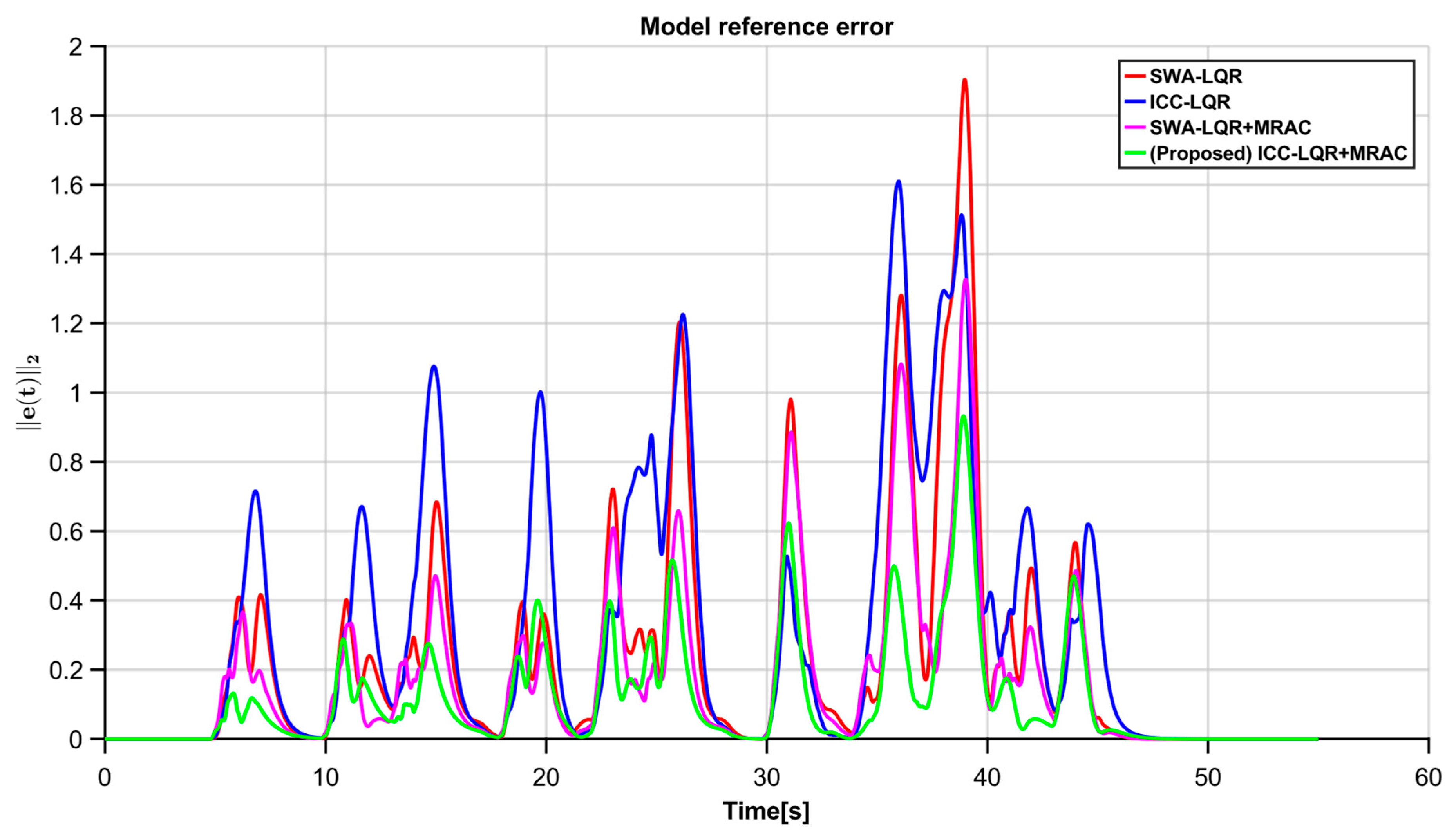
Finally, as shown in Figure 14, the L 2 norm of the reference model tracking error shows the role of adaptation in the proposed scheme. By designing the regressor ( ϕ ( t ) ) discussed in Section 4.1, which projects the reference-model error onto the system controllable input subspace, the proposed controller partially mitigates the mismatched component of crosswind/low-friction disturbances. Consequently, the tracking error to the reference model remains small for most of the maneuver, which translates into rapid convergence to the ideal LQR closed-loop state trajectory. When the crosswind intensifies in the 30–40 s window and the mismatched component grows, the proposed controller also exhibits a modest rise in ( e t 2 ); however, the σ -modification in the adaptive law permits a small residual error to prevent parameter drift, thereby maintaining closed-loop stability, after which the error quickly decays.
Quantitative evaluation was performed using the following three metrics:
R o o t   m e a n   s q u a r e   e r r o r ( R M S E ) = 1 N k = 1 N e k 2 , P e a k   e r r o r P E = max k   e k , I n t e g r a l   o f   a b s o l u t e   e r r o r I A E = k = 1 N e k T s .
RMSE is the square root of the mean of the squared path-tracking errors and indicates the average error magnitude throughout the drive. PE corresponds to the maximum instantaneous lateral deviation observed during the drive, representing the greatest departure from the intended path. IAE is the integral of the absolute error over a driving interval and quantifies the total accumulated deviation. Table 4 summarizes the measured RMSE, PE, and IAE values for each controller across the four scenarios.
Notably, the proposed controller exhibited superior performance across all scenarios. In Scenario 1, all four controllers produced small errors in response to internal parameter variations; among them, the proposed controller, ICC-LQR+MRAC, achieved the lowest RMSE and IAE values. As the disturbance conditions intensified (Scenarios 2–4), the performance gap between the controllers widened, with the largest disparities observed in Scenario 4 featuring combined disturbances. The SWA-LQR controller exhibited the largest errors, with RMSE = 0.65285 m, PE = 2.66333 m, and IAE = 21.0876 m·s. In contrast, the proposed controller achieved RMSE = 0.48856 m, PE = 1.77022 m, and IAE = 13.7968 m·s, representing improvements of 25.2%, 33.5%, and 34.6%, respectively, relative to the SWA-LQR case. The SWA-LQR+MRAC and ICC-LQR controllers, incorporating adaptive and integrated control, respectively, outperformed the SWA-LQR controller but continued to exhibit larger errors than the proposed controller. This trend persisted across all scenarios, with the relative advantage of the ICC-LQR+MRAC controller becoming especially evident under more severe driving conditions.
Quantitative evaluation using the RMSE, PE, and IAE metrics confirmed that ICC-LQR+MRAC considerably reduced path-tracking errors and enhanced vehicle stability relative to both steering-only and non-adaptive integrated control approaches. This improvement stems from the MRAC-based adaptive controller, which compensates for vehicle model uncertainties and external disturbances in real time and enhances trajectory maintenance and stability by integrating steering and torque vectoring. Taken together, these results confirm that the proposed ICC-LQR+MRAC achieved the highest path-tracking accuracy and stability, thereby demonstrating the effectiveness of the integrated chassis control strategy.
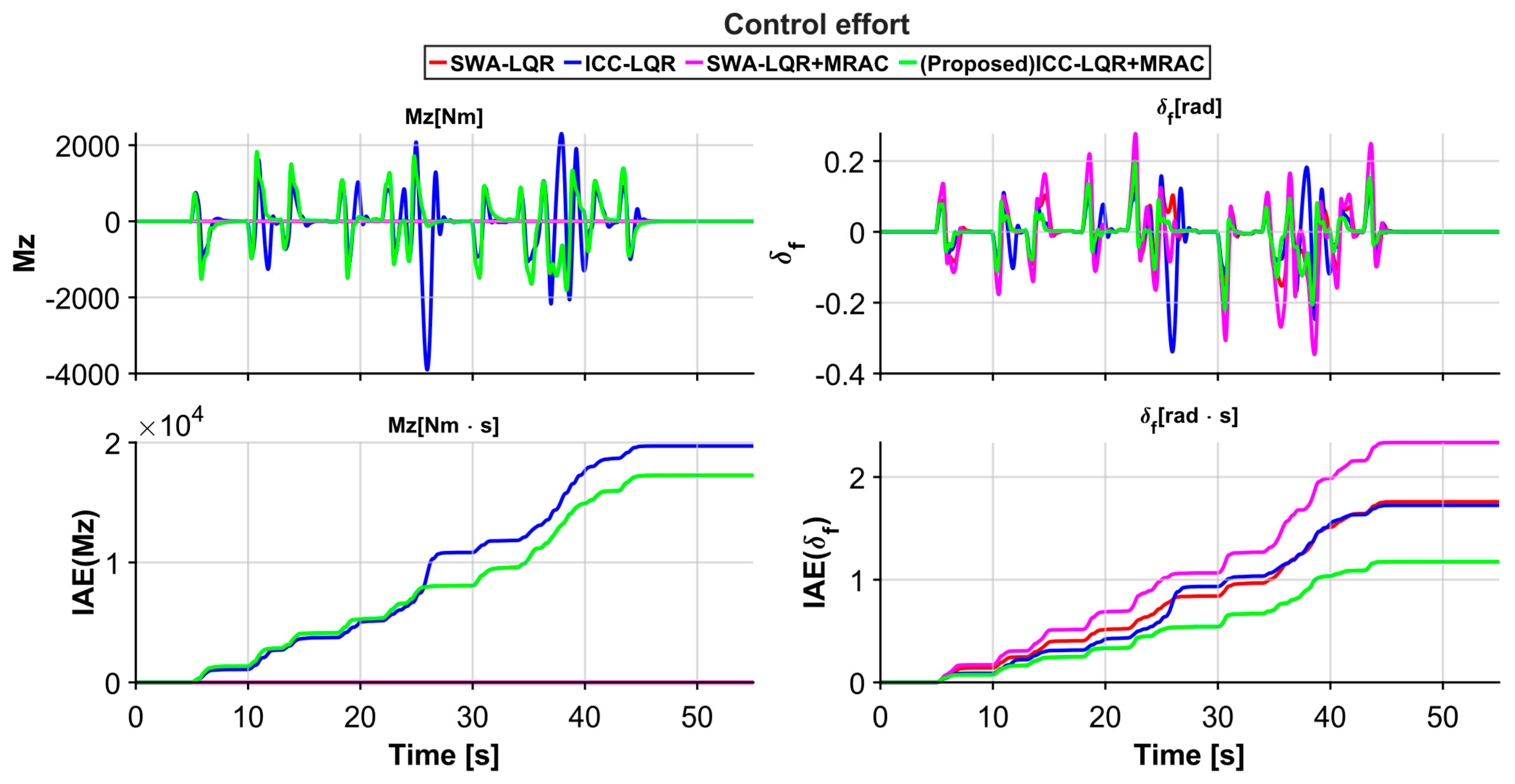
Beyond path-tracking accuracy and stability, a practically feasible chassis controller must achieve these objectives with minimal actuator usage. In over-actuated electric vehicles equipped with in-wheel motors, the way control effort is distributed between the steering system and the direct yaw-moment (DYC) channel has a direct impact on actuator saturation margins. To elucidate this performance–effort trade-off under the most demanding conditions, we therefore examine the control effort in Scenario 4 by comparing the time histories and the integral of absolute error (IAE) of the desired yaw moment and the front steering angle; Figure 15 presents the corresponding control input profiles and accumulated IAE for each control configuration.
The steering-only architecture, the MRAC augmentation must generate all additional control input through the front steering angle to reject crosswinds, split- µ friction changes, and model mismatch; this yields improved path tracking but also produces larger steering peaks and increased IAE, effectively driving the steering actuator closer to its limits and reducing stability margins compared with the nominal LQR. Concretely, SWA-LQR+MRAC exhibits the largest steering demand, with δ f m a x 0.345   rad and IAE( δ f ) 2.35   rad·s, whereas SWA-LQR requires smaller excursions ( δ f m a x 0.223 rad, IAE( δ f ) 1.76 rad·s) but still relies on relatively aggressive steering to maintain tracking. When DYC is available, the non-adaptive integrated chassis controller (ICC-LQR) expands the controllable input space, yet its fixed gains cannot actively compensate for uncertainties; as a result, even moderate errors in β and γ are mapped into relatively large yaw-moment commands, with M z , d e s m a x 4.11 × 10 3 Nm and IAE( M z , d e s ) 1.99 × 10 4 Nm·s, indicating inefficient use of the yaw channel under the combined disturbances of Scenario 4. In contrast, the proposed ICC-LQR+MRAC distributes the adaptive control input between steering and yaw-moment channels so that both IAE( δ f ) and IAE( M z , d e s ) are reduced while maintaining the smallest path-tracking errors, with IAE( δ f )   1.18 rad·s and IAE( M z , d e s ) 1.73 × 10 4 Nm·s. This behavior is consistent with the regressor design in Equations (31) and (32), where ϕ ( t ) projects the reference-model error onto the controllable input subspace so that the adaptive term allocates compensation efficiently across the steering and DYC channels, achieving an optimal balance between robustness and control effort.

6. Conclusions

This paper presents an adaptive integrated chassis control architecture that integrates a nominal LQR path-following controller, an MRAC compensator, and a constrained weighted least-squares torque allocator designed for four in-wheel motors. The upper layer generates steering and direct yaw-moment commands using the LQR. The MRAC, configured with a reference model that replicates the LQR closed-loop dynamics, performs online compensation for parametric mismatches and external disturbances. A σ-modification term is included to mitigate parameter drift and high-frequency control chatter, thereby ensuring uniform ultimate boundedness of the closed-loop signals. The lower layer translates the desired yaw moment, and longitudinal force demands into wheel torque commands while respecting static and rate constraints, enabling coordinated use of steering and torque vectoring.
The proposed fixed-gain state-feedback controller requires access to the full vehicle state, including the sideslip angle, which is difficult to measure in practice, and was validated through high-fidelity simulations assuming ideal state feedback without considering sensor noise effects. This study focused on feasibility assessment of the proposed adaptive integrated chassis control strategy to evaluate its control performance.
Future research should address robust state estimation under sensor noise, statistical validation through stochastic simulations, and comparative benchmarking against advanced robust control methods. Furthermore, to overcome the limitations of fixed gains, it is necessary to advance toward adaptive control methodologies capable of active disturbance rejection against time-varying disturbances. In particular, the extension to AI-based frameworks for dynamic adaptability is anticipated.

Author Contributions

Conceptualization, S.P. and T.O.; methodology, S.P.; software, S.P.; validation, S.P., T.O. and J.K.; investigation, S.P.; data curation, S.P. and T.O.; writing—original draft preparation, S.P.; writing—review and editing, J.Y.; visualization, S.P.; supervision, J.Y. All authors have read and agreed to the published version of the manuscript.

Funding

This work was supported by the National Research Foundation of Korea (NRF) grant funded by the Korea government (MSIT) (No. NRF-RS-2021-NR060086).

Institutional Review Board Statement

Not applicable.

Informed Consent Statement

Not applicable.

Data Availability Statement

The data presented in this study are available on request from the corresponding author. The data is not publicly available due to privacy restrictions.

Conflicts of Interest

The authors declare no conflicts of interest.

References

  1. Stano, P.; Montanaro, U.; Tavernini, D.; Tufo, M.; Fiengo, G.; Novella, L.; Sorniotti, A. Model predictive path tracking control for automated road vehicles: A review. Annu. Rev. Control 2023, 55, 194–236. [Google Scholar] [CrossRef]
  2. Olofsson, B.; Nielsen, L. Using crash databases to predict effectiveness of new autonomous vehicle maneuvers for lane-departure injury reduction. IEEE Trans. Intell. Transp. Syst. 2021, 22, 3479–3490. [Google Scholar] [CrossRef]
  3. Chen, M.; Ren, Y.; Ou, M. Adaptive robust path tracking control for autonomous vehicles considering multi-dimensional system uncertainty. World Electr. Veh. J. 2023, 14, 11. [Google Scholar] [CrossRef]
  4. Jeong, Y.; Yim, S. Integrated path tracking and lateral stability control with four-wheel independent steering for autonomous electric vehicles on low friction roads. Machines 2022, 10, 650. [Google Scholar] [CrossRef]
  5. Liu, H.; Liu, C.; Hao, L.; Zhang, D. Stability analysis of lane-keeping assistance system for trucks under crosswind conditions. Appl. Sci. 2023, 13, 9891. [Google Scholar] [CrossRef]
  6. Singh, A.S.P.; Nishihara, O. Trajectory tracking and integrated chassis control for obstacle avoidance with minimum jerk. IEEE Trans. Intell. Transp. Syst. 2022, 23, 4625–4641. [Google Scholar] [CrossRef]
  7. Liu, S.; Zhang, L.; Wang, J.; Ren, C. Cooperative control of path tracking and driving stability for intelligent vehicles on potholed road. IEEE Trans. Intell. Veh. 2023, 9, 2499–2508. [Google Scholar] [CrossRef]
  8. Cheng, S.; Li, L.; Liu, C.-Z.; Wu, X.; Fang, S.-N.; Yong, J.-W. Robust LMI-based H ∞ controller integrating AFS and DYC of autonomous vehicles with parametric uncertainties. IEEE Trans. Syst. Man. Cybern. Syst. 2021, 51, 6901–6910. [Google Scholar] [CrossRef]
  9. Dai, Y.; Wang, D. A tube model predictive control method for autonomous lateral vehicle control based on sliding mode control. Sensors 2023, 23, 3844. [Google Scholar] [CrossRef]
  10. Yang, S.; Xu, J.; Qian, Y.; Chen, L.; Yin, G. Adaptive MPC-based lateral path-tracking control for automatic vehicles. World Electr. Veh. J. 2024, 15, 95. [Google Scholar] [CrossRef]
  11. Skrickij, V.; Kojis, P.; Šabanovič, E.; Shyrokau, B.; Ivanov, V. Review of integrated chassis control techniques for automated ground vehicles. Sensors 2024, 24, 600. [Google Scholar] [CrossRef]
  12. Potluri, R.; Singh, A.K. Path-tracking control of an autonomous 4WS4WD electric vehicle using its natural feedback loops. IEEE Trans. Control Syst. Technol. 2015, 23, 2053–2062. [Google Scholar] [CrossRef]
  13. Hang, P.; Chen, X.; Luo, F. LPV/H∞ controller design for path tracking of autonomous ground vehicles through four-wheel steering and direct yaw-moment control. Int. J. Automot. Technol. 2019, 20, 679–691. [Google Scholar] [CrossRef]
  14. Sun, P.; Stensson Trigell, A.; Drugge, L.; Jerrelind, J. Energy-efficient direct yaw moment control for in-wheel motor electric vehicles utilising motor efficiency maps. Energies 2020, 13, 593. [Google Scholar] [CrossRef]
  15. Jeong, Y.; Yim, S. Path tracking control with four-wheel independent steering, driving and braking systems for autonomous electric vehicles. IEEE Access 2022, 10, 74733–74746. [Google Scholar] [CrossRef]
  16. Ren, Y.; Zheng, L.; Khajepour, A. Integrated model predictive and torque vectoring control for path tracking of 4-wheel-driven autonomous vehicles. IET Intell. Transp. Syst. 2019, 13, 98–107. [Google Scholar] [CrossRef]
  17. Tan, Q.; Dai, P.; Zhang, Z.; Katupitiya, J. MPC and PSO based control methodology for path tracking of 4WS4WD vehicles. Appl. Sci. 2018, 8, 1000. [Google Scholar] [CrossRef]
  18. Zhang, Z.; Zheng, L.; Li, Y.; Li, S.; Liang, Y. Cooperative strategy of trajectory tracking and stability control for 4WID autonomous vehicles under extreme conditions. IEEE Trans. Veh. Technol. 2023, 72, 3105–3118. [Google Scholar] [CrossRef]
  19. Na, J.; Yang, J.; Gao, G. Reinforcing transient response of adaptive control systems using modified command and reference model. IEEE Trans. Aerosp. Electron. Syst. 2020, 56, 2071–2084. [Google Scholar] [CrossRef]
  20. Liang, Y.; Li, Y.; Khajepour, A.; Zheng, L. Holistic Adaptive Multi-Model Predictive Control for the Path Following of 4WID Autonomous Vehicles. IEEE Trans. Veh. Technol. 2021, 70, 69–81. [Google Scholar] [CrossRef]
  21. Zhou, Z.; Zhang, J.; Yin, X. Adaptive sliding mode control for yaw stability of four-wheel independent-drive EV based on the phase plane. World Electr. Veh. J. 2023, 14, 116. [Google Scholar] [CrossRef]
  22. Lee, J.E.; Kim, B.W. A novel adaptive non-singular fast terminal sliding mode control for direct yaw moment control in 4WID electric vehicles. Sensors 2025, 25, 941. [Google Scholar] [CrossRef]
  23. Meléndez-Useros, M.; Viadero-Monasterio, F.; Jiménez-Salas, M.; López-Boada, M.J. Static Output-Feedback Path-Tracking Controller Tolerant to Steering Actuator Faults for Distributed Driven Electric Vehicles. World Electr. Veh. J. 2025, 16, 40. [Google Scholar] [CrossRef]
  24. Tan, X.; Liu, D.; Xiong, H. Optimal control method of path tracking for four-wheel steering vehicles. Actuators 2022, 11, 61. [Google Scholar] [CrossRef]
  25. Hu, J.; Zhang, K.; Zhang, P.; Yan, F. Direct yaw moment control for distributed drive electric vehicles based on hierarchical optimization control framework. Math 2024, 12, 1715. [Google Scholar] [CrossRef]
  26. Nguyen, K.-D. A Predictor-Based Model Reference Adaptive Controller for Time-Delay Systems. IEEE Trans. Autom. Control 2018, 63, 4375–4382. [Google Scholar] [CrossRef]
  27. Narendra, K.S.; Annaswamy, A.M. Stable Adaptive Systems; Prentice Hall: Englewood Cliffs, NJ, USA, 1989; ISBN 978-0138399948. [Google Scholar]
  28. Ioannou, P.A.; Kokotović, P.V. Instability analysis and improvement of robustness of adaptive control. Automatica 1984, 20, 583–594. [Google Scholar] [CrossRef]
  29. Lavretsky, E.; Wise, K.A. Robust and Adaptive Control: With Aerospace Applications; Springer: London, UK, 2013; ISBN 978-1-4471-4395-6. [Google Scholar]
  30. Lavretsky, E.; Gadient, R.; Gregory, I.M. Predictor-based model reference adaptive control. J. Guid. Control Dyn. 2010, 33, 1195–1200. [Google Scholar] [CrossRef]
  31. Byrne, R.H.; Abdallah, C.T. Design of a model reference adaptive controller for vehicle road following. Math. Comput. Model. 1995, 22, 343–354. [Google Scholar] [CrossRef]
  32. Zhou, X.; Wang, Z.; Shen, H.; Wang, J. Yaw-rate-tracking-based automated vehicle path following: An MRAC methodology with a closed-loop reference model. ASME Lett. Dyn. Syst. Control 2021, 2, 021010. [Google Scholar] [CrossRef]
  33. Lee, D.; Jang, K.; Lee, S.; Kim, L.; Bang, H. Closed-Loop MRAC Augmented LQR with Integral Action for Quadrotor UAV under the Uncertainties. In Advances in Aerospace Guidance, Navigation and Control: Proceedings of the 2022 CEAS EuroGNC Conference; Springer: Cham, Switzerland, 2022; pp. 30–45. [Google Scholar]
  34. Yang, G.; Yao, J. Multilayer neurocontrol of high-order uncertain nonlinear systems with active disturbance rejection. Int. J. Robust Nonlinear Control 2024, 34, 2972–2987. [Google Scholar] [CrossRef]
  35. Dixit, S.; Montanaro, U.; Dianati, M.; Oxtoby, D.; Mizutani, T.; Mouzakitis, A.; Fallah, S. Integral MRAC with bounded switching gain for vehicle lateral tracking. IEEE Trans. Control Syst. Technol. 2021, 29, 1711–1722. [Google Scholar] [CrossRef]
  36. Montanaro, U.; Chen, C.; Rizzo, A.; Sorniotti, A. Output-Based Enhanced Closed-Loop Model Reference Adaptive Control and Its Application to Direct Yaw Moment Control. Int. J. Robust Nonlinear Control 2024, 34, 9471–9500. [Google Scholar] [CrossRef]
  37. Park, M.; Yim, S. Design of static output feedback integrated path tracking controller for autonomous vehicles. Processes 2025, 13, 1335. [Google Scholar] [CrossRef]
  38. Yin, D.; Wang, J.; Du, J.; Chen, G.; Hu, J.-S. A new torque distribution control for four-wheel independent-drive electric vehicles. Actuators 2021, 10, 122. [Google Scholar] [CrossRef]
  39. Rajamani, R. Vehicle Dynamics and Control, 3rd ed.; Springer: New York, NY, USA, 2012. [Google Scholar]
  40. Wang, W.; Ma, T.; Yang, C.; Zhang, Y.; Li, Y.; Qie, T. A path-following lateral control scheme for four-wheel independent drive autonomous vehicle using sliding mode prediction control. IEEE Trans. Transp. Electrific. 2022, 8, 3192–3207. [Google Scholar] [CrossRef]
  41. Khalil, H.K. Nonlinear Systems, 3rd ed.; Prentice Hall: Upper Saddle River, NJ, USA, 2002; ISBN 978-0-13-067389-3. [Google Scholar]
  42. Ioannou, P.A.; Sun, J. Robust Adaptive Control; Prentice Hall: Upper Saddle River, NJ, USA, 1996; ISBN 978-0-13-439100-7. [Google Scholar]
  43. Naqvi, S.S.A.; Jamil, H.; Iqbal, N.; Khan, S.; Khan, M.; Qayyum, F.; Kim, D.-H. Evolving electric mobility: In-depth analysis of integrated electronic control unit development in electric vehicles. IEEE Access 2024, 12, 15957–15983. [Google Scholar] [CrossRef]
  44. Li, B.; Ahmadi, J.; Lin, C.; Siampis, E.; Longo, S.; Velenis, E. Integrated path-tracking and control allocation controller for autonomous electric vehicle under limit handling condition. In Proceedings of the 2020 IEEE Intelligent Vehicles Symposium (IV), Las Vegas, NV, USA, 19 October–13 November 2020; IEEE: Las Vegas, NV, USA, 2020; pp. 1–8. [Google Scholar] [CrossRef]
  45. Johansen, T.A.; Fossen, T.I. Control allocation—A survey. Automatica 2013, 49, 1087–1103. [Google Scholar] [CrossRef]
  46. Yong, J.; Gao, F.; Ding, N.; He, Y. An integrated algorithm for vehicle stability improvement with the coordination of direct yaw moment and four-wheel steering control. Int. J. Veh. Des. 2017, 74, 231–256. [Google Scholar] [CrossRef]
  47. Anderson, B.D.O.; Moore, J.B. Optimal Control: Linear Quadratic Methods; Prentice-Hall: Englewood Cliffs, NJ, USA, 1989; ISBN 978-0-13-638560-8. [Google Scholar]
  48. Kang, J.; Yi, K.; Heo, H. Control allocation–based optimal torque vectoring for 4WD electric vehicle. In Proceedings of the 2012 SAE World Congress & Exhibit; SAE Technical Paper 2012-01-0246; Springer: Berlin/Heidelberg, Germany, 2012. [Google Scholar] [CrossRef]
  49. Lee, S.; Kim, K.; Moon, S.; Kim, B.; Ahn, J.; Hwang, J.; Kim, D.; Woo, S.; Yoo, J. A novel lateral dynamics control strategy of in-wheel motor vehicle to improve agility and straight-line driving stability. IEEE Trans. Veh. Technol. 2024, 73, 9849–9864. [Google Scholar] [CrossRef]
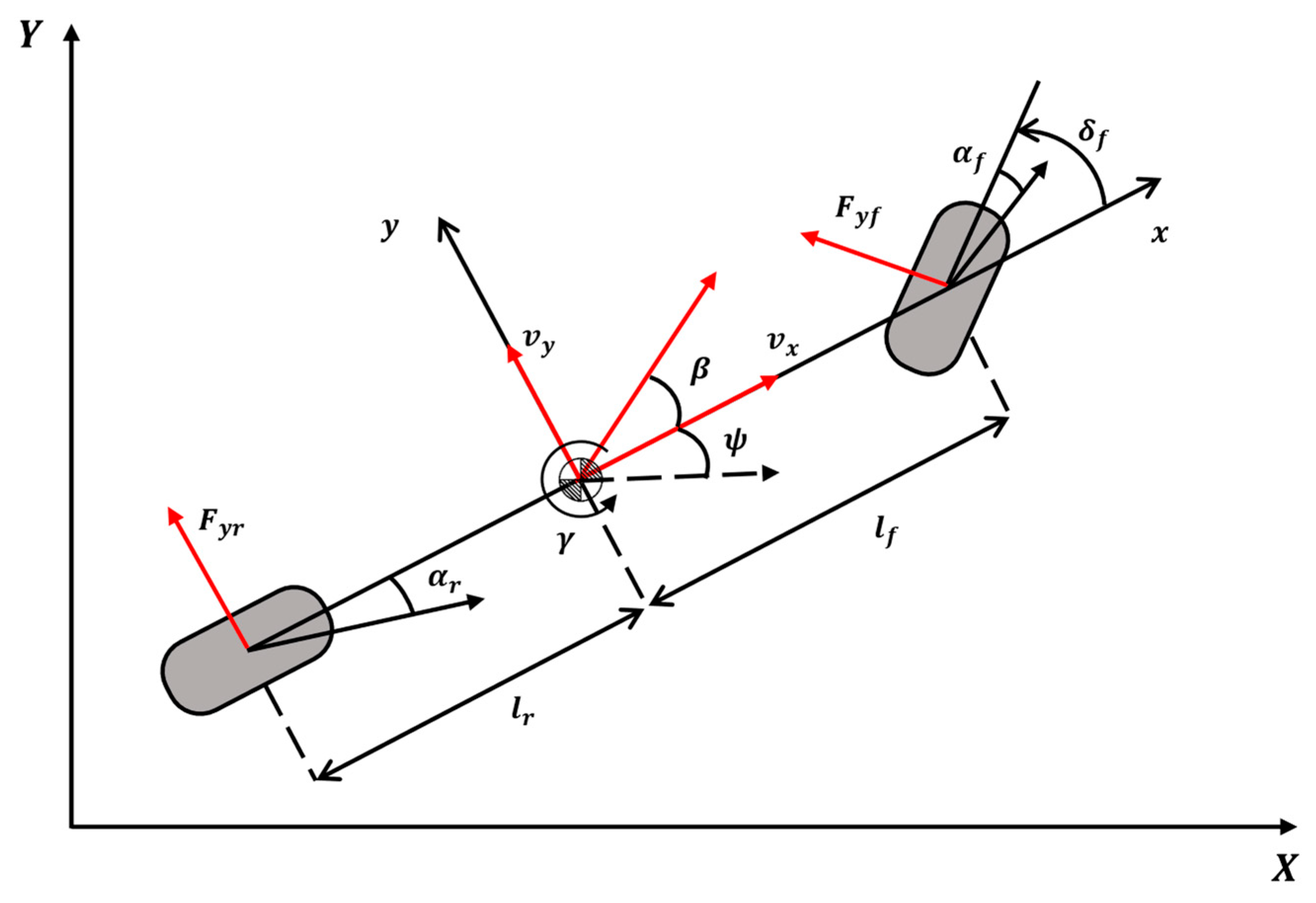
Figure 1. Two-degree-of-freedom (2-DOF) vehicle dynamics model.
Applsci 15 12387 g001
Figure 2. Schematic of the 7-DOF vehicle dynamics model.
Applsci 15 12387 g002
Figure 3. Standard model reference adaptive control (MRAC) architecture.
Applsci 15 12387 g003
Figure 4. Overall architecture of the proposed adaptive integrated chassis controller.
Applsci 15 12387 g004
Figure 5. Simulation environment of the proposed controller.
Applsci 15 12387 g005
Figure 6. Reference signal used for the path-tracking controller.
Applsci 15 12387 g006
Figure 7. Vehicle velocity profile for the longitudinal controller.
Applsci 15 12387 g007
Figure 8. Disturbance factors influencing the driving environment: (a) crosswind speed profile; (b) split-μ road friction distribution.
Applsci 15 12387 g008
Figure 9. Simulation result of scenario 1.
Applsci 15 12387 g009
Figure 10. Simulation result of scenario 2.
Applsci 15 12387 g010
Figure 11. Simulation result of scenario 3.
Applsci 15 12387 g011
Figure 12. Simulation result of scenario 4.
Applsci 15 12387 g012
Figure 13. Stability result of scenario 4.
Applsci 15 12387 g013
Figure 14. Reference model error norm.
Applsci 15 12387 g014
Figure 15. Control effort results.
Applsci 15 12387 g015
Table 1. Parameters of the nominal vehicle model.
SymbolValueUnit
v x , i n i t 25 m / s
m 2065.03 k g
I z z 3637.526 k g · m 2
l f 1.801 m
l r 1.169 m
l w 1.638 m
C f 149,744 N / r a d
C r 93,678 N / r a d
Table 2. Scenario conditions.
No.Mass Increase
[+180 kg]
Road Friction
μ   = [0.4, 0.8]
Cross Winds
[15, 30 m/s]
SCENARIO 1OXX
SCENARIO 2OXO
SCENARIO 3OOX
SCENARIO 4OOO
Table 3. Parameters of the controller.
SymbolValue
K x ,   K ^ x T ( 0 ) 2.24 1.76 348.31 22.80 0.09 0.21 1.68 0.08
K r , K ^ r T ( 0 ) 2.24 348.31 0.09 1.68
Γ x ,   Γ θ 100 100 100 100 0.01 0.01 0.01 0.01 T
Γ r 100 100 0.01 0.05 T
σ x ,   σ r ,   σ θ 0.01
Table 4. Quantitative results across all scenarios.
Scenario 1Lateral Deviation [ e y ]Heading Error [ e ψ ]
RMSE [m]PE [m]IAE [ms]RMSE [rad]PE [rad]IAE [rad·s]
SWA-LQR0.540371.7417716.21690.04142050.1313081.29172
SWA-LQR+MRAC0.4088071.3695211.66880.03496660.1283380.997914
ICC-LQR0.4543191.5219512.68610.03278330.1122210.952673
Proposed0.4025581.3411211.57770.02468660.07914890.740466
Scenario 2Lateral Deviation [ e y ]Heading Error [ e ψ ]
RMSE [ m ]PE [ m ]IAE [ m · s ]RMSE [ r a d ]PE [ r a d ]IAE [ r a d · s ]
SWA-LQR0.5670651.9501818.33110.04161510.1306011.34098
SWA-LQR+MRAC0.4426671.7232912.58130.03430420.122571.02393
ICC-LQR0.4670751.787113.94670.03274860.1070250.995802
Proposed0.4396881.6854812.09130.02441420.08934030.735768
Scenario 3Lateral Deviation [ e y ]Heading Error [ e ψ ]
RMSE [ m ]PE [ m ]IAE [ m · s ]RMSE [ r a d ]PE [ r a d ]IAE [ r a d · s ]
SWA-LQR0.5823721.815217.510.04258160.1331441.34851
SWA-LQR+MRAC0.4990451.6123815.47940.03987130.1333741.24944
ICC-LQR0.5053081.6463414.20310.03362650.1145540.994984
Proposed0.4770971.5964813.14110.02621970.08775090.781502
Scenario 4Lateral Deviation [ e y ]Heading Error [ e ψ ]
RMSE [ m ]PE [ m ]IAE [ m · s ]RMSE [ r a d ]PE [ r a d ]IAE [ r a d · s ]
SWA-LQR0.652852.6633321.08760.04385570.1532381.4379
SWA-LQR+MRAC0.5692212.2680918.37780.04235060.159921.3676
ICC-LQR0.5812712.7002117.50420.03593110.1417371.13054
Proposed0.488561.7702213.79680.02704360.09491640.834595
Disclaimer/Publisher’s Note: The statements, opinions and data contained in all publications are solely those of the individual author(s) and contributor(s) and not of MDPI and/or the editor(s). MDPI and/or the editor(s) disclaim responsibility for any injury to people or property resulting from any ideas, methods, instructions or products referred to in the content.