Article

One More Thing on the Subject: Prediction of Chaos in a Josephson Junction with Quadratic Damping by the Melnikov Technique, Possible Probabilistic Control over Oscillations

1
Faculty of Mathematics and Informatics, University of Plovdiv Paisii Hilendarski, 24, Tzar Asen Str., 4000 Plovdiv, Bulgaria
2
Institute of Mathematics and Informatics, Bulgarian Academy of Sciences, Acad. G. Bonchev Str., Bl. 8, 1113 Sofia, Bulgaria
3
Centre of Excellence in Informatics and Information and Communication Technologies, 1113 Sofia, Bulgaria
4
Faculty of Mathematics and Informatics, Sofia University “St. Kliment Ohridski”, 5, James Bourchier Blvd., 1164 Sofia, Bulgaria
*
Author to whom correspondence should be addressed.
Appl. Sci. 2025, 15(23), 12359; https://doi.org/10.3390/app152312359
Submission received: 29 August 2025 / Revised: 1 October 2025 / Accepted: 19 November 2025 / Published: 21 November 2025
(This article belongs to the Special Issue Nonlinear Dynamics in Mechanical Engineering and Thermal Engineering)

Abstract

Many authors analyze the prediction of chaos in a Josephson junction with quadratic damping by the Melnikov technique. Due to the lack of an explicit presentation of the Melnikov integral, the researchers apply numerical methods and illustrative examples to verify a good agreement between the numerical method and the analytical one. The reader has difficulty navigating and touching upon Melnikov’s elegant theory and, in particular, the formulation of the Melnikov criterion for the possible occurrence of chaos in a dynamical system, based solely on the provided illustrations of dependencies between the main parameters of the model under consideration. The statements in a number of publications devoted to this interesting topic, such as “It is easy to see that Melnikov’s integrals are finite and not zero. It is possible to see that the transverse zeros of the Melnikov function”, do not shed enough light on the origin of the “horseshoe”-type chaos. In this paper we will try to shed additional light on this important problem. A new planar system corresponding to the N-generalized Josephson junction with quadratic damping with many free parameters is considered, which may be of interest to specialists in the field of engineering sciences. Prediction of chaos in the proposed model by the Melnikov technique is closely related to the problem of approximately simultaneously finding all roots (simple or multiple) of generalized trigonometric polynomials. Several simulations are composed. We also demonstrate some specialized modules for investigating the dynamics of the model. One application about generating stochastic construction for possible control over oscillations is also discussed.

1. Introduction

Superconducting quantum interference devices, or SQUIDs, are extremely sensitive devices designed specifically for measuring extremely low magnetic fields.
Applications for these systems can be found in many real-world domains, including biology, geology, medicine, and numerous engineering specialties.
The Josephson effect and superconductors serve as the primary foundation for their characteristics. Ford Research Labs built direct current (DC) and radio frequency (RF) SQUIDs in the 1960s; we mention the original work [1] and the groundbreaking manuals [2,3].
Melnikov’s method at a saddle–node, the dynamics of the forced Josephson junction, homoclinic and heteroclinic bifurcations in rf SQUIDs, the chaotic dynamics of periodically driven rf superconducting quantum interference devices, and the odd and even subharmonics and chaos in rf SQUIDs are all covered in detail in the outstanding studies [4,5,6,7,8,9,10,11,12].
Investigations on the dynamics of a modified rf-SQUIDs model: simulations and possible control over oscillations fan be found in [13].
Engineering-oriented considerations can be found in [14,15,16]. Interesting reviews on the topics: inductive reply of high-Tc rf SQUID in the presence of large thermal fluctuations; theoretical study of an rf-SQUID operation taking into account the noise influence and signal characteristics for high-Tc rf SQUID from its small signal voltage-frequency characteristics the reader can find in [17,18,19].
Josephson junctions are of interest for applications such as voltage standards [20], SQUID magnetometers [21], particle detectors [22], and energy-efficient superconductor logic and memory circuits [23,24].
Many authors have worked on the topic of solitary waves in the sine-Gordon model of the two-dimensional Josephson junction (see, for example, ref. [25]).
The Josephson junction with linear or quadratic damping is the subject of research by many researchers (see, for example, some basic publications [26,27,28,29,30,31]).
Some non-standard research on quadratic damped and forced nonlinear oscillators in general can be found in [32].
The authors of [33] extend Melnikov’s [34] approach to predict chaos in a Josephson junction with quadratic damping and examine the findings of Salam and Sastry [31] from the perspective of Josephson-junction applications.
More precisely, Bartuccelli et al. [33] devote their research to the following planar system:
d x d t = y d y d t = sin x k y 2 + ρ 0 + ϵ ρ ρ 0 + ρ 1 sin ( ω t ) .
After formulation of the Melnikov criterion for the possible occurrence of chaos in a dynamical system, based solely on the provided illustrations of dependencies between the main parameters of the model under consideration, the authors are satisfied with the statement: “It is easy to see that Melnikov’s integrals are finite and not zero. It is possible to see that there are transverse zeros of the Melnikov function” do not shed enough light on the origin of the “horseshoe”-type chaos.
It is well known that chaos arises in the differential model under consideration if M ( t 0 ) = 0 and d M ( t 0 ) d t 0 0 for some t 0 and some sets of parameters.
In this paper we will try to shed additional light on this important problem. A new planar system corresponding to the N-generalized Josephson junction with quadratic damping with many free parameters is considered in Section 2, which may be of interest to specialists in the field of engineering sciences.
Prediction of chaos in the proposed model by the Melnikov technique is closely related to the problem of approximately simultaneous finding of all roots (simple or multiple) of generalized trigonometric polynomials. A number of intriguing simulations are created.
We also show a few specific modules for examining the new model’s dynamics. Section 3 also discusses an application that generates stochastic constructions for potential oscillation control. Finally, we conclude in Section 4. Useful simulations are made.

2. A New Model— Some Simulations

We consider the following new modified model of the form:
d x d t = y d y d t = sin x k y 2 + ρ 0 + ϵ ρ ρ 0 + i = 1 N ρ i sin ( i ω t ) ,
where 0 ϵ < 1 , k > 0 , ω > 0 , ρ 0 > 0 , ρ > 0 , ρ i 0 , i = 1 , 2 , N and N is an integer.
It is known that the heteroclinic orbits are of the following form [33,35]:
x h e t ( t ) = 4 arctan ( e b t 2 ) β π y h e t ( t ) = b sech b t 2 ,
where b = 2 ρ 0 k and β = arctan ( 2 k ) .
The heteroclinic orbits for k = 0.1 ; ρ 0 = 0.396 ; b = 1.9797 ; β = 0.197396 are depicted in Figure 1.
We note that the Melnikov function [34] corresponding to model (2) is of the following form:
M ( t 0 ) = b sech b ( t t 0 ) 2 ρ ρ 0 + i = 1 N ρ i sin ( i ω t ) e 0 t t 0 2 k b sech b t 2 d t d t .
After some transformations and calculations, it is not difficult to see the following:
M ( t 0 ) = ( ρ ρ 0 ) sinh ( 2 π k ) k + b i = 1 N ρ i I i cos ( i ω t 0 ) + J i sin ( i ω t ) ,
where
I i = sech b t 2 sin ( i ω t ) e 4 k arctan sinh b t 2 d t ,
J i = sech b t 2 cos ( i ω t ) e 4 k arctan sinh b t 2 d t
for i = 1 , 2 , , N .
Remark 1.
In the particular case of N = 1 , from the representation (5) for the Melnikov criteria for the possible occurrence of chaos in the dynamical model we obtain the following:
ρ 1 > ( ρ ρ 0 ) sinh ( 2 π k ) k b I 1 2 + J 1 2 1 2 .
This result coincides with the one obtained in the article [33].
Remark 2.
For any arbitrary N, the reader can define the Melnikov criterion for the occurrence of chaos in the dynamical system under consideration. The integrals I i and J i can be calculated numerically. As a result of these calculations, M ( t 0 ) actually represents a generalized trigonometric polynomial.
The verification of the above-mentioned conditions, M ( t 0 ) = 0 and d M ( t 0 ) d t 0 0 , implies the knowledge of all zeros of the generalized trigonometric polynomial. This requires the use of specialized numerical algorithms for simultaneously finding all zeros (simple or multiple) of the polynomial in confidential intervals (see, for example, refs. [36,37,38,39]).
The planned (by us) web-based application [40] has such a specialized module implemented in the CAS Mathematica.
We will illustrate what has been said with two relevant examples.
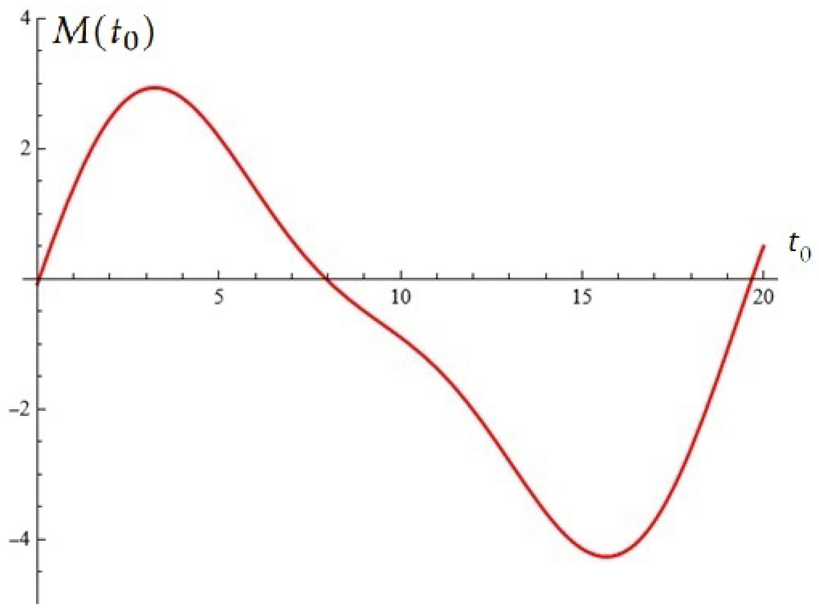
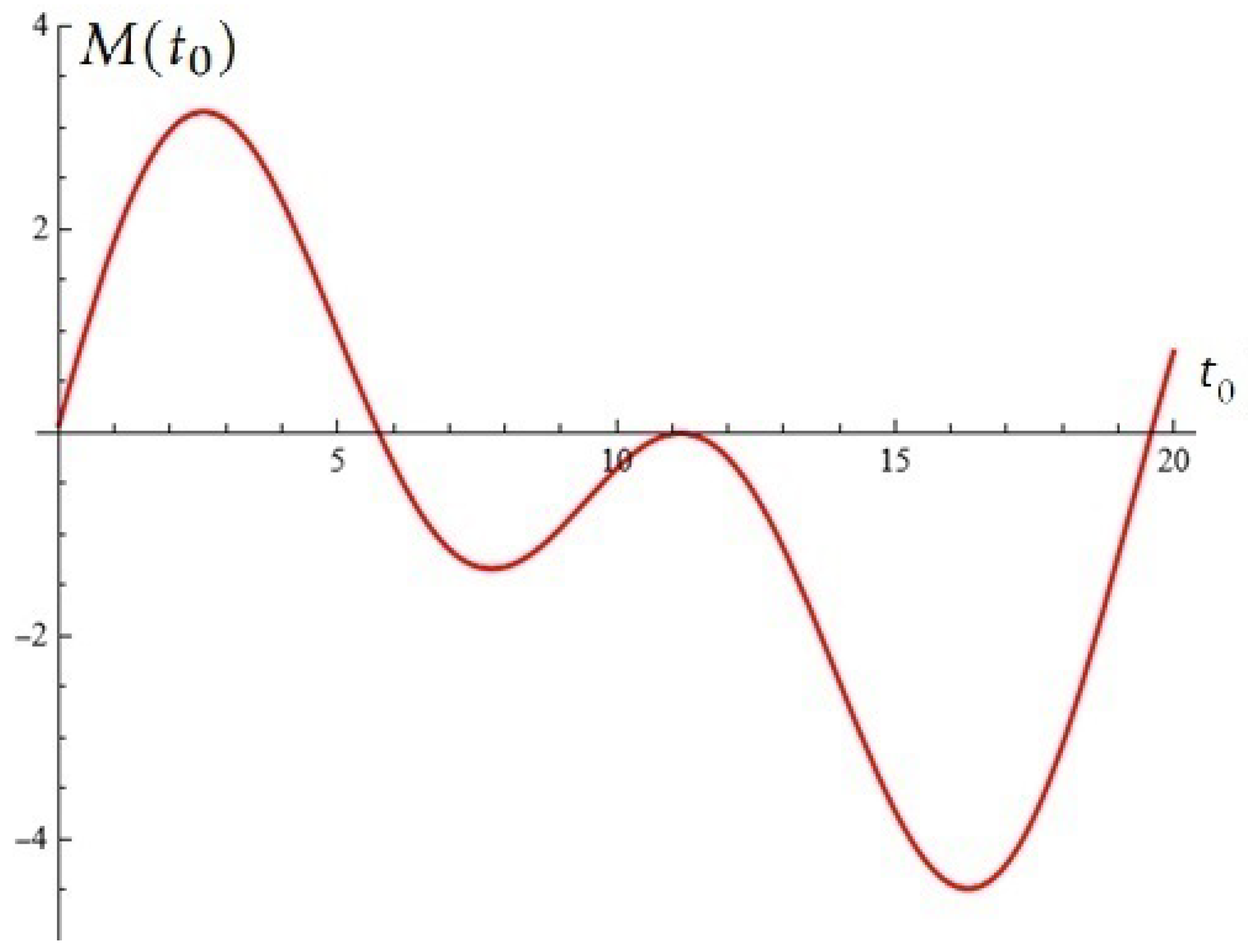
Numerical example 1. Let us fix N = 2 ; ω = 0.32 ; k = 0.1 ; ρ 0 = 0.4 ; ρ = 0.3 ; b = 2.82843 .
(a) For ρ 1 = 0.5 ; ρ 2 = 0.18 , from (5) for the Melnikov polynomial we obtain the following:
M ( t 0 ) = 0.670484 + 2.82843 0.5 ( 0.26254 cos ( 0.32 t 0 ) + 2.21692 sin ( 0.32 t 0 ) ) + 0.18 ( 0.432356 cos ( 0.64 t 0 ) + 1.83909 sin ( 0.6 t 0 ) ) .
From Figure 2 it can be seen that M ( t 0 ) has a unique root t 0 = 7.94327 in the interval ( 0 , 19 ) .
(b) For ρ 1 = 0.36 ; ρ 2 = 0.3895 , from (5) for the Melnikov polynomial we obtain the following:
M ( t 0 ) = 0.670484 + 2.82843 0.36 ( 0.26254 cos ( 0.32 t 0 ) + 2.21692 sin ( 0.32 t 0 ) ) + 0.3895 ( 0.432356 cos ( 0.64 t 0 ) + 1.83909 sin ( 0.6 t 0 ) ) .
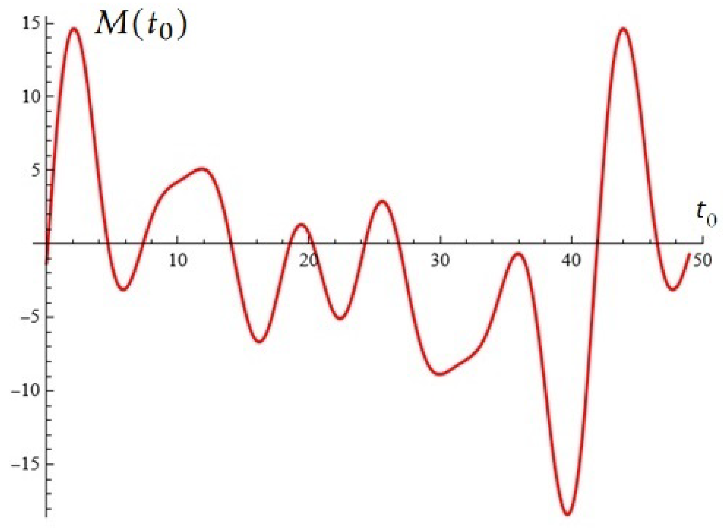
From Figure 3 it can be seen that M ( t 0 ) has simple root t 0 = 5.94 and root t 0 11.14 (with multiplicity two) in interval ( 0 , 19 ) .
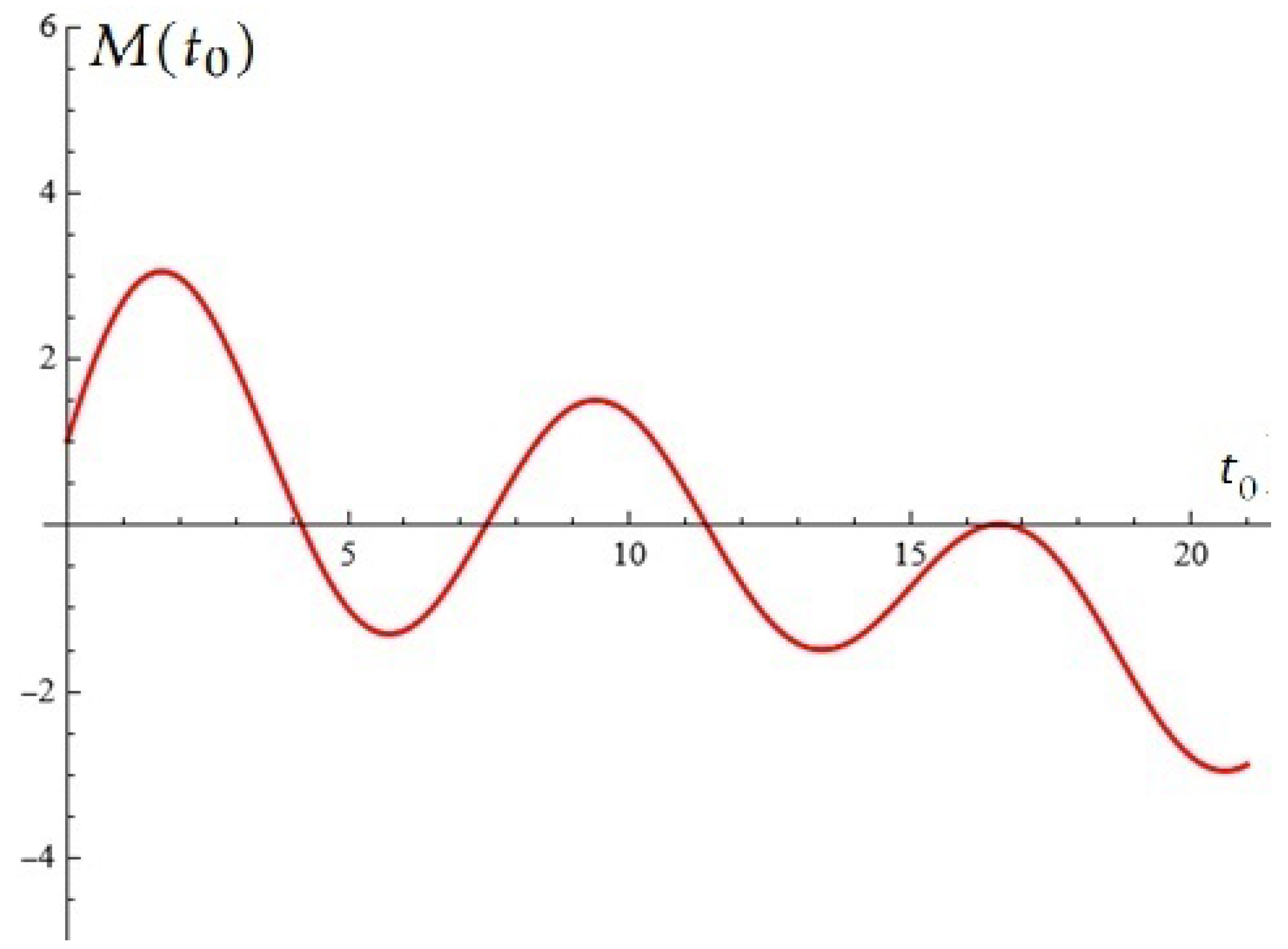
Numerical example 2. Let us fix N = 4 ; ω = 0.2 ; k = 0.15 ; ρ 0 = 0.3 ; ρ = 0.2 ; b = 2 .
For ρ 1 = 0.2 ; ρ 2 = 0.1 ; ρ 3 = 0.2 ; ρ 4 = 0.435 , from (5) for the Melnikov polynomial we obtain the following:
M ( t 0 ) = 0.725557 + 2 0.2 ( 0.7223 cos ( 0.2 t 0 ) + 3.42596 sin ( 0.2 t 0 ) ) + 0.1 ( 0.901004 cos ( 0.4 t 0 ) + 2.91146 sin ( 0.4 t 0 ) ) + 0.2 ( 1.06607 cos ( 0.6 t 0 ) + 2.27559 sin ( 0.6 t 0 ) ) + 0.435 ( 1.06849 cos ( 0.8 t 0 ) + 1.67596 sin ( 0.8 t 0 ) ) .
From Figure 4 it can be seen that M ( t 0 ) has simple roots and root t 0 16.38 (with multiplicity two) in interval ( 0 , 19 ) .
Figure 2. Melnikov function M ( t 0 ) : Numerical example 1 (a).
Applsci 15 12359 g002
Figure 3. Melnikov function M ( t 0 ) : Numerical example 1 (b).
Applsci 15 12359 g003
Figure 4. Melnikov function M ( t 0 ) : Numerical example 2.
Applsci 15 12359 g004
Some Simulations
We provide an efficient study strategy that emphasizes learning and challenges our PhD students to consider the triangle of enigmatics, creativity, and acmeology. Since mathematical modeling is based on dynamic processes, the suggested differential systems allow us to achieve the aforementioned trio. A thorough analysis of this subject can be found in the outstanding monograph [41]. We will consider some examples.
Example 1
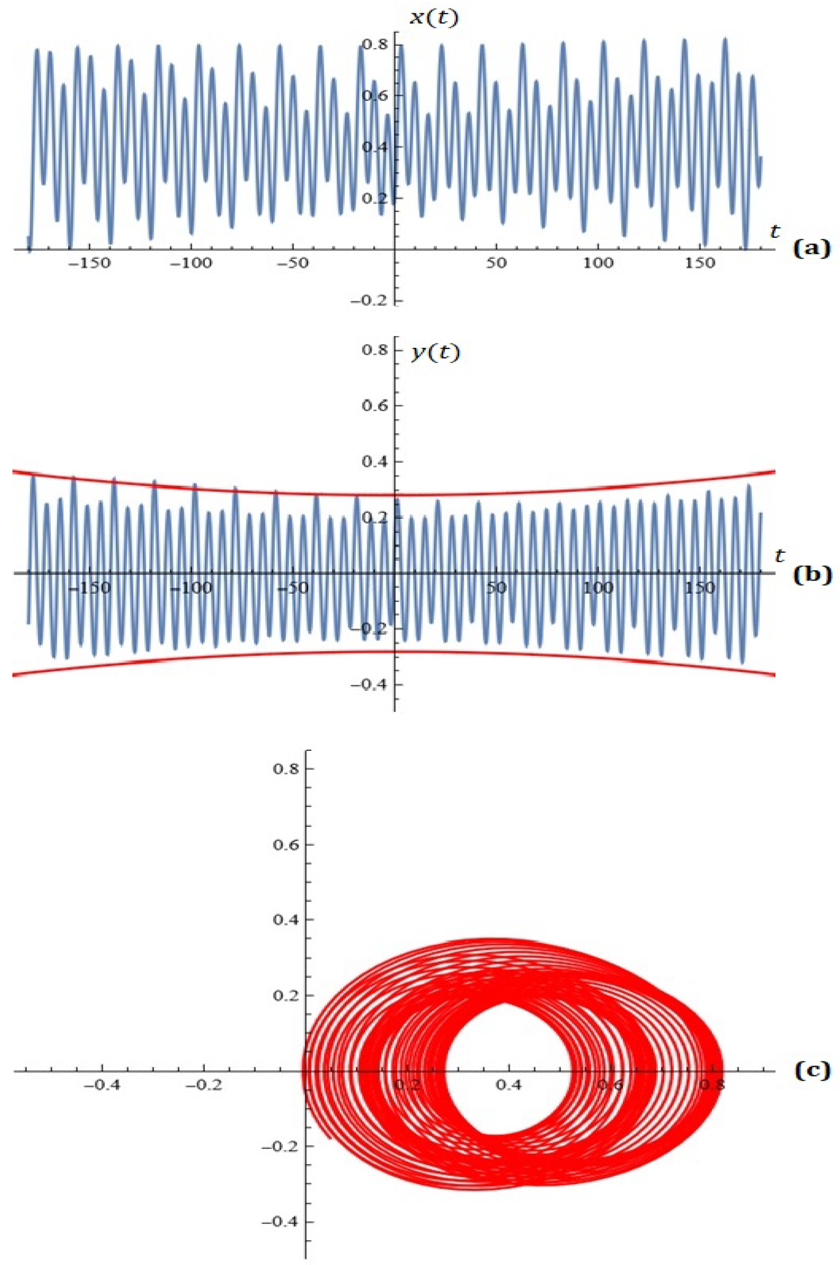
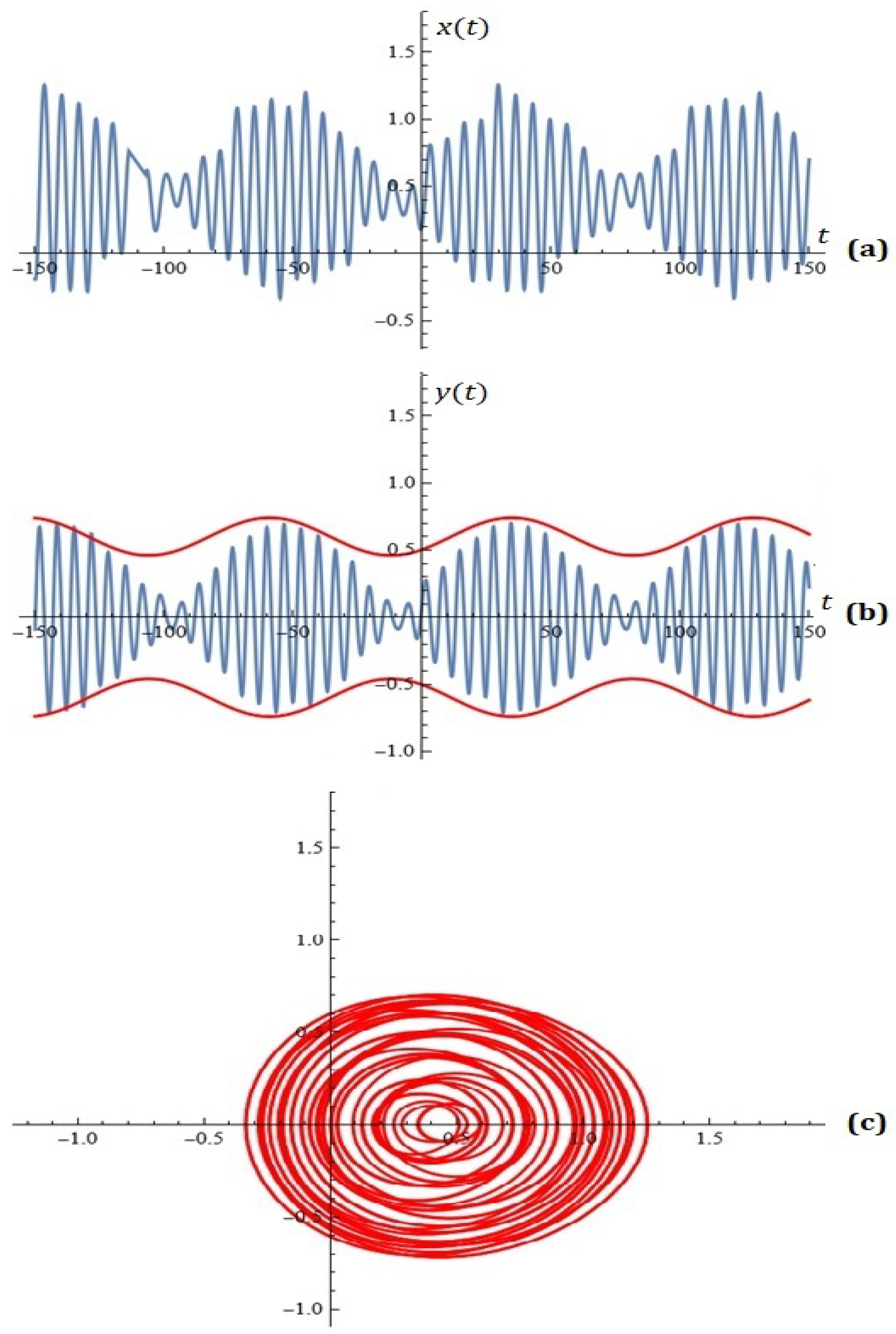
(study example). If the extra user restriction is applied, the oscillations on the y-component of the system solutions fall into the fork ( F ( t ) , F ( t ) ) , where F ( t ) = 0.28 + 8.641975 × 10 6 t 2 . For example, if N = 2 , ϵ = 0.1 , and x 0 = 0.2 are given, y 0 = 0.1 and y 0 = 0.1 generate an adequate simulation of model (2).
Following their use of the specialized module we provided (which includes additional approximation and optimization algorithms) implemented in CAS Mathematica, the students arrive at the task’s solution with relative ease: k = 0.1 , ω = 0.32 , ρ 0 = 0.4 , ρ = 0.53 , ρ 1 = 0.9 , ρ 2 = 0.2 (see Figure 5).
Example 2
(study example). For given N = 4 , ϵ = 0.055 and x 0 = 0.2 ; y 0 = 0.1 generate an appropriate simulation of model (2), if the oscillations on the y-component of the system solutions fall into the fork ( F ( t ) , F ( t ) ) , where F ( t ) = 0.6 + 0.1 sin ( 0.067 ( t + 0.49 ) ) + 0.1 cos ( 0.067 ( t + 0.49 ) ) .
After using the specialized module mentioned above, students relatively easily reach the answer to the problem: k = 0.04 , ω = 0.25 , ρ 0 = 0.4 , ρ = 0.53 , ρ 1 = 0.7 , ρ 2 = 0.5 , ρ 3 = 0.1 , ρ 4 = 0.7 (see Figure 6).
Example 3
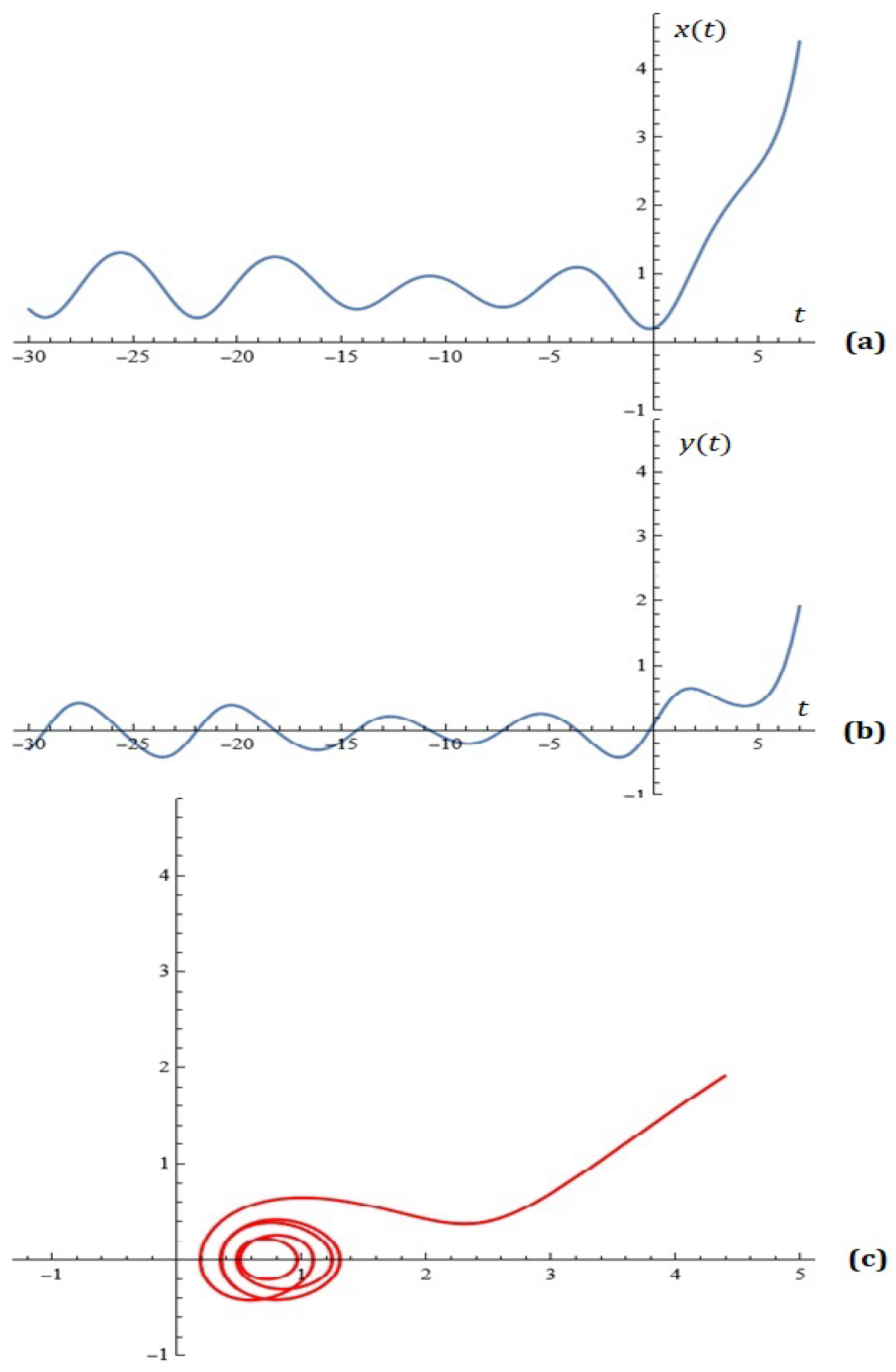
(study example). For given N = 7 , ϵ = 0.055 , k = 0.03 , ω = 0.15 , ρ 0 = 0.7 , ρ = 0.4 , ρ 1 = 0.7 , ρ 2 = 0.5 , ρ 3 = 0.1 , ρ 4 = 0.7 , ρ 5 = 0.9 , ρ 6 = 0.2 , ρ 7 = 0.5 the simulations on the system (2) for x 0 = 0.2 ; y 0 = 0.1 are depicted on Figure 7.
Challenges for Learners
Task 1. (i) Try to obtain an explicit representation of the first Melnikov function corresponding to the differential model (with the data from Example 3);
(ii) draw the appropriate conclusions;
(iii) Find all zeros of the equation M ( t 0 ) = 0 and for each root test Melnikov’s criterion.
Answer: If the problem is solved correctly, you should obtain the approximate illustration shown in Figure 8.
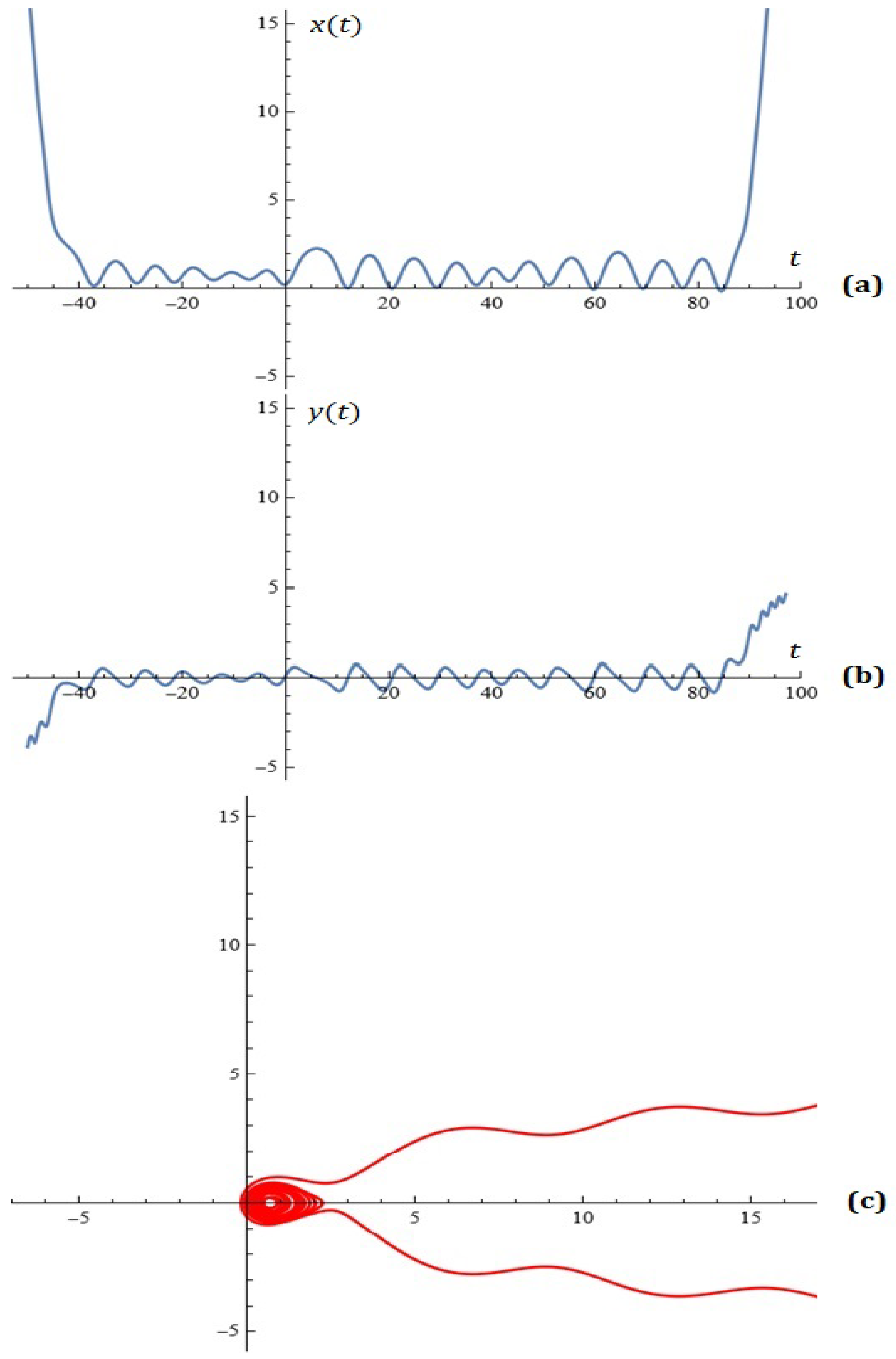
Task 2. For fixed value N = 8 using the provided program module, indicate for what values of the parameters of the studied model the approximate illustration of the phase portrait indicated in Figure 9 is obtained.
Answer: ϵ = 0.055 , k = 0.03 , ω = 0.15 , ρ 0 = 0.7 , ρ = 0.9 , ρ 1 = 0.7 , ρ 2 = 0.5 , ρ 3 = 0.1 , ρ 4 = 0.7 , ρ 5 = 0.9 , ρ 6 = 0.2 , ρ 7 = 0.5 , ρ 8 = 0.02 .
Applications
A potential use of the Melnikov functions in the modeling and synthesis of antenna schematics was covered in our earlier publications.
We define the hypothetical normalized antenna factor as follows:
M * ( θ ) = 1 D | M ( K cos θ + k 1 ) | ,
where θ is the azimuth angle; K = k d ; k = 2 π λ ; ( λ is the wave length; d is the distance between emitters; k 1 is the phase difference, and D = max M ( θ ) in considered interval). Usually d is chosen as a function of wave length, i.e., d = g ( λ ) .
The general N-element linear phased array factor used to find A k coefficients is calculated as follows:
A F ( θ ) = k = 1 N 2 A k cos ( ( 2 k 1 ) u ) = M ( x ) ,
where u = π d λ cos θ and x = x 0 cos u , where x 0 is a design parameter.
This idea was borrowed from the classical Dolph–Chebyshev antenna array.
See [42,43,44,45,46,47] for more information.
Example 4.
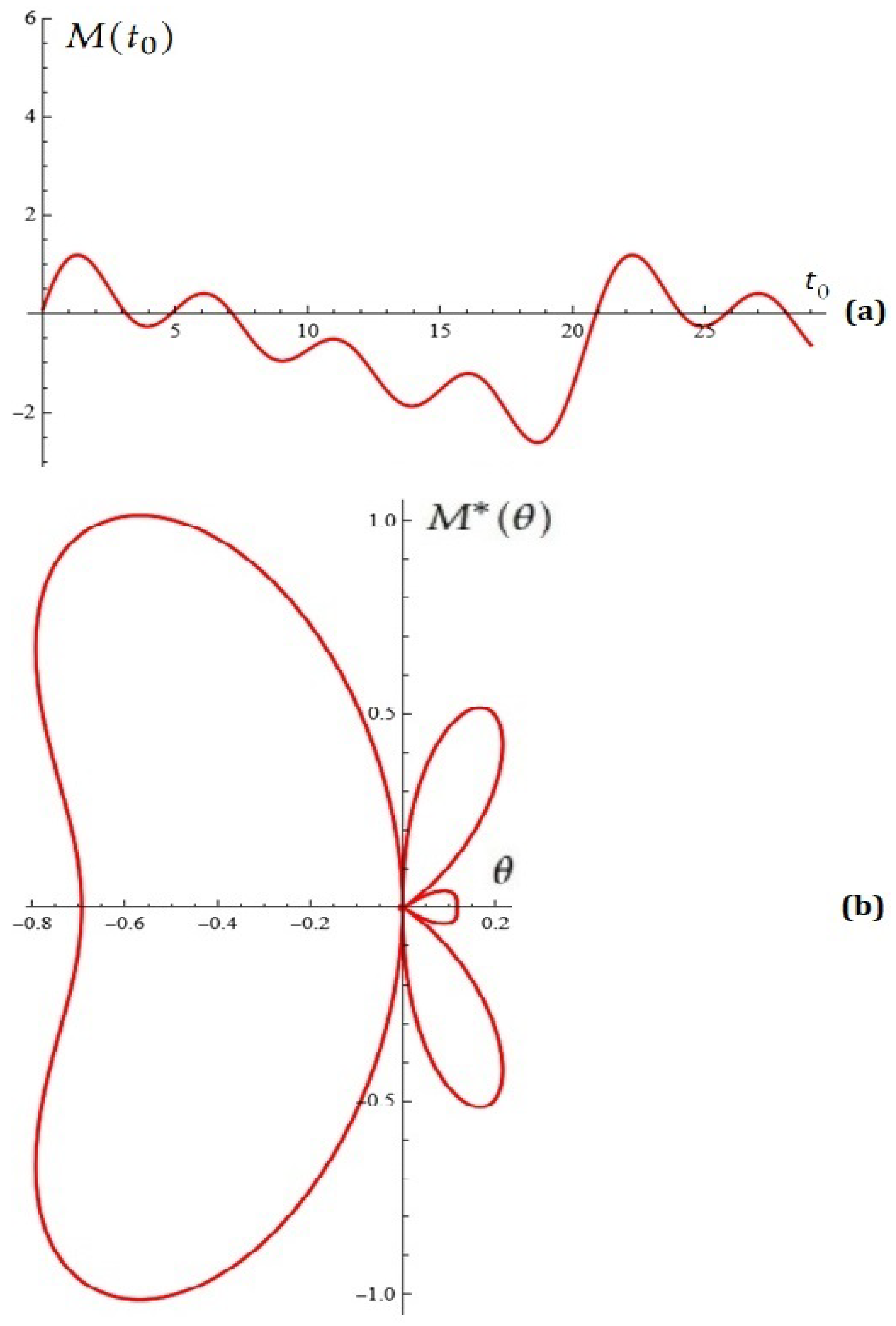
Let us fix N = 4 , k = 0.05 , ω = 0.3 , ρ 0 = 0.25 , ρ = 0.2 , ρ 1 = 0.1 , ρ 2 = 0.05 , ρ 3 = 0.05 , ρ 4 = 0.1 , K = 4 , k 2 = 0 .
Melnikov function M ( t 0 ) is depicted in Figure 10a. The Melnikov antenna factor is depicted in Figure 10b.
Example 5.
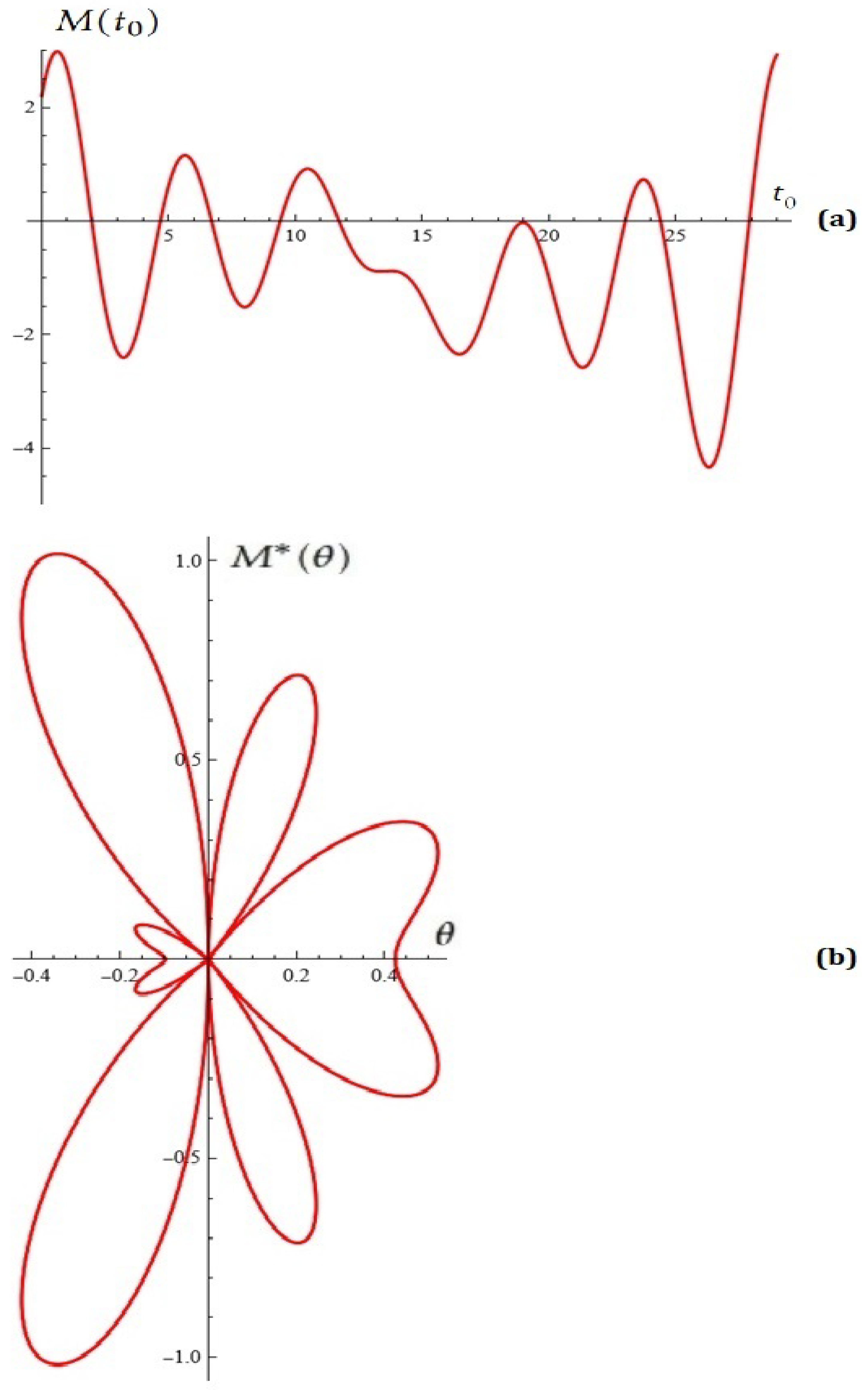
Let us fix N = 6 , k = 0.17 , ω = 0.22 , ρ 0 = 0.25 , ρ = 0.15 , ρ 1 = 0.1 , ρ 2 = 0.005 , ρ 3 = 0.16 , ρ 4 = 0.11 , ρ 5 = 0.6 , ρ 6 = 0.9 K = 4.6 , k 2 = 0.7 .
Melnikov function M ( t 0 ) is depicted in Figure 11a. The Melnikov antenna factor is depicted in Figure 11b.
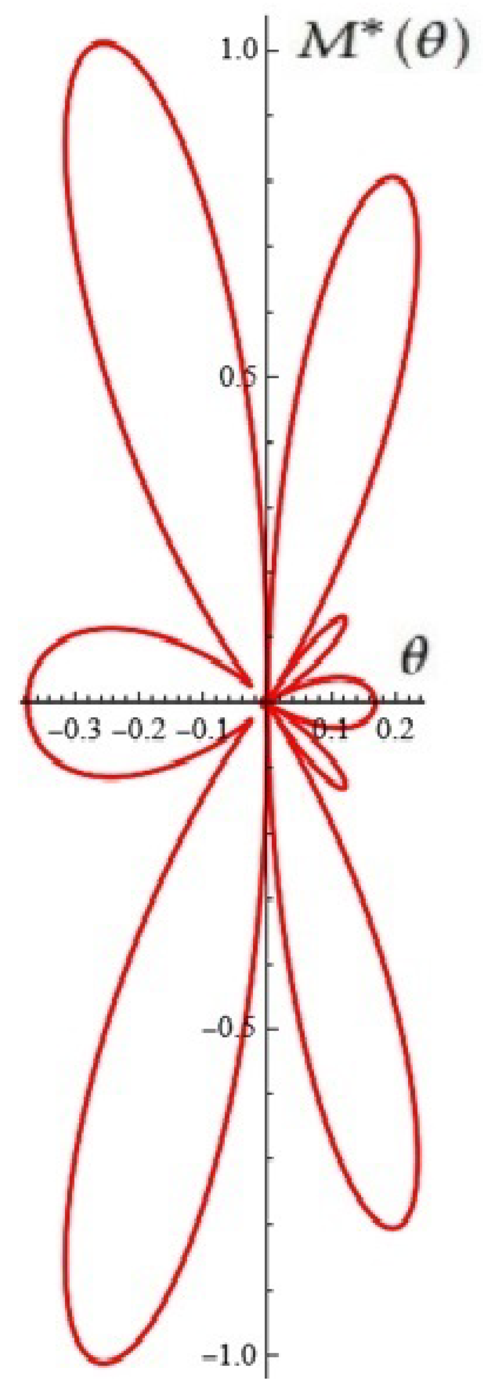
It is easy to see that the Melnikov polynomial M ( t 0 ) from Example 3 (see Figure 8) for K = 8.6 , k 2 = 0 generates the Melnikov antenna factor depicted in Figure 12.
Remark 3.
Of course, it remains an open question whether such diagrams can be practically realized.

3. Using Stochastic Construction to Potentially Control Oscillations

The job of creating a probabilistic structure in order to potentially control the oscillations of the dynamic model suggested in this article is very intriguing. The reasons for this are as follows: The important features of model (2) are that we can control jointly the amplitude of the oscillations through the parameters ρ j and their frequencies through the multiplication by j in the sin-function. In this light, if we sum all ρ j , then ρ ¯ = j = 1 N ρ j and ρ ¯ j = ρ j ρ ¯ can be viewed as the total amplitude and the proportions between the different frequency factors. The idea that stands behind our suggestion for using probability distributions to control the oscillations has two very significant advantages. First, we can use not only natural numbers for the frequency’s orders but arbitrary subsets of the real numbers. But more important is that we can set the total amplitude as well as the proportions between all frequencies by appropriate choice of the distribution. For example, the uniform distribution on some interval leads to equal proportions of the frequency factors with sizes in this interval. On the other hand, the normal distribution gives the whole real line for the frequency order—more weights have the terms in the center, whereas the others follow the specific Gaussian structure. Furthermore, the light tails of the normal distribution lead to a negligible impact of the orders that are far from the center. Alternatively, we can use distributions with heavy or fat tails (stable, tempered stable, etc.) to strengthen the impact of the frequencies that stand far from the center. In addition, we can choose symmetric, asymmetric, multimodal, mixture, etc., distributions to capture the desired structure of the periodic term in the oscillator.
Suppose that ρ ¯ = j = 1 N ρ j and ρ ¯ j = ρ j ρ ¯ . Having in mind that j = 1 N ρ ¯ j = 1 , we view the coefficients ρ ¯ j as probabilities of a random variable ζ to achieve values 1 , 2 , , N . Let its characteristic function be denoted by ψ x . Using the exponential form of the sin-function, written as follows:
sin x = e i x e i x 2 i ,
we rewrite the y-dynamics of model (2) as
d y d t = sin x k y 2 + ρ 0 + ϵ ρ ρ 0 + j = 1 N ρ j sin ( j ω t ) = sin x k y 2 + ρ 0 + ϵ ρ ρ 0 + ρ ¯ j = 1 N ρ ¯ j sin ( j ω t ) = sin x k y 2 + ρ 0 + ϵ ρ ρ 0 + ρ ¯ j = 1 N ρ ¯ j e i j ω t e i j ω t 2 i = sin x k y 2 + ρ 0 + ϵ ρ ρ 0 + ρ ¯ ψ ω t ψ ω t 2 i .
This formulation shows that we can leave the assumption that the random variable ζ is stated on the discrete support 1 , 2 , , N . If we suppose that its domain is D, then model (2) can be written as follows:
d x d t = y d y d t = sin x k y 2 + ρ 0 + ϵ ρ ρ 0 + ρ ¯ D sin ( u ω t ) ν d y sin x k y 2 + ρ 0 + ϵ ρ ρ 0 + ρ ¯ ψ ω t ψ ω t 2 i ,
where ν d y defines the distribution of ζ .
We shall present two examples based on a μ , σ -Gaussian distribution and a continuous uniform one supported on the interval 0 , 1 . Thus the domains are D = , and D = 0 , 1 , respectively. Their probability density functions are as follows:
f G a u s s i a n x = 1 2 π σ 2 e x μ 2 2 σ 2 f u n i f o r m x = 1 .
Furthermore, the characteristic functions of these distributions are as follows:
ψ G a u s s i a n x = e i μ x σ 2 x 2 2 ψ u n i f o r m x = e i x 1 i x .
We can easily check that the following relations hold:
ψ G a u s s i a n x ψ G a u s s i a n x = 2 i e σ 2 x 2 2 sin μ x ψ u n i f o r m x ψ u n i f o r m x = 2 i 1 cos x x .
Thus, in the Gaussian case, model (2) can be written as follows:
d x d t = y d y d t = sin x k y 2 + ρ 0 + ϵ ρ ρ 0 + ρ ¯ e σ 2 ω 2 t 2 2 sin μ ω t ,
whereas for the uniform distribution, we have
d x d t = y d y d t = sin x k y 2 + ρ 0 + ϵ ρ ρ 0 + ρ ¯ 1 cos ω t ω t .
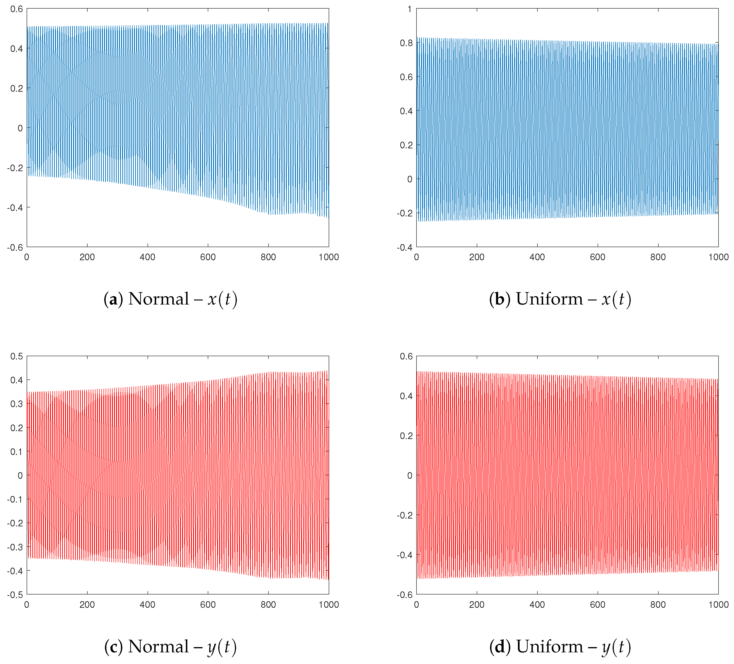
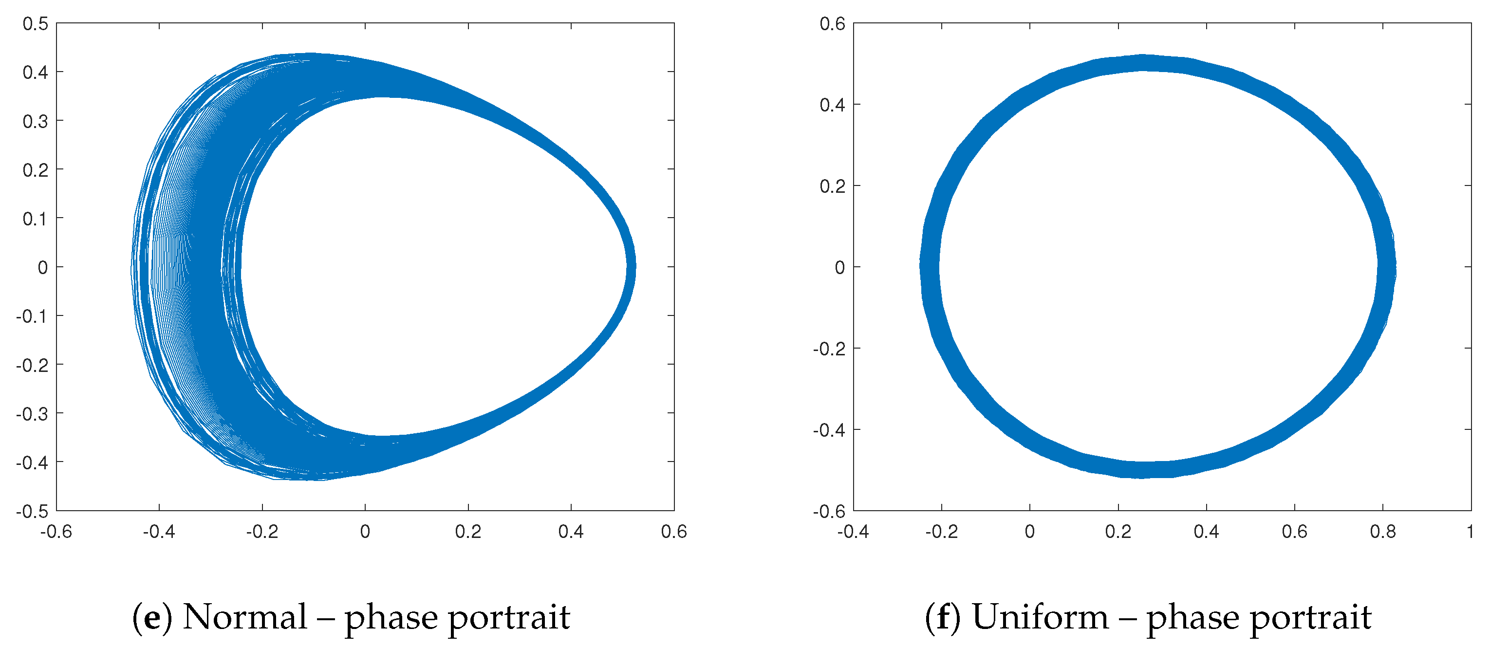
In Figure 13, we present some simulations for both models. The used parameters are ρ 0 = 0.3 , ρ = 0.2 , ρ ¯ = 3.3 , ϵ = 0.015 , ω = 10 , k = 2.15 , x ( 0 ) = 0.2 , and y ( 0 ) = 0.2 . The Gaussian distribution is with parameters μ = 0.1 and σ = 1 .
The Melnikov integral given by Formula (4) now takes the following form:
M G a u s s i a n t 0 = b sech b ( t t 0 ) 2 ρ ρ 0 + ρ ¯ e σ 2 ω 2 t 2 2 sin μ ω t e 0 t t 0 2 k b sech b t 2 d t d t M u n i f o r m t 0 = b sech b ( t t 0 ) 2 ρ ρ 0 + ρ ¯ 1 cos ω t ω t e 0 t t 0 2 k b sech b t 2 d t d t .

4. Conclusions

In this article, we study prediction of chaos in a N-generalized Josephson junction with quadratic damping by the Melnikov technique.
The introduction of a multi-frequency perturbation term ( A i sin ( i ω t ) ) in Equation (2) is a non-trivial and valuable generalization of the standard model found in the literature. This allows for a richer analysis of chaos and is a contribution.
A number of simulations are created. We also show off a few specific modules for examining the model’s behavior.
There is also discussion of one use for potential oscillation control.
The new model is appealing for engineering calculations because it contains a lot of free parameters.
The suggested extended model is particularly helpful in the antenna array theory, a crucial area of decision-making.
This is because high-order Melnikov polynomials and the Melnikov antenna factors that go along with them can be generated.
We will explicitly note that the reader can consider models with “strong damping” of the following type:
d x d t = y d y d t = sin x c x d y ϵ i = 1 N g i cos ( ω t )
and based on the research in [13] and the present article to explore their dynamics. We will not dwell on these issues here.
In the planned (by us) web-based application [40] a specialized module has been developed and implemented in CAS Mathematica for generating a Melnikov antenna factor.
We will explicitly note that the generalized differential model considered in this article is at this stage only a hypothetical model until specialists working in the field of engineering sciences decide on its right to exist.
We note that Examples 1 and 2 are study examples. Making contemporary GPT technologies—which students heavily rely on to complete their scientific assignments—as challenging as possible is the main goal.
If this article sparks an intriguing conversation regarding the teaching approach in this area of scientific knowledge, we will be happy.

Author Contributions

Conceptualization, N.K. and T.Z.; methodology, N.K. and T.Z.; software, V.K., T.Z., A.I. and A.R.; validation, A.I., N.K., V.K. and T.Z.; formal analysis, T.Z. and N.K.; investigation, V.K., N.K., T.Z., A.R. and A.I.; resources, V.K., A.I., A.R., T.Z. and N.K.; data curation, A.R., A.I., T.Z. and N.K.; writing—original draft preparation, N.K., T.Z., A.I. and V.K.; writing—review and editing, T.Z., N.K., A.I., V.K. and A.R.; visualization, V.K., A.I., T.Z., and N.K.; supervision, T.Z. and N.K.; project administration, T.Z. and N.K.; funding acquisition, N.K., A.I., T.Z. and A.R. All authors have read and agreed to the published version of the manuscript.

Funding

The work was supported by the Centre of Excellence in Informatics and ICT under grant No. BG16RFPR002-1.014-0018-C01, financed by the Research, Innovation and Digitalization for Smart Transformation Programme 2021-2027, and co-financed by the European Union.

Institutional Review Board Statement

Not applicable.

Informed Consent Statement

Not applicable.

Data Availability Statement

Data are contained within the article.

Conflicts of Interest

The authors declare no conflicts of interest.

References

  1. Jaklevic, R.C.; Lambe, J.; Silver, A.H.; Mercereau, J.E. Quantum Interference Effects in Josephson Tunneling. Phys. Rev. Lett. 1964, 12, 159–160. [Google Scholar] [CrossRef]
  2. Clarke, J.; Braginski, A.I. (Eds.) The SQUID Handbook: Fundamentals and Technology of SQUIDs and SQUID Systems; Wiley-VCH: Weinheim, Germany, 2004; Volume 1. [Google Scholar]
  3. Clarke, J.; Braginski, A.I. (Eds.) The SQUID Handbook: Applications of SQUIDs and SQUID Systems; Wiley-VCH: Weinheim, Germany, 2006; Volume 2. [Google Scholar]
  4. Ritala, R.K.; Salomaa, M.M. Odd and even subharmonics and chaos in RF SQUIDS. J. Phys. C Solid State Phys. 1983, 16, 477–484. [Google Scholar] [CrossRef]
  5. Ritala, R.K.; Salomaa, M.M. Chaotic dynamics of periodically driven rf superconducting quantum interference devices. Phys. Rev. B 1984, 29, 6143–6154. [Google Scholar] [CrossRef]
  6. Fesser, K.; Bishop, A.R.; Kumar, P. Chaos in rf SQUID’s. Appl. Phys. Lett. 1983, 43, 123–124. [Google Scholar] [CrossRef]
  7. Schieve, W.C.; Bulsara, A.R.; Jacobs, E.W. Homoclinic chaos in the rf superconducting quantum-interference device. Phys. Rev. A 1988, 37, 3541–3552. [Google Scholar] [CrossRef] [PubMed]
  8. Ling, F.H.; Bao, G. A numerical implementation of Melnikov’s method. Phys. Lett. A 1987, 122, 413–417. [Google Scholar] [CrossRef]
  9. Salam, F.M.A. The Mel’nikov technique for highly dissipative systems. SIAM J. Appl. Math. 1987, 47, 232–243. [Google Scholar] [CrossRef]
  10. Schecter, S. Melnikov’s method at a saddle–node and the dynamics of the forced Josephson junction. SIAM J. Math. Anal. 1987, 18, 1699–1715. [Google Scholar] [CrossRef]
  11. Grebogi, C.; Ott, E.; Yorke, J.A. Basin boundary metamorphoses: Changes in accessible boundary orbits. Phys. D 1987, 24, 243–262. [Google Scholar] [CrossRef]
  12. Bruhn, B.; Koch, B. Homoclinic and Heteroclinic Bifurcations in rf SQUIDs. Z. Naturforsch. A 1988, 43, 930–938. [Google Scholar] [CrossRef]
  13. Kyurkchiev, N.; Zaevski, T.; Iliev, A.; Branzov, T. A Note on the Dynamics of Modified rf-SQUIDs: Simulations and Possible Control over Oscillations. Mathematics 2025, 13, 722. [Google Scholar] [CrossRef]
  14. Falko, C.; Parker, W. Operating characteristics of thin-film rf-biased SQUID’s. J. Appl. Phys. 1975, 46, 3238–3243. [Google Scholar] [CrossRef]
  15. Zhang, Y.; Muck, M.; Braginski, A.I.; Topfer, H. High-sensitivity microwave rf SQUID operating at 77 K. Supercond. Sci. Technol. 1994, 7, 269–272. [Google Scholar] [CrossRef]
  16. Zhang, Y.; Muck, M.; Herrmann, K.; Schubert, J.; Zander, W.; Braginski, A.I.; Heiden, C. Sensitive rf SQUIDs and magnetometers operating at 77 K. IEEE Trans. Appl. Supercond. 1993, 3, 2465–2468. [Google Scholar] [CrossRef]
  17. Il’ichev, E.; Zakosarenko, V.; Ijsselsteijn, R.P.; Schultze, V. Inductive reply of high-Tc rf SQUID in the presence of large thermal fluctuations. J. Low Temp. Phys. 1997, 106, 503–508. [Google Scholar] [CrossRef]
  18. Chesca, B. On the theoretical study of an rf-SQUID operation taking into account the noise influence. J. Low Temp. Phys. 1994, 94, 515–538. [Google Scholar] [CrossRef]
  19. Greenberg, Y. Signal characteristics for high Tc rf SQUID from its small signal voltage-frequency characteristics. J. Low Temp. Phys. 1998, 114, 297–316. [Google Scholar] [CrossRef]
  20. Jeanneret, B.; Benz, S.P. Application of the Josephson effect in electrical metrology. Eur. Phys. J. Spec. Top. 2009, 172, 181–206. [Google Scholar] [CrossRef]
  21. Martínez-Pérez, M.J.; Koelle, D. NanoSQUIDs: Basics and recent advances. Phys. Sci. Rev. 2017, 2, 20175001. [Google Scholar] [CrossRef]
  22. Tarte, E.J.; Moseley, R.W.; Kölbl, M.R.; Booij, W.E.; Burnell, G.; Blamire, M.G. Asymmetry modulated SQUIDS. Supercond. Sci. Technol. 2000, 13, 983–988. [Google Scholar] [CrossRef]
  23. Likharev, K.K.; Semenov, V.K. RSFQ logic/memory family: A new Josephson-junction technology for sub-terahertz-clock-frequency digital systems. IEEE Trans. Appl. Supercond. 1991, 1, 3–28. [Google Scholar] [CrossRef]
  24. Soloviev, I.I.; Klenov, N.V.; Bakurskiy, S.V.; Kupriyanov, M.Y.; Gudkov, A.L.; Sidorenko, A.S. Beyond Moore’s technologies: Operation principle of a superconductor alternative. Beilstein J. Nanotechnol. 2017, 8, 2689–2710. [Google Scholar] [CrossRef] [PubMed]
  25. Vitanov, N.; Martinov, N. On the solitary waves in the sine-Gordon model of the two-dimensional Josephson junction. Z. Phys. B Condens. Matter 1996, 100, 129–135. [Google Scholar] [CrossRef]
  26. Guckenheimer, J.; Holmes, P. Nonlinear Oscillations, Dynamical Systems, and Bifurcations of Vector Fields; Springer: New York, NY, USA, 1983. [Google Scholar]
  27. Wiggins, S. Global Bifurcations and Chaos; Springer: New York, NY, USA, 1988. [Google Scholar]
  28. Chacon, R. Control of Homoclinic Chaos by Weak Periodic Perturbations; World Scientific Series of Nonlinear Science; World Scientific Publishing Co. Pte. Ltd.: Singapore, 2005; Volume 55. [Google Scholar]
  29. Braiman, Y.; Goldhirsch, I. Taming chaotic dynamics with weak periodic perturbations. Phys. Rev. Lett. 1991, 66, 2545–2548. [Google Scholar] [CrossRef]
  30. Ostrovskii, V.; Karimov, A.; Rybin, V.; Kopets, E.; Butusov, D. Comparing the Finite-Difference Schemes in the Simulation of Shunted Josephson Junctions. In Proceedings of the 23rd Conference of Open Innovations Association (FRUCT), Bologna, Italy, 13–16 November 2018; pp. 300–305. [Google Scholar]
  31. Salam, F.M.A.; Sastry, S.S. The complete dynamics of the forced Josephson junction circuit-The regions of chaos. In Chaos in Nonlinear Dynamical Systems; Chandra, J., Ed.; Society for Industrial and Applied Mathematics: Philadelphia, PA, USA, 1984; pp. 43–55. [Google Scholar]
  32. Cveticanin, L.; Herisanu, N.; Ninkov, I.; Jovanovic, M. New Closed-Form Solution for Quadratic Damped and Forced Nonlinear Oscillator with Position-Dependent Mass: Application in Grafted Skin Modeling. Mathematics 2022, 10, 2706. [Google Scholar] [CrossRef]
  33. Bartuccelli, M.; Christiansen, P.L.; Pedersen, N.F.; Sørensen, M.P. Prediction of chaos in a Josephson junction by the Melnikov-function technique. Phys. Rev. B 1986, 33, 4686–4691. [Google Scholar] [CrossRef]
  34. Melnikov, V.K. On the stability of the center for time periodic perturbations. Trans. Mosc. Math. Soc. 1963, 12, 3–52. [Google Scholar]
  35. Pedersen, N.F.; Saermark, K. Analytical solution for a Josephson-Junction model with capacitance. Physica 1973, 69, 572–578. [Google Scholar] [CrossRef]
  36. Makrelov, I.; Kyurkchiev, N.; Tamburov, S. Two two-sided methods for simultaneous determination of all roots of trigonometric and exponential polynomials. Trav. Sci. Univ. Plovdiv Math. 1985, 23, 289–298. [Google Scholar]
  37. Proinov, P.; Cholakov, S.; Vasileva, M. Fully Computable Convergence Analysis of a Fourth Order Iterative Method for Finding Polynomial Roots. J. Appl. Math. Comput. 2025, 71, 6365–6380. [Google Scholar] [CrossRef]
  38. Marcheva, P.I.; Ivanov, I.K.; Ivanov, S.I. On the Q-Convergence and Dynamics of a Modified Weierstrass Method for the Simultaneous Extraction of Polynomial Zeros. Algorithms 2025, 18, 205. [Google Scholar] [CrossRef]
  39. Sendov, B.; Andreev, A.; Kyurkchiev, N. Numerical solution of polynomial equations. In Handbook of Numerical Analysis; Ciarlet, P.G., Lions, J.L., Eds.; Elsevier Science Publ.: Amsterdam, The Netherlands, 1994; Volume III, pp. 625–778. [Google Scholar]
  40. Golev, A.; Terzieva, T.; Iliev, A.; Rahnev, A.; Kyurkchiev, N. Simulation on a Generalized Oscillator Model: Web-Based Application. Comptes Rendus Acad. Bulg. Sci. 2024, 77, 230–237. [Google Scholar] [CrossRef]
  41. Georgieva, M.; Grozdev, S. Morphodynamics for the Development of Noospheric Intelligence; East-West Publishing House: Sofia, Bulgaria, 2016. (In Bulgarian) [Google Scholar]
  42. Dolph, C.L. A Current Distribution for Broadside Arrays which Optimizes the Relationship between Beam Width and Side-Lobe Level. Proc. IRE 1946, 34, 335–348. [Google Scholar] [CrossRef]
  43. Tu, L.; Ng, B.P. Exponential and generalized Dolph - Chebyshev functions for flat-top array beam pattern synthesis. Multidimens. Syst. Signal Process. 2013, 25, 541–561. [Google Scholar] [CrossRef]
  44. Hutu, F.; Cauet, S.; Coirault, P. Antenna Arrays Principle and Solutions: Robust Control Approach. Int. J. Comput. Commun. Control 2008, 3, 161–171. [Google Scholar] [CrossRef]
  45. Iordache, M.; Paillot, J.M.; Dumitrescu, I.; Ionita, M. Analysis of Coupled Oscillators Applied to Antenna Arrays. Ann. Univ. Craiova Electr. Eng. Ser. 2010, 34, 1–10. [Google Scholar]
  46. Kyurkchiev, N.; Zaevski, T.; Iliev, A.; Kyurkchiev, V.; Rahnev, A. Studying homoclinic chaos in a class of piecewise smooth oscillators: Melnikov’s approach, symmetry results, simulations and applications to generating antenna factors using approximation and optimization techniques. Symmetry 2025, 17, 1144. [Google Scholar] [CrossRef]
  47. Apostolov, P.; Valchev, D.G. Closed-Form Expressions for Half Power Beam Width and Steering of Two-Dimensional Rectangular Binomial Array Antenna. In Proceedings of the 2024 15th National Conference with International Participation (ELECTRONICA), Sofia, Bulgaria, 16–17 May 2024; pp. 1–4. [Google Scholar]
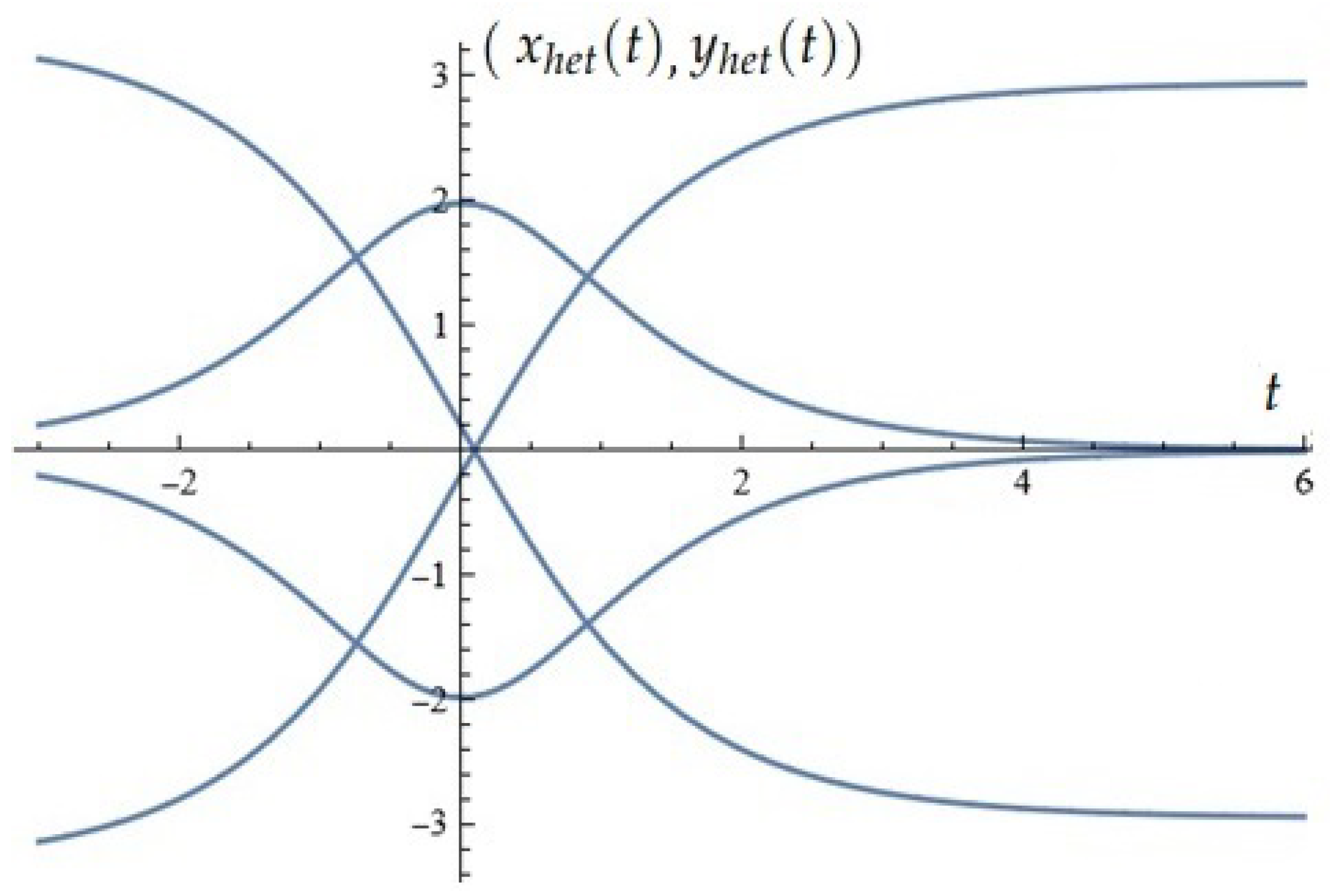
Figure 1. Heteroclinic orbits for k = 0.1 ; ρ 0 = 0.396 ; b = 1.9797 ; β = 0.197396 .
Applsci 15 12359 g001
Figure 5. (a) x-component of the solutions of the system (2); (b) y-component of the solutions of the system (2); (c) phase space (Example 1).
Applsci 15 12359 g005
Figure 6. (a) x-component of the solutions of the system (2); (b) y-component of the solutions of the system (2); (c) phase space (Example 2).
Applsci 15 12359 g006
Figure 7. (a) x-component of the solutions of the system (2); (b) y-component of the solutions of the system (2); (c) phase space (Example 3).
Applsci 15 12359 g007
Figure 8. Melnikov function M ( t 0 ) : Task 1.
Applsci 15 12359 g008
Figure 9. (a) x-component of the solutions of the system (2); (b) y-component of the solutions of the system (2); (c) phase space (Task 2).
Applsci 15 12359 g009
Figure 10. (a) Melnikov function M ( t 0 ) (Example 3); (b) Melnikov antenna factor (Example 4).
Applsci 15 12359 g010
Figure 11. (a) Melnikov function M ( t 0 ) (Example 4); (b) Melnikov antenna factor (Example 5).
Applsci 15 12359 g011
Figure 12. Melnikov antenna factor (Example 3).
Applsci 15 12359 g012
Figure 13. Dynamics.
Applsci 15 12359 g013aApplsci 15 12359 g013b
Disclaimer/Publisher’s Note: The statements, opinions and data contained in all publications are solely those of the individual author(s) and contributor(s) and not of MDPI and/or the editor(s). MDPI and/or the editor(s) disclaim responsibility for any injury to people or property resulting from any ideas, methods, instructions or products referred to in the content.