Article

Research on the Stability of Tailings Dams Under the Combined Stacking of Waste Rock Pillars and Tailings

1
Faculty of Land Resources Engineering, Kunming University of Science and Technology, Kunming 650093, China
2
Kunming Nonferrous Metals Design & Research Institute Co., Ltd., Kunming 650091, China
*
Author to whom correspondence should be addressed.
Appl. Sci. 2025, 15(23), 12348; https://doi.org/10.3390/app152312348
Submission received: 21 October 2025 / Revised: 17 November 2025 / Accepted: 19 November 2025 / Published: 21 November 2025
(This article belongs to the Topic Sustainable Environmental Technologies—2nd Edition)

Abstract

Tailings dam failures are often caused by seepage, posing severe threats to mine safety and downstream ecological environments. Conventional tailings stacking methods are prone to drainage blockage and slope instability under long-term seepage conditions. To address this issue, this study proposes a novel structural form that combines waste rock pillars with tailings stacking to construct a drainage system characterized by high permeability, anti-clogging capability, and load-bearing performance. A prototype-similar physical model test was conducted to systematically analyze the seepage characteristics and stability variations in the tailings dam under different dry beach lengths. In addition, numerical simulations using Geo-Studio 2022.1 (SEEP/W and SLOPE/W) were performed to verify and extend the experimental results. The findings show that the introduction of waste rock pillars forms effective preferential drainage channels, significantly reduces pore water pressure, and lowers the phreatic line within the dam body, thereby enhancing its overall stability. Compared with the conventional stacking method without waste rock pillars, the safety factor of the dam increased by 8.6–20.0% as the dry beach length extended from 70 m to 150 m, confirming the remarkable reinforcement and drainage performance of the composite structure. The study demonstrates that the proposed “high-permeability, anti-clogging, and load-bearing” waste rock pillar design not only achieves efficient reuse of waste rock resources but also provides a novel and sustainable technical approach for improving tailings dam safety through coupled physical and numerical verification.

1. Introduction

The tailings dam is the peripheral structure of a tailings storage facility. It not only serves to retain tailings and water but also constitutes an indispensable component of the tailings storage facility [1]. With the increasing demand for mineral resources in China, both the number and scale of tailings storage facilities have expanded continuously. As the phreatic line of a tailings dam represents its safety boundary [2], reducing this line through various drainage facilities plays a crucial role in enhancing dam safety.
The permeability and drainage performance of tailings materials directly affect the phreatic line and overall dam stability. Previous studies have indicated that optimizing internal drainage structures or incorporating coarse-grained materials can effectively reduce pore water pressure and improve dam safety under long-term seepage conditions [3]. Tailings dam drainage facilities, such as radial collection wells, drainage pipelines, and drainage walls, have been increasingly adopted due to their relatively simple principles, reliable structures, and efficient management [4,5,6]. The commonly used drainage pipes are composed of polyvinyl chloride (PVC) pipes wrapped with geotextile fabric. However, such drainage pipes exhibit performance limitations in practice [7], as their seepage capacity is mainly constrained by the perforated area; consequently, their drainage efficiency is relatively inadequate under high-permeability requirements. In addition, factors such as pore size distribution, permeability of the geotextile, and installation conditions also affect its drainage performance [8,9,10]. The geotextile serves a filtration function within the drainage system by preventing fine tailings particles from entering the pipe openings [11]. Meanwhile, Wu Haimin et al. [12] experimentally investigated the permeability of three different geotextile filter layers, and the results demonstrated that geotextiles possess excellent anti-clogging properties. Research by Du et al. [13] indicates that geogrid reinforcement can effectively lower the seepage line within the dam body. Liu et al. [14] proposed that a system combining horizontal and upward-curved drainage pipes can reduce seepage pressure within the dam body. Subsequently, the external lattice mesh technology [15] was introduced to enhance the seepage capacity of drainage pipes by increasing their equivalent perforation area. This composite drainage pipe has been applied to the crest of the initial dam [16], arranged in a single horizontal row [17]. Experimental and numerical results have confirmed that this configuration effectively lowers the phreatic line within the dam body. Traditional drainage systems, such as gravel drains or PVC perforated pipes, often suffer from clogging and structural degradation during operation, which limits their long-term efficiency [18].To address this issue, several researchers have explored the use of waste rock or other coarse materials to form preferential drainage zones within tailings deposits, showing improved seepage control and shear resistance compared with conventional designs [19]. Existing studies still present certain limitations, as the seepage capacity remains constrained by the perforation area. During long-term operation, drainage pipes are also prone to clogging, which reduces drainage efficiency. Moreover, the transportation of large quantities of waste rock generated during mining operations increases overall operating costs. Furthermore, the coupled physical–numerical approaches have provided new insights into the evolution of seepage fields and stability behavior of composite tailings structures, emphasizing the importance of considering material heterogeneity and dynamic hydraulic responses [20]. Nevertheless, most existing studies have focused either on fine tailings systems or homogeneous drainage media, while the application of waste rock pillars as a structured drainage and reinforcement component within tailings dams has rarely been reported in the literature.
This study aims to address this research gap by proposing a composite pile design combining waste rock pillars and tailings. This structure is designed to create a drainage system that combines high permeability, anti-clogging properties, and load-bearing capacity [21]. The waste rock pillar consists of an outer layer wrapped with stainless-steel wire mesh and geotextile, filled internally with waste rock. Its main features include an enlarged seepage area, enhanced anti-clogging capability, and an increased drainage path within the tailings dam. This study systematically investigated the influence of waste rock pillars on the drainage capacity and stability of tailings dams by selecting dry beach length as the control variable, with mutual validation through physical model tests and numerical simulations. Given that tailings ponds may serve as artificial debris flow sources with high potential energy, a tailings dam failure could pose a severe threat to downstream lives and property. Therefore, researching new methods for combined waste rock and tailings placement holds significant importance [19,22,23].

2. Physical Model Testing of Waste Rock Pillars

2.1. Project Overview

To verify the seepage behavior and stability of the proposed waste rock pillar–tailings co-deposition structure, a physical model test was first conducted. The case study is located in Yunnan Province and adopts the upstream dam construction method. The project commenced with an initial dam crest elevation of 1796.0 m and was constructed in successive stages, ultimately reaching the designed elevation of 1840.0 m. The embankment dam reaches a height of 44 m, with the total dam height, including the initial dam structure, amounting to 64.5 m. The embankment dam was designed with a stable slope ratio of 1:4.0. The construction process strictly adhered to the technical specifications for stepped embankment placement. Each sub-dam was vertically stacked to a height of 2.0 m, with a 4.0 m wide access ramp installed. When the designed elevation of 1840.0 m is reached, the total storage capacity of the tailings reservoir is 8.36 million m3, of which the effective capacity is 7.108 million m3. This tailings dam was selected as the study site due to its distinct dry beach, thick fine-grained tailings layer, and persistent drainage issues, which fully exemplify the seepage and stability concerns addressed in this research. The site conditions provide an ideal foundation for validating the proposed waste rock pillar design through both physical and numerical analysis. The test material consisted of full tailings samples collected from the concentrator of the same tailings storage facility (Figure 1).

2.2. Model Test Design and Process

Physical model tests will be conducted based on the aforementioned project background. The specific model will be designed using similarity theory to analyze the tailings dam’s similarity ratio. Considering laboratory testing conditions, a geometric similarity ratio of 1:200 will be adopted [24,25], with other parameters as shown in Table 1.
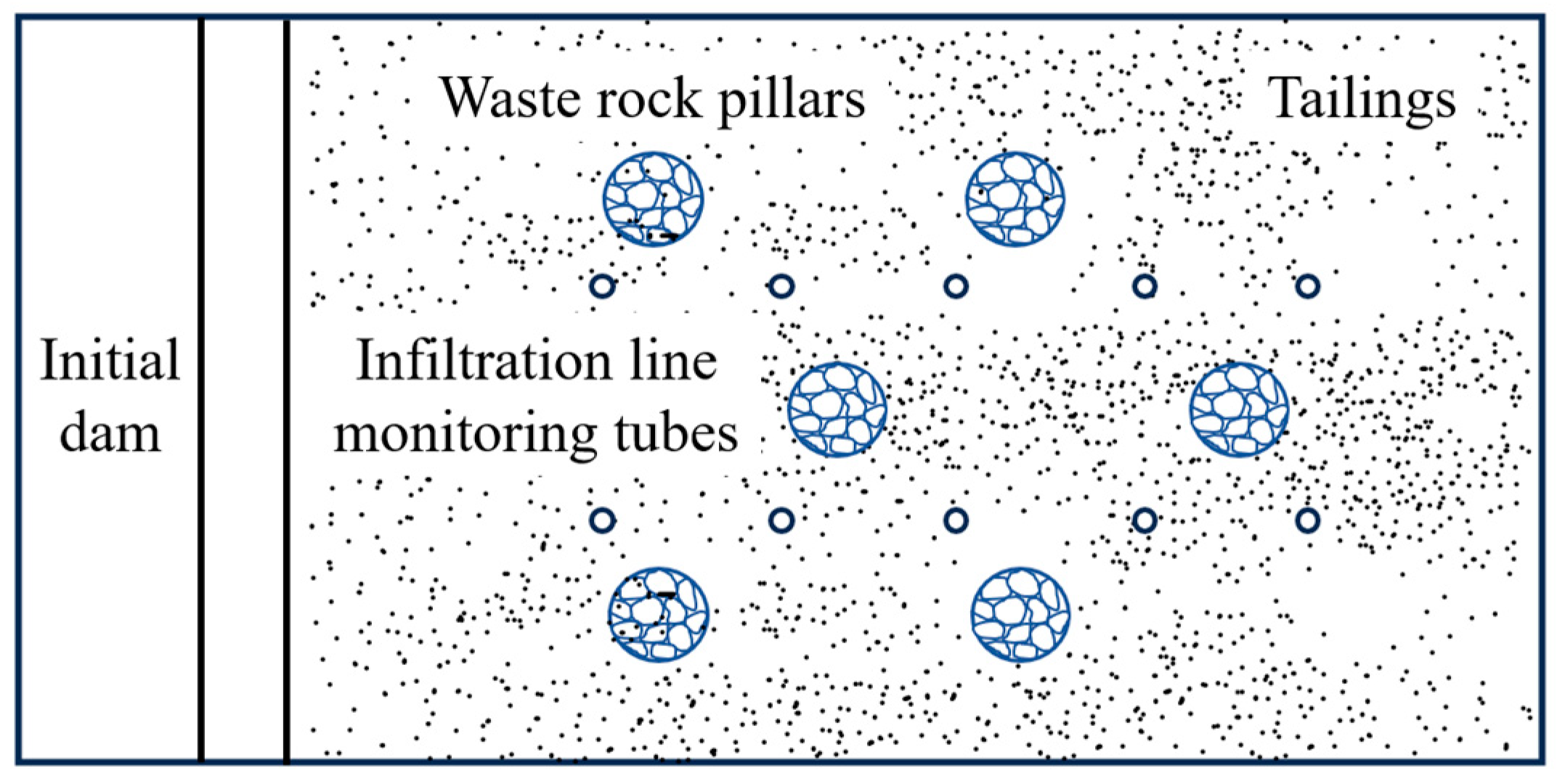
In the experiment, the masses of tailings and water were measured to prepare a tailings slurry of specific concentration based on the proportion collected from the field, which was then discharged into the tailings storage facility through the tailings discharge system. Five rows comprising ten phreatic line monitoring pipes were arranged along the central axis of the model, with two monitoring pipes installed on each cross-section (as shown in Figure 2). The phreatic line monitoring data were obtained using the mean value method. The monitoring pipe system was arranged in a grid pattern from the initial dam toward the interior of the reservoir and numbered according to the “row–pipe” scheme (e.g., the two pipes in the first row were numbered 1–1 and 1–2). A total of four rows comprising six waste rock pillars were installed within the reservoir, arranged in a “plum-blossom” pattern. Control valves were used to precisely regulate the drainage system of the waste rock pillars, enabling dynamic monitoring of seepage flow.
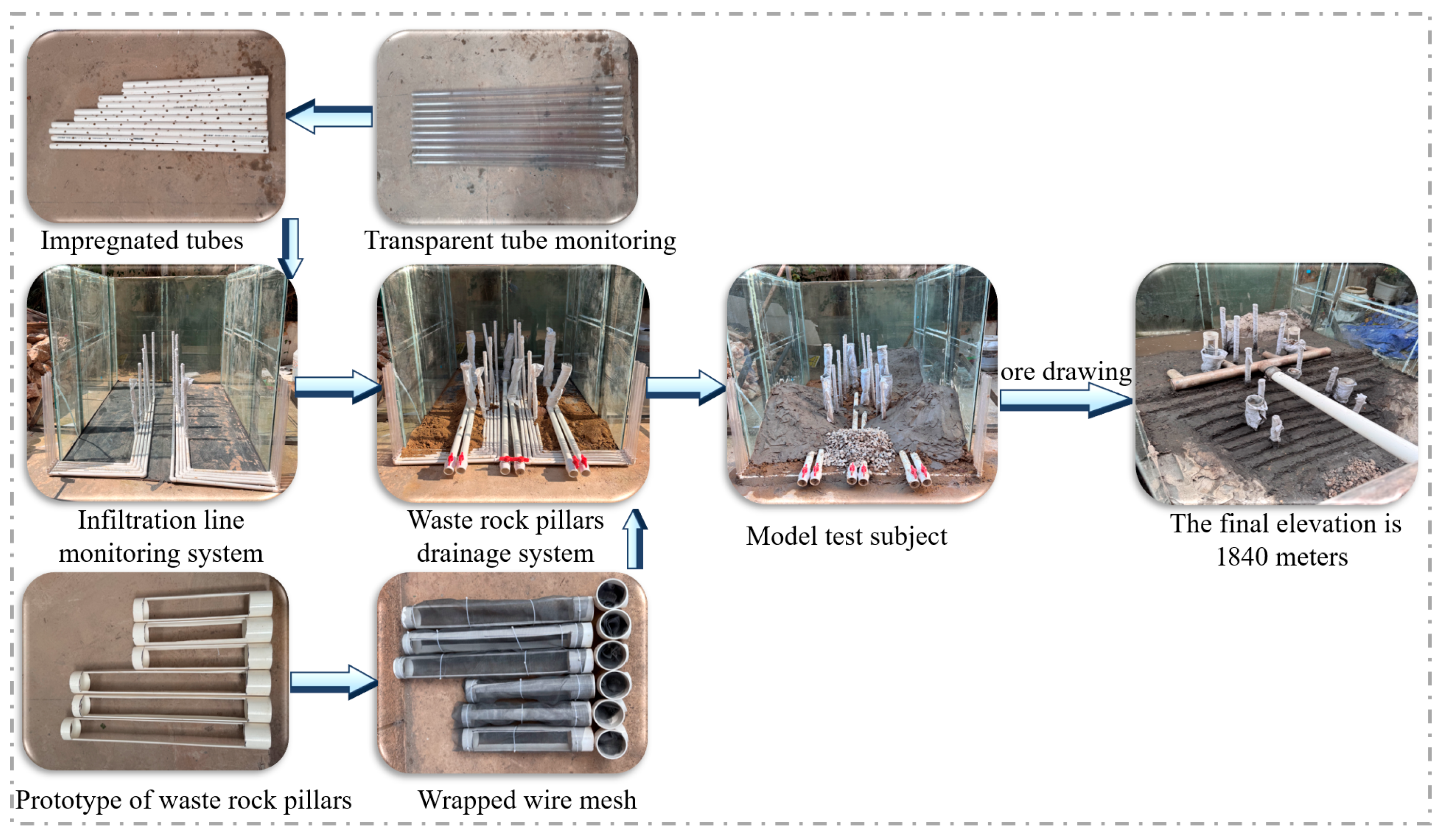
The tailings reservoir model tank was assembled using a three-section glass structure. Its terrain was proportionally shaped with engineering clay to replicate the actual topographic features of the tailings storage area, while the initial dam structure was constructed by stacking well-graded crushed stone mixtures. The waste rock pillar structure used a PVC drainage pipe with an outer diameter of 75 mm as the core component. It was externally wrapped with a stainless-steel woven wire mesh and a geotextile filter layer to form a composite protective system, while the interior was filled with well-graded waste rock to create a drainage skeleton framework. A stainless-steel wire mesh interception structure was installed at the bottom of the drainage pipe to effectively prevent blockage caused by the migration of the graded waste rock material. The drainage system was connected to the external drainage network through a 50 mm non-perforated PVC diversion pipe, with control valves installed to achieve precise regulation of the discharge from the waste rock pillars.
The tailings discharge system adopted an integrated structural design, consisting primarily of a feeding hopper unit, a slurry mixing device, a main delivery pipeline, and branching conduits. Among these components, the feeding hopper unit was installed on the top platform of the accumulation dam. By precisely controlling the tailings slurry proportion and mechanically stirring it into a homogeneous mixture, the material was systematically introduced into the tailings discharge system. The seepage line monitoring system is constructed based on the principle of hydrostatic connectivity. Its core consists of a closed-loop measurement circuit formed by PVC pipe fittings encased in a geotextile filter layer and an external transparent observation tube, enabling real-time dynamic visualization monitoring of the seepage line position within the reservoir area. The setup of its physical model test is detailed in Figure 3. The experimental design provides a foundation for subsequent analysis of seepage characteristics and stability performance.

2.3. Analysis of Model Test Results

Based on the established physical model, the variation patterns of the seepage line under different dry beach lengths were analyzed for both waste rock pillars and pillars without waste rock.

2.3.1. Seepage Analysis of Tailings Dams Without Waste Rock Pillars

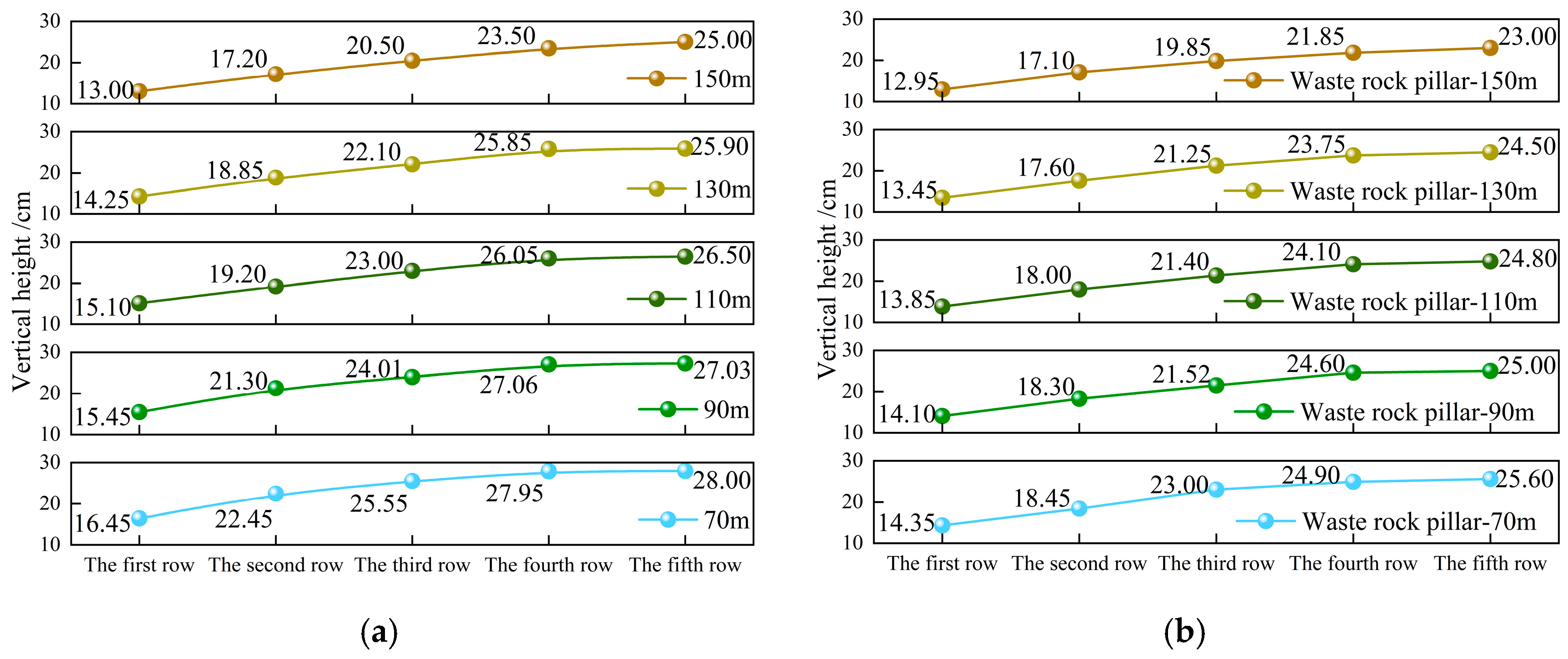
To investigate the influence mechanism of waste rock pillars on the seepage characteristics of tailings dams, a test model without waste rock pillars was constructed. During the dam accumulation process, the drainage system of the waste rock pillars was kept in a closed-valve state until the designed dam crest elevation was reached. After the model was left undisturbed for 24 h, once the water heads at each monitoring point along the seepage line had stabilized, the system collected water level data from the dam seepage line monitoring network (see Figure 4 for experimental data). The vertical height was measured relative to the initial dam base elevation as the reference datum. The dry beach length is defined as the horizontal projection distance between the water boundary of the tailings reservoir area and the contour line of the beach crest. In this study, different operating conditions corresponding to various dry beach lengths were simulated by injecting water at the tail end of the tailings reservoir. It precisely models five typical dry beach lengths: 70 m, 90 m, 110 m, 130 m, and 150 m. Based on geometric similarity principles (scale 1:200), the corresponding model parameters were converted to 0.35 m, 0.45 m, 0.55 m, 0.65 m, and 0.75 m.
Experimental data indicate that when the length of the dry beach was reduced from 150 m to 70 m, the measured rise in the seepage line within the model ranged from 3.00 to 5.25 cm. Based on a 1:200 geometric similarity conversion, the corresponding seepage line burial depth in the prototype project decreased by 6.00 to 10.50 m. Comparative analysis of seepage line changes under different dry beach lengths revealed that longer dry beaches result in deeper seepage line burial. When the waste rock pillar drainage system valves are closed, internal dam drainage is obstructed, leading to a shallower seepage line burial depth.

2.3.2. Seepage Analysis of Tailings Dams Containing Waste Rock Pillars

Different dry beach lengths were simulated at the tail of the tailings reservoir through water injection tests. Analysis of the experimental data indicates that the waste rock pillar drainage system can significantly lower the phreatic line within the reservoir area, allowing infiltrated rainfall on the dry beach to be discharged more rapidly. When the dry beach length was reduced from 150 m to 70 m, the measured rise in the phreatic line in the model ranged from 1.35 to 3.15 cm. In the prototype dam, this corresponds to a reduction in phreatic line depth of 2.70–6.30 m, effectively enhancing the stability of the tailing dam. Through comparative analysis, the introduction of waste rock pillars significantly enhances the drainage efficiency of tailings dams, effectively lowering the seepage line elevation and improving the dam’s seepage stability. Further optimization of waste rock pillar layout and drainage pathways reduces landslide risks caused by excessively high seepage lines, providing robust safeguards for mining safety. These seepage line test results provide critical evidence for the stability assessment in Section 3.

3. Stability Analysis of Tailings Dams Under the Influence of Waste Rock Pillars

3.1. Theory of Stability Calculation

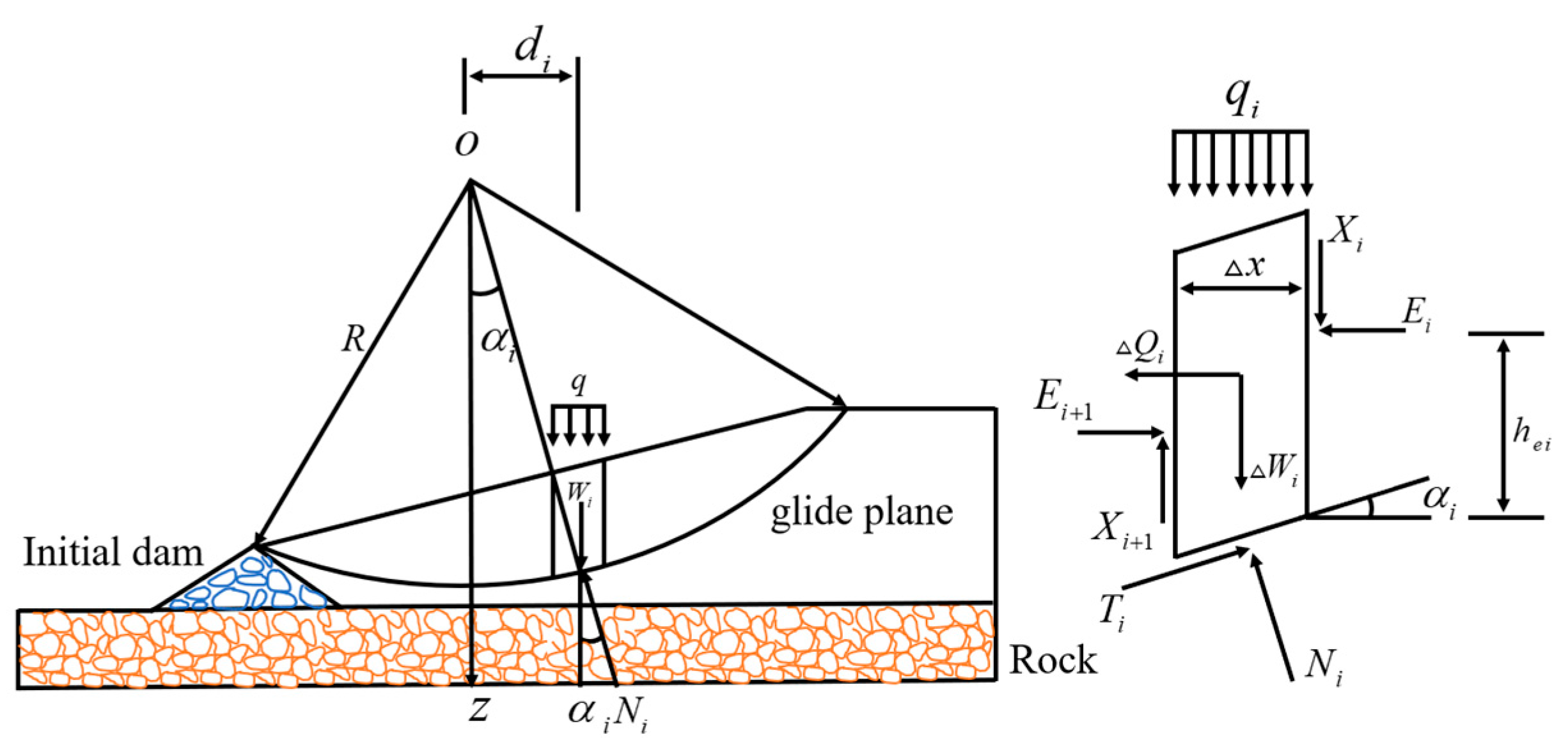
The stability of tailings dams is generally assessed using the limit equilibrium method, with common analytical approaches [26] including the Swedish circle method and the simplified Bishop method [27,28]. In this study, the simplified Bishop method was employed for stability calculations, and the calculation schematic is shown in Figure 5. For a planar sliding surface, the factor of safety can be expressed as:
F s = c l + N tan φ T
In the formula, F s represents the safety factor of the sliding surface; c and φ denote the shear strength parameters of the soil; N and T represent the normal and tangential forces on the sliding surface; l denotes the length of the base edge of the soil strip; R represents the radius of the sliding surface; and h i indicates the location of the point of action. The following assumptions are made:
c e = c F s , tan φ e = tan φ F s
Simplifying the Bishop method by considering the normal forces E i between soil strips, neglecting the tangential forces X i and balancing the vertical forces yields:
W + q i x = N i cos α i + T i sin α i
Conditions for Limit Equilibrium
T i = c e i x sec α i + N i tan φ e i
By combining the two equations, we can solve for
T i = ( W i + q i x ) tan φ e i c e i x cos α i + sin α i tan φ e i
In the formula, x represents the width of the soil strip. For each soil strip as a whole, the moment about the center of the circle in Figure 5 can be calculated as follows:
i = 1 n T i = i = 1 n ( W i + q i x ) sin α i + i = 1 n Q i ( cos α i h e i R )
Since the forces between strips occur in pairs as action and reaction forces, they are equal in magnitude and opposite in direction. When summed, they cancel each other out. Combining the above equations yields:
F s = i = 1 n 1 m α i [ ( W i + q i x ) tan φ i + c i x ] i = 1 n ( W i + q i x ) sin α i i = 1 n ( cos α i h e i R )
In the formula: m α i = cos α i + sin α i tan φ i / F s α i is the base slope angle; is the self-weight of the -th bloc; is the cohesion of the -th soil block; is the internal friction angle; q i is the uniformly distributed vertical overload acting on the soil block slope; Q i is the total horizontal force acting on the soil block.

3.2. Model Establishment

The physical model experiment was used to conceptualize the numerical model (as shown in Figure 6), with two additional waste rock pillars planned to simulate changes in the phreatic line and factor of safety. The parameters listed in Table 2 were determined through a combination of laboratory testing and calibration with engineering survey reports. Particle size distribution, natural unit weight, shear strength, and permeability coefficient were all measured according to the Standard Test Methods for Geotechnical Engineering (GB/T 50123-2019) [29]. The parameters listed in Table 2 were used as input values for the Geo-Studio numerical simulation. This data ensured consistency between the experimental and computational models, thereby enhancing the reliability of the seepage and stability analyses.
The total storage capacity of the tailings dam is 8.36 million m3. According to the Design Specifications for Tailings Facilities (GB 50863-2013) [30], the tailings dam is classified as a Class III facility. For a Class III tailings facility under flood conditions, the factor of safety calculated using the simplified Bishop method is 1.20 (the minimum safety factor is listed in Table 3). Based on a dam height of 1840 m, this study investigates the effects of varying dry beach lengths on the seepage stability of waste rock pillars to reveal the evolution of tailings dam stability under critical conditions.

3.3. Simulation Analysis of Stability for Tailings Dams with Waste Rock Pillars at Different Dry Beach Lengths

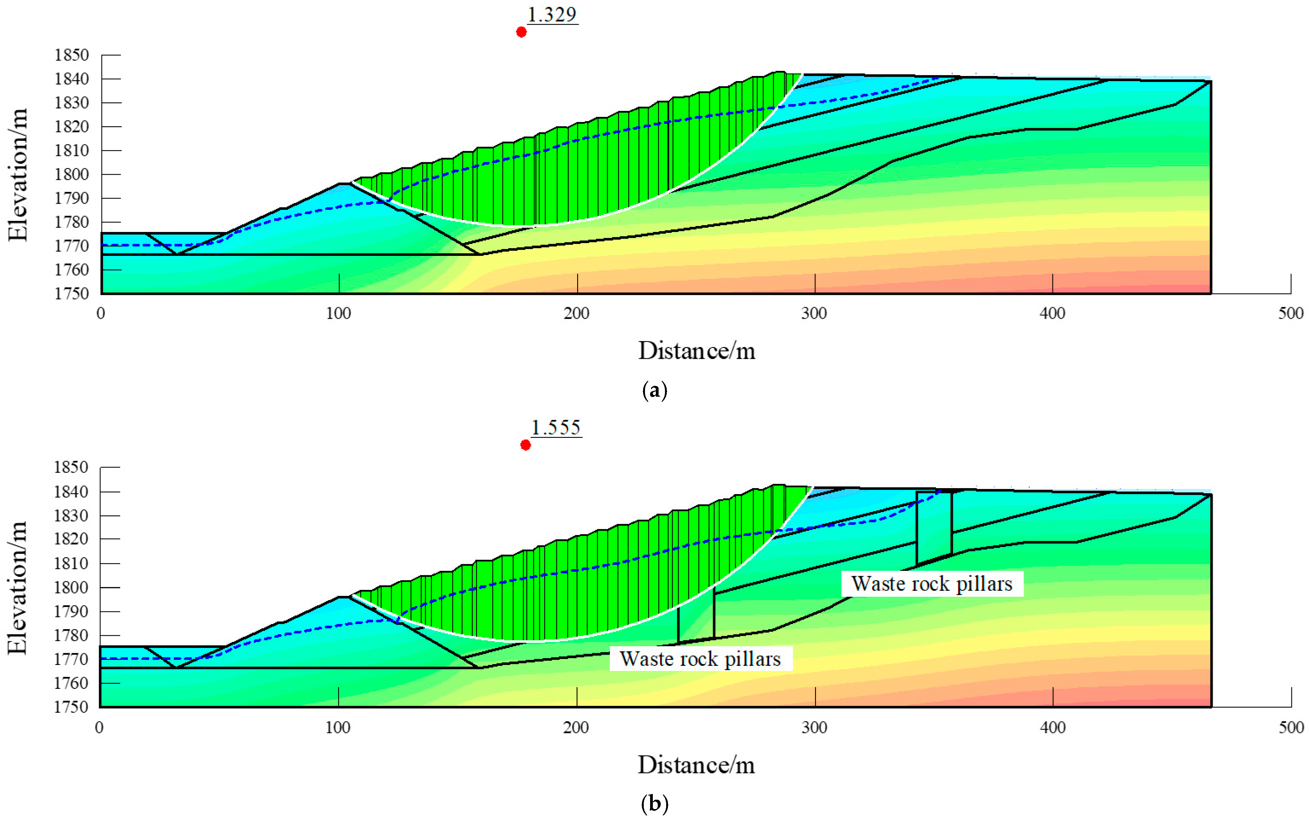
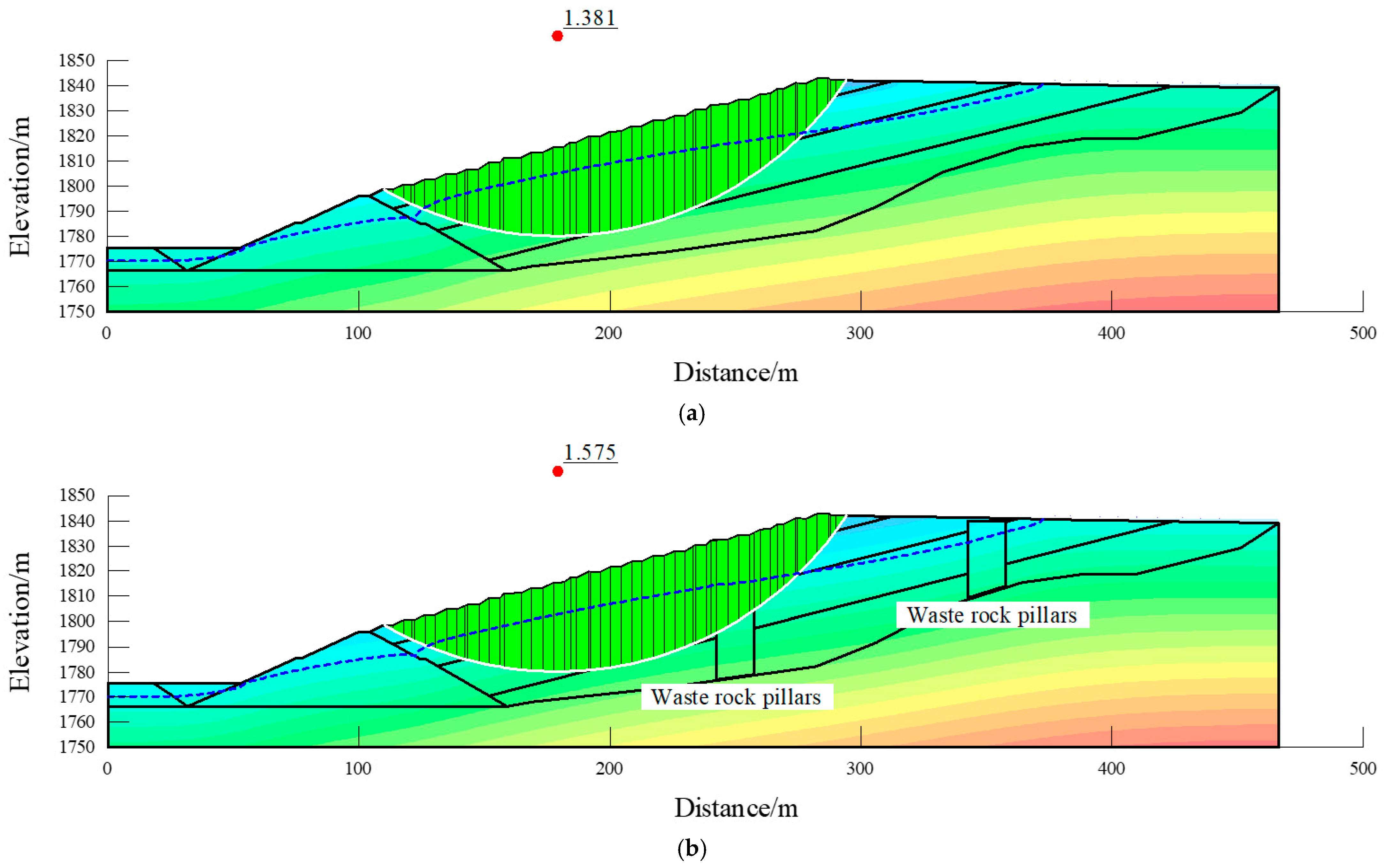
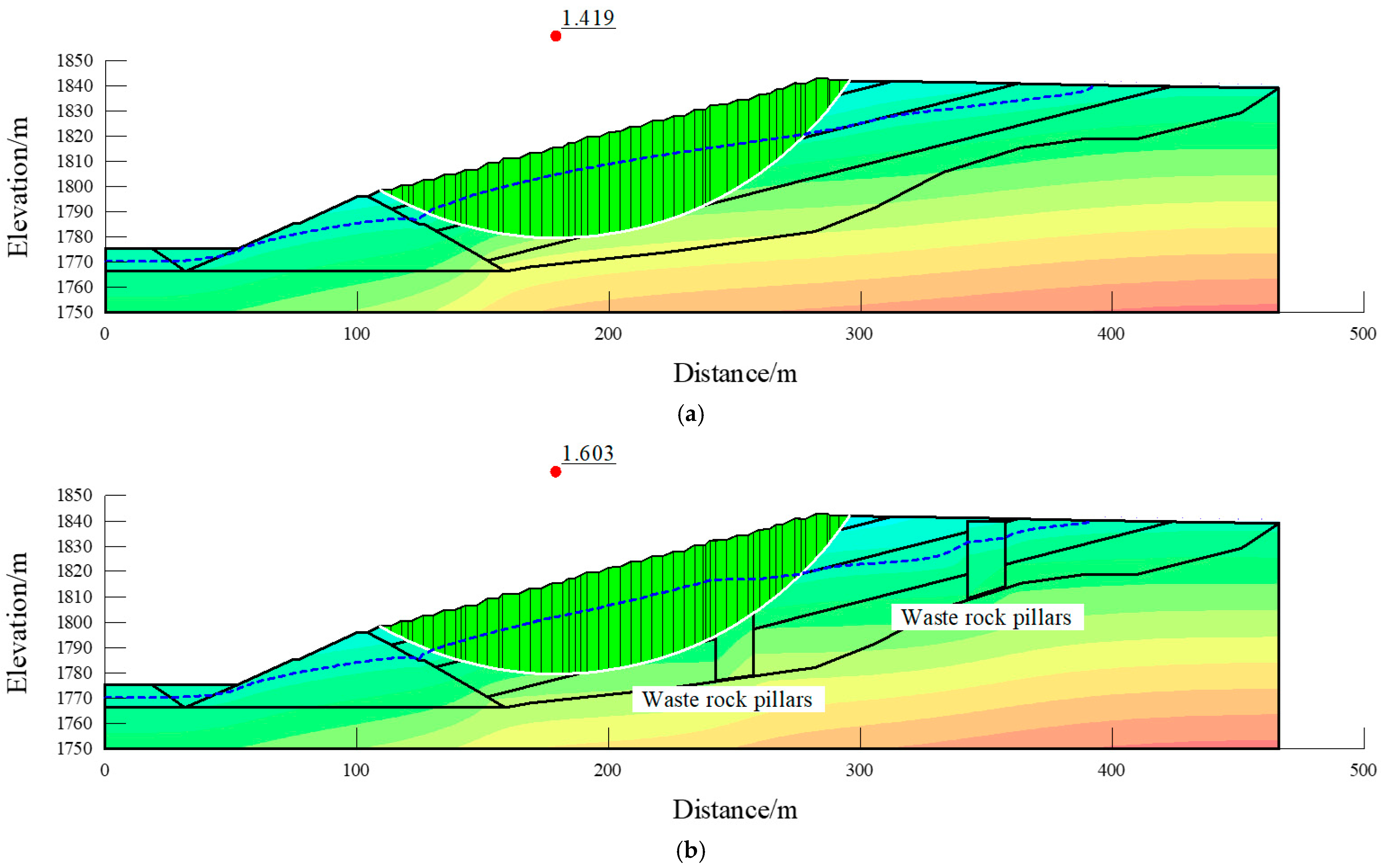
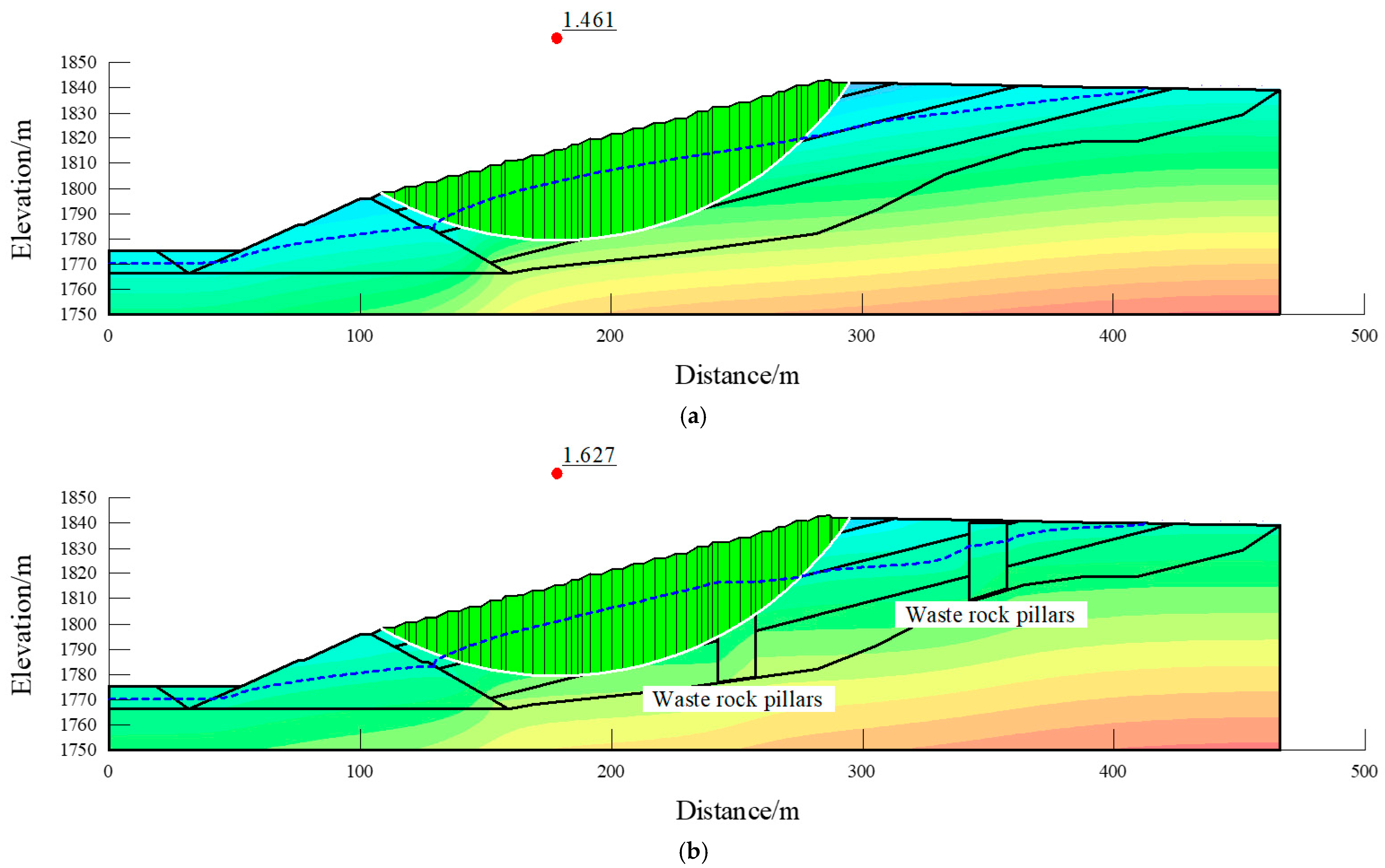
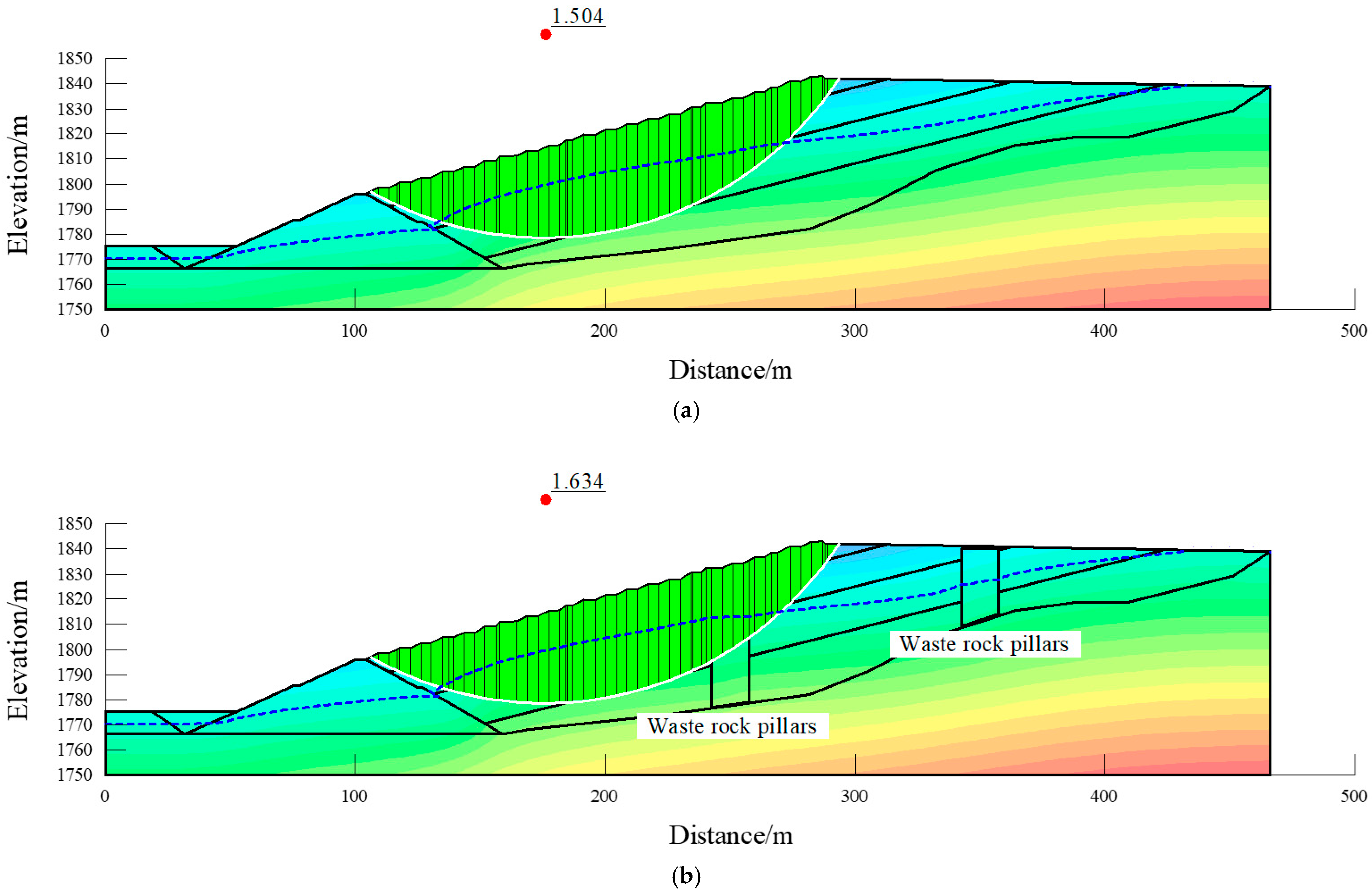
Based on the Geo-Studio geotechnical engineering analysis platform (SEEP/W and SLOPE/W) [31], the SEEP/W module was used to simulate the seepage field, while the SLOPE/W module was employed for limit equilibrium analysis to evaluate the influence of phreatic line depth on tailings dam stability under different dry beach lengths. Stability analyses under different dry beach lengths for the waste rock pillar–tailings co-deposition method at a dam height of 1840 m were conducted using the simplified Bishop method (see Figure 7, Figure 8, Figure 9, Figure 10 and Figure 11).
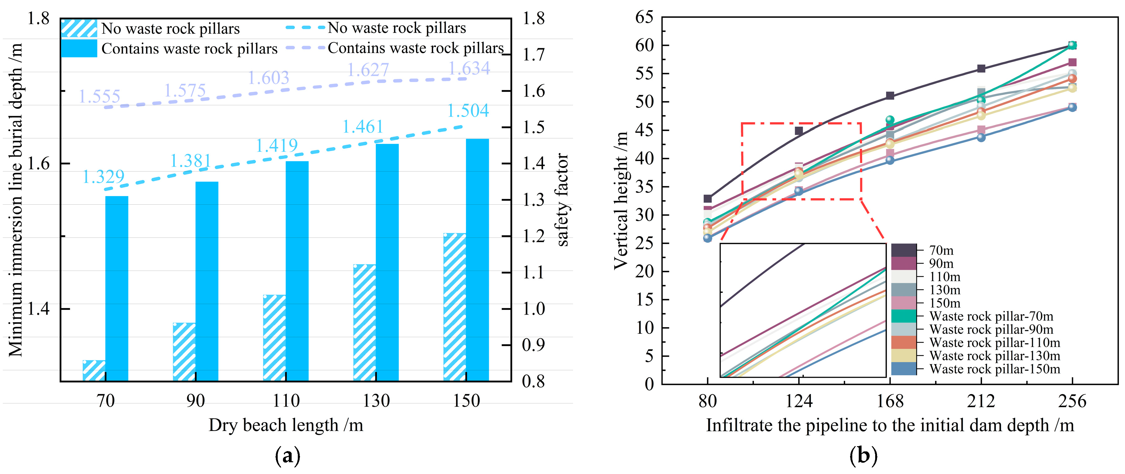
The sliding surface analysis results show that under different dry beach lengths (70 m, 90 m, 110 m, 130 m, and 150 m), the stability safety factors without waste rock pillars are 1.329, 1.381, 1.419, 1.461, and 1.504, respectively. The stability safety factors with waste rock pillars under different dry beach lengths (70 m, 90 m, 110 m, 130 m, and 150 m) are 1.555, 1.575, 1.603, 1.627, and 1.634, respectively (see Figure 12 for the relationship between safety factor and dry beach length). In the absence of waste rock pillars, the safety factors corresponding to different dry beach lengths were obtained by varying the upstream dry beach length of the tailings dam. The results indicate that the safety factor of the tailings dam decreases with the reduction in the dry beach length. After incorporating waste rock pillars into the numerical simulation model, the safety factor increased significantly, with an improvement ranging from 20.0% to 8.6%.
Under all five dry beach length conditions, the calculated safety factors satisfy the minimum slope stability safety factor requirements specified in the Code for Design of Tailings Facilities (GB 50863-2013) [30]. Numerical simulations indicate that the shortening of the dry beach leads to a decrease in the safety factor of the tailings dam and an expansion of the potential sliding surface. Under the condition of a 70 m dry beach, the dam without waste rock pillars exhibits a higher internal water level and a shallower phreatic line. The results reveal that installing a waste rock pillar drainage system at the tail of the tailings pond lowers the phreatic line to a deeper position, thereby enhancing the overall stability of the dam. In terms of seepage stability, the safety factors of dams containing waste rock pillars are significantly higher than those of dams without them.
The simplified Bishop method was adopted due to its computational efficiency and reliable accuracy in assessing the stability of smooth surfaces. Boundary conditions for the numerical model were simplified to ensure numerical stability, assuming the slip surface as a continuous arc and the soil strip as a rigid body. While these assumptions may introduce some uncertainty, physical model tests validated the results, demonstrating good consistency. The proposed waste rock pillar-tailings co-deposition technology demonstrates good applicability in tailings storage facility design, enhancing drainage and stability of existing structures.

3.4. Simulation Analysis of Seepage Stability

Under different dry beach lengths, the seepage field and phreatic line exhibit consistent variation patterns (as shown in Figure 4 and Figure 12). When the dry beach shortens, the upstream infiltration zone shifts closer to the dam body; conversely, when the dry beach extends, the infiltration path becomes longer, and the phreatic line tends to move downward. This trend is identifiable in both the piezometer readings of the physical model and the equipotential line distribution of the numerical simulation results.
The waste rock material itself possesses high shear strength, and its presence directly contributes to improving the slope stability safety factor of the tailings dam. By comparing the tailings dam conditions with and without waste rock pillars, the results indicate that the installation of waste rock pillars can effectively reduce the phreatic line height within the dam body. The effect of lowering the phreatic line is particularly pronounced under the 70 m condition. According to Darcy’s law, the waste rock pillars increase both the equivalent seepage cross-sectional area and the equivalent permeability coefficient, thereby enhancing the discharge capacity under a given hydraulic head. This explains why their water-conducting performance surpasses that of traditional drainage pipes. In addition, the waste rock pillars can be structurally analogous to pile foundations with inherent shear strength, which effectively enhances the shear resistance of the downstream dam body and thereby improves the overall anti-sliding stability of the tailings dam. Based on the experimental data and stability analysis, when the dry beach is short, the drainage elements primarily function as “localized drainage collectors.” In contrast, with longer dry beaches, the effects of “flow channel extension and equipotential line reshaping” become more pronounced. Moreover, optimizing the arrangement and number of waste rock pillars can further enhance their positive contribution to dam stability.
The rational arrangement of waste rock pillars provides a new drainage pathway, effectively discharging water from the tailing pond through the pillars. This reduces the rise in the phreatic line, significantly decreases internal seepage pressure within the dam body, and further enhances the overall stability and safety of the tailings dam. Moreover, the perforation area, arrangement, and quantity of waste rock pillars are key factors influencing their drainage performance. Through scientific design, the drainage efficiency can be maximized, ensuring the stable operation of the tailings reservoir under varying water level conditions and effectively reducing the risk of dam failure.

4. Discussion

This study establishes an evidence chain of “physical modeling–GeoStudio seepage/slope stability coupling,” confirming that under varying dry beach lengths, the waste rock pillar–tailings co-deposition approach effectively lowers the phreatic line within the dam and enhances the stability safety factor (e.g., increasing from 1.329 to 1.555 at a 70 m dry beach, and from 1.504 to 1.634 at a 150 m dry beach). These results are consistent with previous findings and further quantify the magnitude of improvement. Compared with traditional PVC + geotextile drainage pipes, which are limited by perforation area and clogging issues, the structure proposed in this study adopts an “outer stainless-steel mesh + filter geotextile + internally graded waste rock” configuration. This design forms a highly permeable interface and an anti-clogging skeleton, mechanically functioning as a composite seepage-control system that integrates a “three-dimensional drainage channel” and a “pile-effect reinforcement.” Compared to recent technologies such as composite drainage pipes, dam crest horizontal drainage, and drainage walls/shafts, the waste rock pillars approach offers marginal advantages in resource utilization of mine waste rock, expansion of effective inflow area, and provision of shear strength. In contrast to geogrid reinforcement methods that lower the phreatic line, the waste rock pillar more directly reconstructs the seepage path, yielding a more pronounced drainage effect.
The main innovations of this study are reflected in: Integrated component design: This work proposes an integrated “high-permeability–anti-clogging–load-bearing” waste rock pillar structure, which organically combines seepage regulation, clogging resistance, and load-bearing capacity to form a composite seepage-control system. Mutual verification framework of indoor physical modeling and 2D numerical simulation: This approach bridges the limitations of relying solely on experiments or simulations, strengthening the linkage between theoretical analysis and engineering application. It clarifies the variation pattern of stability improvement with changing dry beach lengths. Engineering sustainability and circular economy: The study emphasizes the resourceful use of mine waste rock and the reduction in material consumption, embedding sustainability and economic efficiency into the design concept.
Limitations: Stability was assessed solely using the simplified Bishop method, without cross-verification with methods such as the Swedish slice method. Coupled multi-hazard conditions, including seismic events, extreme rainfall, and chemically induced clogging, still require long-term field monitoring and 3D optimized layouts for validation. It is recommended to conduct comparative trials in the tailings pond prototype: optimize pillar spacing and open area ratio by zone, integrate with the online monitoring platform, and evaluate the relationship between seepage discharge efficiency, safety factor, and maintenance costs throughout the tailings pond’s service life.
Physical model tests and numerical simulation results indicate that installing waste rock pillars within the tailings pile effectively lowers the seepage line, reduces pore water pressure, and enhances the overall stability of the dam structure. Under varying dry-bed lengths, the dam’s safety factor increased by 8.6–20.0%. This improvement stems from the preferential drainage pathways formed by waste rock pillars and the structural reinforcement effect provided by coarse-grained materials. The proposed composite design combines drainage and reinforcement functions while enabling the reuse of on-site waste rock resources, offering a sustainable alternative to traditional drainage systems prone to clogging and deterioration. This method can be applied to both newly constructed and existing tailings dams, particularly in projects requiring enhanced seepage control and stability improvement. However, its continuous drainage performance under field conditions, clogging evolution, and economic viability still require long-term monitoring and validation. The simplified Bishop method employed for stability analysis is applicable to the analysis of circular arc slip surfaces in homogeneous dams, but it has certain limitations when dealing with highly anisotropic or non-circular arc failure scenarios. Overall, this study provides a technically viable approach with practical value for enhancing the safety and sustainability of tailings dams.

5. Conclusions

This study investigated the drainage performance and stability enhancement of tailings dams using a combined waste rock pillar–tailings filling method through physical model tests and numerical simulations. The key findings can be summarized as follows:
(1)
For tailings dams without waste rock pillars, reducing the dry beach length from 150 m to 70 m caused the phreatic line to rise by 3.00–5.25 cm in the physical model. In contrast, dams incorporating waste rock pillars showed a smaller rise of only 1.35–3.15 cm under the same conditions. These results demonstrate that the proposed structure effectively deepens the burial depth of the phreatic line
(2)
The safety factor decreases as the dry beach shortens; however, incorporating waste rock pillars significantly enhances dam stability. Numerical results show that the safety factor increased from 1.329 to 1.555 at a 70 m dry beach length and from 1.504 to 1.634 at 150 m, representing improvements of 20.0% and 8.6%, respectively.
(3)
The waste rock pillars provide a substantially larger seepage area and greater resistance to clogging than traditional drainage pipes, resulting in enhanced drainage efficiency, reduced pore-water pressure, and improved downstream shear strength.
The research findings indicate that the proposed combined waste rock pillar–tailings co-stacking scheme achieved the predetermined research objectives and can serve as an effective approach to enhance drainage and stability in tailings dams. This method offers a novel technical approach for achieving safer and more sustainable tailings dam designs by lowering the elevation of the seepage line and mitigating stability issues caused by seepage. This study still has limitations: the scale and boundary conditions of the physical model tests cannot fully reflect the complexity of the actual site. The numerical simulation employed a simplified Bishop method based on several idealized assumptions. The coupled stress–seepage behavior of waste rock pillars under long-term seepage and loading has not yet been systematically evaluated. Future work should include long-term field monitoring, full-scale pilot applications, and refined numerical modeling to evaluate clogging evolution, structural durability, and economic feasibility, thereby supporting broader engineering adoption.

Author Contributions

Conceptualization, S.W., B.Z., R.L. and B.Z.; methodology, S.W. and B.Z.; software, S.W. and B.Z.; validation, R.L.; formal analysis, S.W. and B.Z.; investigation, S.W. and R.L.; data curation, S.W.; writing—original draft preparation, S.W. and B.Z.; writing—review and editing, S.W.; supervision, B.Z. and M.L. All authors have read and agreed to the published version of the manuscript.

Funding

Key Project of Yunnan Provincial Basic Research Program (202401AS070071), Youth Project of Yunnan Provincial Basic Research Program (202501AU070145), Yunnan Province Phosphorus Resources Technology Innovation Center, Research on Intelligent Mining and Green Sorting Technology (202305AK340002-1), Central Guidance Fund for Local Science and Technology Development (202407AC110019-1).

Institutional Review Board Statement

Not applicable.

Informed Consent Statement

Not applicable.

Data Availability Statement

The data presented in this study are available on request from the corresponding author. The data are not publicly available due to privacy restrictions.

Conflicts of Interest

Authors Rong Lan and Mingsheng Liu were employed by the company Kunming Nonferrous Metals Design & Research Institute Co., Ltd. The remaining authors declare that the research was conducted in the absence of any commercial or financial relationships that could be construed as a potential conflict of interest.

References

  1. Zare, M.; Nasategay, F.; Gomez, J.A.; Moayedi Far, A.; Sattarvand, J. A Review of Tailings Dam Safety Monitoring Guidelines and Systems. Minerals 2024, 14, 551. [Google Scholar] [CrossRef]
  2. Al-Janabi, A.M.S.; Dibs, H.; Sammen, S.S.; Yusuf, B.; Ikram, R.M.A.; Alzuhairy, S.H.; Kisi, O. Comparison Analysis of Seepage Through Homogenous Embankment Dams Using Physical, Mathematical and Numerical Models. Arab. J. Sci. Eng. 2025, 50, 8143–8152. [Google Scholar] [CrossRef]
  3. Contreras, C.A.; Yniesta, S.; Aubertin, M. Improvement of Tailings Impoundment Seismic and Post-Seismic Stability Using Densification and Waste Rock Inclusions. Can. Geotech. J. 2023, 60, 1629–1644. [Google Scholar] [CrossRef]
  4. Zeng, K.; Dai, H.; Yao, H. Fine Tailings Heap High Levels of Radiation Seepage Drainage Wells Application. IOP Conf. Ser. Earth Environ. Sci. 2019, 283, 012022. [Google Scholar]
  5. Zhang, H.; Shen, Z.; Liu, D.; Xu, L.; Gan, L.; Long, Y. A Suggested Equivalent Method for a Drainage Structure to Analyze Seepage in Tailings Dam. Materials 2022, 15, 7154. [Google Scholar] [CrossRef]
  6. Du, S.; Liu, P.; Wang, W.; Shi, W.; Li, Q.; Li, J.; Li, J. Numerical Simulation and Analysis of the Influencing Factors of Foundation Pit Dewatering under a Coupled Radial Well and Curtain. Water 2023, 15, 1839. [Google Scholar] [CrossRef]
  7. Jin, S.L.; Xu, H.D.; Zhang, W.; Yan, H.; Wu, Z.X. Research on Calculation Method and Drainage Mechanism of Slotted Pipe in Fine-Grained Tailings Dam. Metal Mine 2013, 03, 42–44+48. [Google Scholar]
  8. Zhang, S.M.; Cui, X. Analysis of the influence of three-dimensional drainage facilities in the soft beach on the seepage field of tailings pond. China Min. 2024, 33 (Suppl. 1), 157–163. [Google Scholar]
  9. Yang, H.; Wu, J.; Guo, C.; Li, H.; Wu, Z. Effects of Geotextile Envelope and Perforations on the Performance of Corrugated Drain Pipes. Int. J. Agric. Biol. Eng. 2023, 16, 36–44. [Google Scholar] [CrossRef]
  10. Xie, S.; Liu, H.; Huang, H.; Ye, F. Experimental Study on Effect of Geotextile Filter Layer on Flow of Perforated Pipe. J. Drain. Irrig. Mach. Eng. 2022, 40, 576–581. [Google Scholar]
  11. Yang, C.H.; Li, Z.H.; Mao, H.J.; Yang, J.; Zhang, C. Experimental study on the clogging mechanism of drainage system in tailings dam. J. Guangxi Univ. (Nat. Sci. Ed.) 2019, 44, 845–854. [Google Scholar]
  12. Wu, H.M.; Wang, W.S.; Yang, L.; Zhang, Z.; Ou, Z. Research on the Permeability Characteristics of Iron Tailings-Geotextile Filter Under Vacuum Conditions. J. Hohai Univ. (Nat. Sci. Ed.) 2025, 1–10. [Google Scholar]
  13. Du, C.; Tao, H.; Yi, F. Seepage Stability Analysis of Geogrid Reinforced Tailings Dam. Sci. Rep. 2024, 14, 1814. [Google Scholar] [CrossRef] [PubMed]
  14. Liu, C.; Shen, Z.; Gan, L.; Xu, L.; Zhang, K.; Jin, T. The Seepage and Stability Performance Assessment of a New Drainage System to Increase the Height of a Tailings Dam. Appl. Sci. 2018, 8, 1840. [Google Scholar] [CrossRef]
  15. Liu, S.; Wang, Y.; Feng, D. Experimental study on drainage characteristics of new composite drainage pipes in tailings pond. Chin. J. Geotech. Eng. 2019, 41, 2360–2366. [Google Scholar]
  16. Wang, C.; Li, L.; Wen, J.H.; Cai, F.Z.; Xu, L. Influence of single-row horizontal drainage pipe layout at top of initial dam on stability of tailings dam. China Saf. Prod. Sci. Technol. 2024, 20, 125–131. [Google Scholar]
  17. Chen, J.H.; Liu, X.W. Influence of different drainage pipe arrangement schemes on the seepage line of seepage field in tailings reservoir. Light Metal. 2020, 2, 1–8. [Google Scholar]
  18. Deni, M.C.N.; Afandi, K.; Sinamo, B.; Satriawan, A. Co-Disposal as an Alternative Method for Waste Rock and Tailings Management—A Review of Geochemical Aspects. IOP Conf. Ser. Earth Environ. Sci. 2024, 1422, 012003. [Google Scholar] [CrossRef]
  19. Saleh-Mbemba, F.; Aubertin, M. Physical and Numerical Modelling of Drainage and Consolidation of Tailings near a Vertical Waste Rock Inclusion. Can. Geotech. J. 2021, 58, 1263–1276. [Google Scholar] [CrossRef]
  20. Nguyen, N.D.; Pabst, T. Acceleration of Consolidation of Tailings in a Pit Using Waste Rocks Co-Disposal. Geotech. Geol. Eng. 2024, 42, 1593–1609. [Google Scholar] [CrossRef]
  21. Burden, R.; Wilson, G.W. Commingling of Waste Rock and Tailings to Improve “Dry Stack” Performance: Design and Evaluation of Mixtures. Minerals 2023, 13, 295. [Google Scholar] [CrossRef]
  22. Han, Y.; Wang, G.; Zhang, X.; Zhao, B. Numerical Simulation of Seepage Surface and Analysis of Phreatic Line Control from a Fine-Grained Tailings High Stacked Dam under Complicated Geography Conditions. Appl. Sci. 2023, 13, 12859. [Google Scholar] [CrossRef]
  23. Yang, J.; Hu, J.; Wu, Y.; Zhang, B. Numerical Simulation of Seepage and Stability of Tailing Dams: A Case Study in Ledong, China. Sustainability 2022, 14, 12393. [Google Scholar] [CrossRef]
  24. Zhao, B.; Wang, G.J.; Liu, W.L.; Wu, S.; Xu, H. Numerical Simulation and Experimental Analysis of Three-dimensional Seepage Field of Tailings Dam Body. Nonferrous Met. Eng. 2020, 10, 99–106. [Google Scholar]
  25. Rocha, A.H.; Becker, L.D.B. Development of an Apparatus for Physical Modeling of Tailings Dams: Preliminary Tests. In Proceedings of the 5th European Conference on Physical Modelling in Geotechnics, Delft, The Netherlands, 2–4 October 2024. [Google Scholar]
  26. Bella, G.; Freire, C.; Lameiras, F.; Giani, M. Numerical Investigation on Tailing Dams Stability: A Preliminary, Parametric Analysis of Some Key Factors. In Proceedings of the 8th World Congress on Civil, Structural, and Environmental Engineering (CSEE’23), Lisbon, Portugal, 29–31 March 2023. [Google Scholar]
  27. Wang, K.; Zhang, Z.; Yang, X.; Wang, D.; Zhu, L.; Yuan, S. Enhanced Tailings Dam Beach Line Indicator Observation and Stability Numerical Analysis: An Approach Integrating UAV Photogrammetry and CNNs. Remote Sens. 2024, 16, 3264. [Google Scholar] [CrossRef]
  28. Li, Q.; Ma, G.; Lu, Y. An Experimental and Theoretical Study on the Tailings Dam with Geotextile Bags. Sustainability 2023, 15, 4768. [Google Scholar] [CrossRef]
  29. GB/T 50123-2019; Standard Test Methods for Geotechnical Engineering. Ministry of Housing and Urban-Rural Development of the People’s Republic of China: Beijing, China, 2019.
  30. GB 50863-2013; Design Specifications for Tailings Facilities. Ministry of Housing and Urban-Rural Development of the People’s Republic of China: Beijing, China, 2013.
  31. Khanal, M.; Shi, J.; Qu, Q. Effect of Stepwise Increase in Tailings Deposition on Tailings Dam Stability. Minerals 2025, 15, 346. [Google Scholar] [CrossRef]
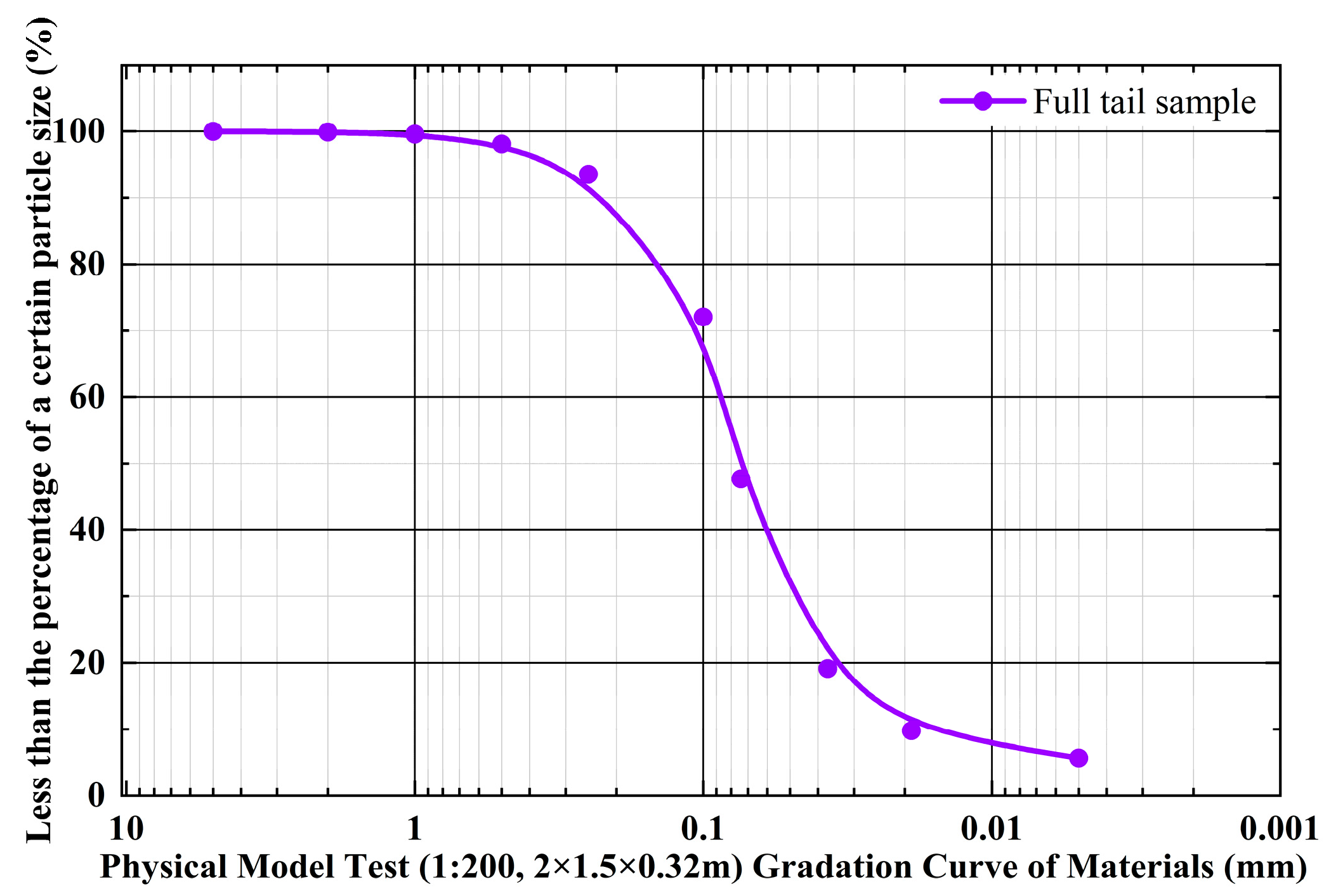
Figure 1. Particle size cumulative distribution curve.
Applsci 15 12348 g001
Figure 2. Physical model of combined stockpiling of waste rock pillars and tailings.
Applsci 15 12348 g002
Figure 3. Physical experiment model construction.
Applsci 15 12348 g003
Figure 4. Data on water level changes in individual monitoring tubes: (a) No waste rock pillars; (b) waste stone pillars.
Applsci 15 12348 g004
Figure 5. Bishop’s Block Force Analysis.
Applsci 15 12348 g005
Figure 6. Tailings dam calculation profile diagram.
Applsci 15 12348 g006
Figure 7. Calculation of the seepage stability of the dam body (dry beach length 70 m). (a) No waste rock pillars; (b) Containing waste rock pillars. The red dots represent the centers of slip surfaces. The green regions denote slip surfaces. The dashed blue lines indicate the wetting line, while the solid black lines show the layering conditions for each region (see Figure 6).
Applsci 15 12348 g007
Figure 8. Calculation of the seepage stability of the dam body (dry beach length 90 m). (a) No waste rock pillars; (b) Containing waste rock pillars. The red dots represent the centers of slip surfaces. The green regions denote slip surfaces. The dashed blue lines indicate the wetting line, while the solid black lines show the layering conditions for each region (see Figure 6).
Applsci 15 12348 g008
Figure 9. Calculation of the seepage stability of the dam body (dry beach length 110 m). (a) No waste rock pillars; (b) Containing waste rock pillars. The red dots represent the centers of slip surfaces. The green regions denote slip surfaces. The dashed blue lines indicate the wetting line, while the solid black lines show the layering conditions for each region (see Figure 6).
Applsci 15 12348 g009
Figure 10. Calculation of the seepage stability of the dam body (dry beach length 130 m). (a) No waste rock pillars; (b) Containing waste rock pillars. The red dots represent the centers of slip surfaces. The green regions denote slip surfaces. The dashed blue lines indicate the wetting line, while the solid black lines show the layering conditions for each region (see Figure 6).
Applsci 15 12348 g010
Figure 11. Calculation of the seepage stability of the dam body (dry beach length 150 m). (a) No waste rock pillars; (b) Containing waste rock pillars. The red dots represent the centers of slip surfaces. The green regions denote slip surfaces. The dashed blue lines indicate the wetting line, while the solid black lines show the layering conditions for each region (see Figure 6).
Applsci 15 12348 g011
Figure 12. Infiltration line vs. safety factor relationship diagram (a) Safety factor vs. dry beach length relationship diagram (b) Numerical simulation of infiltration line trend diagram.
Applsci 15 12348 g012
Table 1. Model test similarity parameters.
Physical Quantity/UnitSimilarity ScaleModel Test Parameters
Length/m1:2002.00
Width/m1:2001.50
Height/m1:2000.32
Flow velocity/(cm/s)1:13.969.60
Gravity acceleration/(m/s2)1:19.80
Table 2. Tailings physico-mechanical parameter index values.
NameNatural Weight (kN/m3)Cohesion (kPa)Internal Friction Angle (°)Permeability Coefficient (cm/s)
Round gravel22.01.035.03.0 × 10−3
Plain fill soil19.05.012.03.0 × 10−3
Initial dam24.05.435.05.0 × 10−3
Tail sand19.92.425.21.4 × 10−3
Tail fine sand20.24.123.41.0 × 10−4
Tail powder sand20.45.421.68.6 × 10−4
Tail Silty clay18.923.515.51.2 × 10−6
Rock23.05.040.03.0 × 10−7
Waste Rock Pillars20.043.536.09.5 × 10−2
Table 3. Minimum Safety Factor for Slope Stability Against Landslides.
Calculation MethodOperating ConditionsDam Classification
1234, 5
Simplified Bishop’s LawNormal operation1.501.351.301.25
Flood Run1.301.251.201.15
Disclaimer/Publisher’s Note: The statements, opinions and data contained in all publications are solely those of the individual author(s) and contributor(s) and not of MDPI and/or the editor(s). MDPI and/or the editor(s) disclaim responsibility for any injury to people or property resulting from any ideas, methods, instructions or products referred to in the content.