Article

Overburden Behavior and Coal Wall Spalling Characteristics Under Large-Mining-Height Conditions

1
School of Mechanics and Civil Engineering, China University of Mining and Technology, Xuzhou 221116, China
2
State Key Laboratory for Intelligent Construction and Healthy Operation and Maintenance of Deep Underground Engineering, China University of Mining and Technology, Xuzhou 221116, China
*
Author to whom correspondence should be addressed.
Appl. Sci. 2025, 15(22), 12303; https://doi.org/10.3390/app152212303
Submission received: 28 September 2025 / Revised: 18 November 2025 / Accepted: 18 November 2025 / Published: 20 November 2025

Abstract

Large-mining-height technology has been increasingly applied in thick seam mining to enhance productivity and resource recovery. However, it also intensifies strata pressure and complicates surrounding rock control, leading to greater overburden movement, stronger roof weighting, and severe coal wall spalling. Taking the 12306 working face of the Wangjialing Mine as a case, this study employs physical similarity experiments and UDEC numerical simulations to investigate the coupled mechanism of overburden migration and coal wall instability. Results show that abutment stress induces non-uniform deformation, while strata pressure changes directly govern spalling depth. Moreover, coal wall instability is strongly affected by multiple factors: greater burial depth intensifies crack propagation, larger mining height expands failure depth, larger mining step size extends the stress-affected zone, larger dip angle shifts failure upward, and lower support resistance weakens control capacity. These findings clarify the disaster mechanism of deep large-mining-height faces and provide theoretical and engineering guidance for optimizing support design and enhancing coal wall stability.

1. Introduction

With the increasing demand for deep coal extraction, large-mining-height technology has been widely applied in thick seams. While enhancing productivity and recovery, it intensifies strata pressure and complicates surrounding rock control. Compared with conventional faces, large-mining-height panels exhibit stronger overburden movement, broader abutment pressure, more severe roof failure, and higher risks to production safety.
Coal wall spalling is especially critical under such conditions. Greater mining heights increase both the magnitude and duration of roof pressure, causing large-scale and deep failures. These can block shearer cutting ports, enlarge support end distances, and, under fractured roofs or delayed support, trigger roof falls and support instability.
Li et al. [1,2,3] showed that once the primary key stratum destabilizes, overburden and ground movements escalate nonlinearly; reinforcement beneath fracture belts can suppress subsidence and delay first weighting. Analytical envelopes of overburden movement, such as arch- and hyperbola-type bounds, have been proposed to constrain subsidence prediction and safeguard key strata when incorporated into models [4,5,6]. For thick seams, Wu et al. [7,8] described a hybrid roof evolution (cantilever → non-hinged → hinged), explaining alternating small–large periodic weighting and shifting stress peaks. Field evidence at shallow to medium burial depths shows advance-influence ranges of tens of meters and step-like deflection governed by key-strata spacing and integrity [7,8,9]. BOTDA/DOFS and microseismic arrays capture “first/periodic” weighting via strain jumps, enabling online identification of weighting intervals and roof separation [10,11]. Geomorphic setting and alternative layouts, such as protected-strata and cut-slot mining, reshape the classical three-zone structure, attenuating subsidence and limiting fracture propagation [5,12]. Parametric analyses link drawing angle, bulking factor (~1.3–1.5), and key-strata thickness to gob compaction and support demand, providing ranges directly applicable to FLAC3D/UDEC simulations [3,9,13].
Rib spalling at deep or large-height faces arises from tensile–shear coupling in coal–rock composites under non-uniform abutment and dynamic effects. Laboratory and numerical studies show cracks nucleating in coal and propagating into rock, with failure shifting from tensile near the face to mixed/shear farther ahead; dip angle moves stress peaks outward and switches the dominant mode between tension (horizontal/up-dip) and shear (down-dip) [14,15,16,17]. Sensitivity analyses rank cohesion and friction angle as key controls, with support strength and mining height secondary; even a 1 MPa cohesion increase can markedly reduce deformation [18,19]. Field surveys locate a high-frequency spalling band within ~0–1.0 m, concentrated at 0.3–0.6 m, informing reinforcement horizons [19]. Dynamic factors, such as cutter-induced vibrations (~7–12 Hz) and prior strong shocks, promote repeated tensile zones and accelerate brittleness [20]. At ultra-large heights, stability depends on overturning and sliding limits; wider bases and sufficient initial set pressure mitigate burst-type failures [21]. The main weighting period (MWP) remains the most hazardous stage, with severe spalling often after tens of meters of advance and depths up to one meter [22,23].
Within this framework, control is treated as part of the mechanism: advance grooving (pre-slotting) translates and attenuates peak pressures, with optimal groove ratios (height/depth ≈ 0.75) shifting them forward and reducing amplification, especially with slower advance in MWP [24]. Support design has progressed to a two-factor scheme coupling roof-bearing demand with side-wall protection, taking the upper envelope of both as the resistance target [25]. Large-height top-coal faces also benefit from coordinated adjustment of cutting height, roof-break position, support resistance, and side-shield force, which reduces displacement and plastic volume in both simulations and field applications [26].
Although overburden movement and coal rib spalling have been widely studied individually, integrated research—especially on their coupled behavior under large-mining-height conditions—is still limited. Recent studies (e.g., Li et al. [19], Zhang et al. [21], Wang et al. [25]) mostly use field monitoring, single-parameter simulations, or standalone lab tests, and thus do not capture the dynamic interaction between roof instability and rib failure. For example, ref. [19] identified spalling-prone zones, ref. [21] examined support stability under overturning, and [25] proposed a dual-factor support design combining roof support and rib protection—but none directly links real-time overburden evolution with progressive rib damage in a unified, physically consistent framework.
This gap is especially critical at the 12306 longwall face in Wangjialing Mine, where the recent transition from top-coal caving to full-seam mining in a single lift has significantly increased mining height. The resulting intensification of overburden movement has led to extensive strata failure, frequent large-scale and deep-seated rib spalling, and unclear abutment stress distribution and support loading demands—posing serious challenges to safe and efficient extraction.
To address these issues, this study integrates physical similarity modeling with UDEC distinct element simulations to systematically investigate the coupled evolution of overburden failure, abutment pressure, and coal wall instability under large-mining-height conditions. The effects of key parameters—including burial depth, mining height, seam dip angle, mining step size, and hydraulic support resistance—are evaluated. The results elucidate the interaction mechanisms between strata movement and rib spalling, providing both theoretical insights and practical guidance for ground control and optimized mining design in similar geological settings.

2. Engineering Background

Wangjialing Mine is situated in Xiangning County, Shanxi Province, within a major North China coal base, boasting a prime location and transport links. The mining area contains Carboniferous–Permian coal measures, featuring stable seam occurrence and simple geology. The No. 2 and No. 10 seams are the principal minable layers. The No. 2 seam averages 5.9 m in thickness, lies about 300 m deep, has a simple structure, and dips gently (3–5°). It demonstrates good roof and floor stability, straightforward hydrogeology, low water inflow, and is classified as low-gas.
The 12306 working face is located in the southeast of panel 123, adjacent to the planned 12308 face in the north, the 12304 goaf in the south, the No. 2 coal central haulage roadway in the west, and a protective coal pillar beneath the G209 Highway in the east. The surface elevation ranges from +862.2 to +1093.4 m, and the underground elevation from +550 to +635 m. The panel has an advance length of 2913.2 m and a width of 311 m, and adopts full-height extraction of the No. 2 coal seam.
The coal seam in the study area has a burial depth of ~543 m and occurs nearly horizontally. Its Protodyakonov hardness coefficient is f = 0.5–0.7, indicating soft coal. The seam thickness is 5.9 m, with a 6.6 m siltstone immediate roof and a 9.2 m interbedded fine- to medium-grained sandstone main roof. Based on the comprehensive geological column of the mine and the geological column of the 12306 working face, a geological column ranging from 409.2 m to 565 m in depth was constructed, as shown in Figure 1.

3. Study on the Movement Law of Overlying Strata in a Large-Mining-Height Face Based on Physical Similarity Modeling

3.1. Experimental Design of Similarity Model for Overburden Movement in Large-Mining-Height Working Face

3.1.1. Similarity Model Experimental Design

To analyze the dynamic evolution of overburden failure, strata pressure behavior, and the mining-induced stress field in large-mining-height working faces, a similarity model experiment was conducted using a multifunctional mining plane physical simulation system. The model, with dimensions of 2500 mm × 300 mm × 1500 mm, was conducted under plane strain conditions. Similarity ratios were set as follows: geometric 1:100, bulk density 1:1.5, strength 1:150, and elastic modulus 1:150.
The mass ratio of similitude materials (river sand/gypsum powder/calcium carbonate powder) was based on previous research conducted by our research group [27], the monograph Similarity Simulation Experiments of Mine Strata Pressure as well as ref. [28]. This ratio was selected to match the key geomechanical properties (such as density, strength, and modulus) of the in situ overburden strata at the 12306 longwall face (mainly sandstone, siltstone, and mudstone), satisfying the criteria for geometric, density, and strength similarity to ensure an accurate replication of the prototype rock mass behavior. Table 1 presents the physico-mechanical parameters of the rock mass and similitude materials, which meet these similarity criteria.
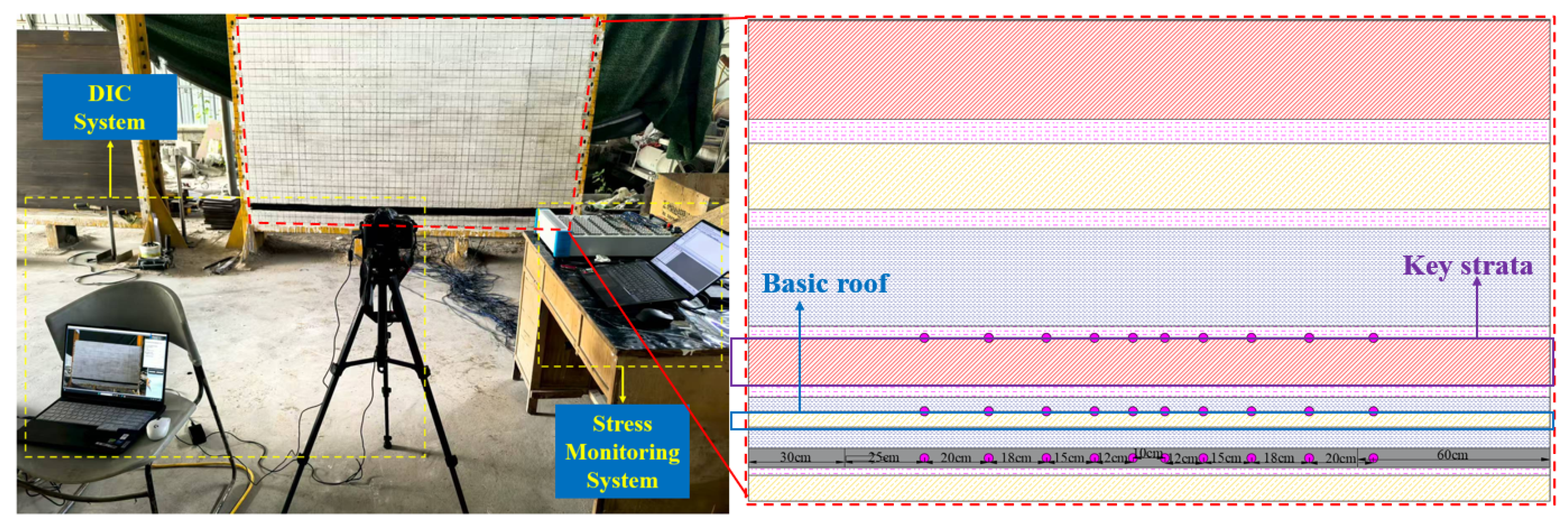
After curing to the required strength, progressive mining was simulated according to the similarity time scale. The surface displacement field was monitored using a Digital Image Correlation (DIC) system. Stress data from both the coal seam and the roof were also collected using a stress monitoring system, providing the basis for analyzing overburden movement and mining-induced stress distribution.

3.1.2. Similarity Test Procedure

Each layer of the model was constructed strictly in accordance with the design scheme. To emphasize overburden movement, the coal seam was positioned at the lower part of the model, facilitating clear observation of roof collapse behavior for subsequent analysis. Monitoring lines were arranged to capture stress variations comprehensively, with one line placed at the key stratum, the main roof, and the coal seam. The layout scheme is presented in Table 2, and the similarity model with the monitoring system is illustrated in Figure 2.
After the preparatory work, model casting was carried out using a layered compaction method. A thin layer of mica powder was spread between layers to simulate rock mass joints, and stress sensors were embedded during casting. Upon completion, the model was placed in a cool and ventilated area for about one week before removing the formwork, followed by another week of curing. After two weeks of curing, the model surface was polished smooth, coated evenly with lime slurry, and marked with a grid (5 cm × 5 cm) to facilitate later monitoring.
Once the curing process was completed and the model was sufficiently dry, excavation and mining simulation tests were performed. Displacement was recorded using a digital camera system, while stress was monitored by the sensor system.

3.2. Overlying Strata Movement Behavior of Large-Mining-Height Face

3.2.1. Analysis of Overlying Strata Movement Characteristics in Stope

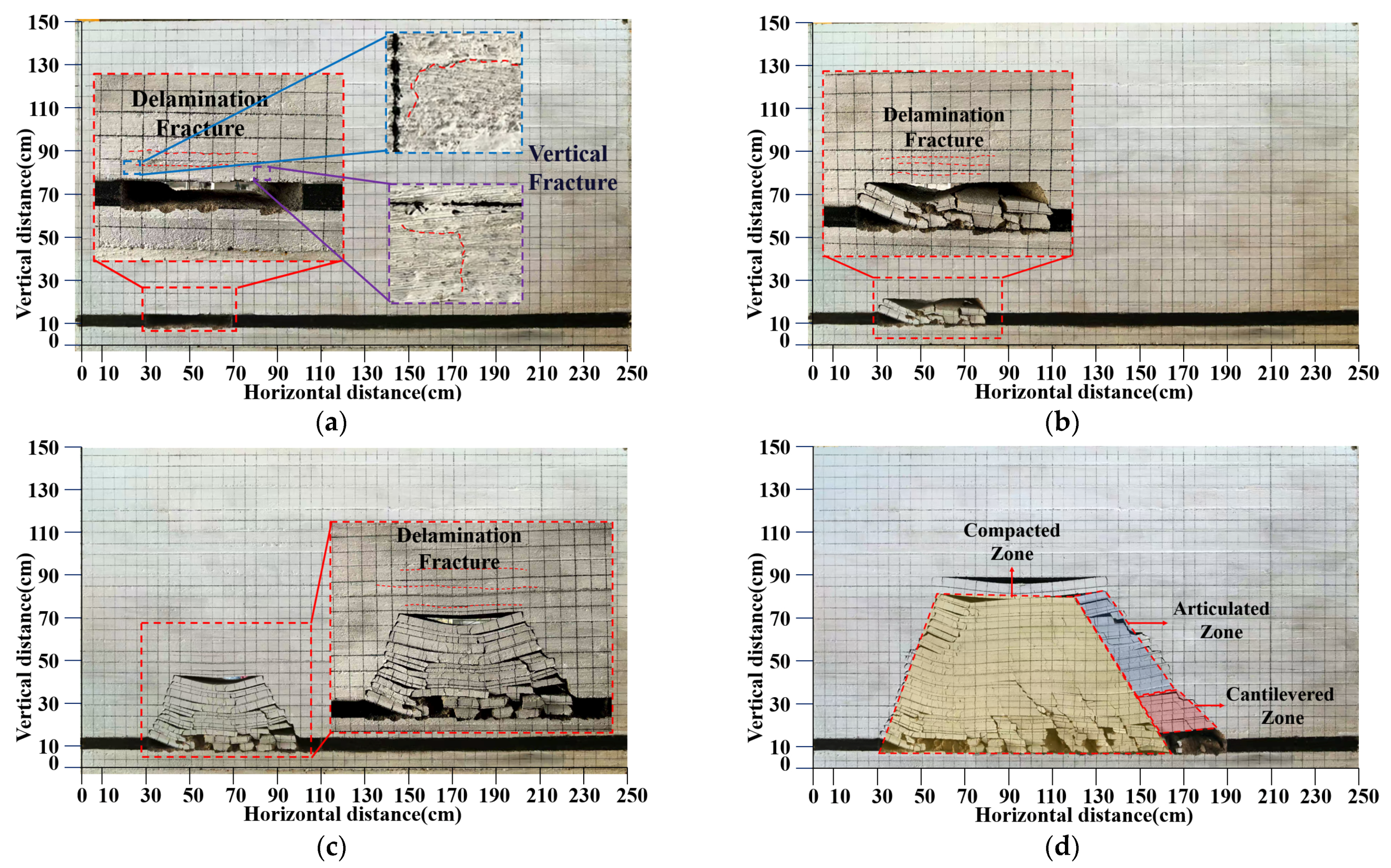
A total of 16 mining steps were carried out, each advancing 10 cm. After each mining step and stabilization, monitoring data were recorded and saved, and the next step proceeded once stability was achieved, until the working face was extracted to the designed position. The evolution of overburden movement can be divided into three distinct stages, as illustrated in Figure 3.
(1)
Early stage (Cut opening to Step 4)
During the initial excavation, the overburden remained relatively stable for the first three steps, with the main roof intact. At Step 4, the immediate roof exhibited slight bending, accompanied by two continuous horizontal separation cracks and several short vertical cracks (~2 m). This stage was characterized by initial crack initiation with limited deformation.
(2)
Middle stage (Steps 5–10)
At Step 5, the immediate roof began to collapse, and by Step 6, it had fully caved, accompanied by partial failure of the main roof, with the caving zone height reaching ~16 m. During Steps 7–8, periodic weighting induced the first large-scale collapse, expanding the caving zone to ~28 m and extending the main separation crack to ~46 m. At Steps 9–10, further large-scale roof collapses occurred, with the caving zone height increasing to ~46 m and ~61 m, respectively. This stage is characterized by progressive roof caving and rapid upward propagation of separation cracks.
(3)
Late stage (Steps 11–16)
At Step 11, the caving zone extended to ~67 m, accompanied by stepped boundary cracks. Between Steps 12 and 14, the caving height stabilized at ~67 m, while a continuous horizontal crack developed at ~74 m above the roof. During Steps 11–16, dynamic loading intensified, and periodic roof collapses occurred with an average span of ~20 m. The formation of compaction, hinged, and cantilever zones induced bending and partial breakage of the main roof, which hindered the smooth advancement of hydraulic supports and increased their loading demand.

3.2.2. Analysis of Surrounding Rock Displacement in the Working Face

In this test, DIC was used to monitor displacement during excavation. This non-contact, high-precision method captured subtle deformation fields, providing detailed data on surrounding rock instability. Excavation images were processed with PhotoInfo (version 8.1) to extract displacement data, and displacement contours were generated in PostView (version 8.1). Typical results are shown in Figure 4. Based on these maps, the deformation and failure of the overburden can be divided into three stages:
(1)
Pre-caving stage (Steps 1–4)
DIC monitoring showed only minor surface displacement during Steps 1–3, with the overburden structure remaining intact. By Step 4, localized strain concentration appeared in the immediate roof, and a horizontal crack formed within ~6 m above the seam, marking the onset of plastic deformation.
(2)
Development and upward propagation (Steps 5–10)
At Step 5, DIC images captured sudden displacement growth as the immediate roof collapsed, while transverse cracks initiated in the main roof. Between Steps 6–8, separation expanded rapidly, and bending subsidence above the main roof was clearly visible in the deformation contours. The coal wall exhibited progressive strain localization, with advanced fractures developing ahead of the face. By Steps 9–10, the caving zone extended upward to ~76 m, with displacement contours illustrating the transition from local collapse to large-scale instability.
(3)
Periodic caving stage (Steps 11–16)
During this stage, DIC results showed the caving height stabilizing at ~74 m. Periodic roof collapses occurred with ~20 m intervals, producing alternating zones of high and low displacement. Broken rock masses in the goaf formed stable hinge-like structures, while hanging roof above the coal wall created localized stress transfer points. The displacement field indicated progressive upward migration of the load-bearing zones, corresponding to intensified strata pressure.

3.2.3. Analysis of Mining-Induced Stress Variation in the Working Face

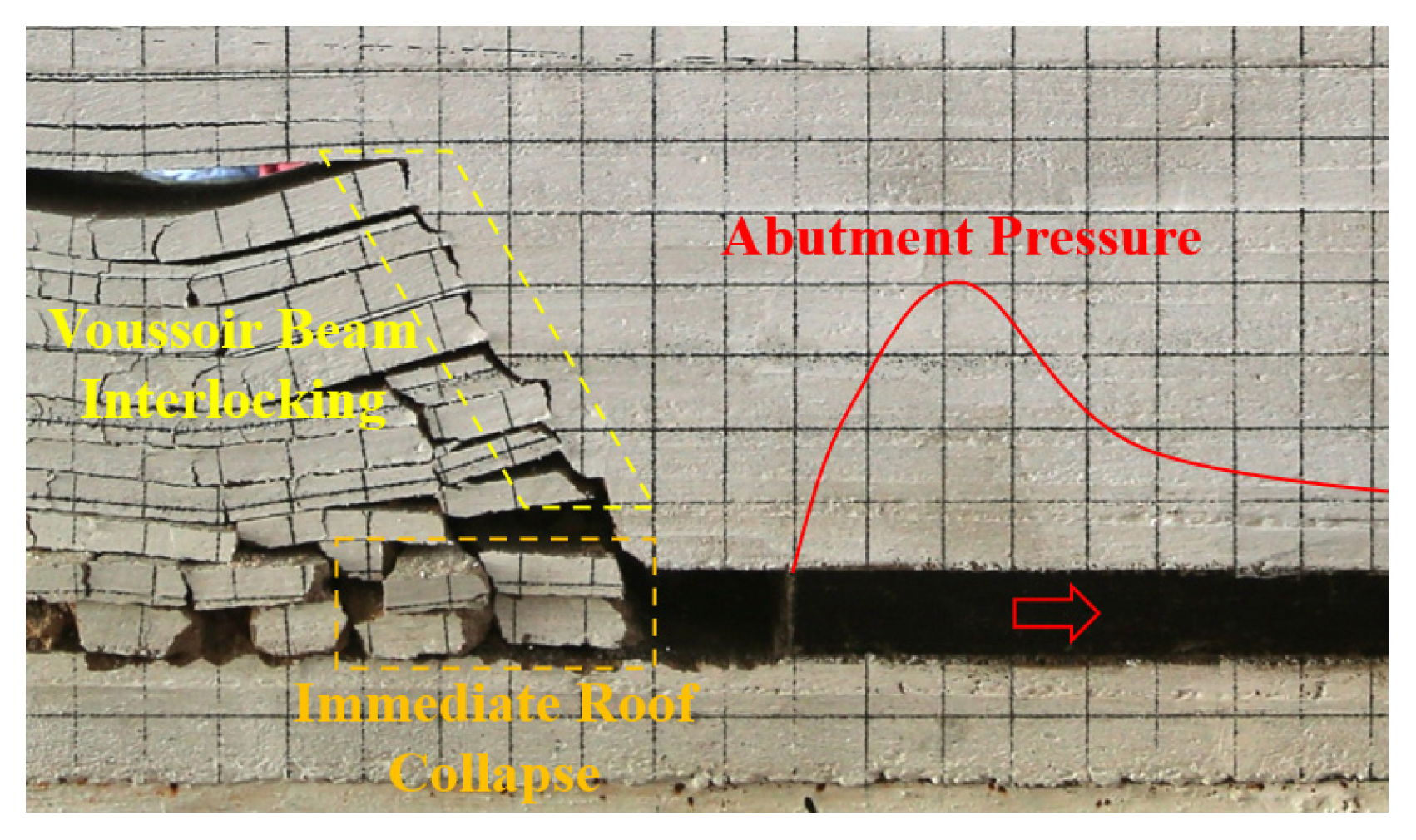
As shown in Figure 5, in the model test, the immediate roof gradually caved, and the main roof fractured as the goaf expanded. After breaking, one end of the rock beam remained clamped while the other end rotated and subsided onto the gangue, causing the overlying strata to bend and sink. A clear abutment pressure developed ahead of the face, indicating that the test realistically reproduced the surrounding rock response during face retreat.
Stress monitoring and DIC displacement analysis provide complementary views of strata response. Coal seam sensors (Figure 6) recorded vertical stress evolution, with peaks matching key roof separation and breakage events. The first sensor was placed 20 m from the excavation start to avoid sensor overcrowding. Meanwhile, DIC results (Figure 4) captured full-field displacement and crack development, showing bending, subsidence, and fracture propagation. Together, the two methods confirm a strong coupling between stress concentration and deformation: stress peaks coincide with displacement jumps, and large-scale crack connectivity corresponds to abutment pressure increase. This dual validation demonstrates that the model test reliably reproduces the mechanical behavior of surrounding rock during face retreat.
(1)
Initial stage (Steps 1–4)
During Steps 1–2, the roof remained intact with no separation observed. At Step 3, small separation cracks appeared in the immediate roof, and the abutment pressure rose from the pre-mining value of 10.8 MPa to 19.82 MPa, with a stress concentration factor of 1.84. The stress peak was located 8–15 m ahead, with an influence range of about 30–40 m. At Step 4, large-scale separation cracks developed in the immediate roof, increasing the abutment pressure to 21.82 MPa and the stress concentration factor to 2.02, while the influence range expanded to ~40 m.
(2)
Middle stage (Steps 5–10)
During Steps 5–7, the immediate and main roofs gradually collapsed, and the abutment pressure increased to 26.56 MPa with a stress concentration factor of 2.50. The stress peak remained 8–15 m ahead, while the influence range expanded to 50 m. At Step 8, an articulated voussoir beam structure formed in the overlying strata, transferring the stress peak deeper into the coal seam. Separation cracks developed above the main roof, and the pressure rose to 34.25 MPa, with a concentration factor of 3.17; the peak was located ~10 m ahead, with an influence range of 55 m. At Steps 9–10, as the caving height increased, the pressure further rose to 36.73 MPa with a concentration factor of 3.40, the peak shifted to 10–15 m, and the influence zone extended to 58 m.
(3)
Final stage (Steps 11–14)
During Steps 11–14, with the periodic collapse of the roof, the abutment pressure peak exhibited a fluctuation of “increase–decrease–increase.” The maximum stress reached 42.89 MPa with a concentration factor of 3.97, and the influence range extended beyond 60 m. At this stage, the stress concentration factor consistently remained above 3.8, indicating strong mining-induced stress. Because the immediate and main roofs were composed of thick, hard sandstone and siltstone, long cantilever structures developed, leading to pronounced mining effects characterized by high stress and wide failure zones, resulting in reduced surrounding rock stability.

3.2.4. Analysis of Roof Stress Variation

By systematically analyzing the sensor data from the main roof and the key strata, the monitoring data of the main roof can be seen in Figure 7, and those of the key stratum are given in Figure 8. The stress evolution laws during the mining process were revealed as follows:
(1)
Main roof
The vertical stress evolution of the immediate roof can be divided into three stages. During Steps 1–3, stress rose slowly from 10.35 to 12.62 MPa (concentration factor 1.22, influence range ~30 m), showing weak ground pressure. At Step 4, delamination of the immediate roof caused a sharp increase to 19.88 MPa (factor 1.92, ~35 m). During Steps 5–7, progressive caving raised stress to 18.22 MPa (factor 1.76, ~40 m). At Step 8, crack development in the key strata pushed stress to 21.07 MPa (factor 2.04). By Steps 9–10, roof collapse further increased stress to 21.65 MPa (factor 2.09, ~50 m). In Steps 11–16, large-scale periodic caving raised stress to a maximum of 24.88 MPa (factor 2.40, >50 m), indicating strong and extensive ground pressure.
(2)
Key strata
The key strata showed a similar but delayed stress response, lagging 10–20 m. During Steps 1–3, stress rose from 9.76 to 11.6 MPa (factor 1.19, ~30 m). At Step 4, immediate roof delamination raised stress to 15.46 MPa (factor 1.58, ~35 m). During Steps 5–7, stress increased from 13.03 to 14.92 MPa (factor 1.76, ~40 m). At Step 8, separation cracks raised stress to 15.79 MPa (factor 1.62). After collapse in Steps 9–10, stress reached 16.07 MPa (factor 1.65, ~50 m), while stress behind the face decreased. During Steps 11–16, large-scale caving pushed peak stress to 17.88 MPa (factor 1.83, >50 m), indicating persistent loading.
(3)
Coupled evolution and stress transfer
The immediate roof and key strata exhibited coordinated but lagged stress responses. During Steps 1–4, both showed low concentration factors (1.22 and 1.19), rising synchronously at Step 4 after delamination (1.92 and 1.58). In Steps 5–10, the key strata lagged by ~10–20 m, but both recorded stress surges at Steps 8–10. During Steps 11–16, periodic caving caused high fluctuations, stabilizing at 2.40 (roof) and 1.83 (key strata). Stress transfer showed deepening influence and delayed peaks: the affected range expanded from 30 m to >50 m, and peak positions shifted from 8–15 m to beyond 15 m. Hard siltstone and sandstone strata formed long arch-like structures, enhancing stress transfer and enlarging their range. Immediate roof collapse released stress behind the face, while delayed collapse of the key strata prolonged this effect, forming a cycle of stress transfer–release–redistribution.

4. Study on the Influence Mechanism of Coal Wall Spalling Based on Numerical Simulation

4.1. Numerical Model of Coal Wall Spalling and Fracture Evolution

4.1.1. Establishment of the Numerical Model and Mechanical Parameters

(1)
Model construction
Based on the geological conditions, a 1:1 scale UDEC numerical model (200 m × 90 m) was established for the 12306 working face, with coal pillars of 40 m width left on both sides. The top boundary of the model is free but subjected to a vertical load of 9.6 MPa to simulate the overburden pressure; lateral boundaries are horizontally fixed, and the bottom boundary is fixed in both vertical and horizontal directions, establishing plane stress conditions. The coal seam is discretized using a stochastic polygonal method, while other strata are generated as brick-shaped blocks through the block cut joint-set brick command. Lithological variations are distinguished by color fillings (Figure 9). The mechanical parameters for blocks and joints are listed in Table 3. The simulation adopts static boundary conditions, and all loads are applied quasi-statically to ensure numerical stability and equilibrium before mining steps.
(2)
Simulation scheme and parameter setting
The working face was advanced in 5 m steps (except for Section 4.2.3), with hydraulic support resistance simulated by structural elements. The criterion for coal wall spalling was defined as the extent of the plastic zone in front of the coal wall, while abutment stress was recorded at each step.
During the numerical simulation, pre-set monitoring points continuously recorded real-time data. In the physical similarity test, the abutment stress peaked at Step 8 (equivalent to 80 m advance), which corresponded to Step 16 in the numerical model. As shown in Figure 10, the numerical results agree well with the physical experiment: the peak stresses of the physical and numerical models were 34.25 MPa and 33.2 MPa, respectively, with a relative error of approximately 3.1%. The caving ranges were 28 m and 27 m, differing by about 3.6%. These discrepancies are within 5%, indicating good agreement between the physical similarity experiment and the numerical simulation, thus validating the reliability of both approaches.

4.1.2. Numerical Simulation of Coal Body Fracture Evolution

The fracture evolution of the coal wall under mining-induced stress was simulated using UDEC (Figure 11). Results show a four-stage process: (i) initiation (0–3000 steps), where sparse micro-cracks developed in shallow coal with negligible displacement; (ii) stable extension (3000–5000 steps), as cracks connected into several zones and wall displacement reached ~400 mm; (iii) accelerated propagation (5000–10,000 steps), with fractures penetrating 2–4 m, branching in a fishbone pattern, and local spalling occurring; and (iv) failure (10,000–20,000 steps), when fractures coalesced into a through-going shear plane (60–75°), inducing overall slippage, ~800 mm displacement, and large-scale spalling. This fracture evolution behavior is consistent with the Hoek–Brown failure criterion, which describes the transition from brittle to ductile behavior through strain-softening and energy dissipation. The brittle stage is characterized by micro-crack initiation and growth, while the ductile stage involves fracture propagation, coalescence, and large-scale spalling.

4.2. Numerical Simulation of Coal Wall Instability

Numerical simulations were conducted to investigate coal wall instability by considering geological factors (burial depth, mining height, dip angle) and technical factors (mining step size, support resistance). A series of UDEC models were built, and parametric analyses were performed by varying one factor at a time.

4.2.1. Effect of Mining Depth on Coal Wall Spalling

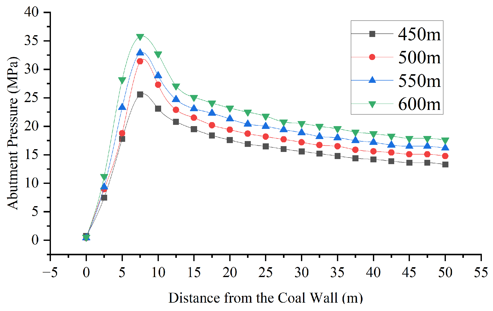
Using the 12306 panel (~500 m depth) as background, numerical models were built for burial depths of 450, 500, 550, and 600 m. With other conditions fixed, the face advanced in 5 m steps. The simulations examined the coal wall displacement and abutment pressure response under different depths.
(1)
Coal wall and roof displacement
Figure 12 illustrates the displacement fields under varying depths. The maximum horizontal displacement of the coal wall is 0.56 m, 0.73 m, 0.82 m, and 0.84 m at depths of 450 m, 500 m, 550 m, and 600 m, respectively. The zones with larger horizontal displacement are distributed at heights of 1.3 m, 1.2–1.4 m, 1.2–2.9 m, and 0.9–4.1 m above the floor. These results demonstrate that increasing depth not only enlarges the horizontal displacement but also expands the range of zones with large displacement, indicating an intensified spalling tendency.
(2)
Abutment stress distribution
The abutment stress distribution (Figure 13) shows that the peak position remains relatively constant with depth, but peak magnitude increases markedly. The maximum abutment stress rises from 25.6 MPa at 450 m to 31.4 MPa, 32.9 MPa, and 35.8 MPa at depths of 500 m, 550 m, and 600 m, respectively. This indicates that greater depth leads to stronger stress concentration ahead of the face, promoting fracture development and significantly increasing the likelihood of coal wall spalling.

4.2.2. Influence of Mining Height on Coal Wall Spalling

To investigate the effect of mining height on coal wall stability, four cases were simulated with mining heights of 5.0 m, 5.4 m, 5.8 m, and 6.2 m, while keeping other parameters constant. The analysis focused on the displacement field and advance abutment stress.
(1)
Displacement Field Evolution
As shown in Figure 14, the maximum horizontal displacement of the coal wall increases with mining height, reaching 0.92 m, 0.95 m, 1.13 m, and 1.79 m at 5.0 m, 5.4 m, 5.8 m, and 6.2 m, respectively. The zones with larger horizontal displacement are distributed at heights of 1.5–2.3 m, 0.8–2.3 m, 1.2–3.2 m, and 2.1–5.0 m above the floor. These results demonstrate that increasing mining height not only enlarges the horizontal displacement but also expands the range of zones with large displacement, indicating an intensified spalling tendency.
(2)
Advance Abutment Stress
As shown in Figure 15, the peak vertical stress rises with mining height, reaching 31.4, 34.3, 37.1, and 38.0 MPa, with peak positions at 7.5, 9.0, 12.5, and 15.0 m ahead of the wall. The corresponding concentration factors increase from 2.41 to 2.92. These results indicate that greater mining heights deepen the stress peak location, enhance stress concentration, and increase the likelihood of spalling.

4.2.3. Influence of Mining Step Size on Coal Wall Spalling

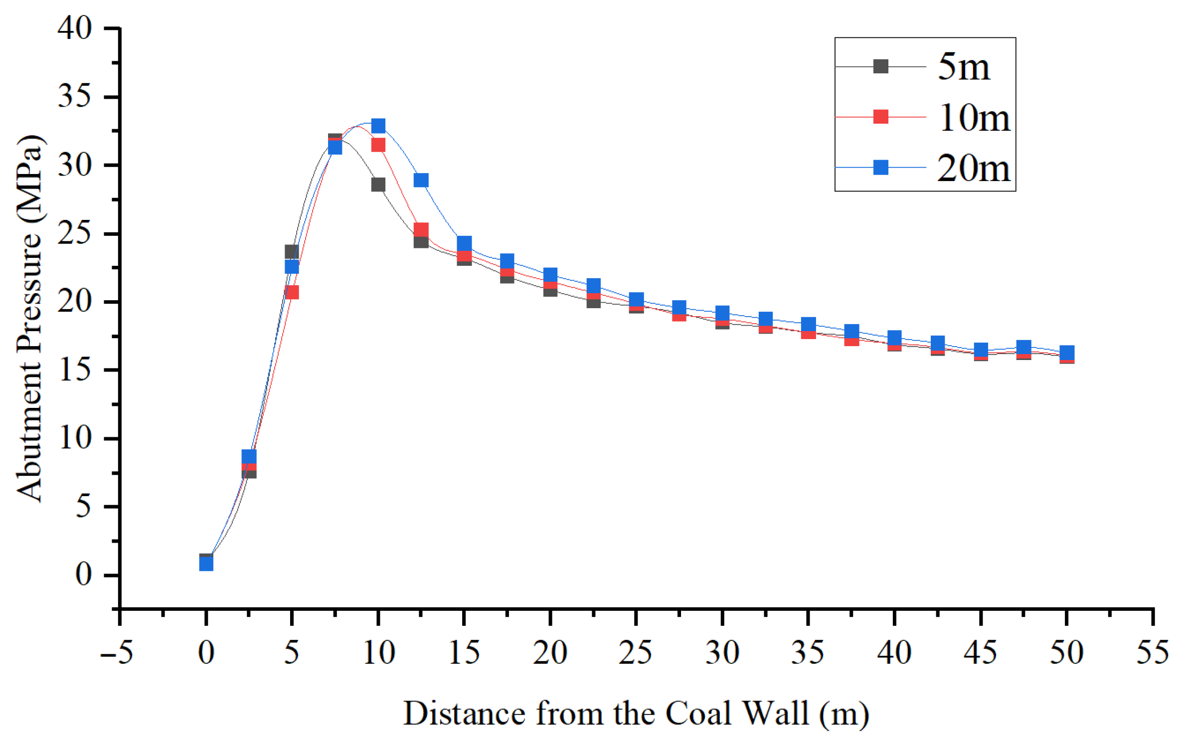
To investigate the effect of mining step size on coal wall stability, a UDEC numerical model was established, and three scenarios with different mining step sizes of 5 m, 10 m, and 20 m were simulated. By analyzing the development of the displacement field evolution and stress distribution under different mining step sizes, the mechanism of coal wall instability was revealed.
(1)
Evolution of coal wall and roof displacement
As shown in Figure 16, the distribution characteristics of horizontal displacement vary significantly under different mining step sizes. When the mining step sizes s are 5 m, 10 m, and 20 m, the maximum horizontal displacements of the coal wall reach 0.77 m, 0.83 m, and 0.95 m, respectively. The corresponding high-displacement zones are located at heights of 1.2 m, 1.2–1.4 m, and 2.4–5.1 m above the floor. These results indicate that as the mining step size increases, the expansion of the high-displacement zone is relatively limited between 5 m and 10 m, but becomes significantly more pronounced between 10 m and 20 m. This demonstrates that an excessively large mining step size (e.g., 20 m) substantially increases the risk of large-scale coal wall spalling and instability.
(2)
Distribution of advance abutment stress
As shown in Figure 17, the peak abutment stress shifts deeper into the coal mass as the mining step size increases from 5 m to 20 m. The recorded peak stresses are 31.8 MPa, 32.2 MPa, and 32.9 MPa for mining step sizes of 5 m, 10 m, and 20 m, respectively. It is worth noting that the increase in peak stress is marginal between 5 m and 10 m, but becomes more pronounced from 10 m to 20 m. This trend demonstrates that a larger mining step size not only elevates the peak stress but also extends its influence deeper into the coal wall.

4.2.4. Influence of Coal Seam Dip Angle on Coal Wall Spalling

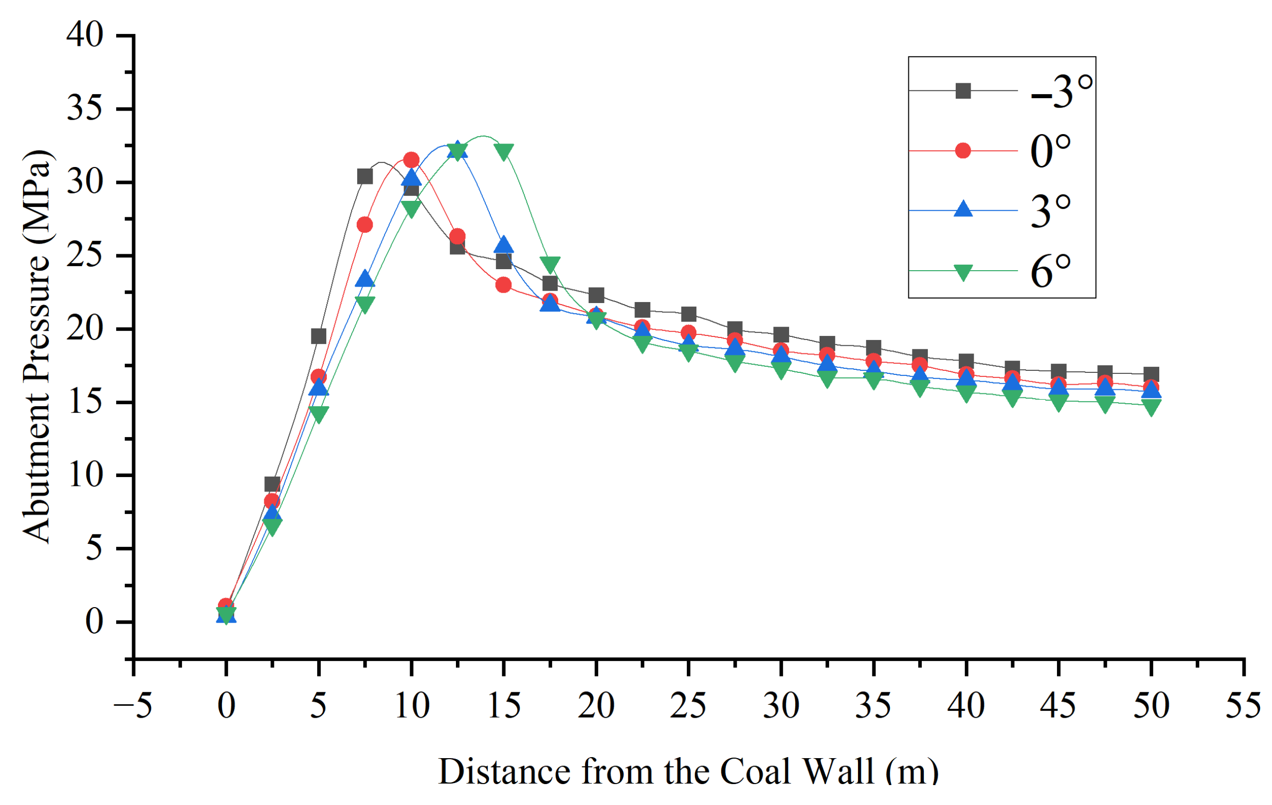
To study the effect of coal seam dip angle on coal wall stability, a UDEC model of the 12306 face was built with a 5 m mining step. Four cases were simulated with dip angles of −3°, 0°, 3°, and 6°. The plastic zone, displacement field, and stress distribution were analyzed to reveal the impact of seam inclination on stability.
(1)
Evolution of coal wall and roof displacement
As shown in Figure 18, the horizontal displacement of the coal wall varies significantly with the dip angle. The maximum displacements are 0.47 m, 0.77 m, 0.90 m, and 0.97 m at −3°, 0°, 3°, and 6°, respectively. The zones with larger displacement are located at heights of 3.4 m, 1.3–3.4 m, 1.3–4.6 m, and 1.3–4.7 m above the floor. The results show that as the dip angle increases, the displacement also increases, and the range of zones with larger displacement expands, which further increases the risk of coal wall spalling.
(2)
Distribution of advance abutment stress
As shown in Figure 19, stress distribution differs under varying dip angles. Peak stresses are 30.4 MPa, 31.5 MPa, 32.1 MPa, and 32.7 MPa at −3°, 0°, 3°, and 6°. Peak stress positions also shift deeper (8.2 m, 10.0 m, 12.5 m, and 14.0 m ahead of the wall). With increasing dip angle, peak stress rises and migrates deeper, intensifying stress concentration and enlarging the failure zone, which increases the likelihood of spalling.

4.2.5. Influence of Support Resistance on Coal Wall Spalling

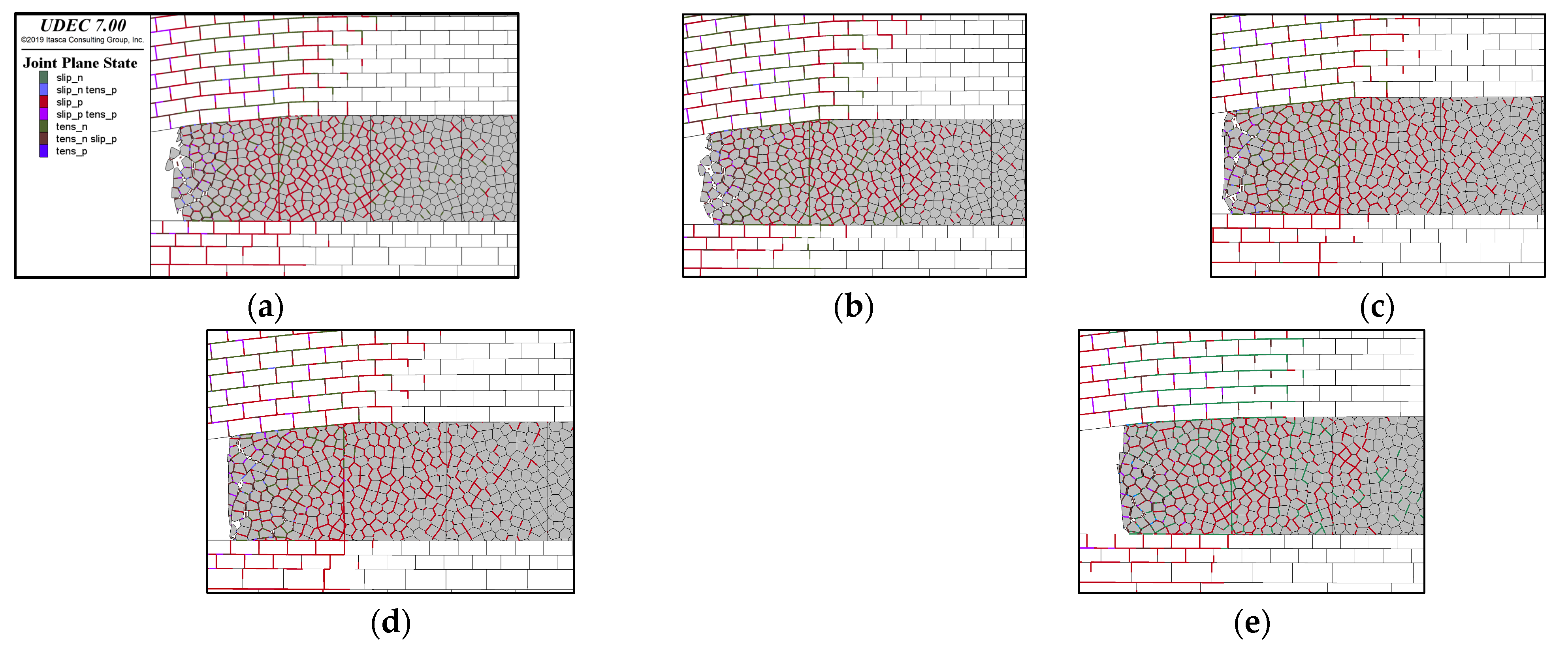
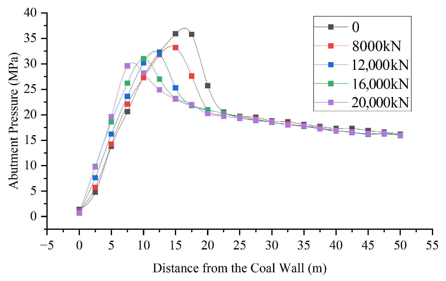
To investigate the effect of support resistance on coal wall stability, four numerical models were established with support resistances of 8000 kN, 12,000 kN, 16,000 kN, and 20,000 kN, respectively, under otherwise identical conditions. The models simulated coal wall deformation and failure during face advance with a 5 m step. By analyzing the plastic zone, displacement field, and stress distribution, the control effect and mechanism of support resistance on coal wall stability were revealed.
(1)
Development of the plastic zone
As shown in Figure 20, support resistance has a significant effect on plastic zone evolution. Without support, the plastic zone extends with a failure depth of 17.1 m and pronounced outward bulging of the coal wall toward the goaf. When support resistance increases to 20,000 kN, the plastic zone shrinks markedly, and failure depth decreases to 12.6 m. This indicates that higher support resistance reduces plastic failure and improves stability. When the support resistance exceeds 16,000 kN, the plastic failure depth decreases by approximately 25%.
(2)
Evolution of coal wall and roof displacement
As shown in Figure 21, horizontal displacement decreases with increasing support resistance. The maximum displacements are 1.21 m, 1.15 m, 0.86 m, 0.74 m, and 0.67 m, corresponding to support resistances of 0, 8000 kN, 12,000 kN, 16,000 kN, and 20,000 kN, respectively. The zones with larger displacement are located at heights of 0.9–4 m, 1.2–3.8 m, 1.6–3.6 m, 4.2 m, and 2.9 m above the floor. Increasing support resistance significantly reduces displacement and effectively controls spalling. When support resistance reaches 16,000 kN or above, the stress concentration factor decreases by about 7%, and the spalling probability is estimated to drop by more than 30%.
(3)
Distribution of advance abutment stress
As shown in Figure 22, support resistance also affects the distribution of advance abutment stress. Peak stresses are 36.5 MPa, 33.4 MPa, 32.2 MPa, 31.1 MPa, and 29.7 MPa for 0, 8000 kN, 12,000 kN, 16,000 kN, and 20,000 kN, respectively. Peak stress positions shift from 15.8 m to 8.2 m ahead of the coal wall as resistance increases. These results demonstrate that higher support resistance lowers stress concentration, suppresses plastic zone expansion, reduces failure range, and significantly decreases spalling probability. When support resistance reaches 16,000 kN or above, the stress concentration factor decreases by about 7%, and the spalling probability is estimated to drop by more than 30%, marking a practical engineering control threshold.

5. Discussion

With the increasing demand for deep coal extraction, large-mining-height technology has been widely applied in thick seams. While enhancing productivity, this method also intensifies overburden pressure and complicates surrounding rock control, particularly with coal wall spalling. Greater mining heights increase both the magnitude and duration of roof pressure, causing large-scale and deep failures. These can block shearer cutting ports, enlarge support end distances, and, under fractured roofs or delayed support, trigger roof falls and support instability. Li et al. [1,2,3] showed that once the primary key stratum destabilizes, overburden and ground movements escalate; reinforcement beneath fracture belts can suppress subsidence and delay the first weighting.
Wu et al. [7,8] described a hybrid roof evolution (cantilever → non-hinged → hinged), explaining alternating small and large periodic weighting and shifting stress peaks, which aligns with our findings. Xue et al. [9] also confirmed the influence of key strata spacing on roof stability under similar conditions.
The role of support resistance in stabilizing the coal wall has also been validated. Liang et al. [26] proposed a two-factor support design, coupling roof-bearing demands with side-wall protection. Our results confirm that increasing support resistance to ≥16,000 kN significantly reduces displacement, optimizes stress distribution, and decreases plastic failure depth and stress concentration.
Although overburden movement and coal rib spalling have been extensively studied, integrated research—especially on their coupled behavior under large-mining-height conditions—remains limited. Existing studies, such as those by Li et al. [19] and Zhang et al. [21], mostly focus on field monitoring, single-parameter simulations, or standalone laboratory tests. These do not capture the dynamic interaction between roof instability and rib failure. Our study fills this gap by integrating physical similarity modeling with UDEC simulations to investigate the coupled evolution of overburden failure, abutment pressure, and coal wall instability.
In conclusion, this study enhances the understanding of overburden movement and coal wall spalling in large-mining-height working faces, providing theoretical guidance and practical reference for safe and efficient extraction under similar geological conditions.

6. Conclusions

Based on physical similarity experiments and UDEC simulations, this study systematically investigated the mechanisms of overburden migration, ground pressure behavior, and coal wall stability in large-height longwall faces. The main findings are as follows:
Overburden failure shows a three-stage evolution. In the initial stage, the immediate roof separated, and abutment stress increased to 21.82 MPa with an influence range of ~40 m. In the middle stage, sequential key-strata collapse raised the caving height to 61 m, with peak stress reaching 36.73 MPa (factor 3.40) and the influence extending to ~58 m. In the final stage, periodic collapses with ~20 m span increased caving height to 83 m. Cantilevered main roofs imposed severe loading on the coal wall, producing a peak stress of 42.89 MPa (factor 3.97) and extending the influence beyond 60 m.
Mining stress is strongly coupled with surrounding rock deformation. Immediate roof separation (factor 2.02) and key-stratum breakage (factor 3.17) were identified as critical escalation nodes. Main roof collapse induced subsidence and fracture penetration, accelerating coal wall instability. During periodic collapse, stress fluctuations corresponded to the dynamic alternation of compaction, hinge, and cantilever zones.
Coal wall failure follows four evolutionary stages. Initial micro-fractures (<100 mm displacement) developed first, followed by stable extension (3–5 fracture zones, ~400 mm, slight bulging), accelerated connectivity (fishbone fractures, >200 mm, spalling), and final instability (shear planes inclined at 60–75°, displacement up to 800 mm), leading to large-scale instability.
Control strategies must account for multi-factor coupling. Spalling risk increases significantly when depth > 500 m and mining height > 5.8 m. An appropriate mining step size helps optimize the stress distribution and control crack propagation. Seams with dip angles > 3° require stronger support in mid–upper coal wall sections. Raising support resistance to ≥16,000 kN reduces subsidence and displacement, optimizing stress distribution. It decreases plastic failure depth by 25%, horizontal displacement by 35%, and stress concentration by 7%.
In summary, this study reveals the coupled mechanism of strata movement, stress redistribution, and coal wall instability in deep large-height mining. The results enhance understanding of surrounding rock disaster evolution and provide theoretical and engineering guidance for coal wall stability control and safe, efficient extraction under similar conditions.

Author Contributions

Conceptualization, W.F.; methodology, L.H.; software, W.F.; resources, L.H.; data curation, W.F.; writing—original draft preparation, W.F.; writing—review and editing, L.H.; funding acquisition, L.H. All authors have read and agreed to the published version of the manuscript.

Funding

This research received no external funding.

Institutional Review Board Statement

Not applicable.

Informed Consent Statement

Not applicable.

Data Availability Statement

The original contributions presented in the study are included in the article, and further inquiries can be directed to the corresponding author.

Conflicts of Interest

The authors declare no conflicts of interest.

References

  1. Hu, S.; Yu, T. Study on overlying rock movement and mine pressure behavior in shallow-buried close coal multi-seam mining. Alex. Eng. J. 2024, 105, 578–587. [Google Scholar] [CrossRef]
  2. Zhang, J.; He, M.; Shimada, H.; Wang, Y.; Hou, S.; Liu, B.; Yang, G.; Zhou, P.; Li, H.; Wu, X. Similar model study on the principle of balanced mining and overlying strata movement law in shallow and thin coal seam based on N00 mining method. Eng. Fail. Anal. 2023, 152, 107457. [Google Scholar] [CrossRef]
  3. Chen, L.; Kong, D.; Li, L.; Liu, Q.; Zhang, P.; Zhang, L.; Yujun, Z. Analysis of the impact of key strata failure on overlying strata and surface transport patterns. Eng. Fail. Anal. 2024, 163, 108532. [Google Scholar] [CrossRef]
  4. Yuan, F.; Tang, J.; Kong, L. Movement Law of Overlying Strata and Abutment Pressure Redistribution Characteristic Based on Rigid Block. Lithosphere 2022, 2022, 2520477. [Google Scholar] [CrossRef]
  5. Li, J.; Huang, Y.; Zhang, J.; Li, M.; Qiao, M.; Wang, F. The Influences of Key Strata Compound Breakage on the Overlying Strata Movement and Strata Pressure Behavior in Fully Mechanized Caving Mining of Shallow and Extremely Thick Seams: A Case Study. Adv. Civ. Eng. 2019, 2019, 5929635. [Google Scholar] [CrossRef]
  6. Ren, H.; Song, Y.; Dai, L.; Zou, J.; Zhu, C. Influence of Overlying Strata Movement on the Stability of Coal in Fully Mechanized Top-Coal Caving Mining. Appl. Sci. 2023, 13, 8470. [Google Scholar] [CrossRef]
  7. Wu, F.; Yue, X.; Yang, J.; Du, B.; Zhang, J.; Lv, B. Model of Overlying Strata Structure in Large Mining Height Excavating Condition and Calculation of Support Working Resistance. Geofluids 2022, 2022, 5894735. [Google Scholar] [CrossRef]
  8. Chai, J.; Tian, Z.; Ouyang, Y.; Liu, Y.; Zhang, D.; Yang, J. Experimental Study on Overlying Strata Movement Characteristics and Distributed Optical Fiber Characterization of Stope. J. Sens. 2022, 2022, 4016357. [Google Scholar] [CrossRef]
  9. Sun, Y.; Zuo, J.; Karakus, M.; Wen, J. A Novel Method for Predicting Movement and Damage of Overburden Caused by Shallow Coal Mining. Rock Mech. Rock Eng. 2019, 53, 1545–1563. [Google Scholar] [CrossRef]
  10. Zhang, J.; Li, X.; Qin, Q.; Wang, Y.; Gao, X. Study on overlying strata movement patterns and mechanisms in super-large mining height stopes. Bull. Eng. Geol. Environ. 2023, 82, 142. [Google Scholar] [CrossRef]
  11. Ye, Q.; Wang, W.-J.; Jia, Z.-Z.; Wang, G. Numerical simulation on tendency mining fracture evolution characteristics of overlying strata and coal seams above working face with large inclination angle and mining depth. Arab. J. Geosci. 2017, 10, 82. [Google Scholar] [CrossRef]
  12. Rong, H.; He, L.; Wei, S.; Li, J.; Wang, Y.; Wei, X.; Yang, S.; Chen, L. Overlying strata movement law and rockburst prevention & control for fully mechanized top coal caving face in extra-thick coal seams. Sci. Rep. 2025, 15, 4750. [Google Scholar] [CrossRef]
  13. Xu, X.; Kong, D.; Xiong, Y.; Chen, F. Evolution Regularity and Control Technology of Coal Face Rupture Induced by the movement of Overlying Strata Under the Influence of Mining. Min. Metall. Explor. 2023, 40, 435–452. [Google Scholar] [CrossRef]
  14. Tian, M.; Zhang, A.; Yin, D.; Xiao, H.; Han, L.; Liu, Z. Research on Mechanical Characteristics and Failure Mechanism of Coal-Rock Combined Bodies with Equal Strength. KSCE J. Civ. Eng. 2024, 28, 4678–4691. [Google Scholar] [CrossRef]
  15. Tian, M.; Han, L.; Xiao, H.; Meng, Q. Experimental study of deformations and failures of the coal wall in a longwall working face. Eng. Fail. Anal. 2021, 125, 105428. [Google Scholar] [CrossRef]
  16. Wang, J.; Zhang, Q.; Zhang, J.; Liu, H.; Zhu, G.; Wang, Y. Study on the controller factors associated with roof falling and ribs spalling in deep mine with great mining height and compound roof. Eng. Fail. Anal. 2021, 129, 105723. [Google Scholar] [CrossRef]
  17. Yao, Q.; Li, X.; Sun, B.; Ju, M.; Chen, T.; Zhou, J.; Liang, S.; Qu, Q. Numerical investigation of the effects of coal seam dip angle on coal wall stability. Int. J. Rock Mech. Min. Sci. 2017, 100, 298–309. [Google Scholar] [CrossRef]
  18. Lu, S.; Liu, S.; Wan, Z.; Cheng, J.; Yang, Z.; Shi, P. Dynamic Damage Mechanism of Coal Wall in Deep Longwall Face. Adv. Civ. Eng. 2019, 2019, 3105017. [Google Scholar] [CrossRef]
  19. Meng, G.; Zhang, J.; Wang, C.; Zhou, N.; Li, M. Analysis of Influencing Factors and Prevention of Coal Wall Deformation and Failure of Coal Wall in Caving Face with Large Mining Height: Case Study. Appl. Sci. 2023, 13, 7173. [Google Scholar] [CrossRef]
  20. Zhang, P.; Chen, Y.; Wei, Y.; Li, Z.; Dong, L. Research on Overburdened Rock Structures and Support Resistance of Shallow Buried Large Mining Heights Based on Sheet Gangs. Appl. Sci. 2025, 15, 4730. [Google Scholar] [CrossRef]
  21. Wang, S.; Li, X.; Qin, Q. Study on Surrounding Rock Control and Support Stability of Ultra-Large Height Mining Face. Energies 2022, 15, 6811. [Google Scholar] [CrossRef]
  22. Guo, W.; Li, Y.; Wang, G. The Instability Characteristics and Displacement Law of Coal Wall Containing Joint Fissures in the Fully Mechanized Working Face with Great Mining Height. Energies 2022, 15, 9059. [Google Scholar] [CrossRef]
  23. Wang, H.; Feng, L.; Zhao, Z.; Li, Y.; Cao, P.; Jiao, J.; Jiang, B.; Liu, Y. Coal-wall spalling prevention mechanism using advance-grooving pressure relief in the large-mining-height working face of a shallow coal seam. Energy Sci. Eng. 2024, 12, 5105–5118. [Google Scholar]
  24. Murmu, S.; Budi, G. Study on the Mechanism, Prediction, and Control of Coal Wall Spalling in Deep Longwall Panels Utilizing Advanced Numerical Simulation Methodology. Geofluids 2022, 2022, 5622228. [Google Scholar] [CrossRef]
  25. Xue, B.; Wang, Y.; Wang, C.; Zhang, W.; Lu, X. Quantitative research on sensitive factors of coal wall rib spalling in full mechanized caving face with large mining height. Bull. Eng. Geol. Environ. 2025, 84, 80. [Google Scholar] [CrossRef]
  26. Pang, Y.; Wang, G.; Yao, Q. Double-factor control method for calculating hydraulic support working resistance for longwall mining with large mining height. Arab. J. Geosci. 2020, 13, 252. [Google Scholar] [CrossRef]
  27. Fu, G. Research on the Stability Control Effect of Surrounding Rock in the Centralized Main Roadway Under the Influence of Mining Movement. Master’s Thesis, China University of Mining and Technology, Xuzhou, China, 2024. [Google Scholar]
  28. Zhang, L.; Wang, M.; Ren, Y.; Wang, J.; Yi, W. Experimental study on overlying strata migration law in fully mechanized top coal caving mining of extra-thick coal seam with interburden. China Min. Mag. 2025, 34, 125–133. [Google Scholar]
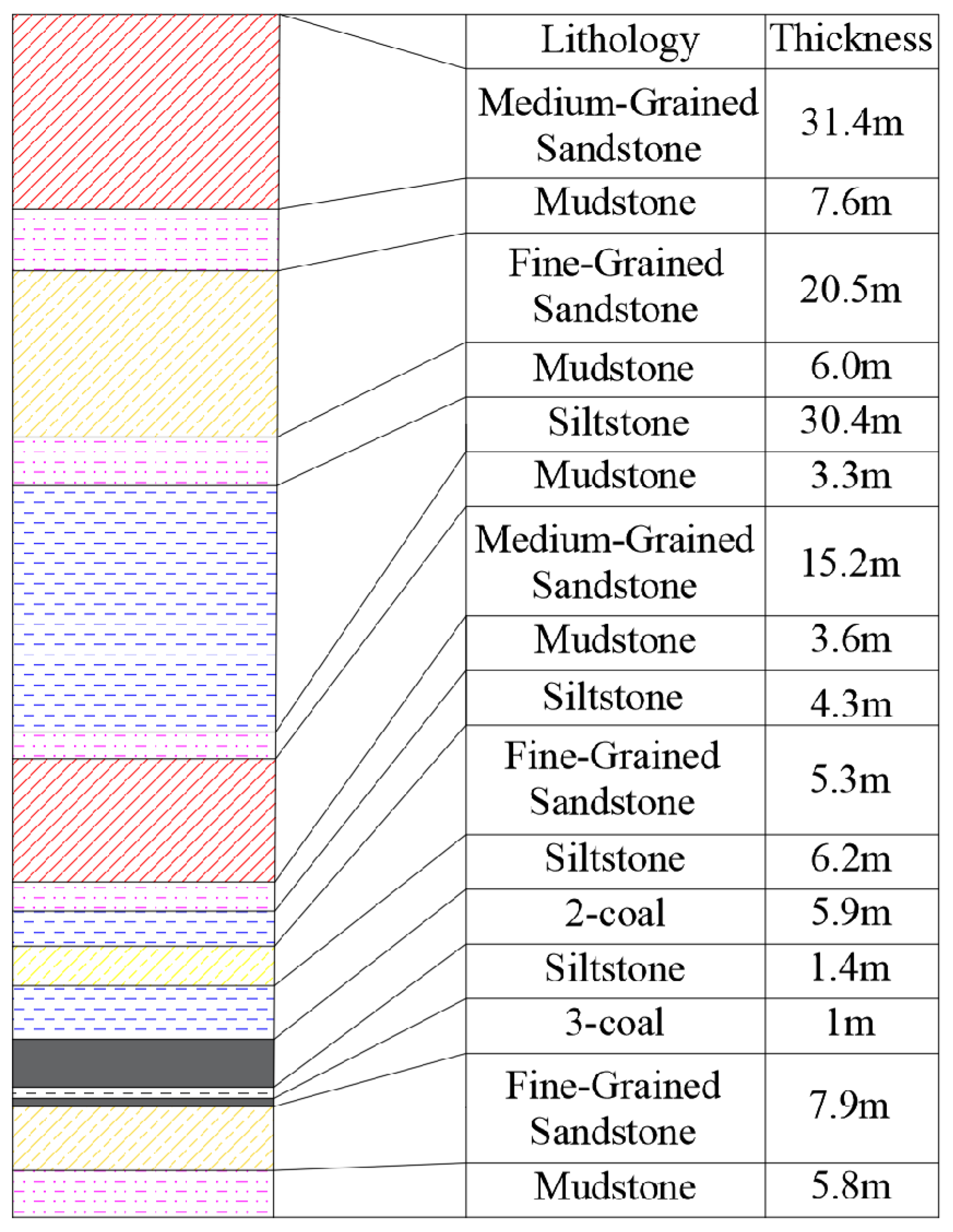
Figure 1. Stratigraphic distribution from 409.2 m to 565 m depth.
Applsci 15 12303 g001
Figure 2. Similarity experiment model and monitoring system.
Applsci 15 12303 g002
Figure 3. Three-stage evolution of overburden failure during longwall excavation: (a) Step 4—Pre-collapse stage; (b) Step 5—Immediate roof collapse; (c) Step 8—Main roof collapse; (d) Step 16—Stable caving state.
Applsci 15 12303 g003
Figure 4. Displacement contour maps of the working face during excavation. (a) Step 4; (b) Step 5; (c) Step 8; (d) Step 10; (e) Step 12; (f) Step 16.
Applsci 15 12303 g004
Figure 5. Roof collapse in the working face.
Applsci 15 12303 g005
Figure 6. Mining-induced stress distribution in the large-mining-height working face. (a) Steps 1–4; (b) Steps 5–10; (c) Steps 11–14.
Applsci 15 12303 g006
Figure 7. Vertical stress distribution of the main roof in a large-mining-height face. (a) Steps 1–4; (b) Steps 5–10; (c) Steps 11–16.
Applsci 15 12303 g007
Figure 8. Vertical stress distribution of the key strata in a large-mining-height face. (a) Steps 1–4; (b) Steps 5–10; (c) Steps 11–16.
Applsci 15 12303 g008
Figure 9. UDEC model of the 12306 large-mining-height longwall face at 1:1 scale.
Applsci 15 12303 g009
Figure 10. Comparison between similarity model and numerical simulation: (a) caving morphology; (b) abutment stress distribution.
Applsci 15 12303 g010
Figure 11. Coal body fracture evolution process. (a) 3000 steps; (b) 5000 steps; (c) 10,000 steps; (d) 20,000 steps.
Applsci 15 12303 g011
Figure 12. Effect of burial depth on coal wall displacement. (a) 450 m; (b) 500 m; (c) 550 m; (d) 600 m.
Applsci 15 12303 g012
Figure 13. Effect of burial depth on abutment stress distribution.
Applsci 15 12303 g013
Figure 14. Horizontal displacement of the coal mass under different mining heights. (a) 5.0 m; (b) 5.4 m; (c) 5.8 m; (d) 6.2 m.
Applsci 15 12303 g014
Figure 15. Advance abutment stress curves under different mining heights.
Applsci 15 12303 g015
Figure 16. Horizontal displacement of the coal mass under different mining step sizes. (a) 5 m; (b) 10 m; (c) 20 m.
Applsci 15 12303 g016
Figure 17. Advance abutment stress curves under different mining step sizes.
Applsci 15 12303 g017
Figure 18. Horizontal displacement of the coal mass under different coal seam dip angles. (a) −3°; (b) 0°; (c) 3°; (d) 6°.
Applsci 15 12303 g018
Figure 19. Advance abutment stress curves under different coal seam dip angles.
Applsci 15 12303 g019
Figure 20. Plastic zone of the coal mass under different support resistances. (a) Without support; (b) 8000 kN; (c) 12,000 kN; (d) 16,000 kN; (e) 20,000 kN.
Applsci 15 12303 g020
Figure 21. Horizontal displacement of the coal mass under different support resistances. (a) Without support; (b) 8000 kN; (c) 12,000 kN; (d) 16,000 kN; (e) 20,000 kN.
Applsci 15 12303 g021
Figure 22. Advance abutment stress curves under different support resistances.
Applsci 15 12303 g022
Table 1. Physico-mechanical parameters of the rock mass and similar materials.
Rock Mass TypeRock Mass ParametersSimilar Material Parameters
Density (g/cm3)Uniaxial Compressive Strength (MPa)Elastic Modulus (GPa)Density (g/cm3)Uniaxial Compressive Strength (MPa)Elastic Modulus (MPa)
Medium-grained sandstone2.8280.9710.771.901.32232.66
Fine-grained sandstone2.7253.907.681.921.16184.22
Siltstone2.6752.249.702.051.02156.21
Mudstone2.4916.952.471.940.35137.54
Coal1.463.250.121.930.2152.97
Table 2. Model layout scheme.
Stratum No.LithologyModel
Thickness (cm)
Ratio (River Sand/
Gypsum/Calcium Carbonate)
River Sand (kg)Gypsum (kg)Calcium Carbonate (kg)Total Dry Weight (kg)
13Medium-grained sandstone31.006:0.5:0.5372.0031.0031.00434.00
12Mudstone7.507:0.5:0.590.006.436.43102.86
11Fine-grained sandstone20.506:0.4:0.6246.0016.4024.60287.00
10Mudstone6.007:0.5:0.572.005.145.1482.29
9Siltstone30.507:0.6:0.4366.0031.3720.91418.29
8Mudstone3.507:0.5:0.542.002.632.6347.25
7Medium-grained sandstone15.006:0.5:0.5180.0015.0015.00210.00
6Mudstone3.507:0.5:0.542.002.632.6347.25
5Medium-grained sandstone4.506:0.5:0.554.004.504.5063.00
4Fine-grained sandstone5.006:0.4:0.660.004.006.0070.00
3Siltstone6.507:0.6:0.478.006.694.4689.14
22-coal6.008:0.5:0.572.004.504.5081.00
1Floor strata10.56:0.4:0.6126.008.4012.60147.00
Table 3. Strata Parameters for Numerical Simulation.
Strata No.LithologyThickness (m)Density (g·cm−3)Elastic Modulus (GPa)Poisson’s RatioInternal Friction Angle (°)Cohesion (MPa)Tensile Strength (MPa)
12Siltstone30.4 m2.488.20.20354.55.8
11Mudstone3.3 m2.455.00.24303.23.0
10Medium-grained sandstone15.2 m2.58.80.19344.05.0
9Mudstone3.6 m2.455.00.24303.23.0
8Medium-grained sandstone4.3 m2.58.80.19344.05.0
7Fine-grained sandstone4.9 m2.509.30.18365.06.0
6Siltstone6.6 m2.488.20.20354.55.8
52-coal5.9 m1.402.00.30251.51.8
4Siltstone1.4 m2.488.20.20354.55.8
33-coal1.0 m1.402.00.30251.51.8
2Fine-grained sandstone7.9 m2.509.30.18365.06.0
1Mudstone5.8 m2.455.00.24303.23.0
Disclaimer/Publisher’s Note: The statements, opinions and data contained in all publications are solely those of the individual author(s) and contributor(s) and not of MDPI and/or the editor(s). MDPI and/or the editor(s) disclaim responsibility for any injury to people or property resulting from any ideas, methods, instructions or products referred to in the content.