Article

A Robust Predefined Performance Controller for Reusable Launch Vehicles Under Mismatched Disturbance and Input Saturation

1
School of Astronautics, Harbin Institute of Technology, Harbin 150001, China
2
Beijing Institute of Electronic System Engineering, Beijing 100854, China
3
Shenyang Aircraft Design and Research Institute, Aviation Industry Corporation of China, Ltd., Shenyang 110035, China
*
Author to whom correspondence should be addressed.
Appl. Sci. 2025, 15(22), 12251; https://doi.org/10.3390/app152212251
Submission received: 9 October 2025 / Revised: 28 October 2025 / Accepted: 31 October 2025 / Published: 18 November 2025

Abstract

This paper addresses the attitude tracking control issue for reusable launch vehicles (RLVs) in the presence of non-matching disturbances and saturation effects. An enhanced predefined performance function (PPF) is derived based on a novel anti-saturation predefined-time compensator (ASPC) to ensure stability during saturation. Additionally, a fixed-time disturb observer (DO) is introduced for estimating both mismatch and matching perturbations within a fixed-time interval. Based on the error transformation, a fixed-time dynamic surface control (DSC) is proposed, ensuring that the transformed system state converges to the residual set at the origin promptly. The simulations demonstrate that the attitude tracking error reliably converges to a predefined region within a predetermined time.

1. Introduction

Reusable launch vehicles have been highly valued and extensively studied by the world’s space powers due to their advantages of low-cost and high-efficiency round trips between Earth and space [1]. The re-entry stage, as a crucial stage in the RLV mission sequence, is the key to ensuring controllable recovery and reuse, while the attitude control system is essential for the safe and reliable completion of the re-entry flight. However, the vehicle model exhibits strong nonlinear and coupled characteristics, and the model parameter uncertainty is high [2]. Moreover, the re-entry flight environment is complex and experiences significant internal and external disturbances; thus, the control system needs to have strong anti-interference ability and robustness. In addition, during the re-entry phase, drastic changes in the attitude angle can easily lead to actuator saturation issues, greatly increasing the difficulty of control system design.
In order to solve the above control problems, a variety of control methods have been applied to reusable carriers in the past decade, such as gain-scheduling control [3,4], back-stepping control [5,6,7], sliding mode control [8,9,10], fuzzy control [11,12], and intelligent control methods [13,14]. However, although traditional RLV attitude control methods can better ensure the stability and robustness of vehicle attitude control, they often neglect the dynamic quality of the RLV attitude control system. With the continuous improvement in aircraft control accuracy and control quality requirements, predefined performance control has recently gained significant attention in RLV attitude control. Its main idea is to artificially set the performance envelope for the state of the controlled system, and to characterize the dynamic and steady-state performance of the controlled system by the convergence characteristics of the performance envelope function [15]. In Ref. [16], the concept of a finite-time performance function was proposed for the finite-time tracking control issue of a strictly feedback nonlinear system under uncertainties, ensuring that the system tracking error achieves the desired dynamic and steady-state performance within a finite time. Ref. [17] is based on a back-stepping control approach, in which at each step of the back-stepping design, a preset performance function is constructed to keep the vehicle tracking error within specified boundaries, thereby ensuring the required dynamic and steady-state performance of the velocity and altitude control subsystems. Ref. [15] investigated the stable tracking control problem of the vehicle preset performance under actuator failure and aerodynamic uncertainty by designing dynamic back-stepping controllers and robust adaptive back-stepping controllers for the velocity and altitude subsystems. However, this predefined performance control method can generate very large control gains near the predefined performance boundary, potentially leading to actuator saturation. This is highly dangerous for RLV attitude control and poses a significant risk of vehicle destabilization. Additionally, external uncertainties and perturbations significantly degrade the performance of the method.
In order to attenuate the effects of disturbances on vehicle attitude control, a large number of studies adopted the design of disturbance observers to observe and compensate for the disturbances. Ref. [18] proposes a finite-time disturbance observer to estimate model uncertainty and external disturbances. In Ref. [19], a method based on a fuzzy perturbation observer was proposed. This method uses fuzzy estimation and observation errors for perturbation estimation and combines a perturbation observer based on a fuzzy logic system with an adaptive sliding mode control algorithm, effectively improving the robust tracking and control of re-entry attitude. Ref. [20] combines neural network dynamic surface control with a learning function and a nonlinear perturbation observer to solve the problem of stable tracking control of aircraft under the influence of uncertain and time-varying perturbations.
However, most existing methods achieve only asymptotic or finite-time convergence of attitude errors, and when the initial error is large, the convergence time increases, which cannot meet the demand for a fast response to attitude during RLV re-entry flight. Furthermore, the existing studies have considered only the matching perturbations from external sources, and the effect of non-matching perturbations on the attitude stabilization flight of RLVs has not yet been investigated. At the same time, although our previous research [21] has conducted certain studies on the preset performance control of RLVs, during flight, saturation issues may cause flight errors to exceed the preset performance boundaries, leading to ambiguity problems. This is also the aspect in which this paper extends beyond previous studies.
Motivated by the aforementioned limitations of existing methods, a controller featuring a novel anti-saturation predefined-time compensator (ASPC)-based PPF, a fixed-time DO in concise form, and a fixed-time DSC is proposed for RLVs under mismatched disturbance and input saturation. The attitude tracking errors converge to the predefined region in a predefined time, which is determined by one parameter. Compared with the existing works, the main contributions of this paper are shown as follows:
(1)
A novel ASPC is used to adjust the value of the PPF under actuator saturation. Compared with the existing PPC, the modified PPF can reduce the predefined performance to maintain the attitude tracking error within its range when actuator saturation occurs. Moreover, after the saturation process ends, the compensator decreases within a predefined time interval.
(2)
A novel fixed-time DO is constructed to estimate both matched and mismatched disturbances during the RLV re-entry process. The proposed fixed-time DO is concisely formed, and its estimation errors can converge to zero within a fixed-time interval.
(3)
A novel fixed-time DSC method, based on the fixed-time DO, is developed to enhance the robust performance of the RLV control system. A nonlinear first-order filter is adopted to avoid the “explosion of complexity” problem and ensure the fixed-time stability of the control system.
Notation 1.
Throughout this paper, · represents the Euclidean norm and sign denotes the sign function. The matrices or vectors are given as A = A i j , A + = max A i j ,   0 and A = A + A , i , j > 0 . x = x 1 , x 2 , , x n T represents a vector while sig a x = x 1 a sign ( x 1 ) ,   x 2 a sign ( x 2 ) , ,   x n a sign ( x n ) T and x a = x 1 a ,   x 2 a , ,   x n a T .

2. Problem Formulation and Preliminaries

2.1. Problem Formulation

The mathematical model of the RLV considered in this paper is presented in [22] and written as follows:
α ˙ = sin σ cos β ψ ˙ cos γ θ ˙ sin ψ sin γ + ( φ ˙ + ω E ) ( cos θ cos ψ sin γ sin θ cos γ ) cos σ cos β γ ˙ θ ˙ cos ψ ( φ ˙ + ω E ) cos θ sin ψ p cos α tan β + q r sin α tan β β ˙ = p sin α r cos α + sin σ γ ˙ θ ˙ cos ψ + ( φ ˙ + ω E ) cos θ sin ψ + cos σ ψ ˙ cos γ θ ˙ sin ψ sin γ ( φ ˙ + ω E ) ( cos θ cos ψ sin γ sin θ cos γ ) σ ˙ = p cos α cos β q sin β r sin α cos β + α ˙ sin β ψ ˙ sin γ θ ˙ sin ψ cos γ + ( φ ˙ + ω E ) ( cos θ cos ψ cos γ + sin θ sin γ ) p ˙ = J z z M x J x x J z z J x z 2 + J x z M z J x x J z z J x z 2 + ( J x x J y y + J z z ) J x z J x x J z z J x z 2 p q + ( J y y J z z ) J z z J x z 2 J x x J z z J x z 2 q r + d p q ˙ = M y J y y + J x z ( r 2 p 2 ) J y y + ( J z z J x x ) J y y p r + d q r ˙ = J x z M x J x x J z z J x z 2 + J x x M z J x x J z z J x z 2 + ( J x x J y y + J x z ) J x z J x x J z z J x z 2 p q + ( J y y J z z J x x ) J x z J x x J z z J x z 2 q r + d r
where γ represents the flight path angle and ψ represents the heading angle. σ , β , and α denote the bank, sideslip, and attack angle, respectively. The roll, yaw, and pitch angular rates are p , r , and q , respectively. The longitude and the latitude are φ and θ , respectively. The Earth’s rotation velocity is ω E , M i i = x , y , z denotes the external lumped moment, while the moment of inertia is J i j ( i = x ,   y ,   z   ;   j = x ,   y ,   z ) . Defining ω = p ,   q ,   r T and Λ = α ,   β ,   σ T , we can obtain
Λ ˙ = R ω + Δ f J ω ˙ = Ω J ω + M a i r + M c + Δ d
where Δ f and Δ d are the mismatched and matched disturbances, respectively. J R 3 × 3 represents the inertia matrix, and the control moment is M c R 3 , where M c = B 1 u . B 1 = q 0 S r L r diag m x u 1 , m y u 2 , m z u 3 is the control moment matrix. q 0 = 0.5   ρ V 2 , in which ρ is the air density and V denotes the velocity. m x u 1   m y u 2 and m z u 3 represent the efficiency of the actuator. The control input u = u 1 , u 2 , u 3 T is
u i = v l i if u i < v l i u i else i = 1 , 2 , 3 v u i if u i > v u i
where v l = v l 1 , v l 2 , v l 3 T and v u = v u 1 , v u 2 , v u 3 T are known constants representing constraints on u . M a i r , R and Ω are denoted as follows:
M a i r = m x p L r V + m x β β q 0 S r L r m y q L r V + m y α α q 0 S r L r m z r L r V + m z β β q 0 S r L r
R = cos α tan β 1 sin α tan β sin α 0 cos α cos α cos β sin β sin α cos β
Ω = 0 r q r 0 p q p 0
where m x p , m y q , and m z r denote the damping moment coefficients, and the static stability moment coefficients in three channels are m x β , m y α , and m z β . L r and S r stand for the reference length and reference area of the RLV, respectively.
Remark 1.
Errors occur when the RLV’s navigation system is used to measure real-time position, velocity, and attitude information. Moreover, the additional items produced by the coordinate transformation also affect the accuracy of the attitude control. Therefore, the value of Δ f , which is ubiquitous in the re-entry dynamics of the RLV, cannot be ignored.
In accordance with the guidance command Λ c = α c , β c , σ c T , the following new variables are defined:
e ˙ 1 = e 2 + Δ f e ˙ 2 = H + B u Λ ¨ c + Δ d 1
where e 1 = Λ Λ c , e 2 = R ω Λ ˙ c , H = R ˙ ω R J 1 Ω J ω + R J 1 M a i r , B = R J 1 B 1 , and Δ d 1 = R J 1 Δ d .

2.2. Preliminary

Consider an autonomous dynamical system:
x ˙ = f x ;   φ ,   x 0 = 0
where x R n denotes the state, and f : R n R n is a nonlinear, locally Lebesgue-integrable function. φ R l represents the tunable parameters.
Definition 1.
According to [22], the origin of Equation (8) is considered globally stable in a predefined time if for any T c R + , there exists some φ R l , such that x t = 0 holds for t T c regardless of x t 0 .
Definition 2.
According to [23], a smooth function ρ t : R + R + is called a PPF if
(1) 
ρ t  is positive and decreasing.
(2) 
ρ 0 = ρ 0  and ρ T f = ρ , where T f is a predefined time parameter.
(3) 
ρ t  has continuous first- and second-order derivatives with respect to time.
In this paper, the following PPF is chosen:
ρ t = a 1 + a 2 arctan t T f + a 3 e k t T f + a 4 e k t T f 2   ,   0 t T f ρ ,   t > T f
a 1 = ρ 0 + 3 a 4 ,   a 2 = 4 k e k a 4 a 3 = 4 a 4 ,   a 4 = ρ ρ 0 3 π k e k 3 e k
where k satisfies 0.5 < k < 3 .
Lemma 1.
According to [24], suppose a Lyapunov function V x : R n R 0 exists such that
V ˙ x α V p x β V g x + ϑ
where α > 0 , β > 0 , 0 < p < 1 , g > 1 and ϑ 0 . Then, this system is globally stable within a fixed time T < 1 α ϑ 1 p + 1 β ϑ g 1 , and the convergence region is
lim t T x V min α 1 / p ϑ 1 ϑ 1 / p , β 1 / p ϑ 1 ϑ 1 / g
Lemma 2.
According to [25], let 0 p < 1 , μ > 0 and V x : R n R 0 be a radially unbounded Lyapunov function. If for any T c > 0 , there exist some tunable parameters φ such that V ˙ x along the trajectories of the system satisfy:
V ˙ x V x p μ + V x 2 p 1 p μ T c ,   for   x R n \ { 0 }
then x = 0 can be achieved within the predefined time T c .
Lemma 3.
According to [26], for system (8), if there exists a radially unbounded Lyapunov function V x : R n R 0 such that
V ˙ x π a T p V 1 a 2 x + V 1 + a 2 x
where T p > 0 , 0 < a < 1 . Then, this system is globally predefined time stable within a predefined time T p .
Lemma 4.
According to [27], for any constants γ ¯ > 0 and y i > 0 i = 1 ,   2 ,   ,   n , the following holds:
i = 1 n y i γ ¯ n 1 γ ¯ i = 1 n y i γ ¯ ,   if   γ ¯ > 1 i = 1 n y i γ ¯ i = 1 n y i γ ¯ ,   if   0 < γ ¯ 1
Assumption 1.
It is assumed that the mismatched disturbance Δ f and the matched disturbance Δ d 1 are bounded. For example, there exist δ d and δ f such that Δ f δ f and Δ d 1 δ d are satisfied, where δ d and δ f are boundaries.
Assumption 2.
For all t > 0 , the expected command Λ c is a sufficiently smooth function of t , and Λ c , Λ ˙ c , Λ ¨ c are bounded. Such that Λ c + Λ ˙ c + Λ ¨ c A c , where A c is a positive constant.
Remark 2.
During the RLV re-entry phase, the expected command is generated under the precondition of considering constraints and its own spatial position, meaning that the measured values of Λ ˙ c and Λ ¨ c are difficult to obtain in practical systems. Meanwhile, the first and second derivatives of Λ c can exist and be bounded by designing Λ c . Considering this, we can utilize the fixed-time DO to estimate Δ d 1 Λ ¨ c instead of Δ d 1 .

3. Control System Design

3.1. Prescribed Performance Function with Anti-Saturation Compensator and Error Transformation

The boundary constraint of the attitude tracking error is designed as
ρ l < e 1 < ρ u
where ρ u = ρ 0 u + m 1 u , ρ l = ρ 0 l + m 1 l . ρ 0 u = ρ 0 u 1 , ρ 0 u 2 , ρ 0 u 3 T , ρ 0 l = ρ 0 l 1 , ρ 0 l 2 , ρ 0 l 3 T . ρ 0 u i and ρ 0 l i are the desired performance functions, as described in Definition 2, i = 1 ,   2 ,   3 . m 1 u and m 1 l are the ASPCs designed in Section 3.2.
To restrict the attitude tracking error by the PPF, an error transformation is incorporated, modulating the attitude tracking error e 1 .
z 1 = tan π e 1 0.5 ρ u ρ l ρ u + ρ l
Hence, the error transformation function (17) satisfies the following properties:
lim z 1 e 1 = ρ u ,   lim z 1 e 1 = ρ l
Taking the time derivative of Equation (17), we obtain
z ˙ 1 = Γ diag π ρ u i + ρ l i e ˙ 1 + Γ diag π e 1 i π ρ l i ρ u i + ρ l i 2 ρ ˙ u + Γ diag π e 1 i + π ρ u i ρ u i + ρ l i 2 ρ ˙ l
where i = 1 , 2 , 3 and Γ = diag 1 + tan 2 π e 1 i 0.5 ρ u i ρ l i ρ u i + ρ l i .

3.2. Anti-Saturation Predefined-Time Compensator Design

The conventional PPFs in Refs. [28,29] are predefined and cannot be adjusted during the re-entry process. The prerequisite for the application of these methods is that the control moment can be accurately provided, which is unreasonable for the actual RLV control system. Because the amplitude of the RLV rudder’s swing is limited, inappropriate initial conditions or unsatisfactory external disturbances may render conventional PPFs infeasible under input saturation. In this paper, a novel ASPC is proposed to modify the boundary value of the PPF. Thus, the attitude tracking error is also guaranteed to remain within the range of the performance function in the presence of input saturation. Meanwhile, the compensator vanishes within the predefined time interval after the saturation process ends, avoiding long-term impacts on the PPF and attitude tracking.
The novel ASPC is defined as follows:
m ˙ 1 u = diag μ + m 1 u i 2 a m m 1 u a m 1 a m T m μ + diag ρ u i + ρ l i e 1 i + ρ l i p ¯ m 1 u + m 2 l m ˙ 2 u = π a m T m m 2 u 1 a m / 2 + m 2 u 1 + a m / 2 + w 2 u m ˙ 1 l = diag μ + m 1 l i 2 a m m 1 l a m 1 a m T m μ + diag ρ u i + ρ l i ρ u i e 1 i p ¯ m 1 l + m 2 u m ˙ 2 l = π a m T m m 2 l 1 a m / 2 + m 2 l 1 + a m / 2 + w 2 l
where p ¯ = diag p i i , p i i > 0 . m i j = m i j 1 m i j 2 m i j 3 T , i = 1 , 2 , j = u , l . w 2 l = B + m 3 u + B m 3 l , w 2 l = B m 3 u + B + m 3 l , m 3 u = v + u + , m 3 l = v u , 0 < a m < 1 , μ > 0 , T m > 0 . The initial values of variables in Equation (20) satisfy m 1 u 0 = 0 , m 1 l 0 = 0 , m 2 u 0 = 0 , m 2 l 0 = 0 .
Theorem 1.
Considering the RLV control system, the PPF is designed as Equation (16) and the ASPC is given by Equation (20). Suppose there exists a positive number δ m k > 0 and the inequality v k u k δ m k holds for all t 0 , k = 1 , 2 , 3 . Then, 0 m 1 j λ 1 m , 0 m 2 j λ 2 m , j = u , l , where λ 1 m and λ 2 m are bounded positive parameters. Moreover, the proposed compensator can converge to zero within a predefined time 2 T m when m 3 u = m 3 l = 0 .
Proof. 
Considering the definitions of m 3 u , m 3 l and Equation (20), we obtain m i j 0 when m i j k 0 0 , i = 1 ,   2 , j = u ,   l , k = 1 ,   2 ,   3 . With the inequality v i u i δ m i , we can obtain w 2 u ,   w 2 l b ¯ max δ m k , b ¯ = max B i i ,   i = 1 ,   2 ,   3 , and the derivative of m 2 j satisfies
m ˙ 2 j π a m T m m 2 j 1 a m / 2 + m 2 j 1 + a m / 2 + b ¯ max δ m k
m 2 j evolves strictly within the region 0 , and m 2 j 1 a m / 2 + m 2 j 1 + a m / 2 tends to monotonically increase. Then, there exists a positive number λ 2 m satisfying m ˙ 2 j k 0 when m 2 j k λ 2 m , which indicates 0 m 2 j k λ 2 m , j = u ,   l , k = 1 ,   2 ,   3 .
After the saturation phenomenon disappears, m ˙ 2 j becomes:
m ˙ 2 j π a m T m m 2 j 1 a m / 2 + m 2 j 1 + a m / 2
m 2 j will converge to zero in the time interval T m based on Lemma 3.
Similarly, there exists a positive number λ 1 m satisfying m ˙ 1 j k 0 when m 1 j k λ 1 m , which indicates 0 m 1 j k λ 1 m , j = u ,   l , k = 1 ,   2 ,   3 . After the disappearance of the saturation phenomenon and m 2 j vanishes to zero within the time T m , we obtain
m ˙ 1 j m 1 j a m μ + m 1 j 2 a m 1 a m T m μ
According to Lemma 2, the supreme time consumption for m 1 j vanishing to zero equals T m , which indicates ρ u and ρ l of the PPF are equal to ρ 0 u and ρ 0 l respectively, avoiding long-term impacts on the PPF and attitude tracking. This completes the proof of Theorem 1. □

3.3. Fixed-Time Disturbance Observer

To estimate the mismatched and matched disturbances, the novel fixed-time DO is proposed in this subsection. Firstly, the RLV control system (7) is rewritten into the following form:
e ˙ 1 = g 1 e 1 + f e s + τ 1 e ˙ 2 = g 2 e 2 + d e s + τ 2
where d e s = g 2 e 2 + Δ d 1 , f e s = g 1 e 1 + Δ f , τ 1 = e 2 , τ 2 = H + B u Λ ¨ c . g 1 and g 2 are positive diagonal matrices.
The following auxiliary system is introduced:
e ^ ˙ 1 = g 1 e ^ 1 + τ 1 e ^ ˙ 2 = g 2 e ^ 2 + τ 2
where e ^ 1 and e ^ 2 are the measurable states.
Theorem 2.
Define Δ 1 = e 1 e ^ 1 and Δ 2 = e 2 e ^ 2 , if the fixed-time DO is designed as
Δ ^ ˙ 1 = g 1 Δ ^ 1 + k 1 diag e Δ 1 i λ e Δ 1 i 2 1 + μ e Δ 1 i 2 sign e Δ 1 Δ ^ ˙ 2 = g 2 Δ ^ 2 + k 2 diag e Δ 2 i λ e Δ 2 i 2 1 + μ e Δ 2 i 2 sign e Δ 2
and the estimations of the mismatched and the matched disturbances are given by
f ^ = g 1 e 1 + g 1 e Δ 1 + k 1 diag e Δ 1 i λ e Δ 1 i 2 1 + μ e Δ 1 i 2 sign e Δ 1 d ^ 1 = g 2 e 2 + g 2 e Δ 2 + k 2 diag e Δ 2 i λ e Δ 2 i 2 1 + μ e Δ 2 i 2 sign e Δ 2
where k 1 > δ f e e λ / 2 e e , k 2 > δ d e e λ / 2 e e , i = 1 ,   2 ,   3 . e e is the natural exponential. λ > 0 , μ > 0 and Θ = λ 1 + μ > 1 . Thereby, the observer errors e Δ 1 = Δ 1 Δ ^ 1 , e Δ 2 = Δ 2 Δ ^ 2 and the estimation errors e f = Δ f f ^ , e d 1 = Δ d 1 d ^ 1 are fixed-time stable. In other words, there exist positive numbers T f o d and T d satisfying e Δ 1 = 0 , e f = 0 for all t > T f o d and e Δ 2 = 0 , e d 1 = 0 for all t > T d , respectively.
Proof. 
To prove that e Δ 2 = 0 and e d = 0 when t > T d , we take the derivative of e Δ 2
e ˙ Δ 2 = Δ ˙ 2 Δ ^ ˙ 2 = d e s g 2 e Δ 2 k 2 diag e Δ 2 i λ e Δ 2 i 2 1 + μ e Δ 2 i 2 sign e Δ 2
Choose a positive-definite Lyapunov function candidate V Δ 2 = e Δ 2 T e Δ 2 , then we obtain
V ˙ Δ 2 = 2 e Δ 2 T e ˙ Δ 2 = 2 e Δ 2 T d e s g 2 e Δ 2 k 2 diag e Δ 2 i λ e Δ 2 i 2 1 + μ e Δ 2 i 2 sign e Δ 2 2 i = 1 3 k 2 e Δ 2 i λ e Δ 2 i 2 1 + μ e Δ 2 i 2 + 1 + e Δ 2 i d e s i
When V Δ 2 > 1 , we have λ e Δ 2 i 2 1 + μ e Δ 2 i 2 + 1 λ 1 + μ + 1 > 2 , i = 1 , 2 , 3 . Thereby, we obtain
V ˙ Δ 2 2 i = 1 3 k 2 + δ d e Δ 2 i Θ + 1 2 k 2 + δ d V Δ 2 Θ + 1 2
Considering k 2 > δ d e e λ / 2 e , we obtain k 2 δ d > 0 and 1 / 2 k 2 + δ d V Δ 2 Θ + 1 2 d V Δ 2 d t . Letting t 0 = 0 , we can conclude that all the solutions starting from V Δ 2 1 reach the set V Δ 2 < 1 in a fixed-time T d 1 1 / k 2 δ d Θ 1 .
When V Δ 2 1 , we have min e Δ 2 i λ e Δ 2 i 2 1 + μ e Δ 2 i 2 min e Δ 2 i λ e Δ 2 i 2 = e e λ / 2 e e . Hence, Equation (29) is rewritten as
V ˙ Δ 2 2 k 2 e e λ / 2 e e δ d V Δ 2 1 / 2
Considering k 2 > δ d e e λ / 2 e , we obtain 1 / 2 k 2 e e λ / 2 e e + δ d V Δ 2 1 / 2 d V Δ 2 d t , which implies that all the solutions starting from V Δ 2 1 will reach the origin in a fixed-time T d 2 1 / k 2 e e λ / 2 e e δ d . In conclusion, e Δ 2 and e ˙ Δ 2 can converge into origin within the fixed-time T d = T d 1 + T d 2 .
Then the matched disturbance error e d 1 is as follows
e d 1 = Δ d 1 d ^ 1 = d e s g 2 e Δ 2 k 2 diag e Δ 2 i λ e Δ 2 i 2 1 + μ e Δ 2 i 2 sign e Δ 2
On the basis of Equations (28)–(31), we can obtain e Δ 2 = e ˙ Δ 2 = 0 for t T d , which implies that the disturbance observer error e d 1 is fixed-time stable.
Similarly, we can obtain e Δ 1 = e ˙ Δ 1 = 0 when t T f d o = 1 k 1 δ f Θ 1 + 1 k 1 e e λ / 2 e e δ f , which implies that the disturbance observer error e f is fixed-time stable. This completes the proof of Theorem 2. □
Remark 3.
The restrictive assumption of the derivatives of mismatched and matched disturbances is relaxed. This is consistent with the real flying environment of the RLV, such as sudden wind or actuator failure. At the same time, the disturbances generated by the external environment and uncertain parameters are bounded, so the positive constants can be obtained in the simulation and application process to satisfy k 1 > δ f e e λ / 2 e e and k 2 > δ d e e λ / 2 e e .

3.4. Controller Design and Stability Analysis of the Whole System

Taking z 2 = e 2 e 2 d and considering Equations (19) and (20), we have
z ˙ 1 = Γ diag π ρ u i + ρ l i e 2 + Δ f + Γ diag π e 1 i π ρ l i ρ u i + ρ l i 2 ρ ˙ u + Γ diag π e 1 i + π ρ u i ρ u i + ρ l i 2 ρ ˙ l = Γ diag π ρ u i + ρ l i z 2 + e 2 d + Δ f + Γ diag π e 1 i π ρ l i ρ u i + ρ l i 2 ρ ˙ 0 u diag μ + m 1 u i 2 a m m 1 u a m 1 a m T m μ     + Γ diag π e 1 i + π ρ u i ρ u i + ρ l i 2 ρ ˙ 0 l diag μ + m 1 l i 2 a m m 1 l a m 1 a m T m μ + Γ diag π ρ u i + ρ l i p ¯ m 1 u + m 2 l     + Γ diag π ρ u i + ρ l i p ¯ m 1 l + m 2 u = Γ diag π ρ u i + ρ l i z 2 + e 2 d + Δ f + m 2 u m 2 l + Γ diag π e 1 i π ρ l i ρ u i + ρ l i 2 ρ ˙ 0 u diag μ + m 1 u i 2 a m m 1 u a m 1 a m T m μ     + Γ diag π e 1 i + π ρ u i ρ u i + ρ l i 2 ρ ˙ 0 l diag μ + m 1 l i 2 a m m 1 l a m 1 a m T m μ + Γ diag π ρ u i + ρ l i p ¯ m 1 u p ¯ m 1 l
where e 2 d is the reference command.
Similar in conventional DSCs, we introduce a new state variable ς to avoid the so-called explosion of complexity.
e 2 d = ς m 2 u + m 2 l
τ ς ˙ = sig e 2 d ς r 1 + sig e 2 d ς r 2
where τ is a small positive constant, r 1 and r 2 are positive constants satisfying 0 < r 1 < 1 , r 2 > 1 . e 2 d is described as
e 2 d = diag ρ u i + ρ l i Γ i π l 1 sig r 1 z 1 + l 2 sig r 2 z 1 + diag e 1 i + ρ l i ρ u i + ρ l i ρ ˙ 0 u diag μ + m 1 u i 2 a m m 1 u a m 1 a m T m μ diag e 1 i + ρ u i ρ u i + ρ l i ρ ˙ 0 l diag μ + m 1 l i 2 a m m 1 l a m 1 a m T m μ p ¯ m 1 u p ¯ m 1 l 1 2 diag ρ u i + ρ l i Γ i π z 1 f ^
Defining ς ¯ = ς e 2 d and according to Equation (36), Equation (33) is rewritten as
z ˙ 1 = l 1 sig r 1 z 1 + l 2 sig r 2 z 1 + Γ diag π ρ u i + ρ l i ς ¯ + z 2 + Δ f f ^ 1 2 diag ρ u i + ρ l i Γ i π 2 z 1
The actual control law is proposed as
v = B 1 H + Λ ¨ c d ^ 1 + ς ˙ l 1 sig r 1 z 2 + l 2 sig r 2 z 2 Γ diag π ρ u i + ρ l i z 1                             + π a m T m m 2 u 1 a m / 2 + m 2 u 1 + a m / 2 π a m T m m 2 l 1 a m / 2 + m 2 l 1 + a m / 2
Hence, the time derivative of z 2 is derived as
z ˙ 2 = e ˙ 2 e ˙ 2 d = H + B u Λ ¨ c + Δ d 1 ς ˙ + m ˙ 2 u m ˙ 2 l = H + B v Λ ¨ c + Δ d 1 ς ˙ π a m T m m 2 u 1 a m / 2 + m 2 u 1 + a m / 2 + π a m T m m 2 l 1 a m / 2 + m 2 l 1 + a m / 2 = Γ diag π ρ u i + ρ l i z 1 l 1 sig r 1 z 2 + l 2 sig r 2 z 2 + Δ d 1 d ^ 1
Theorem 3.
Considering the RLV control system (7) with the unknown disturbances and input saturation, if the ASPC is designed as Equation (20) and the PPF is chosen as Equation (9) while the fixed-time DO is designed as Equation (27) and the control law is Equation (38), z 1 will converge to the neighborhood of the origin within a fixed time. That is, the attitude tracking error e 1 , which has the maximum allowable overshoot, will converge to a predefined region within a predefined time T f .
Proof. 
Define the following Lyapunov function candidate as
V c = z 1 T z 1 + z 2 T z 2 + ς ¯ T ς ¯
Considering Equations (37) and (39), the derivative of V c is
V ˙ c = 2 z 1 T z ˙ 1 + 2 z 2 T z ˙ 2 + 2 ς ¯ T ς ¯ ˙ = 2 l 1 z 1 1 + r 1 + l 2 z 1 1 + r 2 + 2 z 1 T Γ diag π ρ u i + ρ l i ς ¯ + z 2 + Δ f f ^ z 1 T diag ρ u i + ρ l i Γ i π 2 z 1             2 z 2 T Γ diag π ρ u i + ρ l i z 1 2 l 1 z 2 1 + r 1 + l 2 z 2 1 + r 2 + 2 ς ¯ T ς ˙ e ˙ 2 d 2 l 1 z 1 1 + r 1 + l 2 z 1 1 + r 2 2 l 1 z 2 1 + r 1 + l 2 z 2 1 + r 2 + 2 z 1 T Γ diag π ρ u i + ρ l i Δ f f ^                     2 τ ς ¯ 1 + r 1 + ς ¯ 1 + r 2 + 2 z 2 T Δ d 1 d ^ 1 + 2 ς ¯ T ς ¯ + e ˙ 2 d T e ˙ 2 d
By considering the continuous property, e ˙ 2 d is bounded such that it satisfies e ˙ 2 d M e in the compact set except for the origin [30]. M e is a positive constant. Meanwhile, considering the inequality
2 τ ς ¯ 1 + r 1 + ς ¯ 1 + r 2 + 2 ς ¯ T ς ¯ 2 τ 2 ς ¯ 1 + r 1 2 τ 2 ς ¯ 1 + r 2
We can obtain
V ˙ c 2 l 1 z 1 1 + r 1 + l 2 z 1 1 + r 2 2 l 1 z 2 1 + r 1 + l 2 z 2 1 + r 2 + 2 z 1 T Γ diag π ρ u i + ρ l i Δ f f ^                     2 τ 2 ς ¯ 1 + r 1 2 τ 2 ς ¯ 1 + r 2 + 2 z 2 T Δ d 1 d ^ 1 + M e 2
Since e f = 0 and e d 1 = 0 are obtained for t > max T f o d , T d , respectively, Equation (43) is simplified as
V ˙ c A 1 V c 1 + r 1 2 A 2 V c 1 + r 2 2 + M e 2
where A 1 = 2 min l 1 , 1 τ 1 , A 2 = 9 3 r 2 2 min 2 l 2 , 2 τ 2 . Based on Lemma 1, z 1 will converge to a small neighborhood of the origin within a fixed-time interval. This completed the proof of Theorem 3. □
The block diagram of the control system is shown in Figure 1.
Remark 4.
By simply tuning the PPF, the proposed controller can achieve reasonable transient-state and steady-state performance. However, an inappropriately small convergence time may result in an undesired long-term saturation period. Hence, the performance of the controller should balance actuator capability and the convergence rate.
Remark 5.
The proposed fixed-time DO has no restriction on the smoothness of disturbances. Although the phenomenon of an actuator fault is not considered in this paper, the proposed controller with a fixed-time DO, which estimates the mismatched and matched disturbances, can be regarded as a passive fault-tolerant control method [31].

4. Simulation and Analysis

To verify the effectiveness of the proposed method, a double integrator system and an RLV model are adopted in this section.

4.1. Simulation of Double Integrator System

In this subsection, a double integrator system is adopted to intuitively verify the advantages of the ASPC and fixed-time DO, avoiding the influences of other factors. The perturbed double integrator system is described as:
x ˙ 1 t = x 2 t + d 1 t x ˙ 2 t = h t + b u + d 2 t
where the initial states are x 1 0 = 0 and x 2 0 = 0 , h t = 3 , b = 1 . The matched and mismatched disturbances are set as
d 1 t = = sin π t if   t < 2 0.5   else           d 2 t = 12 sin 2 π t π if   1.5 < t < 2 0 else
The expected command is x 1 c = 2 cos t 1.8 , e = x 1 x 1 c . The control input is limited to the range: 10 , 10 . The other parameter settings are provided in Table 1.
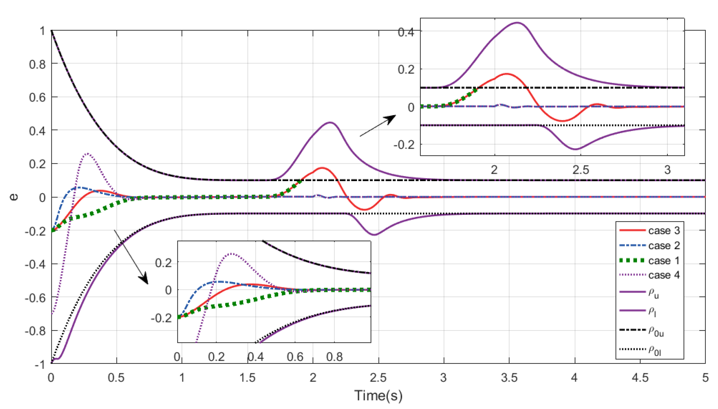
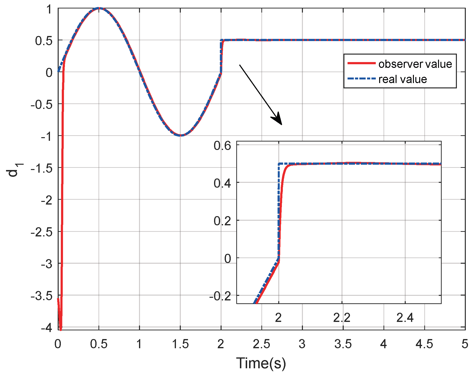
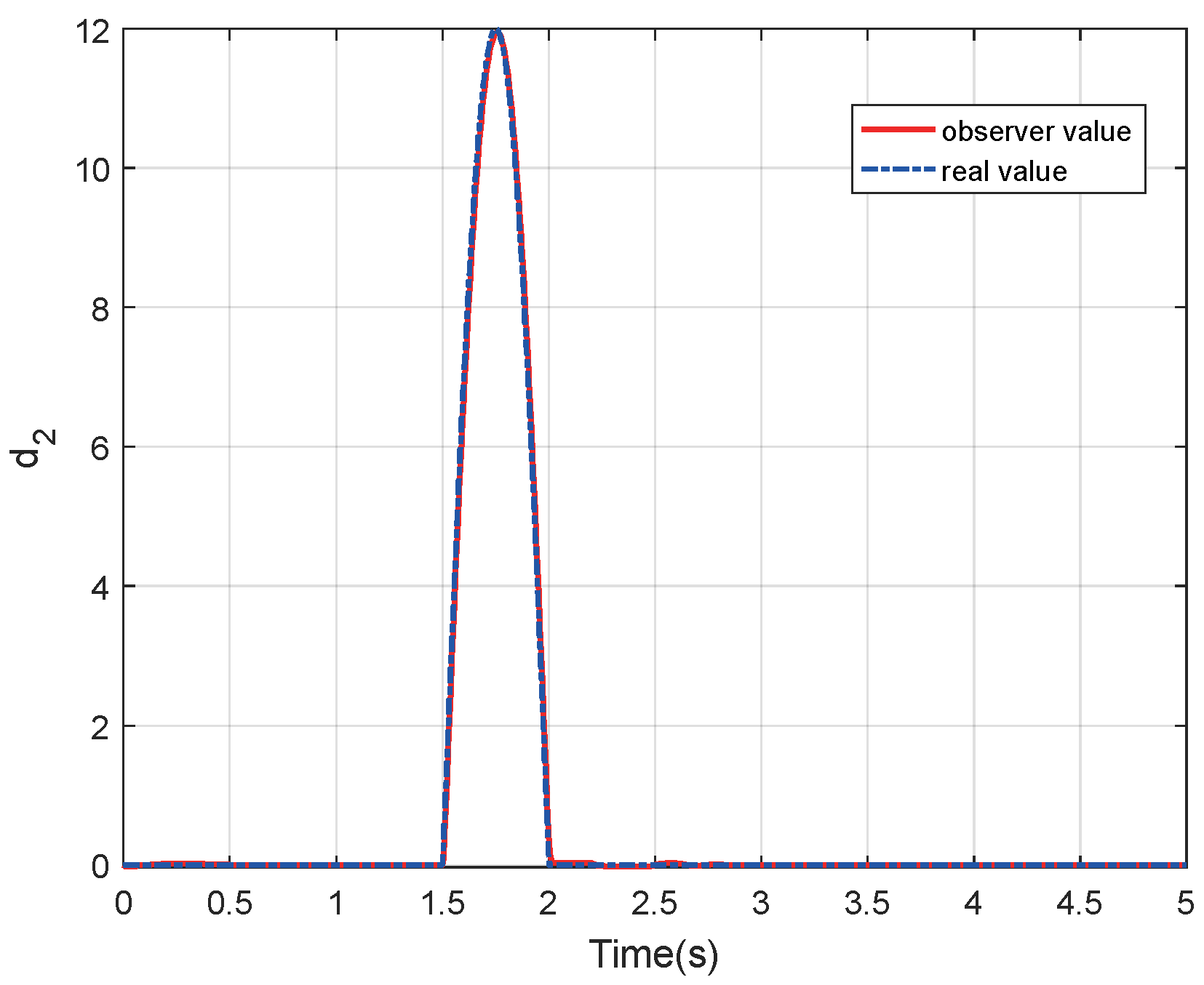
To illustrate the effectiveness of the ASPC, four simulations were conducted in this study. Case 1 is the simulation without the ASPC, and case 2 has no constraints on the control input. Case 3 is the simulation with the ASPC. The controller parameters in case 4 are the same as those in case 2, while the initial states are x 1 0 = 0.5 and x 2 0 = 0 . In practical applications, the chattering phenomenon occurs because the controller obtains sign · . Therefore, we substitute sat · for sign · . According to Figure 2, we observe that the tracking error consistently remains within the performance boundary ρ 0 u , ρ 0 l in cases 2 and 4. The “explosion of complexity” is avoided by introducing a fixed-time filter to obtain indirect differentiation. And the convergence time (within 0.8 s) is a fixed time that is independent of the initial state. Figure 3 and Figure 4 show that the mismatched and matched disturbances are precisely estimated after a fixed time (less than 0.2 s), which verifies Theorem 2. In other words, the DSC in this paper can accomplish the tracking of control commands, even in the presence of mismatched and matched disturbances. Even if the disturbances suddenly increase or decrease, the fixed-time DO is precisely reconstructed within 0.2 s (Figure 3).
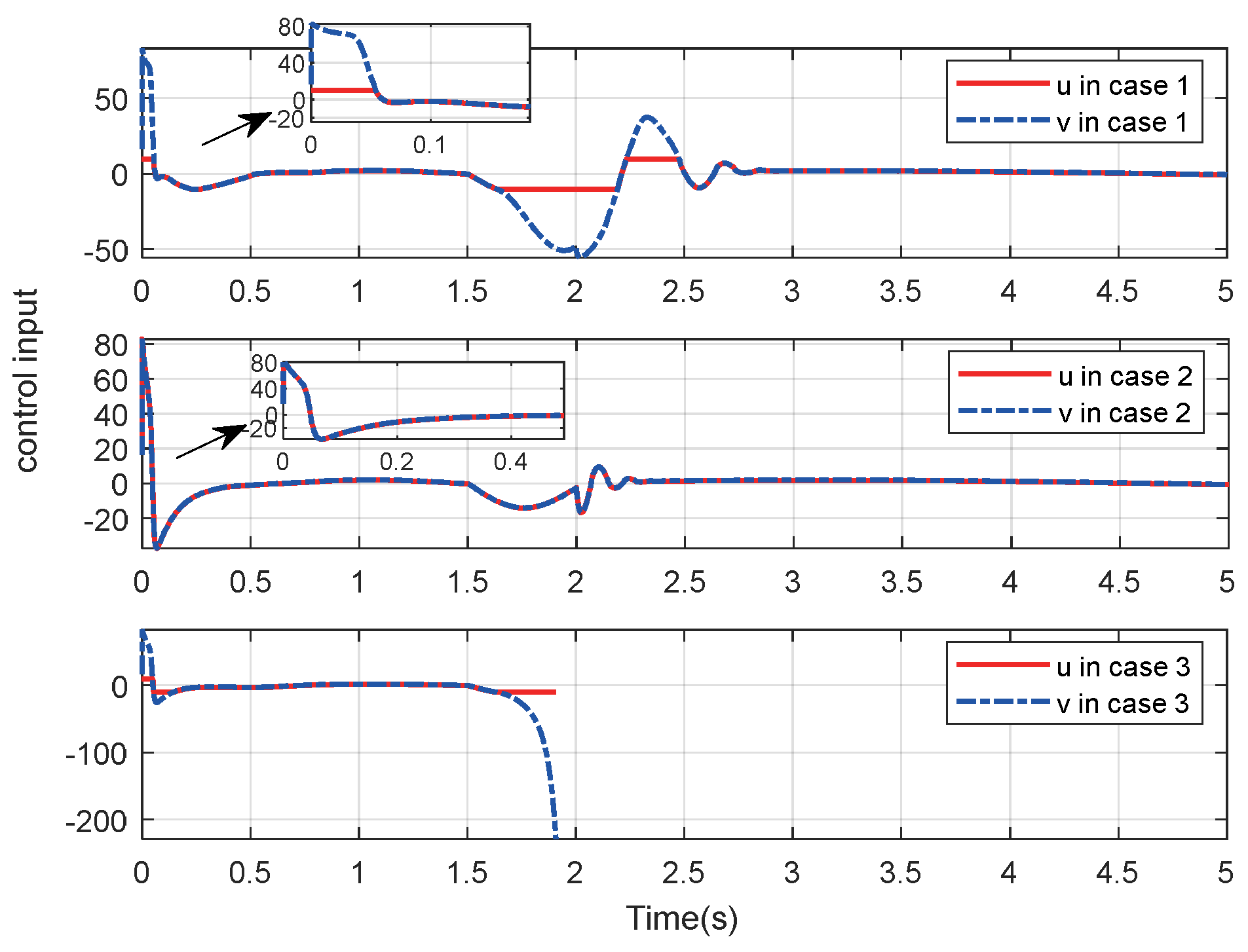
As shown in Figure 2, Figure 5, and Figure 6, tracking error occurs near the boundary of the PPF in case 3 when input saturation occurs. The desired input becomes increasingly large if the value of the tracking error continues to approach the PPF. Additionally, the stability is compromised when the tracking error exceeds the boundary of the PPF. In Figure 2, e in case 1, surpass ρ u when t > 1.91   s . Then, the constraint of inequality (16) is not satisfied. This leads to the failure of the control system, and the desired control effect cannot be achieved. If the PPF is not modified, this phenomenon is inevitable in some situations, such as when large disturbances persist over long periods of time.
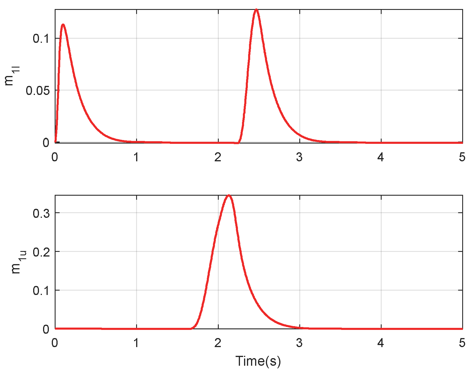
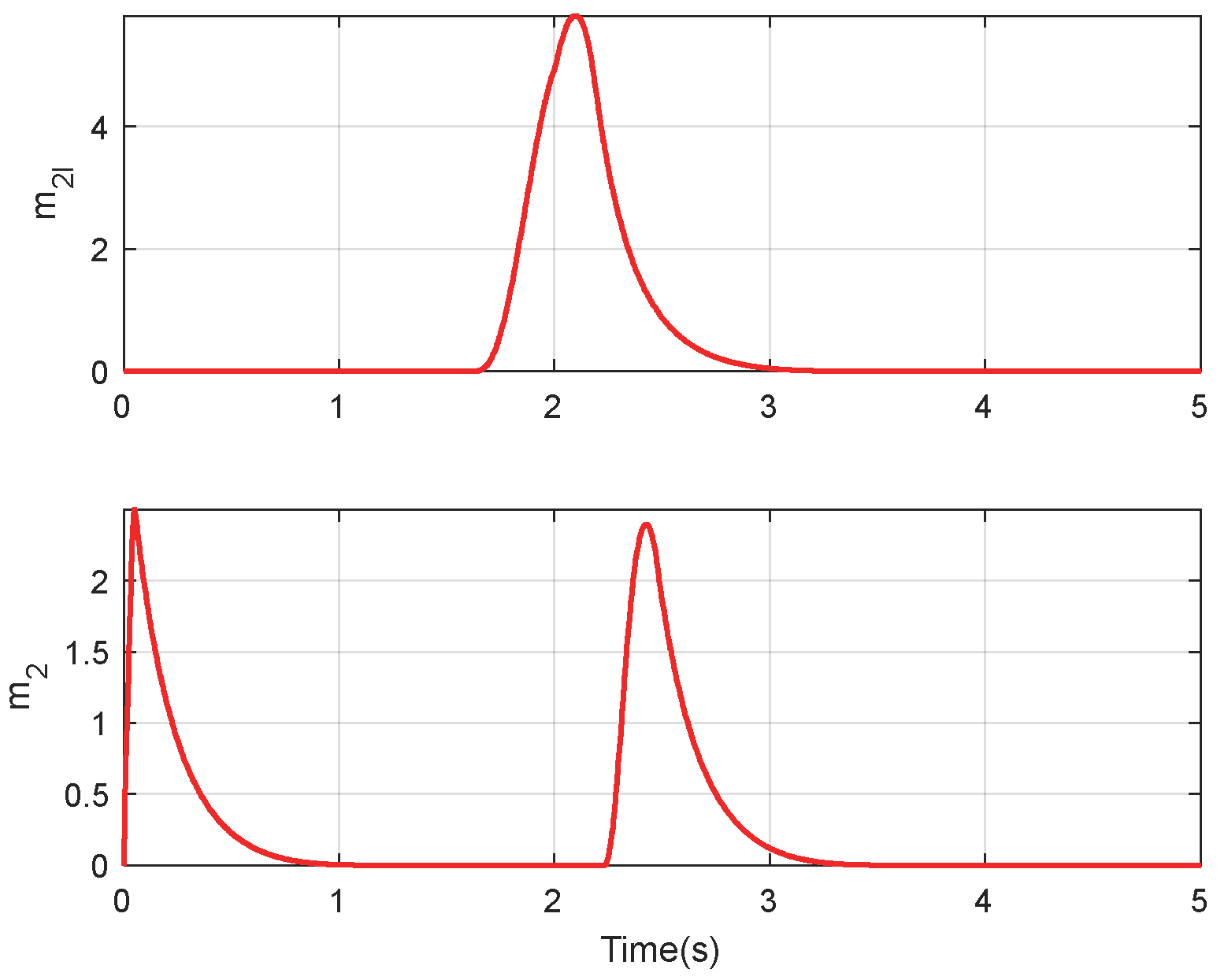
In contrast, the proposed ASPC can modify the boundary of the PPF when input saturation occurs. In Figure 7 and Figure 8, the error between the desired control input and the actual control input determines the value of m 1 l , m 1 u , m 2 l and m 2 u . The boundary of PPF can only be enlarged because all the states are guaranteed to be nonnegative. This means the tracking performance is weakened when v u . After the saturation process ends, the ASPC vanishes within the predefined time of 4 s. The PPF can be restored to the predetermined value within a predetermined interval to avoid the impact on the control performance. Therefore, the double integrator system verifies the effectiveness of the proposed control method.

4.2. Simulation of an RLV Model

The effectiveness of the proposed method, as applied to the RLV model, is verified in this subsection. The parameters of the RLV are shown in Table 2. The control parameter settings are the same as Table 1, except for ρ 0 = 8 deg , ρ = 1 deg . The minimum and maximum values of the control input are v _ = 15 , 10 , 15 T deg and v ¯ = 15 , 10 , 15 T deg , respectively. In addition, a sudden gust occurs in the pitch channel, and the magnitude of its effect is
d w i n d = J y y 15 cos 4 π ( t 5 ) if   5 < t < 5.25 7.5 cos 8 π ( t 5.125 ) 7.5   if   5.125 t < 5.25 0     else
Meanwhile, the actuators experience faults at the time t = 3 . In this simulation, the fault type of actuators is considered as loss of effectiveness, with a failure factor of 0.1667 in the pitch channel. This means the minimum and maximum values of control input change to v _ = 2.5 , 10 , 2.5 T deg and v ¯ = 2.5 , 10 , 2.5 T deg [31]. The parameter uncertainties of the model are selected as a 10% bias for the moment of inertia and a 20% bias for aerodynamic coefficients.
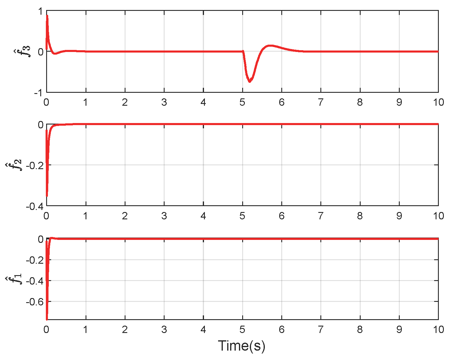
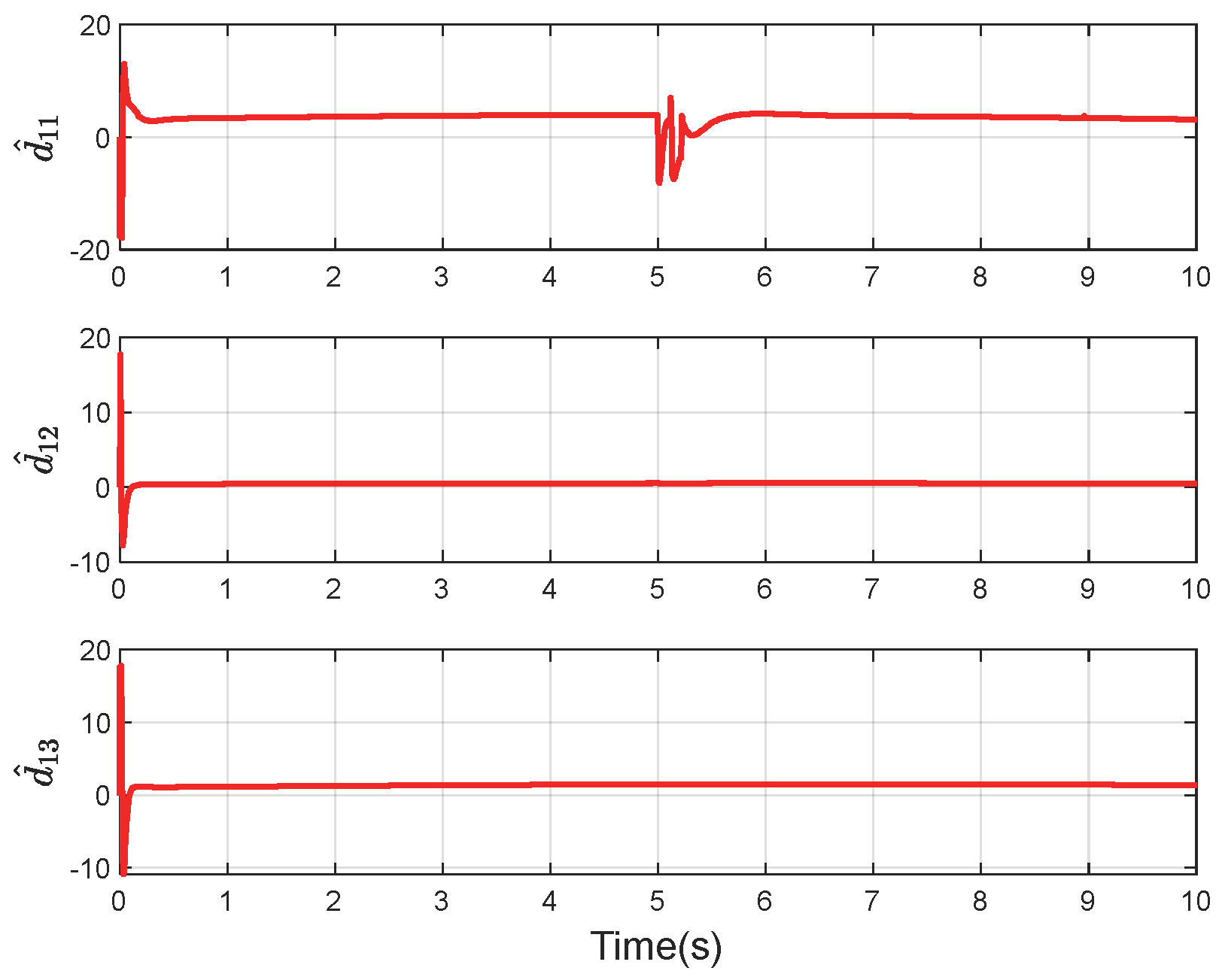
The simulation results in Figure 9, Figure 10, Figure 11, Figure 12 and Figure 13 indicate that the convergence time of the attitude tracking error e 1 in three attitude channels is t T f = 1.5   s , and e 1 is confined within the predefined region 1 , 1 deg . It can be observed that the control input saturation occurs at 5 s when the actuator fails. If the controller does not contain the ASPC, it will lose its function, resulting in the failure of the mission. The PPF with ASPC will recover to the predefined region when the ASPC returns to the origin within a predetermined interval of 4 s.

5. Conclusions

In this paper, the tracking control problem of RLVs is solved on the basis of the ASPC, modified PPF, fixed-time DO, and fixed-time DSC.
(1)
A PPF that is based on an ASPC is derived to ensure stability when saturation occurs. The ASPC can vanish within the predefined time interval after the saturation process ends, which reduces the impact on the PPF. In addition, it can reduce predefined performance when actuator saturation occurs, preventing ambiguity issues.
(2)
A fixed-time DO is introduced to estimate the mismatched and matched disturbances within a fixed-time interval. Its convergence time is independent of the initial error state, which helps in the pre-tuning of the control parameters.
(3)
On the basis of error transformation, a fixed-time DSC is proposed, and the converted system states converge to the residual set of the origin within a fixed time.
This means the attitude tracking error will converge to a predetermined region within a predefined time under the input saturation and mismatched disturbance. As future work, we intend to transplant this control algorithm to an embedded platform.

Author Contributions

D.G.: Conceptualization, Methodology, Writing—Review & Editing, Writing—original draft, Visualization, Validation, Investigation, Formal analysis. M.W.: Formal Analysis, Investigation, Data curation, Supervision. J.C.: Formal Analysis, Investigation, Validation, Visualization, Methodology. Y.Z.: Formal Analysis, Methodology, Writing—Review & Editing, Writing—original draft. N.C.: Conceptualization, Validation, Resources, Supervision. All authors have read and agreed to the published version of the manuscript.

Funding

This paper is supported by grants from the National Natural Science Foundation of China (No. 62373124 and No. U2241215).

Data Availability Statement

The data is unavailable due to privacy or ethical restrictions.

Acknowledgments

The authors are grateful to the School of Astronautics, Harbin Institute of Technology.

Conflicts of Interest

Author Dr. Jie Cheng was employed by the company Shenyang Aircraft Design and Research Institute, Aviation Industry Corporation of China The remaining authors declare that the research was conducted in the absence of any commercial or financial relationships that could be construed as a potential conflict of interest.

References

  1. Chai, R.; Tsourdos, A.; Savvaris, A.; Chai, S.; Xia, Y.; Chen, C.P. Review of advanced guidance and control algorithms for space/aerospace vehicles. Prog. Aerosp. Sci. 2021, 122, 100696. [Google Scholar] [CrossRef]
  2. Tian, B.; Li, Z.; Zhang, X.; Zong, Q. Adaptive prescribed performance attitude control for RLV with mismatched disturbance. Aerosp. Sci. Technol. 2021, 117, 106918. [Google Scholar] [CrossRef]
  3. Kerr, M.; Marcos, A.; Pein, L.; Bornschlegl, E. Gain Scheduled FDI for a Re-Entry Vehicle. In Proceedings of the AIAA Guidance, Navigation and Control Conference and Exhibit, Honolulu, HI, USA, 18–21 August 2008. [Google Scholar]
  4. Cai, G.; Duan, G.; Hu, C. A velocity-based LPV modeling and control framework for an air-breathing hypersonic vehicle. Int. J. Innov. Comput. Inf. Control IJICIC 2011, 75A, 8115–8135. [Google Scholar]
  5. Zhao, S.; Li, X.; Bu, X.W.; Zhang, D. Prescribed Performance Tracking Control for Hypersonic Flight Vehicles with Model Uncertainties. Hindawi Ltd. 2019, 2019, 3505614. [Google Scholar] [CrossRef]
  6. Wang, F.; Hua, C.; Zong, Q. Attitude control of reusable launch vehicle in reentry phase with input constraint via robust adaptive backstepping control. Int. J. Adapt. Control. Signal Process. 2015, 29, 1308–1327. [Google Scholar] [CrossRef]
  7. Bu, X.; He, G.; Wang, K. Tracking control of air-breathing hypersonic vehicles with non-affine dynamics via improved neural back-stepping design. ISA Trans 2018, 75, 88–100. [Google Scholar] [CrossRef] [PubMed]
  8. Shtessel, Y.; Hall, C.; Jackson, M. Reusable Launch Vehicle Control In Multiple Time Scale Sliding Modes. J. Guid. Control. Dyn. 1999, 23, 1013–1020. [Google Scholar] [CrossRef]
  9. Shtessel, Y.B.; Hall, C.E. Multiple time scale sliding mode control of reusable launch vehicles in ascent and descent modes. In Proceedings of the American Control Conference, Arlington, VA, USA, 25–27 June 2001; IEEE: New York, NY, USA. [Google Scholar]
  10. Han, Z.; Zong, Q.; Tian, B.L.; Ji, Y.H. Hypersonic vehicle attitude control using Terminal sliding mode control. Kongzhi Yu Juece/Control. Decis. 2013, 28, 259–263+268. [Google Scholar]
  11. Burken, J.J.; Lu, P.; Wu, Z.; Bahm, C. Two Reconfigurable Flight-Control Design Methods: Robust Servomechanism and Control Allocation. J. Guid. Control. Dyn. 2012, 24, 482–493. [Google Scholar] [CrossRef]
  12. Hanson, J.M. Advanced guidance and control project for reusable launch vehicles. In Proceedings of the AIAA Guidance, Navigation, and Control Conference and Exhibit, Dever, CO, USA, 14–17 August 2000. [Google Scholar]
  13. Bu, X.; Wu, X.; Ma, Z.; Zhang, R. Nonsingular direct neural control of air-breathing hypersonic vehicle via back-stepping. Neurocomputing 2015, 153, 164–173. [Google Scholar] [CrossRef]
  14. Wang, F.; Zou, Q.; Zong, Q.; Hua, C. Adaptive Prescribed Performance Fault Tolerant Control for a Flexible Air-Breathing Hypersonic Vehicle With Uncertainty. IEEE Access 2019, 7, 35018–35033. [Google Scholar] [CrossRef]
  15. Jing, Y.; Liu, Y.; Zhou, S. Prescribed Performance Finite-Time Tracking Control for Uncertain Nonlinear Systems. J. Syst. Sci. Complex. 2019, 32, 803–817. [Google Scholar] [CrossRef]
  16. Bu, X. Guaranteeing prescribed output tracking performance for air-breathing hypersonic vehicles via non-affine back-stepping control design. Nonlinear Dyn. 2017, 91, 525–538. [Google Scholar] [CrossRef]
  17. Su, R.; Zong, Q.; Tian, B.; You, M. Comprehensive design of disturbance observer and non-singular terminal sliding mode control for reusable launch vehicles. IET Control. Theory Appl. 2015, 9, 1821–1830. [Google Scholar] [CrossRef]
  18. Zhang, X.; Chen, K.; Fu, W.; Huang, H. Neural Network-Based Stochastic Adaptive Attitude Control for Generic Hypersonic Vehicles with Full State Constraints. Neurocomputing 2019, 351, 228–239. [Google Scholar] [CrossRef]
  19. Xu, B.; Shou, Y.; Luo, J.; Pu, H.; Shi, Z. Neural Learning Control of Strict-Feedback Systems Using Disturbance Observer. IEEE Trans. Neural Netw. Learn. Syst. 2018, 30, 1296–1307. [Google Scholar] [CrossRef]
  20. Wang, M.; Yang, Y.; Bai, Y. A novel predefined performance barrier function based adaptive sliding mode control method for RLV under mismatched disturbance. Aircr. Eng. Aerosp. Technol. 2024, 96, 501–513. [Google Scholar] [CrossRef]
  21. Wang, M.; Wei, C.; Pu, J.; Cui, N. Predefined-Time Nonsingular Attitude Control for Vertical-Takeoff Horizontal-Landing Reusable Launch Vehicle. Appl. Sci. 2022, 12, 10153. [Google Scholar] [CrossRef]
  22. Ma, H.; Zhou, Q.; Li, H.; Lu, R. Adaptive prescribed performance control of a flexible-joint robotic manipulator with dynamic uncertainties. IEEE Trans. Cybern. 2021, 52, 12905–12915. [Google Scholar]
  23. Wang, Z.; Liang, B.; Sun, Y.; Zhang, T. Adaptive fault-tolerant prescribed-time control for teleoperation systems with position error constraints. IEEE Trans. Ind. Inform. 2019, 16, 4889–4899. [Google Scholar] [CrossRef]
  24. Yuan, X.; Chen, B.; Lin, C. Neural adaptive fixed-time control for nonlinear systems with full-state constraints. IEEE Trans. Cybern. 2021, 53, 3048–3059. [Google Scholar] [CrossRef]
  25. Ju, X.; Wei, C.; Xu, H.; Wang, F. Fractional-order sliding mode control with a predefined-time observer for VTVL reusable launch vehicles under actuator faults and saturation constraints. ISA Trans. 2022, 129, 55–72. [Google Scholar] [CrossRef] [PubMed]
  26. Ye, D.; Zou, A.M.; Sun, Z. Predefined-time predefined-bounded attitude tracking control for rigid spacecraft. IEEE Trans. Aerosp. Electron. Syst. 2021, 58, 464–472. [Google Scholar] [CrossRef]
  27. Liu, K.; Wang, R.; Wang, X.; Wang, X. Anti-saturation adaptive finite-time neural network based fault-tolerant tracking control for a quadrotor UAV with external disturbances. Aerosp. Sci. Technol. 2021, 115, 106790. [Google Scholar] [CrossRef]
  28. Hu, C.; Gao, Z.; Ren, Y.; Liu, Y. A robust adaptive nonlinear fault-tolerant controller via norm estimation for reusable launch vehicles. Acta Astronaut. 2016, 128, 685–695. [Google Scholar] [CrossRef]
  29. Guo, Y.; Guo, J.; Song, S. Backsteping control for attitude tracking of the spacecraft under input saturation. Acta Astronaut. 2017, 138, 318–325. [Google Scholar] [CrossRef]
  30. Zhang, L.; Liu, J.; Cui, N. Backsteping control for a two-link manipulator with appointed-time convergence. ISA Trans. 2022, 128, 208–219. [Google Scholar] [CrossRef]
  31. Zhang, L.; Wei, C.; Wu, R.; Cui, N. Adaptive fault-tolerant control for a VTVL reusable launch vehicle. Acta Astronaut. 2019, 159, 362–370. [Google Scholar] [CrossRef]
Figure 1. The block diagram of the control system.
Applsci 15 12251 g001
Figure 2. Time histories of the tracking error e .
Applsci 15 12251 g002
Figure 3. Time histories of mismatched disturbance d 1 .
Applsci 15 12251 g003
Figure 4. Time histories of matched disturbance d 2 .
Applsci 15 12251 g004
Figure 5. Time histories of x 1 .
Applsci 15 12251 g005
Figure 6. Time histories of control input u and v .
Applsci 15 12251 g006
Figure 7. Time histories of m 1 l and m 1 u .
Applsci 15 12251 g007
Figure 8. Time histories of m 2 l and m 2 u .
Applsci 15 12251 g008
Figure 9. Time histories of σ , β , α .
Applsci 15 12251 g009
Figure 10. Time histories of the attitude tracking error.
Applsci 15 12251 g010
Figure 11. Time histories of f ^ .
Applsci 15 12251 g011
Figure 12. Time histories of d ^ 1 .
Applsci 15 12251 g012
Figure 13. Time histories of u .
Applsci 15 12251 g013
Table 1. Parameter settings in the double integrator system.
Parameters
PPF T f = 1.5 , k = 1.6 , ρ 0 = 1 , ρ = 0.1
ASPC μ = 2 , a m = 0.6 , T m = 2 , p ¯ = 15
Fixed-time DO g 1 = 0.5 , g 2 = 0.5 , λ = 3 , μ = 1.41 , k 1 = 4.4 , k 2 = 27.1
DSC l 1 = 0.8 , l 2 = 2.4 , r 1 = 0.6 , r 2 = 1.2 , τ = 0.1
Table 2. Parameters of RLV [22].
Structural parameters of RLV J x x = 130700   kg m 2 , J y y = 1507000   kg m 2
J z z = 1493000   kg m 2 , J x z = 116000   kg m 2
Reference length L r e f = 36   m
The cross-sectional area S ref = 63   m 2
Mass m = 23155   kg
m x p = 0.16 , m y q = 0.10 , m z r = 0.13
m x β = 0.10 , m y α = 0.27 , m z β = 0.14
m x u 1 = 0.52 , m y u 2 = 2.32 , m z u 3 = 1.22
Initial state variables of RLV height = 30   km , θ = 17.32 , φ = 105.01 σ = 1.0 , β = 1.5 , α = 10.75 p = 0.0   rad / s , q = 0.0   rad / s r = 0.0175   rad / s , v = 2916   m / s
Disclaimer/Publisher’s Note: The statements, opinions and data contained in all publications are solely those of the individual author(s) and contributor(s) and not of MDPI and/or the editor(s). MDPI and/or the editor(s) disclaim responsibility for any injury to people or property resulting from any ideas, methods, instructions or products referred to in the content.