Abstract
To fully exploit the acoustic regulation potential of shell-and-tube heat exchangers, this paper proposes a novel heat exchanger design in which the conventional heat exchange tubes are replaced by triply periodic minimal surface structures. The acoustic transmission characteristics of the TPMS-structured heat exchangers were systematically investigated using the finite element method. Four different types of TPMS heat exchanger models—Gyroid, Schwarz P, Split P, and Schwarz D—were constructed, with a focus on analyzing the influence of key parameters such as unit cell type, unit cell size, and volume fraction on their transmission loss characteristics and acoustic transmission capability. It was found that the effects of these parameters on the acoustic transmission characteristics differ significantly between the 100~1600 Hz and 1700~3000 Hz frequency bands. Based on this, the simulation results of the four TPMS heat exchangers were further compared with experimental data from a shell-and-tube heat exchanger. The results show that in a water medium, the sound insulation performance of the Schwarz P type TPMS heat exchanger is comparable to that of the conventional shell-and-tube heat exchanger below 1600 Hz, whereas it improves significantly above 1600 Hz, with an overall transmission loss of up to 78.49 dB. The findings of this study provide valuable theoretical insights for the development of compact underwater heat exchangers with excellent acoustic performance.
1. Introduction
This study is motivated by the pressing demand for acoustic stealth technology in underwater vehicles, where noise control measures are pivotal for enhancing their acoustic concealment and operational survivability. Research has identified five primary noise sources in underwater piping systems: (1) pump-induced noise; (2) vibration and noise transmitted along pipelines from other equipment; (3) radiated noise generated by heat exchange tube vibrations; (4) flow-induced noise within the piping system; and (5) hydrodynamic noise at hull-side seawater inlets. As an essential component of marine water piping systems, shell-and-tube heat exchangers play a critical role in cooling main engines and mitigating pump-generated noise [1,2,3]. Pipeline noise attenuation strategies primarily involve two methods: installation of dissipative, reactive, or other types of silencers along pipelines [4,5,6,7,8,9,10,11], and optimization of structural parameters in shell-and-tube heat exchangers [12,13,14]. However, conventional noise reduction measures exhibit inherent limitations and practical constraints. For instance, silencer installation is often restricted by confined shipboard spaces, limiting their effective frequency range. Similarly, while increasing pipe diameter may enhance thermal efficiency, it can compromise the noise reduction performance of flexible couplings. To advance the noise suppression capabilities of piping systems, it is imperative to fully exploit the acoustic potential of individual components. The geometric configuration of shell-and-tube heat exchangers, which shares structural similarities with reactive silencers, has recently attracted research attention. For example, You [15] developed a shell-and-tube heat exchange structure incorporating internal annular airbags, while Gong [3] investigated the effects of heat exchange tube length and inlet-insertion pipes on sound transmission loss. These studies demonstrate that internal structural modifications can enhance noise attenuation by reducing upstream noise transmission, confirming the significant untapped acoustic potential of shell-and-tube heat exchangers. Despite these promising findings, parameter optimization approaches for heat exchangers remain insufficiently explored [16], and systematic investigations into the intrinsic acoustic transmission characteristics of shell-and-tube heat exchangers are still lacking [17].
In recent years, driven by the rapid development of additive manufacturing technology [18], triply periodic minimal surface (TPMS) has shown great potential in heat transfer and structural engineering. Owing to their characteristics of three-dimensional spatial periodicity and zero mean curvature at any point, TPMS structures exhibit excellent performance, such as high heat transfer efficiency and high structural strength. They have a compact structure and can derive diverse topological configurations through parameter adjustment, thus possessing great application potential. For details on the generation, development, mathematical expression of the structure, and structural parameters of TPMS, please refer to References [19,20,21]. Essentially, TPMS belongs to metamaterials, but research on TPMS in the acoustic field started relatively late. Existing studies have shown that TPMS structures also have good sound insulation performance [22]. Reference [23] studied Simple Cubic, Body-Centered Cubic, Face-Centered Cubic, and Octet lattices, and the results indicated that these TPMS structures have complete bandgaps, which are closely related to their own material properties and volume fraction. Reference [24] used the finite element method (FEM) to construct a series structure containing seven unit cells for Primitive, IWP, and Neovius types. The results showed that the bandgap width can be adjusted by changing the volume fraction of the structure. Similarly, there are relatively many studies on the acoustic characteristics of TPMS structures that involve modifying the TPMS structure and adjusting geometric parameters [25,26]. P. Tan [27] designed a TPMS sandwich structure with a TPMS structure as the sandwich core layer, which is representative. The analysis parameters included TPMS unit cell type, relative density, perforated plate thickness, unit cell size, and perforation radius. The analysis results showed that under the same thickness, the Primitive type sandwich panel has the optimal sound absorption performance; as the relative density increases, the resonance frequency increases, and the sound absorption coefficient of the structure decreases gradually. Similarly, E. I. Sysoev [28] controlled the average sound absorption coefficient between 0.2 and 0.8 by changing the unit cell size and sample thickness of four configurations—Primitive type, Diamond type, FRD type, and Gyroid type. Existing studies were all carried out under the background of acoustic metamaterials, with the research focus on the acoustic energy loss and bandgap characteristics of TPMS structures between two disconnected regions in the air medium.
This study aims to evaluate the noise reduction potential of triply periodic minimal surface (TPMS) structures when employed as the core heat transfer component in shell-and-tube heat exchangers. As an exceptional class of acoustic metamaterials, TPMS structures demonstrate remarkable sound insulation performance in air and have shown promise for passive noise control applications. However, whether their acoustic characteristics remain effective when integrated into heat exchanger configurations operating in a water medium warrants systematic investigation. T. Silva [29] pointed out that the main challenge in designing TPMS configurations lies in how to correctly select the unit cell type and volume fraction to obtain the performance required for specific applications. The TPMS structures selected in this study are based on prior research findings [30,31,32,33], focusing on types demonstrating superior performance in heat transfer efficiency and pressure drop characteristics. These optimal TPMS configurations are integrated into shell-and-tube heat exchangers (hereinafter referred to as TPMS-structured heat exchangers) through fusion design. Four classic TPMS structures (Gyroid type, Schwarz P type, Split P type, and Schwarz D type) were used as the heat exchange core of the shell-and-tube heat exchanger. The effects of unit cell type, unit cell size, and volume fraction on the sound transmission characteristics of the TPMS-structured heat exchanger in the water medium were systematically analyzed. This study provides a reference for reducing pipeline system noise and developing compact heat exchangers with small volume and excellent sound insulation performance.
2. Structural Design of Shell-And-Tube Heat Exchanger Integrated with TPMS Structures
2.1. Subsection
Mathematically, TPMS structures are represented as surfaces described by implicit function equations. The level set approximation equations for the four structures (Gyroid type, Schwarz P type, Split P type, and Schwarz D type) are shown in Table 1. The geometric diagrams of the unit cells generated based on the level set approximation equations are shown in Figure 1. All TPMS geometric models were generated using nTopology software v5.19.3.

Table 1.
The structural type and level set equations for the five co-continuous cubic network structures.
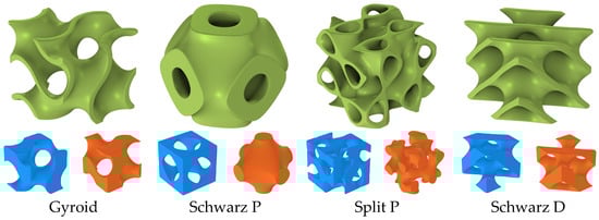
Figure 1.
The two regions partitioned (blue and orange parts) by the skeletal sheet (the olive green parts) in a TPMS 3D model.
2.2. Design of TPMS-Structured Heat Exchanger
The structure of a typical shell-and-tube heat exchanger is shown in Figure 2. The total length of the heat exchanger is 2400 mm; the heads are symmetrically installed on both ends. Each end cover is a combination of a semi-ellipsoidal shell and a cylindrical shell, with an inner diameter of 650 mm and a length of 700 mm (including the inlet/outlet water pipes and flanges). The heat exchange tubes have a length of 1000 mm, an inner diameter of 14 mm, a wall thickness of 1 mm, and a center distance of 22 mm. The total number of heat exchange tubes is 600.
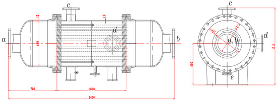
Figure 2.
Structural diagram of a typical shell-and-tube heat exchanger.
The design approach of integrating the TPMS structure with the STHE is to replace the heat exchange core of the STHE with a TPMS skeletal sheet, while keeping other parts unchanged. The TPMS skeletal sheet can divide the space where it is located into two disconnected domains: the high-temperature fluid domain and the low-temperature fluid domain. The design of the TPMS-structured heat exchanger is shown in Figure 3.
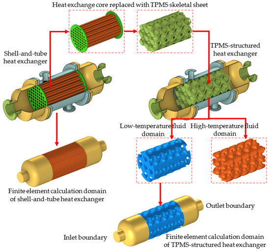
Figure 3.
Design schematic of a TPMS-structured heat exchanger.
As mentioned in the introduction, the typical design parameters of TPMS structures include unit cell type, unit cell size, and volume fraction. In this study, two unit cell sizes were designed, a = 100 mm and a = 200 mm, corresponding to volume fractions RD = 20%, 30%, 40%, and 50%. The effects of three design parameters (unit cell type, unit cell size, and volume fraction) on the sound transmission characteristics of the TPMS-structured heat exchanger were discussed. The formula for calculating the volume fraction is as follows:
In the formula, V0 represents the volume of the TPMS skeletal sheet, and V represents the volume of the space occupied by the TPMS unit cell.
3. Analysis and Discussion
3.1. Analysis Method
In this study, the acoustic problem of boundaries was solved in the COMSOL Multiphysics v6.1 finite element analysis environment. The low-temperature fluid flows into the heat exchanger through the inlet, passes through the low-temperature fluid domain, and flows out through the outlet on the other side of the heat exchanger, forming the finite element calculation domain, as shown in Figure 2. This study focuses on the influence of the TPMS structure on the acoustic transmission characteristics of the TPMS heat exchanger. The rigid acoustic boundary condition can be expressed as
where ρc is the density of the water medium, pt is the total sound pressure, n is the normal vector, and qd is the dipole source (default to 0).
When considering the influence of structure on acoustic transmission characteristics, the fluid is assumed to be stationary, and a plane wave p0 is incident at the inlet boundary of the cold fluid domain of the TPMS structure heat exchanger. A sound-hard boundary condition is applied to all boundaries except the outlet. Under these conditions, the acoustic power at the inlet and outlet boundaries can be expressed by Equations (3) and (4), respectively.
In the formulas, p0 and p represent the sound pressure at the inlet and outlet, respectively; A is the area of the inlet and outlet boundaries affected by the wave; the density of the water medium ρ = 1000 kg/m3; and the speed of sound in water cl =1500 m/s.
The formula for calculating the sound transmission loss is
3.2. Effect of Unit Cell Type on the Transmission Loss Performance of the TPMS-Structured Heat Exchanger
Different unit cell types have different geometric structures and pore characteristics, which affect the acoustic performance of the TPMS-structured heat exchanger. For ease of analysis, the ratio of the volume of the low-temperature fluid domain VL to the volume of the space occupied by the TPMS unit cell V is defined as porosity (P). To investigate the impact of TPMS cell type on the sound insulation performance of the heat exchanger, while maintaining constant parameters of RD = 40% and a = 200 mm, the sound transmission loss characteristics of TPMS-structured heat exchangers were examined using Gyroid, Schwarz P, Split P, and Schwarz D types as the thermal cores, respectively. Additionally, the sound transmission capabilities of these four core types were analyzed.
COMSOL software v6.1 requires the computational domain to be discretized with mesh elements smaller than or equal to 1/6 of the acoustic wavelength. Taking the Gyroid structure with a = 200 mm and RD = 20% as an example, when the maximum element size is set to λ/6, the mesh contains approximately 143,095 domain elements. In contrast, a maximum element size of λ/8 results in about 174,887 domain elements. Comparative analysis reveals negligible differences between the two mesh configurations. The results are presented in Figure 4. Therefore, to conserve computational resources, the maximum element size is set to λ/6 for all simulations.
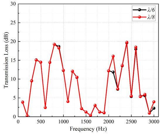
Figure 4.
Results with different mesh sizes.
Figure 5 shows the variation curves of sound transmission loss with frequency for the four types of TPMS-structured heat exchangers. From the figure, it can be observed that the calculation results within the analyzed frequency range can be divided into two parts. In the 100–1600 Hz frequency band, the positions of the peaks and troughs in the sound transmission loss values are essentially consistent, and their magnitudes are similar. This is because, within the 100–1600 Hz range, the sound waves have longer wavelengths, resulting in low sound wave energy loss (as shown in Figure 6a). Additionally, when RD = 40%, the porosities of the four unit cell types are very close (as shown in Figure 6b), indicating that the unit cell type has little influence on the sound insulation capability of the TPMS-structured heat exchangers in this frequency range. However, when the sound wave frequency is in the 1700–3000 Hz range, the difference in sound insulation capability between the Schwarz P type and the other three heat exchangers becomes prominent. This is specifically manifested as differences in curve amplitudes and increased disparities in the positions and magnitudes of peaks and troughs, indicating that the geometric characteristics of the structure gradually enhance the dissipation of sound waves. From the perspective of sound wave transmission capability, the positions of the peaks and troughs of the transmission coefficient in this frequency range are no longer consistent, as shown in Figure 6a. Therefore, its sound insulation capability is relatively outstanding. The reason for this phenomenon lies in the simple structure of the Schwarz P unit cell, where the geometry of its low-temperature fluid domain resembles that of an expansion tube [34], as shown in the orange region separated by the Schwarz P plate-layer in Figure 1. The heat exchange core of the Schwarz P type can be regarded as a series of multi-stage expansion tubes based on its geometric shape. The literature [34] provides the transfer matrix for a single-stage expansion tube as
where L1 represents the length of the expansion tube, S1 denotes the cross-sectional area of the expansion tube, and k indicates the wave number of the medium.
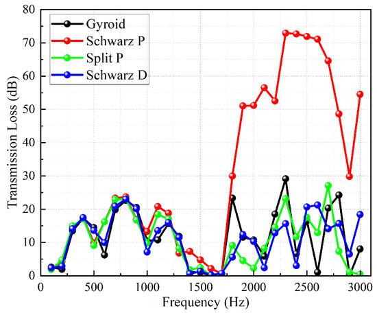
Figure 5.
Curves of transmission loss values of four TPMS-structured heat exchangers with frequency.
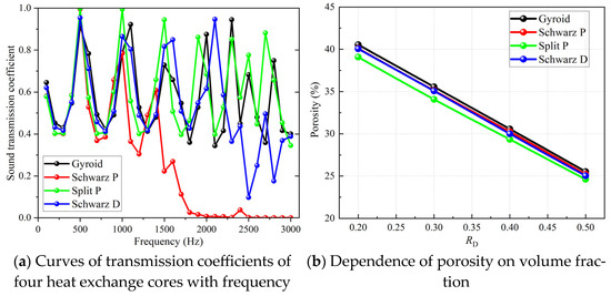
Figure 6.
Transmission coefficient curves of heat exchange cores and the relationship between porosity and volume fraction.
For a two-stage expansion tube in series, the transfer matrix is
where S0 represents the cross-sectional area of the connecting pipe. By extension, the transfer matrix for multiple expansion tubes connected in series is
Denoting the four elements of Ttotal as A, B, C, and D, respectively, the sound transmission loss can be calculated using the formula
where Z0 = clρc/S0.
As can be seen from the transfer matrix, the sound insulation capability and effective frequency range of expansion tubes are related to the cross-sectional areas S0 and S1 of the pipes and the length L1 of the expansion tube. This paper presents both theoretical analytical solutions (AS) and finite element analysis results for the transmission loss curves versus frequency of single-stage to five-stage expansion tubes, as shown in Figure 7. The length of both connecting pipes and expansion tubes is 0.1 m, with radii of 0.02 m and 0.05 m, respectively. Figure 7 shows that the theoretical calculations and finite element simulation results have comparable magnitudes and consistent trends, verifying the accuracy of the computational results. As the number of expansion tubes in series increases, the maximum transmission loss rises from 9 dB for a single stage to 73 dB for five stages. It is precisely the unique geometric configuration of the Schwarz P type heat exchange core that endows it with high-performance sound insulation capability. Clearly, by controlling the volume fraction (RD) of the heat exchange core and its gradient variation (the computational models in this study do not include gradient variation), targeted noise attenuation at specific frequencies can be achieved.
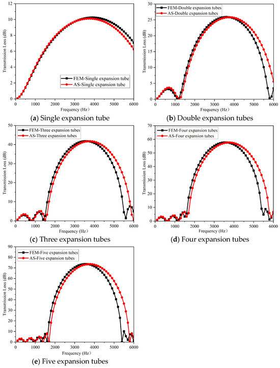
Figure 7.
Sound transmission loss versus frequency for single to five expansion tubes.
3.3. Effect of Unit Cell Size on the Acoustic Transmission Performance of the TPMS-Structured Heat Exchanger
To investigate the influence of the unit cell size a of the four TPMS structures on the sound insulation performance of the TPMS-structured heat exchanger, while maintaining a constant RD = 40%, the finite element method was employed to analyze the effects when the unit cell sizes were a = 200 mm and a = 100 mm. Figure 8a,b show the low-temperature fluid domains for a = 100 mm and a = 200 mm, respectively. It can be observed from the figure that, while keeping the overall geometric dimensions of the thermal core unchanged, an increase in the unit cell size leads to a thickening of the channels in the low-temperature fluid domain. This alteration modifies the sound wave reflection paths and scattering characteristics within the channels, thereby enhancing the structure’s ability to dissipate sound waves at low frequencies.
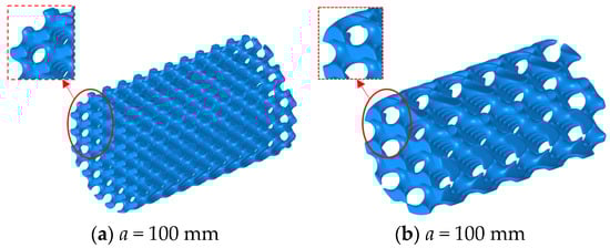
Figure 8.
Geometric changes in the high-temperature fluid domain when the TPMS structure unit cell size changes.
Figure 9, Figure 10, Figure 11 and Figure 12 show the curves of sound transmission loss values and heat exchange core sound transmission coefficients of the four TPMS-structured heat exchangers with frequency when the unit cell sizes are a = 200 mm and a = 100 mm. It can be seen from the transmission loss curves that the effect of unit cell size on the sound insulation performance of the TPMS-structured heat exchanger varies in the two frequency bands 100~1600 Hz and 1700~3000 Hz. In the frequency band of 100~1600 Hz, the transmission loss values differ slightly, and the peaks and valleys are basically at the same positions. Combined with the corresponding heat exchange core transmission coefficient curves, it can be seen that the transmission coefficients in this frequency band are basically similar, indicating that the change in unit cell size has little effect on the transmission loss in the frequency band of 100~1600 Hz, which is related to the long wavelength of the incident acoustic wave.
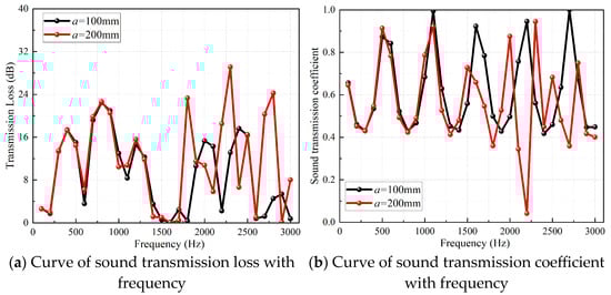
Figure 9.
Curves of transmission loss and heat exchange core transmission coefficient of Gyroid type TPMS-structured heat exchanger with frequency.
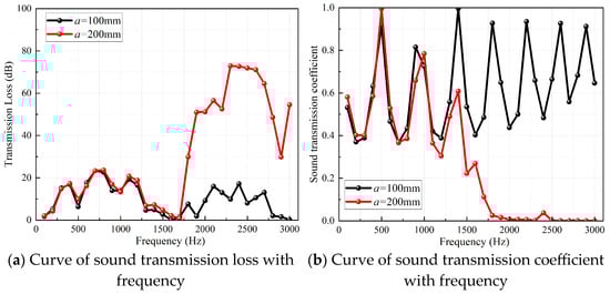
Figure 10.
Curves of transmission loss and heat exchange core transmission coefficient of Schwarz P type TPMS-structured heat exchanger with frequency.
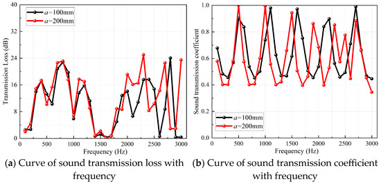
Figure 11.
Curves of transmission loss and heat exchange core transmission coefficient of Split P type TPMS-structured heat exchanger with frequency.
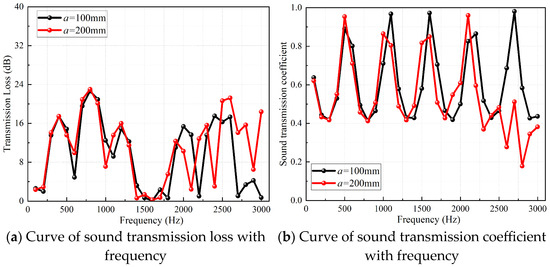
Figure 12.
Curves of transmission loss and heat exchange core transmission coefficient of Schwarz D type TPMS-structured heat exchanger with frequency.
However, in the frequency band of 1700~3000 Hz, the transmission loss values when a = 200 mm are generally higher than those when a = 100 mm, and the peaks tend to shift to low frequencies. From the analysis of the transmission coefficient curves, the peaks of the transmission coefficient when a = 200 mm are generally lower than those when a = 100 mm in this frequency band, and the peaks tend to shift to low frequencies. For example, as shown in Figure 9a, when the unit cell size a = 100 mm, the peaks appear at 2000 Hz, 2400 Hz, and 2900 Hz; when the unit cell size a = 200 mm, the peaks shift to low frequencies of 1800 Hz, 2300 Hz, and 2800 Hz. This is because the porosity when a = 200 mm is larger than that when a = 100 mm, and the channel provides more space for acoustic wave scattering and energy dissipation, increasing the interaction time between acoustic waves and the structure and improving the dissipation efficiency of acoustic energy. In addition, in the frequency band of 1700~3000 Hz, the Schwarz P type has the optimal sound insulation performance, with an overall level of 78.49 dB, followed by the Gyroid type with approximately 31.94 dB, the Split P type with approximately 29.80 dB, and the Schwarz D type with approximately 24.29 dB. This is because the geometric structure of the Schwarz P type is similar to that of a Helmholtz resonator.
3.4. Effect of Volume Fraction on the Transmission Loss Performance of Heat Exchangers
To explore the effect of volume fraction RD on the sound transmission characteristics of the TPMS-structured heat exchanger, a = 200 mm was kept unchanged. Four volume fractions, RD = 20%, RD = 30%, RD = 40%, and RD = 50%, were designed to analyze the effect of volume fraction changes of the four units cell type on the sound transmission characteristics of the TPMS-structured heat exchanger. The calculation results are shown in the figures below.
As can be clearly observed in Figure 13, Figure 14, Figure 15 and Figure 16, with the increase of RD, the volume of the low-temperature fluid domain is gradually compressed, resulting in a corresponding decrease in porosity. This, in turn, triggers a chain reaction: the flow resistance for sound waves within the fluid domain rises. Furthermore, it becomes increasingly difficult for sound waves to penetrate the internal pores, and the structure’s reflection of sound waves is enhanced. Consequently, the transmitted sound energy decreases, resulting in a lower transmission coefficient and improved sound insulation capability.
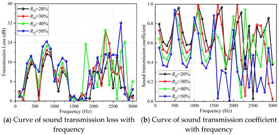
Figure 13.
Curves of transmission loss and heat exchange core transmission coefficient of Gyroid type heat exchanger with RD = 20%, RD = 30%, RD = 40%, and RD = 50%.
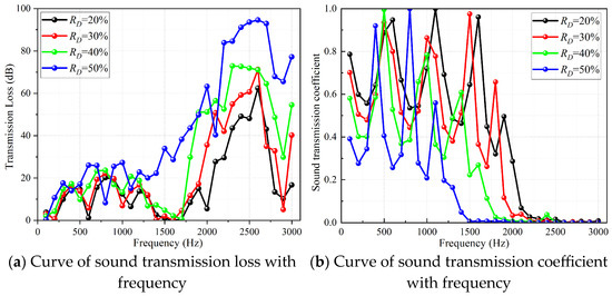
Figure 14.
Curves of transmission loss and heat exchange core transmission coefficient of Schwarz P type heat exchanger with RD = 20%, RD = 30%, RD = 40%, and RD = 50%.
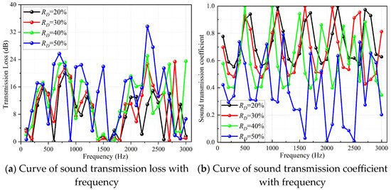
Figure 15.
Curves of transmission loss and heat exchange core transmission coefficient of Split P heat exchanger with RD = 20%, RD = 30%, RD = 40%, and RD = 50%.
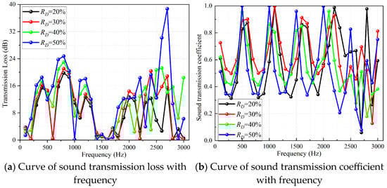
Figure 16.
Curves of transmission loss and heat exchange core transmission coefficient of Schwarz D type heat exchanger with RD = 20%, RD = 30%, RD = 40%, and RD = 50%.
4. Comparison with the Sound Insulation Effect of STHE
To further analyze the sound transmission characteristics of the TPMS structure as the heat exchange core and verify the accuracy of the finite element analysis, the two-source method was used to test the transmission loss value of the STHE, and the test results were compared with the finite element simulation results. The model is shown in Figure 17a, and the main dimensions of the STHE are shown in Figure 2. The test layout of the two-source method [35] is shown in Figure 17b below.
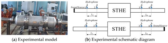
Figure 17.
Experimental model and test layout diagram.
According to the transfer matrix principle, an acoustic component can be described by its transfer matrix quadrupole parameters. The test device was first arranged and measured according to Figure 17b. The quadrupole parameters of measuring points 1–2 and 3–4 can be obtained from the transfer matrix of the straight pipe. Under no-flow conditions,
In the formulas, the subscripts “12” and “34” of the quadrupole parameters correspond to measuring points 1–2 and 3–4, respectively; l12 and l34 correspond to the spacing of measuring points in Figure 17b.
For the section of measuring points 2–3 containing the STHE, its quadrupole parameters can be expressed as
In the formula, the subscript “a” corresponds to the case where the sound source is located on the left side in Figure 17b, and the subscript “b” is used when the sound source is located on the right side.
By integrating the quadrupole parameter expressions of measuring points 1–2, 3–4, and 2–3, the following formula can be obtained:
There are only two equations in the above formula, but four unknowns, A23, B23, C23, and D23. By repositioning the sound source to the right and measuring again, two additional equations can be obtained:
By solving Equations (13) and (14) simultaneously, the quadrupole parameters of measuring points 2–3 can be obtained:
In the formulas, Hji = pj/pi, which is obtained through measurement.
The transmission loss can be expressed as a function of the quadrupole parameters and the inlet/outlet cross-sectional areas:
When the inlet and outlet areas are equal, specifically when Si = SO,
According to the testing principle of the two-source method, two hydrophones (model: BK 8103/10CT) were symmetrically arranged at both ends of the shell-and-tube heat exchanger. The hydrophones have a sensitivity of −211 dB re 1 V/μPa and were installed in straight pipes with an inner diameter of 200 mm. The distance between hydrophones l12 = l34 = 200 mm. Hydrophones 2 and 3 were positioned 360 mm from the inlet and outlet flange faces of the shell-and-tube heat exchanger, respectively. A DN5902 multi-channel data acquisition system was used to collect signals from the four hydrophones (Figure 18). The data acquisition system has an analysis frequency range of 0.1 Hz to 20 kHz, a maximum input voltage of ±10μV, a maximum output current of 5 mA, a frequency resolution of 0.01 Hz, and an amplitude accuracy of 1% (within 2 kHz). During the test, the sampling rate was set to 12.8 kHz. To ensure system stability, three sets of data were collected repeatedly. Although occasional interference from equipment hoisting and crane operation impacts occurred in adjacent areas during testing, the overall acoustic environment remained quiet.
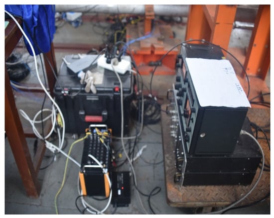
Figure 18.
Signal acquisition equipment.
Before the test, to minimize the experimental interference caused by air inside the pipeline system during the test, all hydrophones were installed on the lower side of the test straight pipe section. The STHE was filled with water and left to stand for a period of time. A vibrator was used as the sound source, and the noise output signal was set to white noise with an effective bandwidth of 10 Hz~2 kHz. The comparison between the analysis results of the measured test data and the simulation calculation results is shown in Figure 19.
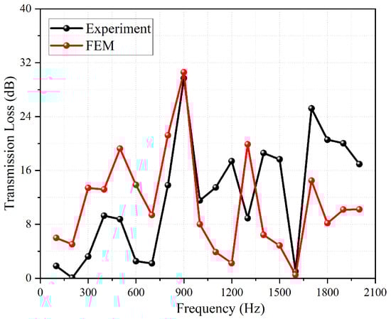
Figure 19.
Comparison between test results and simulation results.
It can be seen from Figure 19 that except for some frequency points, the variation trends of the two curves are consistent. The error in the values is due to the fact that the STHE was placed on the test bench platform during the test, which imposed certain constraints on the STHE, and the excitation of the pipeline by the sound source may have caused resonance of the test bench. The FEM transmission loss values were compared with those of the TPMS-structured heat exchanger with a = 200 mm and RD = 40%, and the results are shown in Figure 20 below.
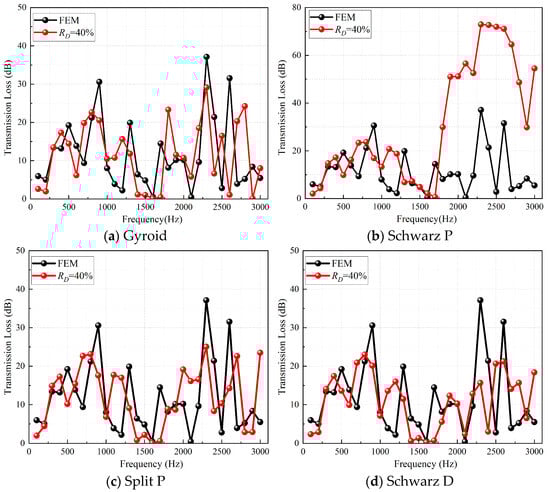
Figure 20.
Curves of transmission loss values of STHE and TPMS-structured heat exchangers with frequency.
From the comparison results shown in Figure 20, it can be seen that in the frequency band of 100~3000 Hz, except for the Schwarz P type, the variation trends of the transmission loss curves of the other three TPMS-structured heat exchangers are basically consistent with that of the STHE, and their values are slightly lower than that of the STHE. However, the transmission loss values of the Schwarz P type heat exchanger in the frequency band of 1700~3000 Hz are much higher than those of the STHE. In terms of the overall level (as shown in Table 2), in the frequency band of 100~3000 Hz, the overall transmission loss levels in descending order are Schwarz P (78.49 dB), FEM (39.22 dB), Gyroid (33.32 dB), Split P (32.21 dB), and Schwarz D (30.44 dB). However, in the frequency band of 100~1600 Hz, the FEM (STHE) has the highest overall transmission loss level, and the Schwarz P type is only 2.54 dB lower than it. In the frequency band of 1700~3000 Hz, the overall transmission loss level of the Schwarz P type is significantly higher than that of other heat exchangers, which also indicates that the Schwarz P type TPMS heat exchanger has excellent sound insulation performance.
Table 2.
Overall level of transmission loss values (dB).
5. Conclusions
This study integrates the TPMS structure with a shell-and-tube heat exchanger for design. The acoustic transmission characteristics of the TPMS-structured heat exchanger are analyzed using finite element methods. The effects of TPMS unit cell type, unit cell size (a), and volume fraction (RD) on the transmission loss characteristics are discussed. The calculation results are compared with experimental data from shell-and-tube heat exchangers, leading to the following main conclusions:
- (1)
- The influence of the TPMS unit cell type on the acoustic transmission characteristics of the TPMS-structured heat exchanger is primarily related to the geometry of the fluid domain isolated by the unit cell type. Among the four types—Gyroid, Split P, Schwarz D, and Schwarz P—the porosity varies only slightly with changes in volume fraction. The fluid domain channels of the first three types are relatively straight, whereas the fluid domain of the Schwarz P type can be regarded as a multi-stage series of expansion tube mufflers along the central axis of the heat exchanger. As a result, its sound insulation performance is particularly outstanding. The frequency range in which its sound insulation performance excels is mainly related to the length and volume of the fluid cavities considered as expansion tubes.
- (2)
- Increasing either the volume fraction or the unit cell size can enhance the sound insulation capability of the TPMS-structured heat exchanger. An increase in volume fraction means that less energy from the sound waves penetrates the heat exchanger core, correspondingly increasing reflection. Increasing the unit cell size, on the other hand, implies an increase in porosity, allowing more sound waves to enter the low-temperature fluid channels. This alters the scattering characteristics and reflection paths of the sound waves, reducing reflected energy and enhancing the geometric structure’s dissipation of sound waves. Therefore, to achieve excellent sound insulation performance, one of these parameters can be increased. In practice, increasing the unit cell size is a more convenient way to achieve good sound insulation performance compared to increasing the volume fraction. For example, for Gyroid type TPMS heat exchangers with a = 100 mm and a = 200 mm, at RD = 30% and 40%, the transmission loss (TL) values are 27.67 dB (100 mm, 30%), 28.95 dB (100 mm, 40%), 32.03 dB (200 mm, 30%), and 33.32 dB (200 mm, 40%), respectively.
- (3)
- The results compared with experimental data from shell-and-tube heat exchangers indicate that, in a water medium, due to the wavelength of sound waves, despite the complex channel variations in the TPMS structure, it remains ineffective at blocking sound wave transmission in the 1700–3000 Hz frequency range, except for the Schwarz P type structure. This study suggests that, to achieve good sound insulation performance underwater, the geometric structure of the TPMS should possess the geometric characteristics of reactive mufflers.
Author Contributions
Conceptualization, R.X. and W.Z.; methodology, J.L.; validation, J.L.; formal analysis, J.L. and T.P.; data curation, J.L.; writing—original draft preparation, J.L.; writing—review and editing, J.L.; project administration, W.Z.; funding acquisition, R.X. All authors have read and agreed to the published version of the manuscript.
Funding
This research was funded by the National Natural Science Foundation of China under grant number 12402318.
Institutional Review Board Statement
Not applicable.
Informed Consent Statement
Not applicable.
Data Availability Statement
The raw data supporting the conclusions of this article will be made available by the authors on request.
Conflicts of Interest
The authors declare no conflict of interest.
Abbreviations
The following abbreviations are used in this manuscript:
| TPMS | Triply Periodic Minimal Surface |
| STHE | Shell-and-Tube Heat Exchangers |
| FEM | Finite Element Method |
| AS | Analytical Solutions |
References
- Liu, X.X. Study on Noise Characteristics of Marine Seawater Piping System. Master’s Thesis, Huazhong University of Science and Technology, Wuhan, China, 2022. [Google Scholar]
- Wu, H. Analytical Calculation and Experimental Study on Acoustic Performance of Water Pipe Silencer. Master’s Thesis, Harbin Engineering University, Harbin, China, 2023. [Google Scholar]
- Gong, J.F.; Jiang, Z.Y.; Yuan, X.J.; Xuan, L.K. Analysis of acoustic attenuation performance of shell and tube heat exchangers. J. Huazhong Univ. Sci. Tech. (Nat. Sci. Ed.) 2020, 48, 55–60. [Google Scholar]
- Zhang, Z.T.; Qin, Z.M.; Bao, C.H.; Hou, L.F.; Sun, K.J.; Long, X.P. Experiment on the noise reduction performance of gas-water cabin in the pipeline system of underwater vehicle. J. Natl. Univ. Def. Technol. 2024, 46, 137–149. [Google Scholar]
- Fu, Q. Study on Sound Insulation Property of Sandwich Composite Aluminum Foam Based on COMSOL. Intern. Combust. Engine Parts 2023, 86–88. [Google Scholar] [CrossRef]
- Karim, S.; Atef, M.; Marwan, H. Experimental Study on Damping Acoustic Pressure Pulsations in Pipeline Systems Using Helmholtz Resonators. J. Press. Vessel Technol. 2019, 142, 021403. [Google Scholar]
- Huang, Y.; Yan, B.; Zhang, H.; Wang, C.; Wang, J.; Zhang, Z.; Huang, Q.; Zhan, X. Transmission Loss Characteristics of Dual Cavity Impedance Composite Mufflers for Non-Planar Wave Cavity Resonance. Appl. Sci. 2024, 14, 6879. [Google Scholar] [CrossRef]
- Hou, J.X.; Zhu, H.C.; Mao, R.F. Theoretical analysis on the transmission loss of a micro-perforated tube muffler with gradually changed back cavity. J. Vib. Shock 2019, 38, 189–194. [Google Scholar]
- Lawrie, J.B.; Guled, I.M. On tuning a reactive silencer by varying the position of an internal membrane. J. Acoust. Soc. Am. 2006, 120, 780–790. [Google Scholar] [CrossRef]
- Hou, J.X.; Zhu, H.C.; Yuan, S.W.; Liao, J.L. Transmission loss of flexible micro-perforated muffler with fexible back cavity for water filled pipelines. Acta Acoust. 2021, 46, 405–414. [Google Scholar]
- Hou, J.X.; Zhu, H.C.; Liao, J.L.; Yuan, S.W. Sound absorption characteristics of underwater flexible micro-perforated sound absorption structure. Acta Acoust. 2021, 46, 135–142. [Google Scholar]
- Li, H.D.; Zhang, Q.Q.; Yang, L.; Akram, N.; Chang, C.L.; Mo, W.L.; Shen, W.F. Detailed design of shell-and-tube heat exchanger using intelligent evolutionary algorithms. CIESC J. 2025, 76, 241–255. [Google Scholar]
- Wang, Y.; Liu, T.; Sha, J.; Ren, H. Large eddy simulation-based analysis of the flow-induced noise characteristics of shell and tube heat exchanger. Int. Commun. Heat Mass Transf. 2023, 148, 107030. [Google Scholar] [CrossRef]
- Elsayed, A.; Bastien, C.; Jones, S.; Christensen, J.; Medina, H.; Kassem, H. Investigation of baffle configuration effect on the performance of exhaust mufflers. Case Stud. Therm. Eng. 2017, 10, 86–94. [Google Scholar] [CrossRef]
- You, C.X.; Pei, Z.X.; He, X.S. Simulation of Acoustic Performance of Submarine Heat Exchanger with Noise Silencing Function. Zaochuan Jishu 2024, 52, 47–54. [Google Scholar]
- Gustafsson, O.; Stignor, C.H.; Dalenbäck, J.O. Heat exchanger design aspects related to noise in heat pump applications. Appl. Therm. Eng. 2016, 93, 742–749. [Google Scholar] [CrossRef]
- Cao, Y.; Ke, H.; Lin, Y.; Zeng, M.; Wang, Q. Investigation on the flow noise propagation mechanism in pipelines of shell-and-tube heat exchangers based on synergy principle of flow and sound fields. Appl. Therm. Eng. 2017, 122, 339–349. [Google Scholar] [CrossRef]
- Niknam, S.A.; Mortazavi, M.; Li, D.S. Additively manufactured heat exchangers: A review on opportunities and challenges. Int. J. Adv. Manuf. Technol. 2021, 112, 601–618. [Google Scholar] [CrossRef]
- Han, L.; Che, S.N. An overview of materials with triply periodic minimal surfaces and related geometry: From biological structures to self-assembled systems. Adv. Mater. 2018, 30, e1705708. [Google Scholar] [CrossRef]
- Izard, A.G.; Bauer, J.; Crook, C.; Turlo, V.; Valdevit, L. Ultrahigh energy absorption multifunctional spinodal nanoarchitectures. Small 2019, 15, e1903834. [Google Scholar] [CrossRef]
- Al-Ketan, O.; Al-Rub, R.K.A. MSLattice: A free software for generating uniform and graded lattices based on triply periodic minimal surfaces. Mater. Des. Process. Commun. 2021, 3, e205. [Google Scholar] [CrossRef]
- Zhuang, X.X.; Xiong, Z.X.; Guo, H.; Sun, Z.Y.; Zhao, L.X. Analysis of the sound insulation performance of triply periodic minimal surface acoustic metamaterials. J. of Appl. Acoust. 2024, 1–9. Available online: https://kns.cnki.net/kcms2/article/abstract?v=0eC8MkjONMG4BZFYtZ6I5b9JdkPyYjJtcVwzYfPuPsDjcsY8TFEi4Q1pzIW-MgbM_JL8pwQTQDeS1EJVfIpHe7ftsRv0p7J6QT-fQyePNXysOpe9o5QSv1OQS5L12XsqmxVoLqJXiY8xInxcNWpyiMDyte4-PLvQWi9aDm5AreRjxgm7smHOlw==&uniplatform=NZKPT&language=CHS (accessed on 7 November 2025).
- Chen, Y.Y.; Wang, L.F. Periodic co-continuous acoustic metamaterials with overlapping locally resonant and bragg band gaps. Appl. Phys. Lett. 2014, 105, 191907. [Google Scholar] [CrossRef]
- Abueidda, D.W.; Jasiuk, I.; Sobh, N.A. Acoustic band gaps and elastic stiffness of PMMA cellular solids based on triply periodic minimal surfaces. Mater. Des. 2018, 145, 20–27. [Google Scholar] [CrossRef]
- Lu, J.-Y.; Silva, T.; Alzaabi, F.; Abu Al-Rub, R.K.; Lee, D.-W. Insights into acoustic properties of seven selected triply periodic minimal surfaces-based structures: A numerical study. J. Low Freq. Noise Vib. Act. Control 2024, 43, 208–219. [Google Scholar] [CrossRef]
- Hur, K.; Hennig, R.G.; Wiesner, U. Exploring Periodic Bicontinuous Cubic Network Structures with Complete Phononic Bandgaps. J. Phys. Chem. C 2017, 121, 22347–22352. [Google Scholar] [CrossRef]
- Tan, P.; Fu, T.; Li, F.C.; Jiang, J.F.; Wang, H. Low-frequency broadband acoustic absorption properties of triply periodic minimal surface acoustic metamaterials. Acta Mater. Compos. Ainica 2024, 42, 2928–2941. [Google Scholar]
- Sysoev, E.I.; Sychov, M.M.; Shafigullin, L.N.; Dyachenko, S.V. Design of Sound Absorbing Honeycomb Materials with a Geometry of Triply Periodic Minimal Surfaces (TPMS). Acoust. Phys. 2024, 70, 887–898. [Google Scholar] [CrossRef]
- Silva, T.; Lu, J.-Y.; Abu Al-Rub, R.K.; Lee, D.-W. Investigation on tailoring the width and central frequency of bandgaps of TPMS structures. Int. J. Mech. Mater. Des. 2024, 20, 317–329. [Google Scholar] [CrossRef]
- Iyer, J.; Moore, T.; Nguyen, D.; Roy, P.; Stolaroff, J. Heat transfer and pressure drop characteristics of heat exchangers based on triply periodic minimal and periodic nodal surfaces. Appl. Therm. Eng. 2022, 209, 118192. [Google Scholar] [CrossRef]
- Cheng, Z.L.; Xu, R.N.; Jiang, P.X. Morphology, flow and heat transfer in triply periodic minimal surface based porous structures. Int. Lournal Heat Mass Transf. 2021, 170, 120902. [Google Scholar] [CrossRef]
- Li, W.H.; Gao, G.Y.P.; Yu, Z.B. Bioinspired heat exchangers based on triply periodic minimal surfaces for supercritical CO2 cycles. Appl. Therm. Eng. 2020, 179, 115686. [Google Scholar] [CrossRef]
- Gajetti, E.; Boccardo, G.; Savoldi, L.; Marocco, L. Hydrodynamic characterization of Gyroid, Diamond and Split-P Triply Periodic Minimal Surfaces as porous medium. Int. J. Heat Mass Transf. 2025, 252, 127439. [Google Scholar] [CrossRef]
- Feng, X.D.T.; Li, X.D.; Liu, K. Computation of total transfer matrix in serial-connection expansion tubes. Tech. Acoiustics 2009, 28, 231–232. [Google Scholar]
- Liu, G.M.; Wang, X.; Zhao, X.C.; Kong, D.Y. Research on Transmission Loss Measurement of Water Mufflers Based on a Thick-Walled Pipe Test Bench. In Proceedings of the 16th Academic Conference on Ship Underwater Noise, Guiyang, China, 22 August 2017. [Google Scholar]
Disclaimer/Publisher’s Note: The statements, opinions and data contained in all publications are solely those of the individual author(s) and contributor(s) and not of MDPI and/or the editor(s). MDPI and/or the editor(s) disclaim responsibility for any injury to people or property resulting from any ideas, methods, instructions or products referred to in the content. |
© 2025 by the authors. Licensee MDPI, Basel, Switzerland. This article is an open access article distributed under the terms and conditions of the Creative Commons Attribution (CC BY) license (https://creativecommons.org/licenses/by/4.0/).