Featured Application
This study proposes a PSS-SMA self-centering joint for seismic-resilient steel frames. The joint achieves nearly zero residual drift and stable energy dissipation, enabling rapid post-earthquake recovery. The findings provide practical guidance for designing next-generation earthquake-resistant steel connections.
Abstract
Self-centering structures have emerged as a promising seismic design solution, offering advantages in structural safety, rapid post-earthquake functionality recovery, and life-cycle economy. This paper introduces a self-centering beam–column joint that integrates superelastic shape memory alloys (SMAs) and prestressed steel tendons as restoring components. A numerical model was developed in OpenSees and validated against experimental results, with discrepancies in residual deformation within 10%. The validated model was used for parametric studies on strand area, prestress, and SMA configuration. The results show that the proposed joint sustains a maximum drift of 6% while maintaining nearly zero residual drift (less than 0.2%), and its hysteresis curve exhibits a stable flag-shaped pattern. The equivalent viscous damping ratio exceeds 0.1, confirming excellent deformation and energy dissipation capacities. These findings highlight the joint’s potential for application in seismic-resilient steel frames.
1. Introduction
Earthquake-resilient design has become an important topic in civil engineering as frequent seismic events continue to cause severe structural damage and economic loss worldwide [1,2,3]. Conventional rigid steel beam–column connections, once regarded as efficient for resisting lateral loads, have shown critical shortcomings in past earthquakes, such as brittle fractures and large residual drifts, which result in costly repairs or even irreparable damage [4,5,6]. These limitations have motivated the development of self-centering systems, which can restore structural configurations after earthquakes and minimize residual deformation [7,8]. Self-centering structures offer not only enhance seismic safety but also rapid post-earthquake recovery and an improved life-cycle economy [9,10].
A wide range of self-centering solutions have been proposed. Post-tensioned connections using steel strands or tendons can provide restoring force [11,12,13], while frictional and energy-dissipating devices improve damping capacity [14,15]. However, balancing reliable recentering capacity with enough energy dissipation remains a persistent challenge. Excessive reliance on plastic energy dissipation may compromise recentering, whereas purely elastic systems often lack enough damping [16,17]. This divergence highlights the need for hybrid solutions that can achieve both stable hysteretic behavior and low residual drift [18,19].
Shape memory alloys (SMAs) have emerged as promising materials in this regard. Due to their superelastic properties, SMAs can sustain large reversible strains of up to 6–8% while providing significant restoring forces [20,21]. Numerous experimental and numerical studies have confirmed that SMA-based connections, including SMA bolts, plates, and tendons, exhibit flag-shaped hysteresis and minimal residual drift [22,23,24]. Despite these advantages, challenges remain in terms of cost, durability, and integration with conventional steel elements. Recent reviews emphasize that SMAs should be combined with traditional structural components to achieve both economic efficiency and seismic resilience [25].
Our earlier work introduced a novel prestressed steel strand–SMA (PSS-SMA) self-centering joint, validated through full-scale experiments and detailed ABAQUS simulations [24]. That study confirmed the mechanical feasibility of combining SMA bars with prestressed steel strands. However, it mainly focused on experimental performance and finite element accuracy. Building upon this foundation, the present study shifts the emphasis toward numerical modeling and parametric design. A simplified yet robust OpenSees model is established and calibrated against experimental data. Using this model, systematic parametric analyses were conducted to evaluate the effects of SMA area, steel strand area, and prestressing levels on joint performance.
The results demonstrate that the proposed joint can sustain a maximum interstory drift angle of 6% while maintaining nearly zero residual drift [26]. These findings provide practical design insights for engineers and contribute to the development of seismic-resilient steel frames with reliable recentering capacity.
2. Materials and Methods
2.1. Joint Configuration
The proposed self-centering beam–column joint integrates SMA bars and PSS to provide restoring force and initial stiffness, respectively. The schematic configuration is shown in Figure 1. Prestressed steel strands mainly control the opening moment of the joint, while SMA bars contribute additional restoring capacity through their superelastic behavior. Friction plates and high-strength bolts are also included to provide supplemental energy dissipation [27,28].
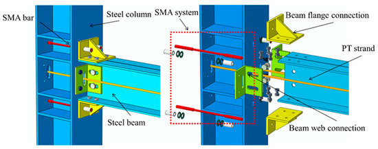
Figure 1.
Joint detail.
2.2. Mechanical Characteristics
The joint behavior can be divided into two stages. Prior to opening, the joint behaves similarly to a conventional rigid connection, and its stiffness can be calculated using classical mechanics [29]. Once opening occurs, the restoring force is governed by the combined effect of prestressed SMA bars, prestressed strands, and the frictional mechanism. The opening moment can be expressed as
In the formula, FSMA is the SMA bar pretension. Fst is pretension of the steel strands, and lSMA and lst represent the distances from the rotation center to the SMA bar and steel strands, respectively. Mf is the flange friction moment [30,31]. Its calculation formula is
In the formula, μ is the friction coefficient of the friction dissipation device. P is the pressure per unit area of the friction surface. Nb is the pretension force of a single high-strength bolt. nb is the number of high-strength bolts, and S is the effective friction surface area.
In hysteresis performance evaluation, secant stiffness is commonly used to represent the overall load-carrying capacity of a structure at a given displacement [32]. It is defined as the slope of the line connecting the origin and a specific point on the load–displacement curve:
where F is the corresponding load and Δ is the displacement. Secant stiffness reflects the effective stiffness of the structure at different deformation levels and serves as a key indicator for stiffness degradation.
On the other hand, energy dissipation capacity is typically quantified by the area enclosed within a hysteresis loop [33]. The energy dissipated in a single loading cycle can be expressed as
where the integration path follows the closed loop of the hysteresis curve. A larger area indicates stronger hysteretic energy dissipation. To enable comparison under different loading conditions, the equivalent viscous damping ratio ξeq is introduced as
where E is the hysteretic energy dissipated per cycle and Es is the corresponding elastic strain energy. This parameter quantitatively reflects the energy dissipation capability of the structure.
2.3. Experimental Study
To validate the accuracy of the finite element (FE) modeling strategy, a supplementary full-scale experiment was conducted on a beam–column joint specimen. The test setup is illustrated in Figure 2. In this program, low-cycle reversed loading was applied at the column end, while the beam end was restrained, to reproduce the seismic demand on the joint region [34]. The specimen was fabricated with material properties and geometric dimensions consistent with those adopted in the FE model, ensuring the comparability between experimental and numerical responses. Two types of joints were investigated: a PSS-SMA joint equipped with both SMA bars and prestressed steel strands, and an SMA joint equipped with SMA bars only. The SMA material had an atomic composition of Ti–50.8 at.% Ni–49.2 at.%, and the austenite finish temperature of the as-hot-rolled bars was approximately 0 °C, indicating that the material remained in the austenitic phase at room temperature.
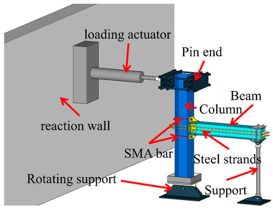
Figure 2.
Schematic diagram of the test setup.
The dimensions of the key components in the test are shown in Figure 3.
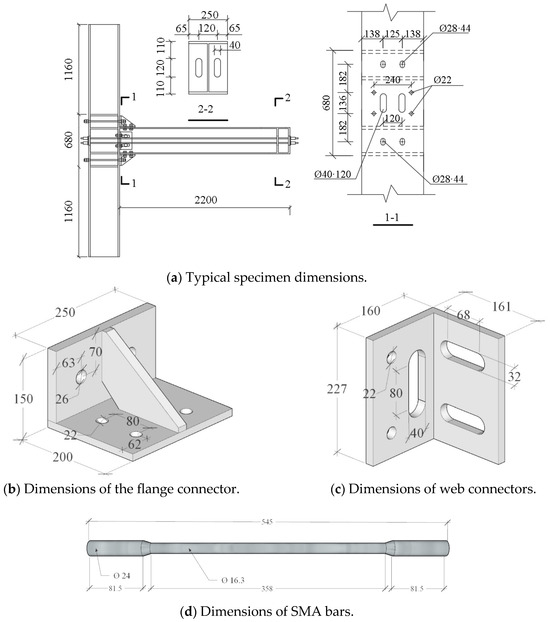
Figure 3.
Geometry of the specimen.
A quasi-static cyclic loading protocol in accordance with the American SAC guidelines [35] was employed, as shown in Figure 4. The column end was subjected to incrementally increasing displacement cycles until significant stiffness and strength degradation occurred or the prescribed maximum deformation was reached. Key response parameters, including applied load, column-end displacement, and joint rotation, were recorded using load cells and displacement transducers. These measurements provided benchmark hysteretic curves and stiffness degradation patterns against which the FE model predictions were evaluated.
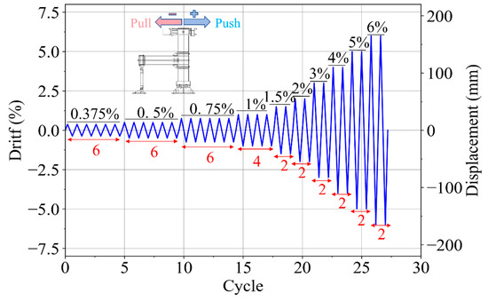
Figure 4.
Loading protocol.
2.4. Finite Element Modeling
Because the jointed subassembly is structurally complex, contains numerous components, and exhibits pronounced nonlinearities, a fully detailed finite element (FE) model would result in a very large number of degrees of freedom, long run times, and potential issues with convergence and numerical stability [36]. To improve computational efficiency and focus on the key mechanical mechanisms, a simplified FE model is adopted. By replacing noncritical subassemblies with constraint idealizations, omitting secondary members, and simplifying contact relationships or material laws, the model reduces the computational demand while preserving the dominant load-transfer paths and analysis accuracy needed for design and parametric studies [37,38]. This strategy enables rapid iteration and optimization for complex systems.
A numerical model of the PSS-SMA joint was developed in OpenSees, and the simplification scheme is illustrated in Figure 5. Nodes 1–9 are the model nodes; Nodes 1 and 8 represent the column inflection points of the adjacent stories. The translational degrees of freedom of Node 8 are fixed, and Node 9 is constrained in the vertical direction. A low-cycle reversed horizontal load (or displacement) is applied at Node 1 to reproduce the seismic demand on the joint.
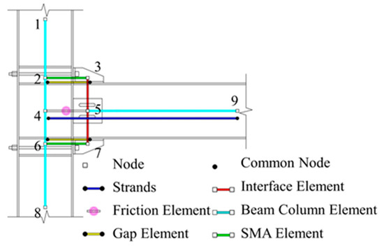
Figure 5.
Detail of model.
The element between Nodes 1 and 8 models the steel column, and the element between Nodes 5 and 9 models the steel beam. Both members are represented by force-based fiber beam–column elements, with the cross-sections discretized into flange and web fibers. The elements spanning Nodes 3–5–7 represent the beam–column interface. Since this interface is assumed to behave kinematically rigid during the opening/closing of the joint, it is modeled using elastic beam–column elements with a very large stiffness (rigid link/rigid arm idealization) [39].
To capture the unilateral opening/closing of the interface, two-node link elements are arranged in parallel between the pairs Nodes 2 and 3 and Nodes 6 and 7. The modeling target is the following: under tension, the gap opens and the axial force is carried exclusively by the SMA branch; under compression, the interface does not open and the compressive force is resisted by a separate branch. Accordingly, two complementary link elements are assigned to each pair to enforce tension-only vs. compression-only behavior and achieve the desired unilateral response.
In addition, a two-node link element between Nodes 4 and 9 represents the prestressed steel strand, and another two-node link element between Nodes 4 and 5 represents the frictional energy-dissipation device. Prestress is introduced via initial strain/force in the strand model, while the friction unit is characterized by a slip (breakaway) force and a sliding law that can include cyclic degradation. Together, these settings form the parallel system of the SMA branch, the steel-strand branch, and the friction branch, which reproduces the joint’s self-centering and hysteretic energy-dissipation characteristics.
2.5. Constitutive Models and Material Parameters
The most important constitutive law in the model is the self-centering material used to represent the SMA bars. This model can reproduce the flag-shaped hysteresis typical of superelastic SMAs. The stress–strain response is shown in Figure 6 [40].
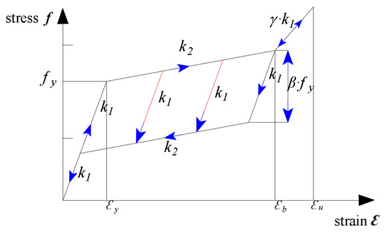
Figure 6.
Self-centering material model for SMA—stress–strain response.
The strain response consists of three stages—elastic, phase transformation, and hardening. Superelasticity is captured by defining the first stiffness (elastic slope), the second stiffness (transformation/unloading slope), the forward transformation stress fy, and the reverse transformation stress coefficient β. The hardening limit strain εb is introduced to simulate the post-transformation hardening process, while the superelastic limit strain εu controls residual deformation; in design, the SMA should be kept within the superelastic regime (ε ≤ εu).
Elastic stage: When f < fy (forward transformation stress), both loading and unloading follow the elastic modulus (first stiffness).
Transformation stage: Once f exceeds fy within the specified transformation strain interval, the loading branch follows the prescribed slope (second stiffness k2), while unloading initially follows the second stiffness down to the reverse transformation stress βfy and then transitions to the second stiffness. When the unloading branch intersects the elastic loading line, the path returns to the elastic unloading curve.
Hardening stage: When ε > εb, the tangent modulus becomes γk1 (where γ is the hardening stiffness ratio; 0 < γ < 1). If unloading proceeds to strains below εb, the material properties revert to those of the previous cycle. When ε further increases beyond εu, the plastic set (residual strain) accumulates and superelastic recovery becomes incomplete. Therefore, in this study the SMA is designed to remain within the superelastic limit (ε ≤ εu) to suppress residual deformation.
The self-centering model contains seven parameters. Based on SMA material tests, the model was calibrated and the parameter values are summarized in Table 1.

Table 1.
Parameter values of SMA material model.
Based on the experimentally obtained mechanical properties of the SMA material, a comparison was conducted with the material properties defined in the model parameters. The results, as shown in Figure 7, indicate that the self-centering model can effectively reproduce the stress–strain response of SMA material. The simulation results capture the stiffness, phase transformation stress, and energy dissipation capacity across different stages, reflecting the actual behavior of SMA material. Moreover, the model is able to accurately simulate both the loading response and deformation characteristics of the material.
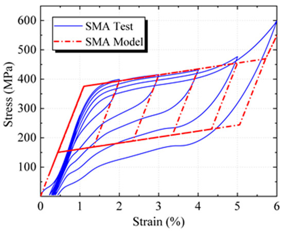
Figure 7.
Comparison of SMA material properties.
The steel strands were modeled using the Steel01 model, which captures nonlinear behavior and stiffness degradation after yielding, as shown in Figure 8a. Material properties were based on testing results. The ultimate tensile strength of the steel strands was defined as 1860 MPa. In the numerical simulation, the steel strands were assumed to fail once their stress exceeded this limit. The Q355B structural steel used in the joint was simulated with the Steel02 model [41], which is based on the Giuffré–Menegotto–Pinto constitutive formulation. This model accounts for kinematic hardening and the Bauschinger effect, allowing accurate representation of the nonlinear behavior of steel under cyclic loading and unloading, as illustrated in Figure 8b.
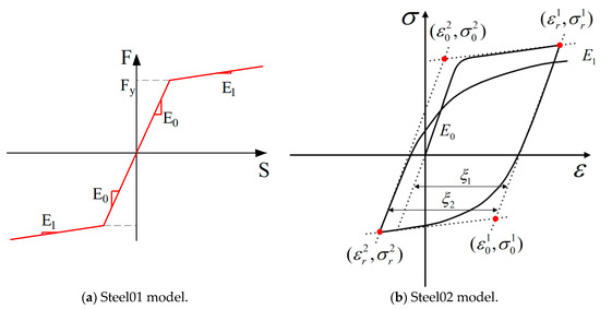
Figure 8.
Steel models. (a) Steel01 model: Bilinear idealized elastic–plastic steel model; (b) Steel02 model: Giuffré–Menegotto–Pinto steel model with cyclic behavior.
The Steel02 model is expressed as Equations (7)–(10).
where σ* and ε* are the normalized stress and strain, respectively. b is the ratio of the linear hardening modulus of steel, E1, to the elastic modulus E0. R controls the shape of the transition curve and reflects the Bauschinger effect. R0 is the initial value during loading. a1 and a2 are two model parameters, and ξ represents the strain difference during the loading process. The parameter values of the Steel02 model are shown in Table 2.

Table 2.
Parameter values of Steel 02 material model.
The opening elements between Nodes 2 and 3 and 6 and 7 were modeled in OpenSees using the ENT (Elastic No Tension) material, whose fundamental properties are shown in Figure 9. These elements were simulated with TwoNodeLink elements [42]. In the analysis, when the interface was subjected to compression, the elements provided stiffness, thereby representing the closed state of the beam–column interface where the SMA bars could not be compressed. Conversely, under tension, the elements did not contribute stiffness, reflecting the open state of the beam–column interface where the SMA bars were stretched.
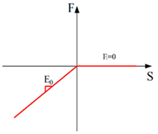
Figure 9.
ENT material properties.
3. Results
3.1. Experimental and Numerical Results
The assembly and testing procedure of the joint are illustrated in Figure 10a. Owing to the pretension applied to the SMA bars and prestress in the steel strands, the joint remained closed until the applied load reached the critical opening moment, as depicted in Figure 10b. At a loading displacement of approximately 0.01 rad, separation initiated between the tension flange of the beam and the adjacent column flange at the connector location. With increasing displacement amplitude, this separation gradually developed into a clear V-shaped gap, as shown in Figure 10c. During the loading process, the pair of shear bolts in the web connector underwent relative sliding, which facilitated efficient shear transfer while permitting the rotational compatibility of the beam. Even under cyclic loading corresponding to a 6% story drift angle, the joint sustained minimal damage, highlighting its remarkable self-centering capacity and ductile behavior.
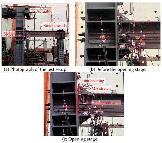
Figure 10.
Test process.
The hysteretic responses of the numerical model and the experimental specimens were compared, as shown in Figure 11. The key results of the joint tests are summarized in Table 3. As shown in the table, the PSS-SMA joint, which incorporated prestressed steel strands in addition to SMA bars, exhibited significantly higher yield and ultimate loads compared with the joint using SMA bars alone. Moreover, the PSS-SMA joint showed a marked reduction in residual deformation, indicating its considerable potential for practical application.
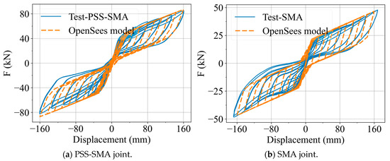
Figure 11.
Hysteresis curve comparison.

Table 3.
Test results.
The finite element (FE) model successfully reproduced the experimental hysteretic behavior with high accuracy, capturing the mechanical response of the joint throughout the entire loading process. Excellent agreement was observed in terms of initial stiffness, yield strength, secondary stiffness, ultimate strength, and unloading stiffness. In the SMA model, the prestressed steel strand elements were omitted to simulate a pure SMA joint.
Noticeable discrepancies were observed during the unloading stage, which can be attributed to differences between the constitutive model of SMA implemented in OpenSees and the actual material behavior. This also led to a certain deviation in the simulated residual deformation. Nevertheless, the predicted yield and ultimate loads of the joint differed from the experimental values by less than 6%. These results confirm that the proposed model is reliable and suitable for further analyses.
3.2. Parameter Analysis
Based on the baseline joint model, a parametric analysis was conducted to investigate the effects on structural stiffness, load-bearing capacity, residual interstory drift angle, and energy dissipation capacity under lateral loading. The corresponding design parameters were identified as the cross-sectional area of the prestressed steel strands (Apss), the prestressing force of the steel strands (Ppss), the cross-sectional area of the SMA bars (ASMA), and the prestressing force of the SMA bars (PSMA).
3.3. Influence of Prestressed Steel Strand Area
According to the nominal cross-sectional areas of prestressed steel strands commonly used in Chinese design codes [43], the initial joint was reinforced with four strands, each with an area of 141 mm2, giving a total area of 564 mm2. To further investigate the influence of strand area on the mechanical performance of the joint, while keeping the initial stress of the strands constant, five alternative strand layouts were developed based on typical strand sizes specified in the code. These layouts consisted of four strands with cross-sectional areas of 54.8, 98.7, 141, and 191 mm2, respectively, as well as a scheme using two strands of 54.8 mm2. The hysteretic curve of the calculated results is shown in Figure 12a.
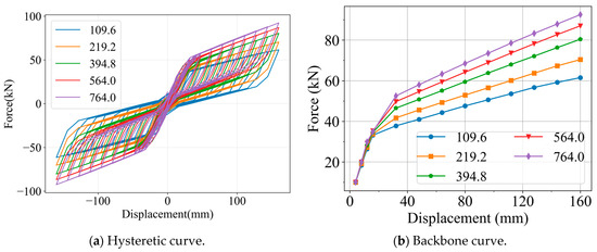
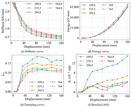
Figure 12.
Influence of Apss.
As shown in the backbone curves in Figure 12b, the load-bearing capacity is positively correlated with the steel strand area, indicating that increasing the strand area enhances both the yield and ultimate loads of the joint. From the stiffness curves in Figure 12c, it can be observed that the strand area has little influence on stiffness before yielding; however, once yielding occurs, joints with larger strand areas exhibit greater stiffness.
In terms of energy dissipation, the results are shown in Figure 12d,e. Joints with smaller strand areas demonstrate higher equivalent viscous damping and greater energy dissipation capacity. This is because when the strand area is small, joint rotation imposes higher loads on the SMA bars, causing them to undergo larger deformations. Under these higher loads, the SMA may even experience plastic deformation beyond the superelastic range, thereby increasing damping and energy dissipation.
Regarding residual deformation, the corresponding results are shown in Figure 12f. Joints with smaller strand areas exhibit larger residual drifts, whereas residual deformation decreases progressively as the strand area increases. Nevertheless, this reduction shows a diminishing marginal effect.
3.4. Influence of Prestressing Force of Steel Strands
The prestressing level of the steel strands in the baseline joint was set to 700 MPa. To further investigate the influence of strand prestressing on the joint performance, the prestressing force was varied to 400, 1000, 1300, and 1600 MPa. The corresponding analytical results are presented in Figure 13, where the hysteretic curve is illustrated in Figure 13a.
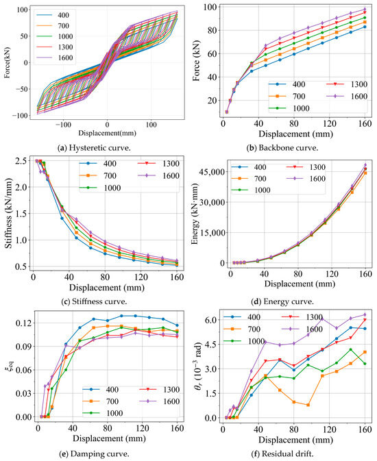
Figure 13.
Influence of Ppss.
From the backbone curves in Figure 13b, it can be observed that increasing the prestressing force of the steel strands produces effects like enlarging the strand area, leading to higher yield and ultimate loads of the joint. The stiffness curves in Figure 13c show a comparable trend: strand prestress has little influence on the joint stiffness before yielding, but after yielding, higher prestress levels result in greater stiffness.
As shown in Figure 13d, higher strand prestress slightly enhances the energy dissipation capacity of the joint, although the effect is relatively limited. Figure 13e further indicates that when the strand prestress is low, the joint exhibits greater equivalent damping. This observation is consistent with the case of a smaller strand area, where the SMA bars carry a larger portion of the load, leading to greater deformation and improved energy dissipation capacity.
Regarding residual deformation, the results shown in Figure 13f indicate that both very high and very low prestress levels lead to larger residual drifts, whereas a moderate prestress level minimizes residual deformation. This finding highlights the importance of selecting an appropriate strand prestress to effectively control the residual deformation of the joint.
3.5. Influence of SMA Bar Area
In the baseline joint model, the SMA bar area was set to 800 mm2, determined from the experimental configuration in which four SMA bars with a diameter of 16 mm (corresponding to a cross-sectional area of 200.96 mm2 each) were employed. To investigate the influence of SMA bar area on the mechanical performance of the joint, the SMA area in the model was varied to 200, 400, 1000, 1200, and 1600 mm2. The corresponding analytical results are presented in Figure 14, where the hysteretic curve is illustrated in Figure 14a.
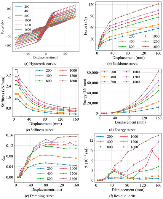
Figure 14.
Influence of ASMA.
As shown in Figure 14b, the SMA bar area influences not only the yield load of the joint but also its ultimate load. In combination with the results in Figure 14c, it can be further observed that the SMA area also affects the initial stiffness of the joint; however, as the displacement increases, the influence of SMA area on joint stiffness gradually diminishes.
From Figure 14d, it is evident that the SMA area has a significant impact on the total energy dissipation of the joint, with larger SMA areas leading to greater energy dissipation capacity. Figure 14e shows that increasing the SMA area likewise enhances the equivalent viscous damping. At the same time, the results in Figure 14f indicate that the residual deformation is almost positively correlated with the SMA area, meaning that larger SMA areas result in greater residual deformation of the joint.
3.6. Influence of SMA Stress
In the baseline joint model, the initial SMA stress was set to 100 MPa. To investigate the influence of SMA stress on the mechanical performance of the joint, the stress level was further varied to 0, 200, 400, and 600 MPa. The corresponding analytical results are presented in Figure 15, where the hysteretic curve is illustrated in Figure 15a.
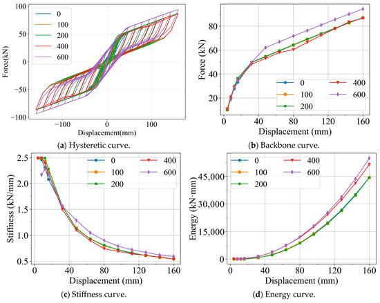
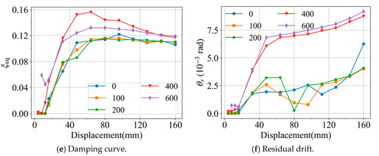
Figure 15.
Influence of PSMA.
As shown in Figure 15b, when the SMA stress is relatively low, it has little effect on the yield and ultimate loads of the joint. However, once the stress exceeds 200 MPa, the yield load decreases while the ultimate load increases. This phenomenon can be attributed to the fact that a higher initial stress in the SMA material causes it to enter the phase transformation stage earlier. The results in Figure 15c further indicate that low SMA stress has no significant influence on the initial stiffness of the joint, whereas excessively high initial stress reduces the initial stiffness. During the loading process, the effect of SMA stress on joint stiffness remains limited.
From Figure 15d,e, it can be observed that higher initial stress enhances the total energy dissipation capacity of the joint and provides greater equivalent viscous damping at small displacement levels. Nevertheless, the results in Figure 15f also reveal that this improvement in energy dissipation comes at the expense of increased residual deformation of the joint.
4. Discussion
The proposed PSS-SMA self-centering joint demonstrated superior seismic performance in both numerical simulations and experimental validation. Comparison between the finite element (FE) model and full-scale experiments indicates that the model can accurately capture the mechanical behavior of the joint throughout different loading stages. Excellent agreement was achieved in terms of initial stiffness, yield load, ultimate load, and unloading stiffness, with discrepancies remaining within an acceptable range. This confirms the reliability and applicability of the FE modeling approach for further parametric investigations.
The parametric analyses reveal that different design parameters exert significant influences on the load-bearing and deformation capacities of the joint. The cross-sectional area and prestressing level of the steel strands play critical roles in both strength and residual deformation. Increasing the strand area effectively enhances the yield and ultimate loads, but the improvement in energy dissipation and equivalent damping becomes marginal, suggesting the need to balance strength and energy dissipation in design. Meanwhile, strand prestress strongly affects initial stiffness and residual deformation. Insufficient prestress fails to provide effective restoring force, whereas excessive prestress may increase residual drift. Thus, selecting an appropriate prestress level is essential for ensuring self-centering performance.
Similarly, the area and initial stress of SMA bars are also decisive factors in joint behavior. A larger SMA area improves energy dissipation and equivalent damping but tends to increase residual deformation. Moderate initial stress levels are most effective in controlling residual drift, while excessively low or high stress reduces overall performance. This highlights the necessity of considering not only the superelastic energy dissipation capacity of SMAs but also its interaction with prestressed steel strands to achieve a balanced performance in terms of strength, dissipation, and recentering capacity.
Overall, by integrating prestressed steel strands with SMA materials, the PSS-SMA joint achieves a well-coordinated balance between load-bearing capacity, energy dissipation, and self-centering ability. The findings confirm its remarkable seismic potential and suitability for application in steel frames located in seismic regions. Nevertheless, further studies are still needed to address durability, material cost, and construction techniques to facilitate large-scale engineering applications.
5. Conclusions
This study investigated a self-centering beam–column joint combining SMA bars and PSSs. The developed FE model matched experimental results with discrepancies within 6%, confirming its accuracy.
The PSS-SMA joint sustained interstory drifts up to 6% while limiting residual drift to <0.2%, with an equivalent viscous damping ratio above 0.10. Compared with SMA-only joints, it achieved over 100% higher yield strength and 70% greater ultimate strength and reduced residual drift by 74%.
Parametric analyses highlighted that increasing strand area or moderate prestress improves strength but has limited effects on damping, while inappropriate prestress increases residual drift. Larger SMA areas enhance energy dissipation but also residual deformation, and excessive SMA initial stress reduces stiffness despite improving damping.
Overall, the PSS-SMA joint balances strength, energy dissipation, and recentering capacity, offering strong potential for seismic-resilient steel frames. Future work should address cost, durability, and constructability for practical implementation.
Author Contributions
Conceptualization, W.L. and Y.F.; methodology, W.L.; software, Y.F.; validation, Y.F.; formal analysis, Y.F.; investigation, Y.F.; resources, W.L.; data curation, Y.F.; writing—original draft preparation, Y.F.; writing—review and editing, W.L.; visualization, Y.F.; supervision, W.L.; project administration, W.L.; funding acquisition, W.L. All authors have read and agreed to the published version of the manuscript.
Funding
This research was funded by The National Natural Science Foundation of China, grant number 51778143, and a project funded by the Priority Academic Program Development of Jiangsu Higher Education Institutions, grant number (CE02-1-51).
Institutional Review Board Statement
Not applicable.
Informed Consent Statement
Not applicable.
Data Availability Statement
The datasets generated and analyzed during the current study are available from the corresponding author on reasonable request.
Acknowledgments
The authors would like to thank Southeast University.
Conflicts of Interest
The authors declare no conflicts of interest.
Abbreviations
The following abbreviations are used in this manuscript:
| PSS | Prestressed steel strand |
| SMA | Shape memory alloy |
References
- Costanza, G.; Mercuri, S.; Porroni, I.; Tata, M.E. Shape memory alloys for self-centering applications: A review. Machines 2024, 12, 628. [Google Scholar] [CrossRef]
- Fang, C.; Yam, M.C. Emerging Superelastic SMA Core Damping Elements for Seismic Application. Front. Built Environ. 2023, 8, 953273. [Google Scholar] [CrossRef]
- Siawsh, N.; Peszynski, K.; Vo-Tran, H.; Young, L. Toward the creation of disaster-resilient communities: The Machizukuri initiative—The 2011 Tōhoku Great East Japan Earthquake and Tsunami. Int. J. Disaster Risk Reduct. 2023, 96, 103961. [Google Scholar] [CrossRef]
- Kung, H.-K.; Hsieh, C.-M.; Ho, C.-Y.; Tsai, Y.-C.; Chan, H.-Y.; Tsai, M.-H. Data-Augmented Hybrid Named Entity Recognition for Disaster Management by Transfer Learning. Appl. Sci. 2020, 10, 4234. [Google Scholar] [CrossRef]
- Bruschi, E.; Quaglini, V.; Zoccolini, L. Seismic Upgrade of Steel Frame Buildings by Using Damped Braces. Appl. Sci. 2023, 13, 2063. [Google Scholar] [CrossRef]
- Fang, C.; Wang, W.; Qiu, C. Seismic resilient steel structures: A review of research, practice, challenges and opportunities. J. Constr. Steel Res. 2022, 191, 107172. [Google Scholar] [CrossRef]
- Garlock, M.M.; Sause, R.; Ricles, J.M. Behavior and design of posttensioned steel frame systems. J. Struct. Eng. 2007, 133, 389–399. [Google Scholar] [CrossRef]
- Guerrini, G.; Restrepo, J.I.; Massari, M.; Vervelidis, A. Seismic behavior of posttensioned self-centering precast concrete dual-shell steel columns. J. Struct. Eng. 2015, 141, 04014115. [Google Scholar] [CrossRef]
- Zhang, R.; Wang, W.; Yang, C. Hybrid test and numerical study of beam-through frame enhanced by friction spring-based self-centering rocking core. Eng. Struct. 2023, 274, 115157. [Google Scholar] [CrossRef]
- Ping, B.; Fang, C.; Hu, Y.; Yu, S. Life-cycle cost assessment of conventional and self-centering steel frames in seismic zones: An extra focus on environmental impacts. Eng. Struct. 2025, 325, 119393. [Google Scholar] [CrossRef]
- Moradifard, R.; Alibazi, A.; Shiravand, M.; Gholami, M. Improved performance-based plastic design method for post-tensioned connection systems. Eng. Struct. 2022, 255, 113931. [Google Scholar] [CrossRef]
- Sanches, R.; Mercan, O.; Roberts, B. Experimental investigations of vertical post-tensioned connection for modular steel structures. Eng. Struct. 2018, 175, 776–789. [Google Scholar] [CrossRef]
- Kujawa, M.; Smakosz, Ł.; Iwicki, P.; Perliński, A.; Tejchman, J. Mechanical performance investigations of a post-tensioned inter-module connection in steel buildings. In Structures; Elsevier: Amsterdam, The Netherlands, 2025; Volume 71. [Google Scholar]
- Wolski, M.; Ricles, J.; Sause, R. Experimental Study of a Self-Centering Beam–Column Connection with Bottom Flange Friction Device. J. Struct. Eng. 2009, 135, 479–488. [Google Scholar] [CrossRef]
- Wang, S.; Zhang, T.; Xu, W.; Du, D.; Zhang, Y. Experimental and numerical investigations on novel post-tensioned precast beam-to-column energy-dissipating connections. In Structures; Elsevier: Amsterdam, The Netherlands, 2023; Volume 54. [Google Scholar]
- Zhang, H.; Zhou, X.; Ke, K.; Yam, M.C.H.; Shi, Y.; Zhang, H. Hybrid self-centering connection employing energy dissipation sequences: Experimental study and a structural seismic demand perspective. J. Struct. Eng. 2023, 149, 04023157. [Google Scholar] [CrossRef]
- Qiu, C.; Bai, M.; Liu, J.; Liu, H. Tests of friction dampers with enhanced recentering capability. Eng. Struct. 2025, 326, 119522. [Google Scholar] [CrossRef]
- Rahgozar, N.; Alam, M.S. A novel hybrid self-centering piston-based bracing fitted with SMA bars and friction springs: Analytical study and seismic simulation. J. Struct. Eng. 2023, 149, 04023055. [Google Scholar] [CrossRef]
- Ke, K.; Zhang, H.; Zhou, X.; Yam, M.C.; Wang, Y.; Shi, T. Hybrid Self-Centring Steel Frames: Insights and Probabilistic Seismic Assessment. Eng. Struct. 2024, 303, 117516. [Google Scholar] [CrossRef]
- DesRoches, R.; Taftali, B.; Ellingwood, B.R. Seismic performance assessment of steel frames with shape memory alloy connections. Part I—Analysis and seismic demands. J. Earthq. Eng. 2010, 14, 471–486. [Google Scholar] [CrossRef]
- Speicher, M.S.; DesRoches, R.; Leon, R.T. Experimental Results of a NiTi Shape Memory Alloy (SMA)-Based Recentering Beam–Column Connection. Eng. Struct. 2011, 33, 2448–2457. [Google Scholar] [CrossRef]
- Kazemi, F.; Jankowski, R. Enhancing seismic performance of connections equipped with SMA bolts incorporating nonlinear soil–structure interaction. Eng. Struct. 2023, 274, 114896. [Google Scholar] [CrossRef]
- Mo, Z.; Feng, Q.; Lai, B.L.; Jiang, W.-Q.; Feng, Y. Resilient performance of super-elastic SMA bolted connection with extended end plate and shear tab. J. Constr. Steel Res. 2022, 199, 107626. [Google Scholar] [CrossRef]
- Feng, Y.; Li, W. Seismic performance of SMA-prestressed self-centering beam–column joints: Experimental and numerical study. J. Constr. Steel Res. 2025, 226, 109272. [Google Scholar] [CrossRef]
- Fang, C.; Qiu, C.; Wang, W.; Alam, M.S. Self-centering structures against earthquakes: A critical review. J. Earthq. Eng. 2023, 27, 4354–4389. [Google Scholar] [CrossRef]
- Kamaris, G.S.; Papavasileiou, G.S.; Kamperidis, V.C.; Vasdravellis, G. Residual Drift Risk of Self-Centering Steel MRFs with Novel Column Bases at Near-Fault Regions. Soil Dyn. Earthq. Eng. 2022, 162, 107391. [Google Scholar] [CrossRef]
- Chen, Z.; Niu, X.; Liu, J.; Khan, K.; Liu, Y. Seismic study on an innovative fully-bolted beam–column joint in prefabricated modular steel buildings. Eng. Struct. 2021, 234, 111875. [Google Scholar] [CrossRef]
- Erochko, J.; Christopoulos, C.; Tremblay, R.; Choi, H. Residual drift response of SMRFs and BRB frames in steel buildings designed according to ASCE 7-05. J. Struct. Eng. 2011, 137, 589–599. [Google Scholar] [CrossRef]
- Ricles, J.M.; Sause, R.; Garlock, M.M.; Zhao, C. Posttensioned seismic-resistant connections for steel frames. J. Struct. Eng. 2001, 127, 113–121. [Google Scholar] [CrossRef]
- Christopoulos, C.; Filiatrault, A.; Uang, C.M.; Folz, B. Posttensioned energy dissipating connections for moment-resisting steel frames. J. Struct. Eng. 2002, 128, 1111–1120. [Google Scholar] [CrossRef]
- Ricles, J.M.; Sause, R.; Peng, S.W.; Lu, L.W. Experimental evaluation of earthquake resistant posttensioned steel connections. J. Struct. Eng. 2002, 128, 850–859. [Google Scholar] [CrossRef]
- Palermo, A.; Pampanin, S.; Marriott, D. Design, modeling, and experimental response of seismic resistant bridge piers with posttensioned dissipating connections. J. Struct. Eng. 2007, 133, 1648–1661. [Google Scholar] [CrossRef]
- Nia, M.M.; Moradi, S.; Yang, T. Performance-based seismic design of self-centering steel moment frames with SMA-bolted connections. J. Constr. Steel Res. 2023, 208, 107990. [Google Scholar] [CrossRef]
- Yun, C.; Chao, C.; Cong, C. Study on seismic performance of prefabricated self-centering beam to column rotation friction energy dissipation connection. Eng. Struct. 2021, 241, 112136. [Google Scholar] [CrossRef]
- Venture, SAC Joint. Protocol for Fabrication, Inspection, Testing, and Documentation of Beam-Column Connection Tests and Other Experimental Specimens. SAC Report SAC/BD-97/02. 1997. Available online: https://bibliotecadigital.uchile.cl/discovery/fulldisplay?vid=56UDC_INST:56UDC_INST&docid=alma991006340659703936&context=L (accessed on 10 November 2025).
- Mokhtarnejad, N.; Garmeh, V.; Shariatmadar, H.; Askariani, S.S. Numerical study of a novel SMA-based self-centering beam-to-column connection. In Structures; Elsevier: Amsterdam, The Netherlands, 2023; Volume 47. [Google Scholar]
- Huang, J.; Zhu, S.; Wang, B. Self-centering steel beam-to-column connections with novel superelastic SMA angles. J. Constr. Steel Res. 2024, 214, 108458. [Google Scholar] [CrossRef]
- Yun, C.; Chao, C. Study on seismic performance of prefabricated self-centering steel frame. J. Constr. Steel Res. 2021, 182, 106684. [Google Scholar] [CrossRef]
- Scott, M.H.; Fenves, G.L. Plastic hinge integration methods for force-based beam–column elements. J. Struct. Eng. 2006, 132, 244–252. [Google Scholar] [CrossRef]
- Chen, P.; Xu, L.; Li, Z. Modeling methods of self-centering energy dissipation braces using OpenSees. J. Constr. Steel Res. 2022, 193, 107267. [Google Scholar] [CrossRef]
- Carreño, R.; Lotfizadeh, K.H.; Conte, J.P.; Restrepo, J.I. Material model parameters for the Giuffrè-Menegotto-Pinto uniaxial steel stress-strain model. J. Struct. Eng. 2020, 146, 04019205. [Google Scholar] [CrossRef]
- Liu, J.; Peng, Z.; Guan, D.; Lin, Y. Experimental Investigation of Precast Rocking Walls Incorporating Tension-Compression and Shear Steel Energy Dissipaters. Appl. Sci. 2023, 13, 8817. [Google Scholar] [CrossRef]
- GB/T 5224-2014; Steel Strand for Prestressed Concrete. Standardization Administration of China, Standards Press of China: Beijing, China, 2014.
Disclaimer/Publisher’s Note: The statements, opinions and data contained in all publications are solely those of the individual author(s) and contributor(s) and not of MDPI and/or the editor(s). MDPI and/or the editor(s) disclaim responsibility for any injury to people or property resulting from any ideas, methods, instructions or products referred to in the content. |
© 2025 by the authors. Licensee MDPI, Basel, Switzerland. This article is an open access article distributed under the terms and conditions of the Creative Commons Attribution (CC BY) license (https://creativecommons.org/licenses/by/4.0/).