Article

Research into Driving Stability of an SUV–Trailer Combination for Driving Maneuvers by Simulation Computations

1
Department of Transport and Handling Machines, Faculty of Mechanical Engineering, University of Žilina, Univerzitná 8215/1, 010 26 Žilina, Slovakia
2
Department of Technological Engineering, Faculty of Mechanical Engineering, University of Žilina, Univerzitná 8215/1, 010 26 Žilina, Slovakia
*
Author to whom correspondence should be addressed.
Appl. Sci. 2025, 15(22), 11918; https://doi.org/10.3390/app152211918 (registering DOI)
Submission received: 27 September 2025 / Revised: 4 November 2025 / Accepted: 6 November 2025 / Published: 9 November 2025
(This article belongs to the Special Issue New Challenges in Vehicle Dynamics and Road Traffic Safety)

Abstract

Operation of vehicle–trailer combinations is currently popular throughout many countries. Connecting a trailer to a passenger car increases the car’s utility value because it is possible to transport more goods over shorter or longer distances. Trailers are also popular as caravans, which provide a home on wheels during holiday periods. As a trailer is connected to a towing vehicle by means of a spherical joint from the mechanics’ point of view, a vehicle–trailer combination has significantly different driving properties in comparison with a sole vehicle. These differences are manifested mainly while driving in a curve as lower stability of the vehicle. In this case, the lower stability is considered an uncontrolled sway motion. This study is focused on researching the driving stability of a vehicle–trailer combination regarding the sway motion problem. The research is fully performed by means of simulation computations in a commercial multibody simulation software. The investigated vehicle–trailer combination consists of an SUV passenger car and a single-axle goods trailer. Two model driving maneuvers are investigated, namely bypassing an obstacle in a lane and changing lanes on a road. Simulation computations are performed for chosen loads of the trailer and for a different position of the center of gravity of the load in the single-axle trailer. The performed research has proven that the applied simulation computations represent a robust tool to investigate real tasks related to vehicle safety without performing expensive and dangerous tests. Very important findings include identifying the proper position of the center of gravity of the load on the trailer to ensure safe driving properties for driving maneuvers that could pose potential danger during real operation.

1. Introduction

In all areas of everyday life, more and more emphasis is placed on safety every year. The automotive industry is no different. An increasing number of cars can be seen on our roads. This also increases the need to transport goods for personal use, whether it is the transport of cars from so-called imports on a car transporter, the transport of smaller boats behind a vehicle on holiday, towing a caravan, or simply transporting materials on a classic trailer. Each of the aforementioned types of transport has its own specifics, whether in terms of road traffic rules, the maximum weight of the transported load or the distribution of the load within the trailer [1,2,3].
Trailers are already an integral part of the vehicle fleet in many countries. They are mainly used for transporting goods. Currently, trailers are produced in various weight and size categories. Trailers are connected to the towing vehicle, which increases the utility properties of the vehicle. The trailer is connected via a ball-shaped towing device mounted on the vehicle. This means that the vehicle and the trailer are connected to each other via a ball joint, which allows rotation around all three axes [4]. From a mechanical point of view, the vehicle–trailer combination becomes a mechanism with significantly different kinematic properties than a separate vehicle without a trailer. This fact is then reflected in the mechanics of the movement of the combination itself. Experience shows that the trailer-connecting-to-a-vehicle combination affects the behavior of the vehicle when performing driving maneuvers. This is especially true when driving in a curve, when suddenly changing direction (e.g., suddenly changing lanes), but also when overtaking another vehicle on the road or going around an obstacle on the road. These described driving maneuvers can cause unstable movement of the vehicle combination and generate a movement known as sway movement. It has been found that the instability of the vehicle combination in these situations is mainly influenced by the position of the center of gravity of the load on the trailer or the position of the center of gravity of the trailer (considering the load). In addition to the driving maneuvers mentioned above, sway movement can also occur due to the presence of unevenness on the road over which the trailer passes [5,6].
In the event of a sway motion, the vehicle with the trailer performs a wavy motion relative to the axis in the driving direction of the vehicle combination. When the sway motion of the vehicle combination is excited, it is very difficult to calm the vehicle combination so that the motion is damped [7,8]. When excited, the oscillation amplitudes most often increase relatively quickly, which leads to a serious accident of the vehicle combination. Examples of several such situations can be seen captured on video. An example of an unstable sway motion of the vehicle–trailer combination is shown in Figure 1. It shows the main phases of movement and the increase in the amplitude of the sway motion in the horizontal plane in the driving direction. As can be seen, the unstable motion could no longer be reversed by any intervention of the driver in the steering system, and a traffic accident occurred.
As can be seen in Figure 1, uncontrolled sway motion of the SUV–trailer combination led to a serious road accident. It caused damage not only to the SUV–trailer itself but also directly endangered the safety of other road users.
Hence, the main motivation of the research is to reveal possibilities to analyze the driving properties of the chosen SUV–trailer combination in a safe, available and inexpensive way through simulation computations.
The presented research includes a multibody model of a particular SUV vehicle and a single-axle trailer. These models come from real vehicles, i.e., they have parameters that correspond to real vehicles. Two driving maneuvers are simulated, which are responsible for road accidents of vehicle–trailer combinations regarding loss of stability. The research brings a comparison of load configurations that happen in real life due to drivers’ inattention regarding the correct distribution of the load on the trailer. The research includes an assessment of the driving stability of the SUV–trailer combination for two driving maneuvers at different loads and driving speeds, as follows:
  • Maneuver A: driving the SUV–trailer combination while bypassing an obstacle in a lane: The load of 500 kg on the trailer is examined and compared with the 1000 kg load. Further, the influence of a change in the position of the center of gravity of the trailer load in the longitudinal direction on driving stability is evaluated;
  • Maneuver B: driving the SUV–trailer combination while changing lanes: Three driving speeds are defined for the SUV–trailer combination and their influence on driving stability is assessed. The defined driving speeds are 80 km/h, 110 km/h and 130 km/h.
The dynamic properties of vehicles are evaluated from several points of view. There are standards to do this. However, when the driving properties of a vehicle–trailer combination are investigated and assessed, no standards are available to describe the stability criteria for the analyzed SUV–trailer combination. This is the reason that a hybrid threshold system is used by researchers in this field. The following criteria are considered in the hybrid threshold system:
  • The limit value of the lateral acceleration: ay ≤ 0.4∙g, which ensures the vehicle–trailer combination remains within the controllability limit [10], where g is gravitational acceleration;
  • The yaw instability threshold:|ψ| ≤ 15° according to NHTSA 809-433. This maneuver is originally designed to quantify on-road, untipped rollover properties [11], and it is to evaluate the prevention of trailer sway;
  • The deviation of the angle: Δφ < 180°, in order to maintain a phase coupling between bodies [12].
These three criteria are applied to vehicles that belong to the category M1/N in combination with vehicles belonging to category O1/O2. They are summarized in Table 1.

2. Literature Review

The solved problem is the subject of research of scholars and researchers in universities and institutions focused on the automotive industry as well as on mechanics of transport means. There are published contributing works and studies focused on analysis of various types of vehicle–trailer combinations as well as on systems to eliminate unfavorable effects arising during vehicle–trailer combinations.
Robat et al. [13] present the study of a tractor-trailer wheeled mobile robot model, whose wheels may slip in lateral and longitudinal directions. They applied the Lagrange’s formalism in the research. Together with this, the problem of path following for the trailer was addressed as well as the partial feedback linearization technique. However, the work includes research about a single-axle tractor and a single-axle trailer combination.
The research by Harlecki et al. [14] includes the development of a mathematical model of a truck-trailer combination dynamics and the results of the study of road traffic conditions while performing typical road maneuvers and changing design parameters and the load of the trailer. The mathematical model, similarly to our mathematical model included in Section 3, can be treated as a virtual prototype of the equations’ system. However, this research is focused on a heavy vehicle–trailer combination.
The study by Ta et al. [15] is also aimed at the heavy truck-trailer combination and its dynamics while driving a curve. The study includes a full dynamic model of a tractor and semi-trailer combination developed based on the multibody simulation analysis and Newton–Euler equations. An application of the model should serve for determination of the rollover indicators for the solved scenarios.
The research [16] is already focused on an interesting as well as relatively difficult problem of a phase portrait-based sliding mode control method for a car-trailer combination. They established a new non-linear single-track model with three degrees of freedom, which is integrated into the used controller design. The authors stated that the proposed method has superior performance in enhancing the dynamic stability of a vehicle–trailer combination.
The research presented by Zhang et al. [17] deals with a proposal of an innovative path-planning method designed for vehicle–trailer combinations with intelligent semi-trailers. The method is tailored for heavy-duty semi-trailers on straight road alignments. The roll stability boundary for a car is established, and a multi-objective cost function for selection of an optimal path is designed. The method works within the considered requirements for roll stability of an intelligent semi-trailer, and it improves the semi-trailer stability during lane changing. At the same time, it provides robust support for efficient and safe operation of a truck and a semi-trailer combination.
The work [18] by Wang et al. provides results of research about tuning of damping of a trailer suspension system on rearward amplification of a vehicle–trailer combination. The research team found that smaller values of the damping coefficient of the trailer damper lead to smaller rearward amplification, and this improves driving safety. When the damping coefficient of the trailer damper is larger, responses of a trailer during driving are quicker to towing car inputs.
Similarly to our investigated cases, the authors Molnár and Kun [19] evaluated the dynamic behavior of a mechanical system of a vehicle–trailer combination by means of a Kistler force and torque measurement device, which was mounted on the vehicle’s wheels. The position of the center of gravity of the load on a trailer was changed to investigate vehicle stability and handling. Based on the presented study, it is not clear whether the research was performed using a real vehicle–trailer combination or using a scaled model. The basic conclusion is that the position of the load center of gravity on a trailer affects the handling and maneuverability of a vehicle–trailer combination while performing a double lane change maneuver.
Relatively extensive research about driving properties of a vehicle–trailer combination is provided in work [20]. The researchers focused on the integration of a torque-vectoring system and an active suspension system on a towing vehicle to provide yaw rate tracking, sideslip angle limitation and reduction of trailer sway. The research includes analyses of several alternative real-time implementable non-linear model predictive control algorithms using either the predicted dynamics of a trailer hitch or the estimated forces of a hitch joint to control an electric all-wheel-drive car towing a semi-trailer. The presented approach requires the implementation of an intelligent system installed on a vehicle board and leads to a more complicated system of controlling vehicle–trailer combination driving.
Viganico et al. investigated in the research [21] the limits of the main handling and stability parameters of a tractor semi-trailer based on selected maneuvers, namely double lane change, steady-state cornering and tilt table rotation. The research was performed by means of multibody simulation software. Moreover, the simulation results were validated experimentally, where the root-mean-square values of the rolling angle and lateral acceleration at the chosen speeds were chosen. The results of the research contribute to assessment of safety of the lateral dynamics of a vehicle and a semi-trailer combination.
The research by Oh and Choi [22] closely relates to our research. The study [22] includes comprehensive analyses of the lateral behavior characteristics of a light vehicle–trailer combination affected by variations of tongue weight. They stated that the optimal tongue weights for the stability and consistency of the nominal system of a vehicle–trailer combination are 22.61% and 48.61% of the trailer weight, respectively.
The application of advanced technologies to vehicles is becoming more frequent. These technologies are based on wide research and use available modern technologies supported by electronic systems installed in vehicles. As addressed in the research by Viadero-Monaterio et al. [23], the MIMO method (multi-input multi-output) is a prospective method for path tracking control of autonomous vehicles under network-induced delays while taking into account the roll dynamics to improve both driving safety and passenger comfort. The research team also introduced the study on the problem of integrated motion planning and trajectory tracking for multiple intelligent vehicles in unsignalized intersections [24]. The research is based on evaluation of co-simulations with Simulink and Unreal Engine. Further, a study about driving safety of vehicle platooning is solved in the works [25,26], where the driving conditions and their effects on vehicles and drivers’ behaviours are examined. As included in the research [27], the Internet of Things can play an important role in estimation of sideslip angle and roll stability of vehicles.
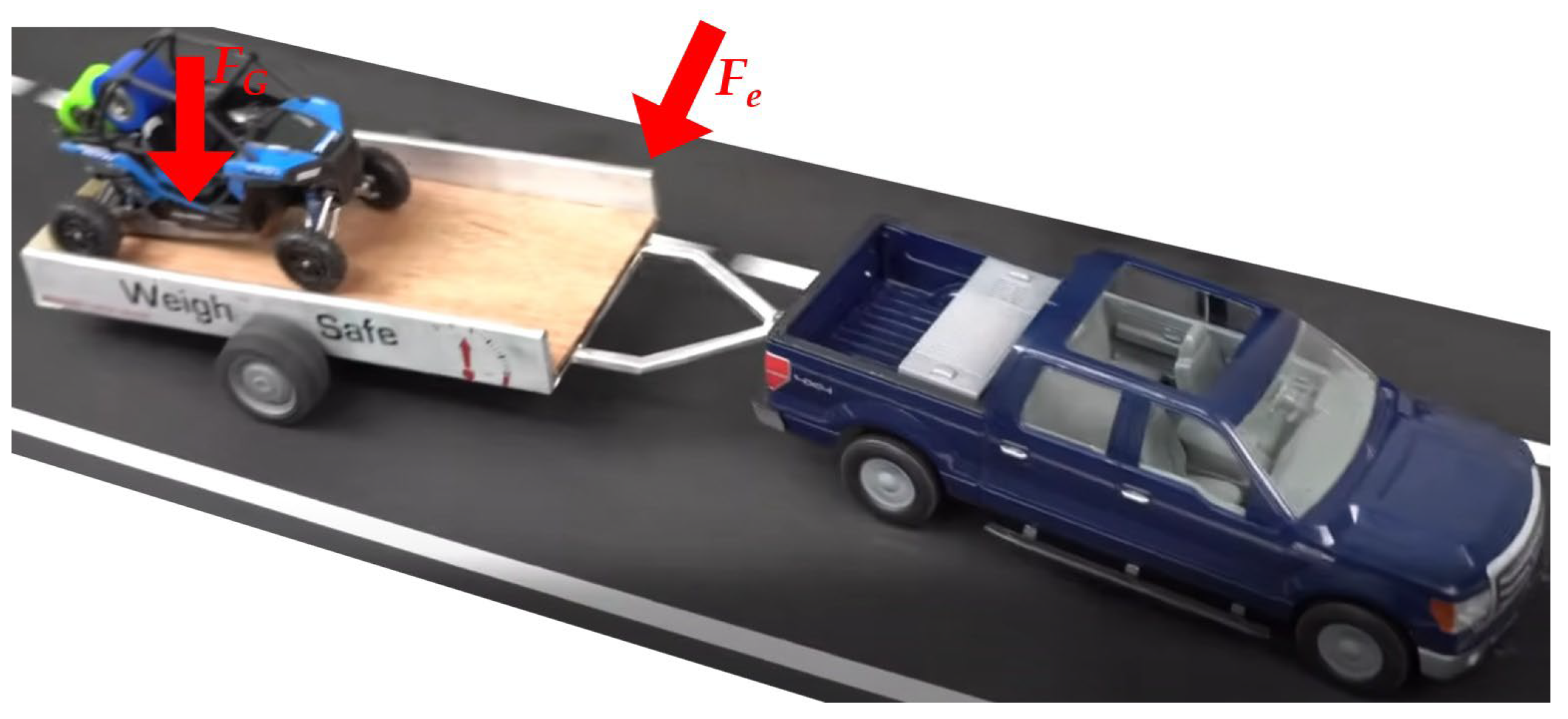
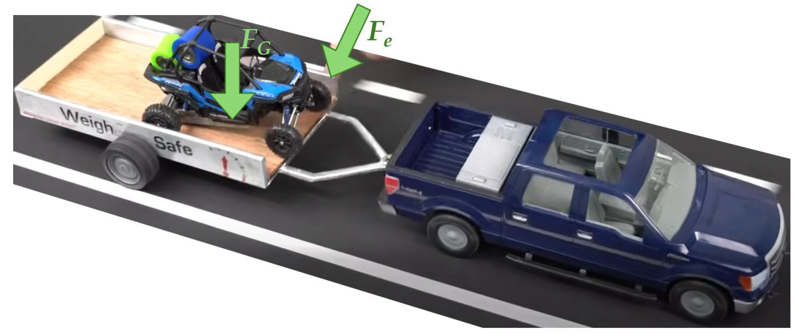
Based on the presented review of the available results of the research, the solved problem of driving stability is current. The research is performed most often by means of simulation computations, because such an approach allows saving time to prepare an object of the investigation. Further, experimental tests are more expensive, and mainly they are dangerous. There are also experiments with scaled models. However, they also require costs to build a suitable test bench. The most known experiments with scaled models are focused on investigation of the influence of the center of gravity of the load on a trailer. Examples of these experiments are depicted in Figure 2 and Figure 3 and they are available on the webpages [28,29,30]. The scaled model of a vehicle–trailer combination is ensured in the front part, and it is placed on a moving conveyor. When the center of gravity (marked by the gravitational force FG) of the trailer is in its rear half, after acting the lateral excitation force Fe, the vehicle–trailer combination movement is unstable, and there is risk of an accident (Figure 2). When the center of gravity of the trailer is placed on the front part of the trailer, despite acting the lateral excitation force Fe on the trailer, the movement is stabilized after a short time (Figure 3).
Based on the analyzed existing research activities and the topicality of the problem, the research team decided to investigate the driving stability of the SUV–trailer combination. As the research team has long-term experience in the field of simulation computations as well as in performing experiments [31,32,33,34], it was decided to use the commercial multibody simulation software Simpack, version 2024.3 (Dassault Systèmes, Vélizy-Villacoublay, France) for the research. The investigation of the SUV–trailer combination stability includes analyses of the SUV–trailer combination driving stability while bypassing an obstacle on the road and while changing lanes on the road. The essential factor analyzed is the position of the load on the trailer, in other words, the position of the center of gravity of the trailer. Additionally, various driving speeds were chosen for individual analyzed cases. A presentation of the created multibody model is included in Section 3, and the achieved results as well as the discussion are included in Section 4.

3. A Simulation Model of the SUV–Trailer Combination

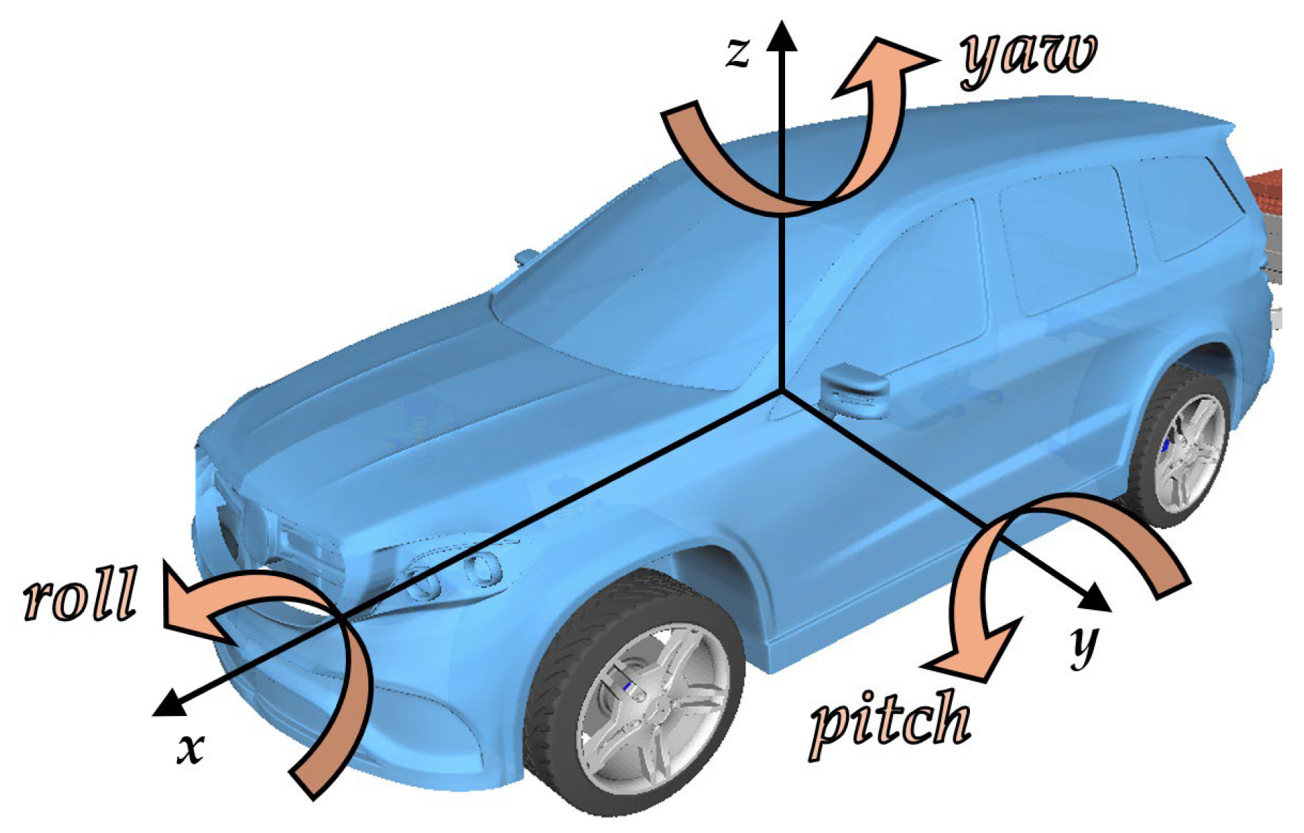
The research of the driving stability of the vehicle–trailer combination was performed with the SUV vehicle and with the one-axle trailer. The multibody models of the SUV vehicle and the trailer were setup in the commercial MBS software Simpack, version 2024.3 (Dassault Systèmes, Vélizy-Villacoublay, France). This software is widely used for analysis of driving properties not only of road vehicles, but also for other types of transport means (rail vehicles, planes, etc.) as well as manipulation machines. It allows the creation of a complex multibody model through an interface. The great advantage of this software is that non-linearities of parameters can be defined in a quite simple way. Moreover, large deflections are considered. Further, it is possible to simulate driving a vehicle and a trailer on a road as in reality. Basic angular movements of the vehicle in space are marked in Figure 4.

3.1. Parameters of the SUV Car

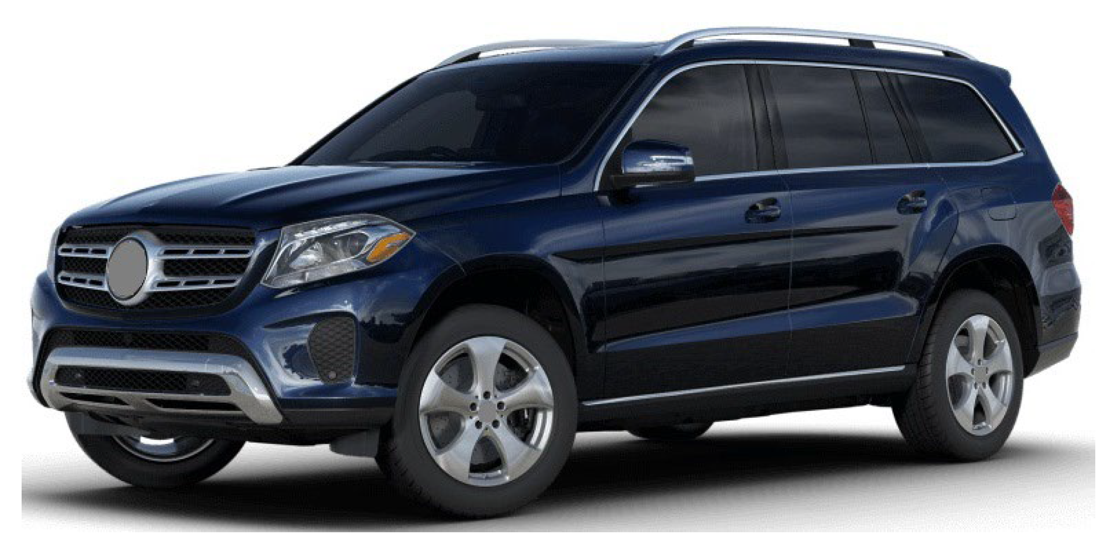
An SUV car of the high category (or the luxury category) was chosen as the examined vehicle. It is illustrated in Figure 5. It was considered that the vehicle is equipped with a diesel engine. It is the most common option for the car operated in the authors’ region.
The main dimensional parameters of the SUV car are listed in Table 2, and Table 3 includes its main mass parameters.
The SUV car has a double wishbone front axle type, and the rear axle is the multilink type. This high-category SUV car has the tire dimensions 295/40 R21, which means that the tire width is 295 mm and the rim diameter is 21 inches. The number 40 marks the ratio of the tire height to the tire width.
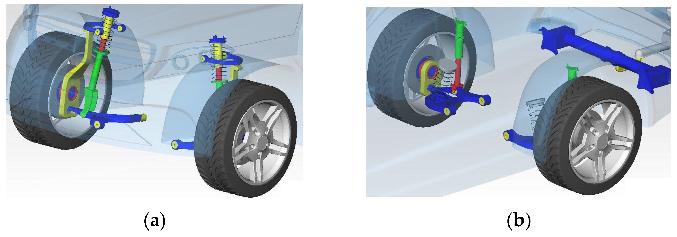
The MBS model of the SUV car includes rigid bodies. Deformable bodies were not considered because it was assumed that the flexibility of bodies in the model would not influence the performed driving manoeuvres significantly. In the case of rigid bodies, it is necessary to define the centre of gravity of individual bodies. Further, masses and moments of inertia are prescribed. The bodies’ geometry was created in the 3D software Catia, version V5-62022 (Dassault Systèmes, Vélizy-Villacoublay, France). The rigid bodies of the model are connected to each other by means of massless flexible elements. These are the components of the suspension system, i.e., springs and dampers. Further, mechanical joints and kinematic constraints are used to make couplings between corresponding rigid bodies. Sensors, as other necessary modelling elements, are also defined in the software interface. Figure 6 depicts a spatial MBS model of the SUV car, and details of the front axle and the rear axle are shown in Figure 7.

3.2. Parameters of the Trailer

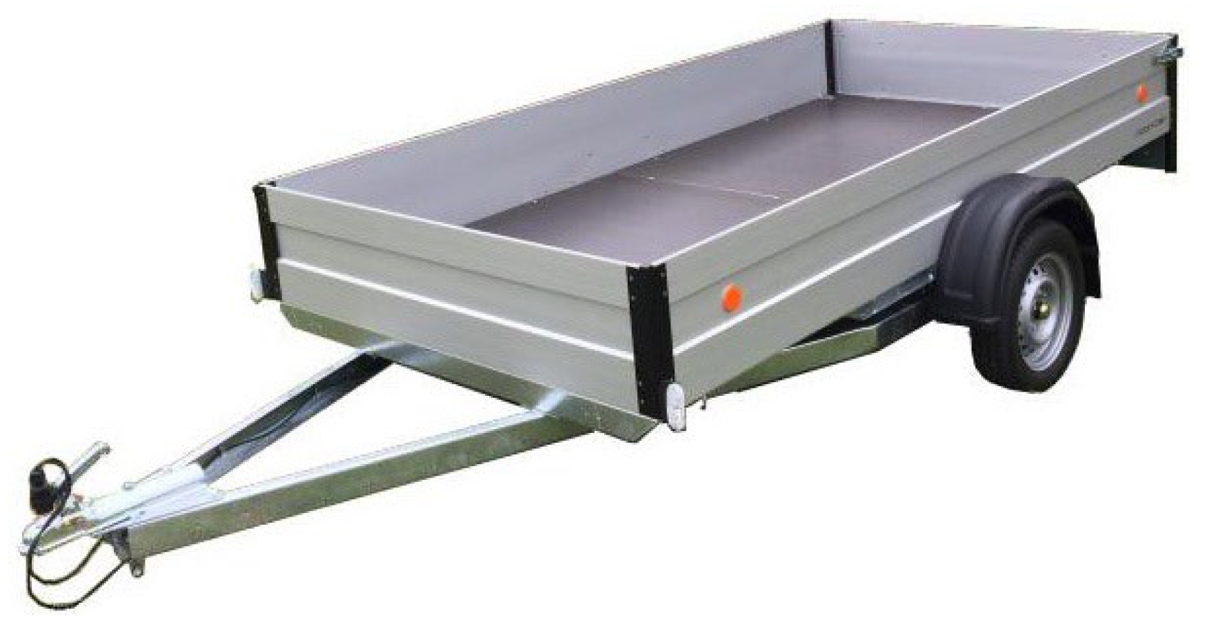
The other part of the examined vehicle–trailer combination is a trailer. It is a single axle trailer, which is connected to the SUV car by means of a tow hitch. The real trailer, which the multibody model comes form, is depicted in Figure 8.
This trailer type was chosen because it is the most often used one for its availability, price and compact dimensions.
The MBS model of the trailer also includes only rigid bodies, namely two wheels, swinging arms of the axle and the frame. The trailer model is a simpler one from the modelling point of view. Regarding flexible massless elements, the trailer includes modelling elements for a suspension system. The position of the swinging arms is retained in the axle beam by rubber elements. These rubber elements ensure stiffness-damping characteristics of the trailer.
The dimensional parameters of the trailer are included in Table 4 and the mass properties of the trailer are listed in Table 5.
Figure 9 depicts the MBS model of the trailer created in the Simpack software as well as the detail of the swinging arm axle.
This trailer is equipped with wheels with the tire dimensions 165/70 R13, i.e., the tire width is 165 mm, the wheel radius is 13 inches and the profile number 70.
Once the SUV MBS model and the trailer MBS model are created as substructures, the entire vehicle–trailer combination can be set up. The trailer is connected to the car as in the reality. It means that the spherical mechanical joint is applied. In total, the vehicle–trailer multibody model includes 24 rigid bodies. The illustration of the SUV–trailer combination in the Simpack software is shown in Figure 10.
The driving maneuvers were examined for a different position of the load on the trailer. For this purpose, three pallets with bricks were modelled. These pallets were placed on the loading area of the trailer superstructure. This can be seen in Figure 11.
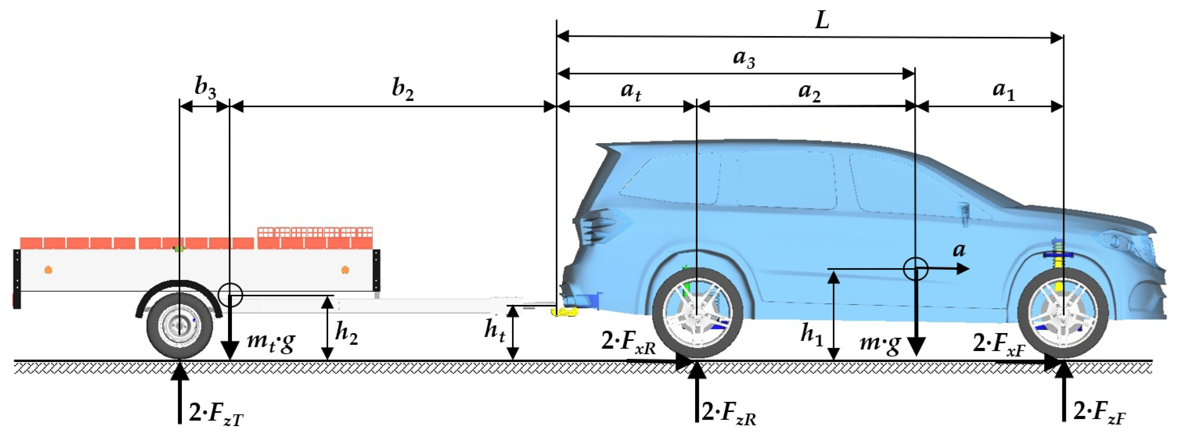
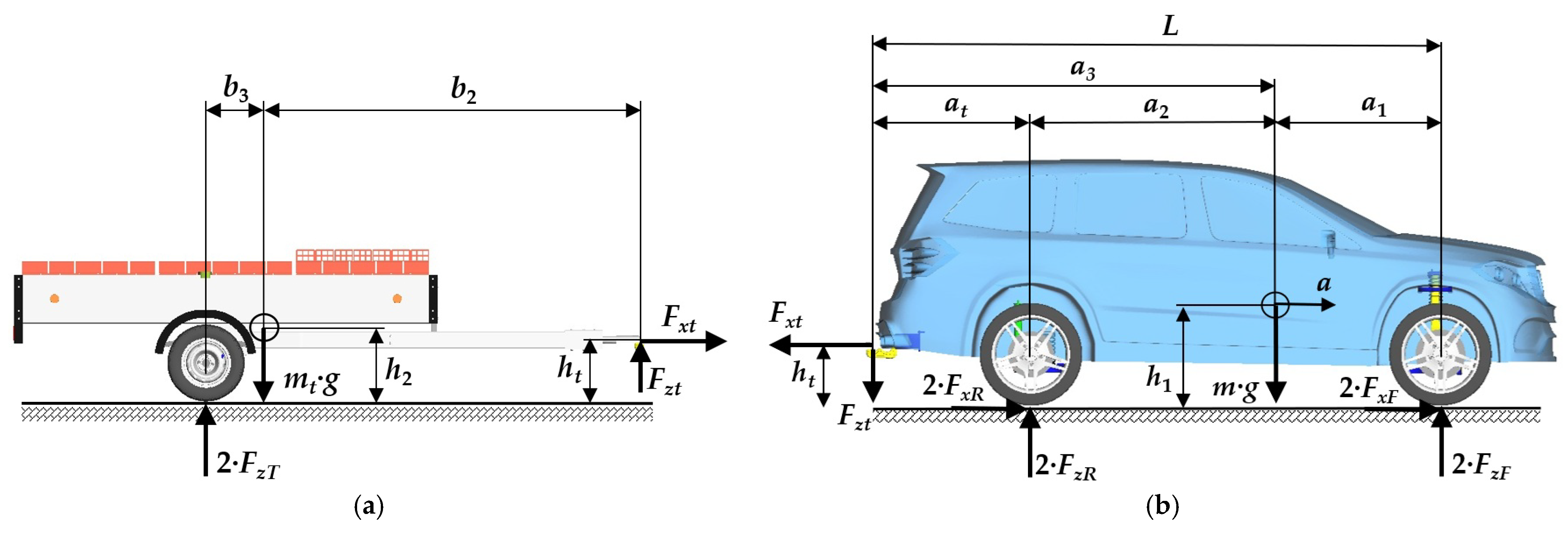
A dynamic model of the SUV–trailer combination while driving on a straight track is shown in Figure 12. The SUV–trailer combination drives with acceleration a. It is needed to divide the model of the SUV–trailer combination into two individual parts, as is depicted in Figure 13. There is possible to see the normal and tangential forces in the tire/road contact together with the forces acting in the tow hitch. These forces are marked as Fxt and Fzt. Note: The parameters of the SUV–trailer combinations are listed in Table 1.
Further, the following heights are marked: h1 is the SUV–vehicle center of gravity height, h2 is the trailer center of gravity height and ht is the tow hitch height. L is the wheelbase. The gravitational forces act on individual vehicles, i.e., on the SUV–vehicle (mg) as well as on the trailer (mtg). It is possible to derive the equations of motion of the SUV–trailer combination based on the Newton’s law of motion on a straight track. The equations of motion in the longitudinal direction are for the SUV–vehicle (Equation (1)) and for the trailer (Equation (2)) as follows:
i F i x = m a
i F i x t = m t a
A general equation of the static equilibrium of forces in the z-axis (Figure 6) (Equation (3)) and an equation of the static equilibrium of moments around the y-axis (Figure 6) (Equation (4)) have the same general form for both the SUV–vehicle and the trailer as follows:
i F i z = 0
i M y = 0
After writing down the general equation of motion and the equations of static equilibrium, the following relations (Equation (5)) arise for the trailer (Figure 13a):
F x t = m t a , 2 F z T m t g + F z t = 0 , F z t b 2 2 F z T b 3 + F x t h 2 h t = 0
Decomposed relations of the equation of motion and equations of static equilibrium for the SUV–vehicle are written below (Equation (6)). They are more complicated due to the investigation of the vehicle with two axles (in comparison with the single-axle trailer) as well as due to traction tangential forces FxF and FxR acting on the drive wheels of the SUV vehicle (Figure 13b):
2 F x F + 2 F x R F x t = m a , 2 F z F + 2 F z R F z t m g = 0 , 2 F z F a 1 2 F z R a 2 + 2 F x F h 1 + 2 F x R h 1 + F z t a 2 + b 1 F x t h t h 1 = 0 .
While the acceleration a is a known quantity, the unknown quantities that need to be calculated are the forces FxF + FxR, FzF, FzR, FzT, Fxt, Fzt, and their expression is as follows:
F x F + F x R = a m t + m 2 , F z F = m g L m g a 1 a h t m + h 1 m t 2 L + m t g b 3 a h 2 h 1 b 1 2 b 2 + b 3 , F z R = m g a 1 + a h t m + h 1 m t 2 L + m t g b 3 a h 2 h 1 L + b 1 2 L b 2 + b 3 , F z T = m t g b 3 a h 2 h 1 2 b 2 + b 3 , F x t = m t a , F z t = m t g b 3 a h 2 h 1 b 2 + b 3 .
Figure 14 shows the SUV–trailer combination after eigenvalue analysis. Three load states are depicted in this figure, namely the empty trailer (Figure 14a), the fully loaded trailer with the center of gravity in front of the trailer axle (Figure 14b) and the fully loaded trailer with the center of gravity behind the trailer axle (Figure 14c). The eigenfrequencies belonging to these eigenmodes are listed in Table 6. As can be seen from the eigenanalysis results, the eigenfrequencies are almost the same for all three load states. Despite that, the SUV–trailer combination with the empty trailer has the highest value of the eigenfrequency.
The mathematical model of the solved SUV–trailer combination is set up automatically in the used multibody software. It comes from known models presented in [35,36,37,38,39]. The great advantage of the software is that a user can define the rigid bodies with their mass and inertia properties, center of gravity and couplings between these bodies. The derived mathematical model of the SUV–trailer has 24 mechanical couplings. Additionally, 12 kinematic couplings are defined to restrict movements between bodies. Hence, the mathematical model of the SUV–trailer combination and its movements are described by a system of equations. This system of equations includes differential equations (they are non-linear due to suspension system characteristics as well as large angular deflections allowed) as well as algebraic equations. Then, the resulting mathematical description is formed by differential-algebraic equations, known as DAE. Their solution is performed by the software solver with the defined parameters.
As mentioned above, the multibody model of the SUV–trailer combination includes rigid bodies. Further, these bodies are connected by means of massless connecting elements, namely mechanical joints, kinematic couplings, springs, dampers and bump stops. Flexibility of the mechanical joints and kinematic couplings were not considered in the model. Further, the tire model used in the simulation computations was based on the Pacejka similarity method [40,41]. This model is standardly used, and thanks to its simplicity, it is relatively fast. It represents pure slip conditions well, including the camber angle influence. It is important to note that any crosswind (and other aerodynamic interaction) was not defined in the model. This means that drag was not considered. Nor were external factors, namely uneven tire grip in the tire/road model, considered.

4. Simulation Computations of the Driving Maneuvers and the Results

In this section, the research results of the simulation computations of the SUV–trailer driving for the chosen driving maneuvers are presented. Namely, two driving maneuvers were investigated:
  • Driving the SUV–trailer combination while bypassing an obstacle on a lane;
  • Driving the SUV–trailer combination while changing a lane.
The research results are presented in a form of graphs supplemented with illustrations of the SUV–trailer combination in an important time moment. Both driving maneuvers are assessed based on the SUV–trailer combination response for different loading conditions of the trailer.

4.1. Driving the SUV–Trailer Combination While Bypassing an Obstacle on a Lane—Maneuver A

Sudden bypassing of an obstacle on a road lane can be dangerous for a sole car while no trailer is towed. However, when a car tows a trailer (even a loaded trailer), such bypassing of an obstacle can be more dangerous. This is mainly due to the more difficult maneuverability of the car-trailer combination and due to the combination braking (the braking distance is longer).
The track geometry for the maneuver was derived from the road geometry for the moose test. The moose test is a driving maneuver that came to public attention in 1997 [ISO 3888-2] [41]. As the car–trailer combination is not examined only as a sole car, the parameters of the road geometry are slightly changed. This is obvious from Figure 15 and Figure 16, where Figure 15 depicts the track geometry for the moose test and Figure 16 shows the geometry used in the simulation computations.
Three driving cases were evaluated for the Maneuver A, namely:
  • Case 1: the driving speed of 40 km/h, the load of 1000 kg;
  • Case 2: the driving speed of 50 km/h, the load of 500 kg;
  • Case 3: the driving speed of 55 km/h, the load of 500 kg.
These driving cases are evaluated based on the criteria listed in Table 1.
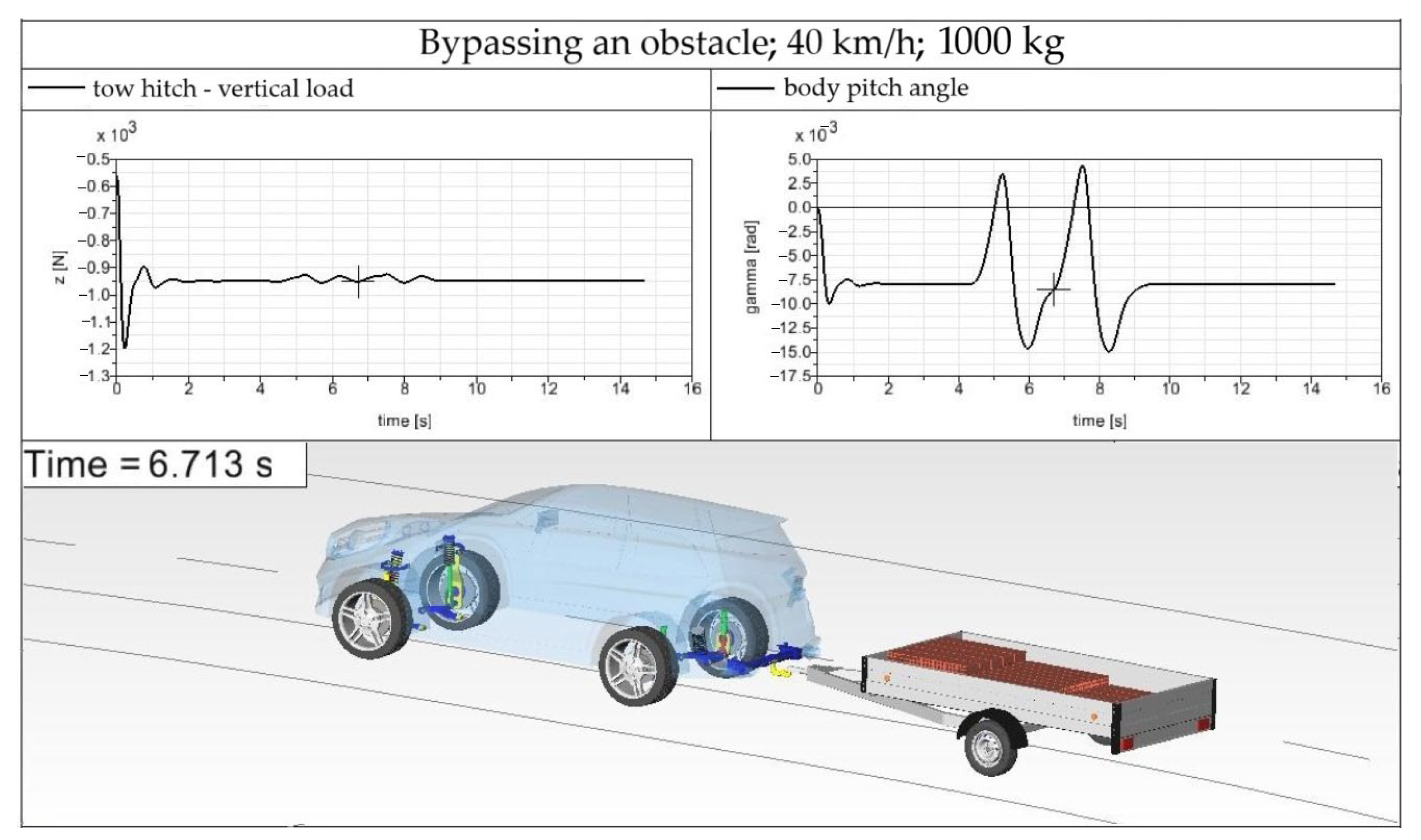
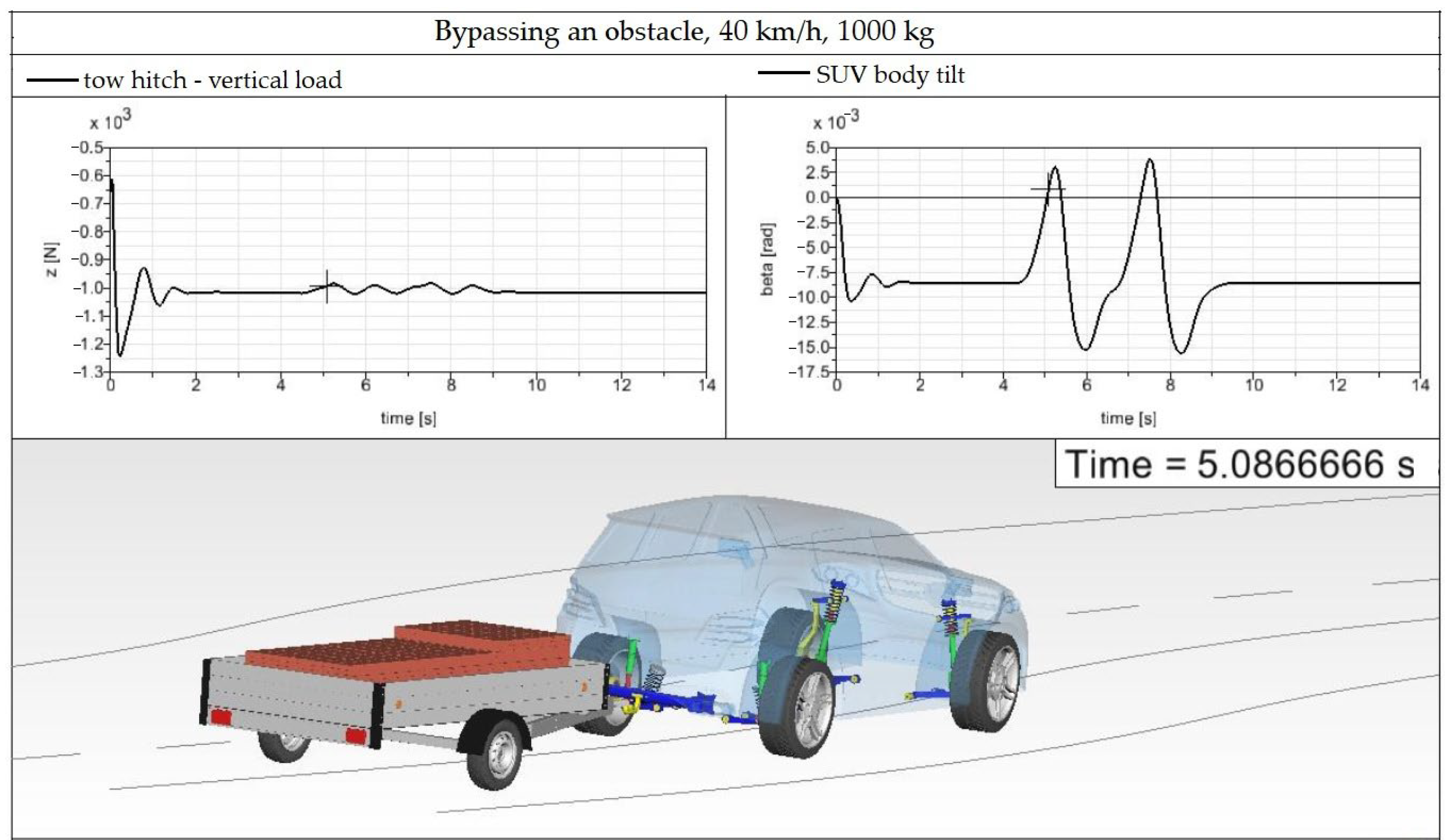
This driving maneuver serving for investigation of the SUV–trailer combination while bypassing an obstacle on a road lane was performed for the driving speed of 40 km/h and the trailer was loaded by the load of 500 kg (a half of the trailer payload). Firstly, the correctness of the load distribution on the trailer loading area is verified. The aim is to find out that the maximal load of the tow hitch in the vertical direction is not exceeded. The driving maneuver is shown in Figure 17.
The left graph in Figure 17 depicts the waveform of the vertical load of the tow hitch. The load is 1000 N in the straight road section as well as in a curve (the load has negative values because it acts in the negative direction of the z-axis, but the absolute value is considered). With the gravitational acceleration of 9.81 m/s2, the value of 1000 N means the vertical load of the tow hitch is 101.937 N. The maximal permissible load of the tow hitch is 140 kg, i.e., 1373.4 N. This means that the tow hitch is not overloaded, and the load is properly distributed on the trailer loading area.
The right graph of Figure 17 shows the body pitch angle of the SUV. It is possible to calculate how the trailer load acts on the SUV body, i.e., to calculate the SUV body inclination. During the steady driving, the SUV body is declined by an angle of 0.008 rad (0.4584°). The declination of the rear part of the SUV body is 12.3 mm. During the bypassing of the road obstacle, the SUV body declines by the value of 23.1 mm.
The SUV–trailer combination bypasses the obstacle safely; no skidding is detected.
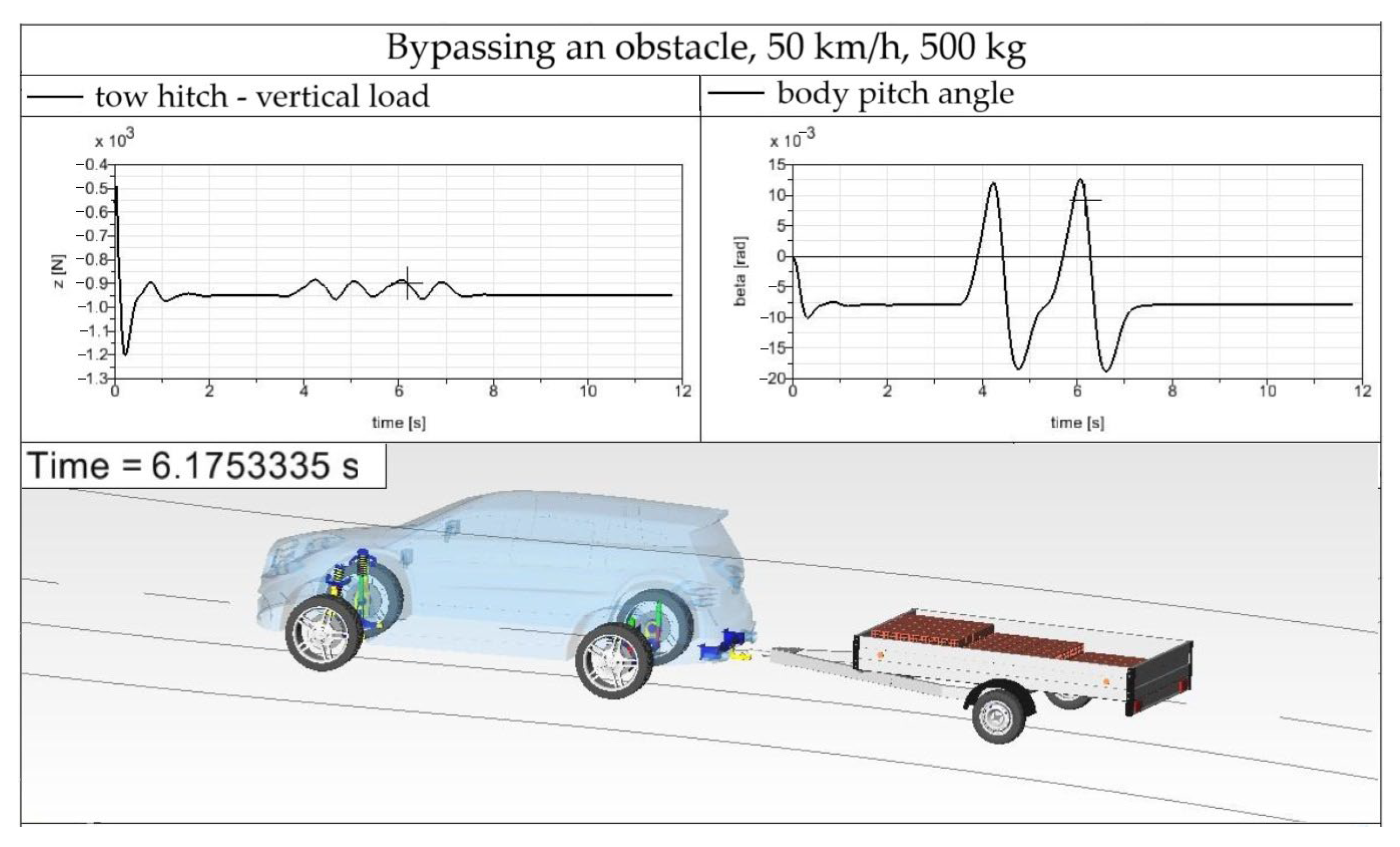
When the SUV–trailer combination drives this maneuver at a driving speed of 50 km/h, the SUV body’s declination is 28.4 mm. The results are shown in Figure 18.
The vertical load of the tow hitch is still the same as in the previous driving speed of 40 km/h. The driving maneuver is safe. The left graph in Figure 18 shows the vertical load of the tow hitch, and the right graph depicts the SUV body pitch for 50 km/h and a trailer load of 500 kg.
When the driving speed is increased to 55 km/h, the evaluated output parameters of the SUV–trailer combination change and are depicted in Figure 19. The maximal vertical load of the tow hitch is still the same as for the driving speeds of 40 km/h and 50 km/h, or it changes only minimally. The driving speed of 55 km/h is evaluated as the limit speed, at which the car-trailer combination bypasses the road obstacle safely. Higher driving speeds cause skidding, as also follows from Figure 19. The body pitch angle has a maximal value of 0.0208 rad, which leads to the body declination of 32 mm. As is common for SUVs and it is caused by their design (a higher position of the center of gravity), the examined SUV car also leans in a curve. The body roll angle of the SUV for the driving speed of 55 km/h is shown in Figure 19. The biggest roll angle of 0.092 rad is detected during bypassing of the road obstacle.
Figure 20 shows the SUV–trailer combination when driving around an obstacle at a speed of 60 km/h to clearly see the behavior of the trailer at a higher driving speed. At this speed, the load acting on the tow hitch, as well as the tilting and leaning of the vehicle, are no longer evaluated. It is already visible at first glance that the trailer is skidding and almost crossing into the other lane. The observation shows that driving the SUV–trailer combination at a speed higher than 55 km/h is dangerous for both the vehicle crew and passing vehicles, as well as all other road users.
After driving maneuvers in which less than half of the trailer’s payload was loaded, the trailer is loaded with 1000 kg, which is the total load of the trailer. The first pallet weight is 400 kg, the second pallet weight is 300 kg and the third pallet weight is of 300 kg. They are loaded with bricks. A illustration of this configuration of the SUV–trailer combination is shown in Figure 21.
The first driving maneuver is performed at a driving speed of 40 km/h for both loads of 500 kg as well as 1000 kg. Graphs and visualization of the vehicle–trailer combination entering a curve with the given load and at a driving speed of 40 km/h are depicted in Figure 22.
The graph of the maximum load acting on the tow hitch shows that pallets with bricks are loaded correctly. The maximum value is at the level of –1244 N. This means that the SUV-car is still pulling the trailer with a reserve. As already explained, this is the value that corresponds to the load at the moment the vehicle–trailer combination lands on the road from the initial, unloaded state. In real life, such a phenomenon does not occur so easily. If pallets with bricks were carelessly loaded onto the trailer (the entire load would be thrown off the forklift), the maximum force acting on the tow hitch could increase at once in 0.23 s of driving, as can be seen in Figure 22. The maximum load value is important when bypassing an obstacle. This value is around –1000 N, which means that the tow hitch is not overloaded.
The body tilting (the right graph in Figure 22) shows that the maximum value of the tilt angle is 0.156 rad, which represents the approach of the body at the level of the rear wheels by 24 mm. Compared to the SUV–trailer combination driving at a speed of 40 km/h with the difference that it was loaded with only 480 kg, this value is almost the same (23.1 mm). The SUV–trailer combination bypassed the obstacle without the slightest problem. There was no excessive roll or tilting, and the vehicle combination did not skid.
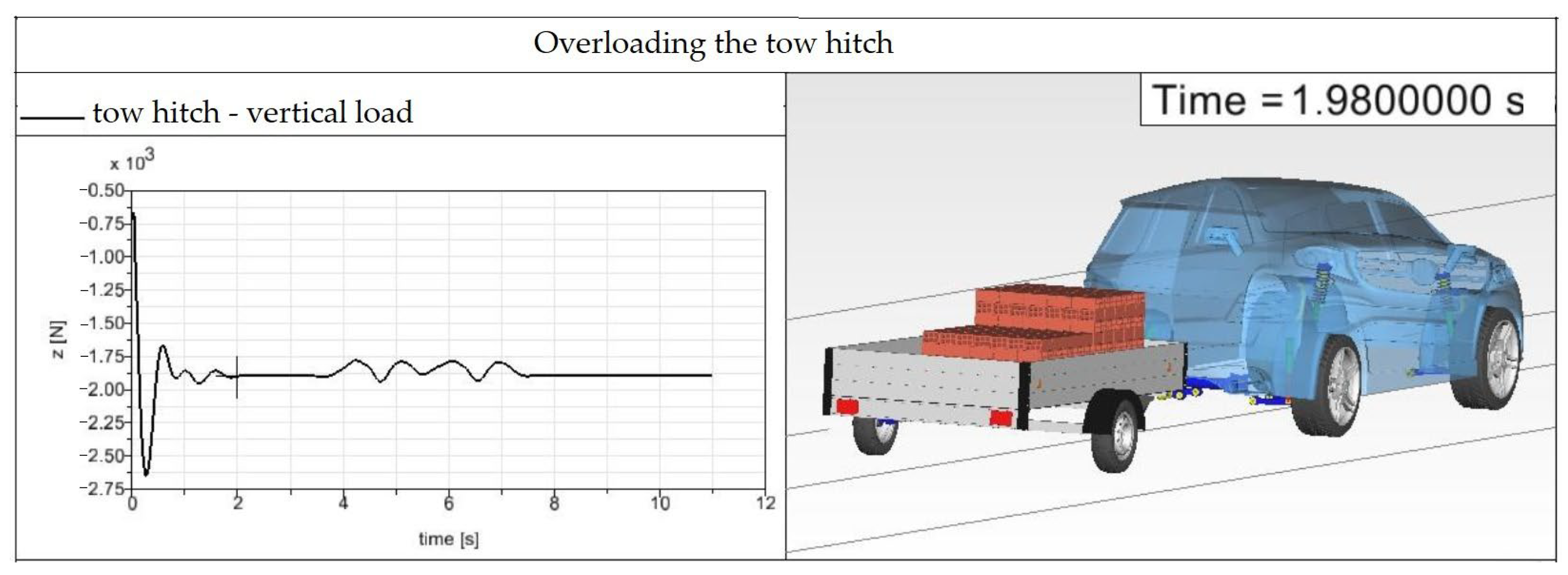
It can be assessed, after investigation of the driving characteristics of the SUV–trailer combination, that in the case of a modelled road which resembles the bypassing a suddenly created obstacle (the shape of the road shown in Figure 20), the weight of the loaded load does not play a role in the characteristics of the combination, but its distribution and the speed of the combination. The following figures and graphs show how an incorrectly loaded load can affect the characteristics of the combination. It is evaluated in terms of both the exceeded maximum load acting on the tow hitch (Figure 23) as well as the loss of control over the vehicle (Figure 24).
In the case of the driving simulation shown in Figure 23, the SUV-car is pulling the trailer with the load of 1000 kg (the first pallet weight is 540 kg, the second pallet weight is 300 kg and the third pallet weight is 160 kg). It is not visible directly on the vehicle–trailer combination that there is an overload. However, the graph of the maximum load of the tow hitch shows that it is excessively overloaded. The load values on the horizontal parts of the graph (values of steady-state driving) are at the level of –1900 N, and when bypassing an obstacle and the vehicle combination touches the road up to –2650 N. These values are unacceptable for the operation of the given vehicle (the maximum permissible load is 1373.4 N).
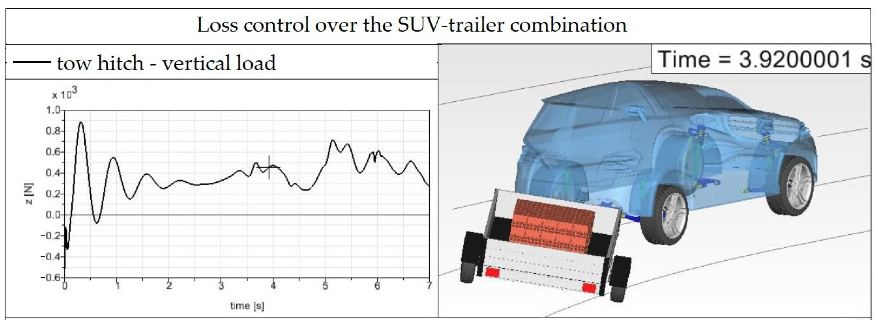
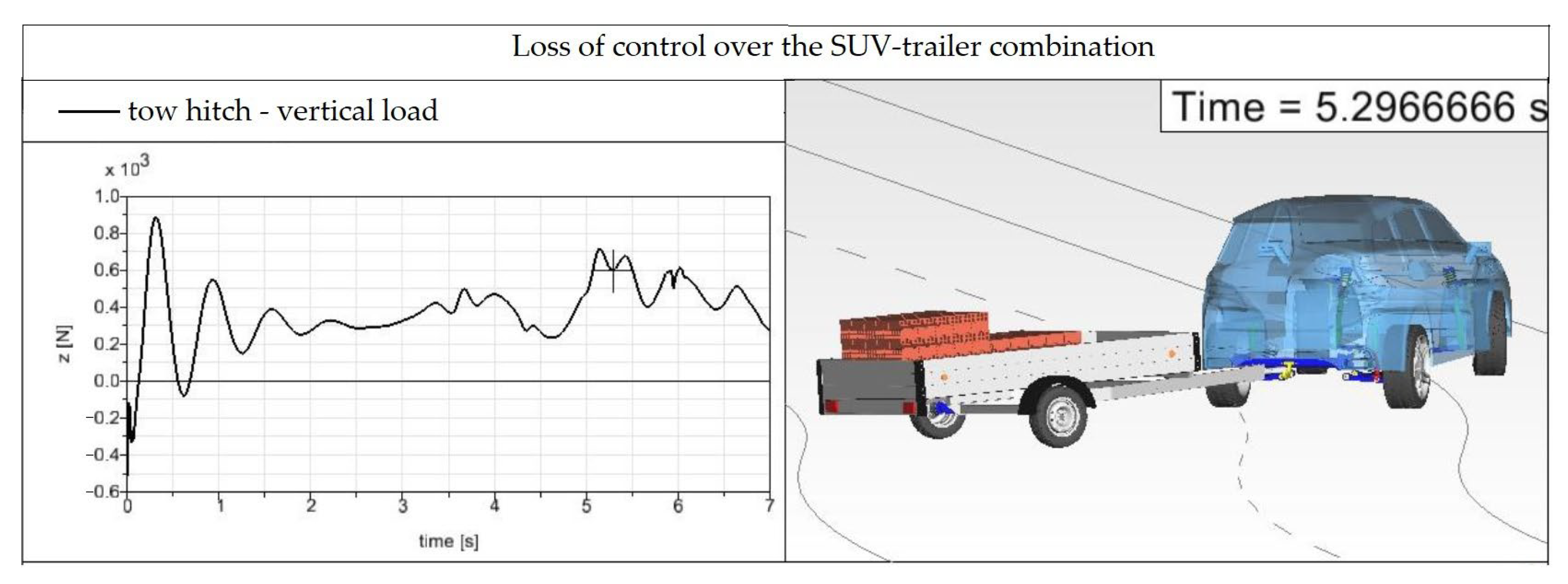
When the pallets are loaded on the trailer mirror-like in the lateral direction in comparison with the loading shown in Figure 23, namely the first pallet weighing 160 kg, the second pallet weighing 300 kg and the third pallet weighing 540 kg of bricks, the stability of the SUV–trailer combination will be lost (Figure 24). The center of gravity of the trailer is in the rear part.
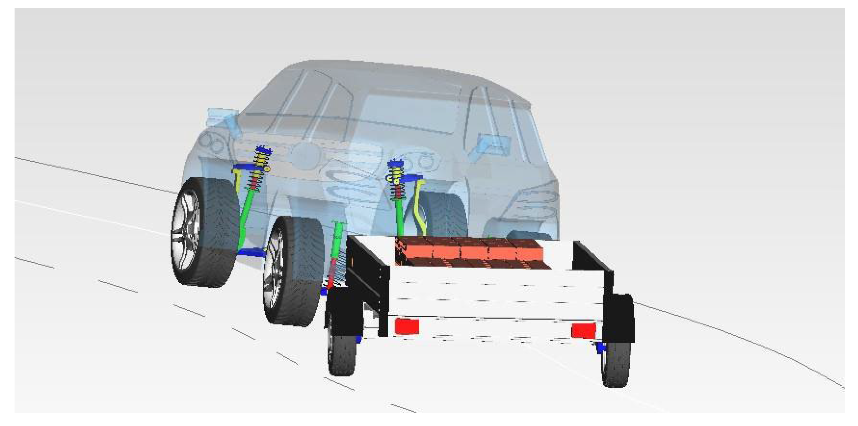
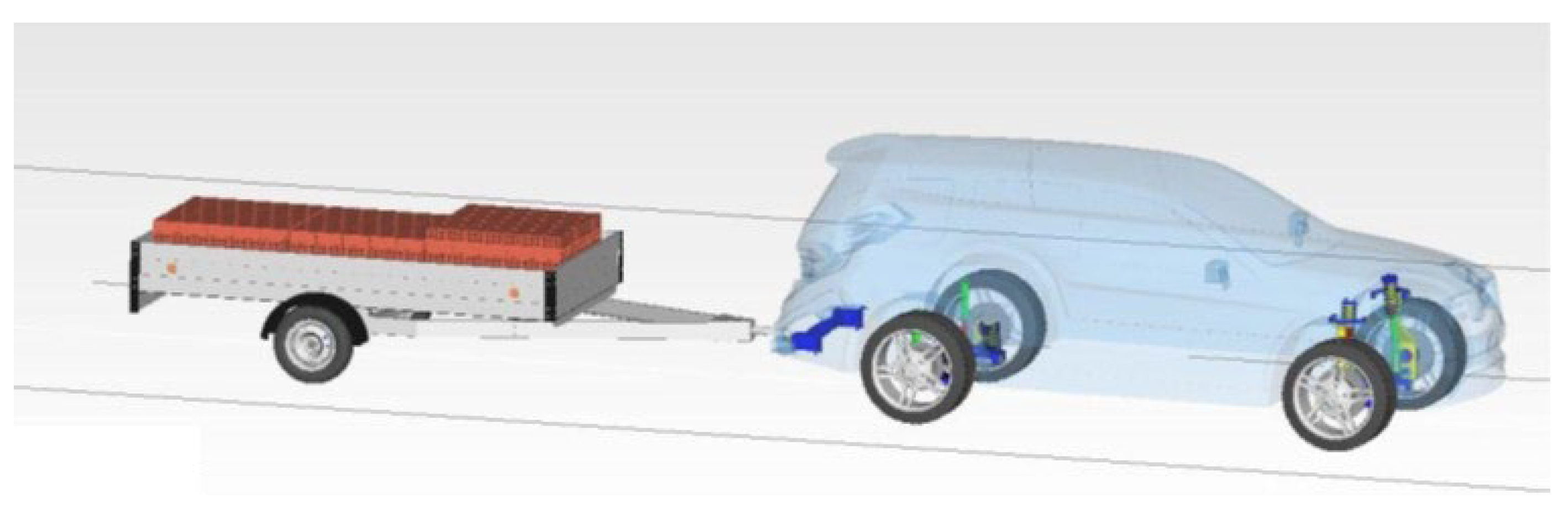
The SUV–trailer combination shown in Figure 24 is located at the transition from the second curve to a five-meter straight section of the road (the geometry of the modeled road is depicted in Figure 16). It can already be seen in Figure 24 that the rear wheel of the trailer goes beyond the roadside due to the excessive turning of the trailer. After passing the 5-m straight section of the road to the next two curves, the vehicle gets into a situation as shown in Figure 25. The trailer gets to the opposite side of the road, and there is a complete loss of control over the SUV–trailer combination. It can be assessed that operating the SUV–trailer combination with such a load distribution would be life-threatening in normal traffic.

4.2. Driving the SUV–Trailer Combination While Changing Lanes—Maneuver B

In addition to bypassing an obstacle on the road, which suddenly appeared and had to be bypassed immediately, it is also dangerous to simply go around a vehicle, or rather to change lanes. Such a situation can appear either on a regular two-lane road or on an expressway/motorway. In this section of the work, the difference between driving at a higher speed when changing lanes and driving at a lower speed when bypassing an obstacle is revealed. As was seen in Section 3.1, bypassing an obstacle with the SUV–trailer combination is dangerous primarily in terms of incorrectly loaded goods on the trailer. As it is already known which load distribution is correct or incorrect for the selected SUV–trailer combination, this section continues with the already used combinations of pallets with bricks. The geometry of the used modeled road is shown in Figure 26. The roadway consists of a straight section, followed by two curves with a radius of 326 m and a curve length of 35 m, which gradually transition into another straight section. For a better understanding of the shape and longitudinal dimensions of the roadway, the basic dimensions are marked in Figure 26.
Verification of the maximum load acting on the tow hitch will no longer be carried out. The previous observation of the behavior of the vehicle–trailer combination (Section 3.1) proved that a correctly distributed load on the trailer does not lead to overloading the tow hitch. The observation also resulted in the fact that the monitored parameters, such as the roll angle and the pitch angle, with the correct load distribution, differ only minimally depending on the load distributed on the trailer (the deviations between the monitored parameters at the same speed and the load of either 500 kg or 1000 kg were insignificant). This observation shows that it is sufficient to consider only one correct load for monitoring the driving characteristics of the SUV–trailer combination when changing lanes. For these driving maneuvers, the load of 1000 kg is chosen.
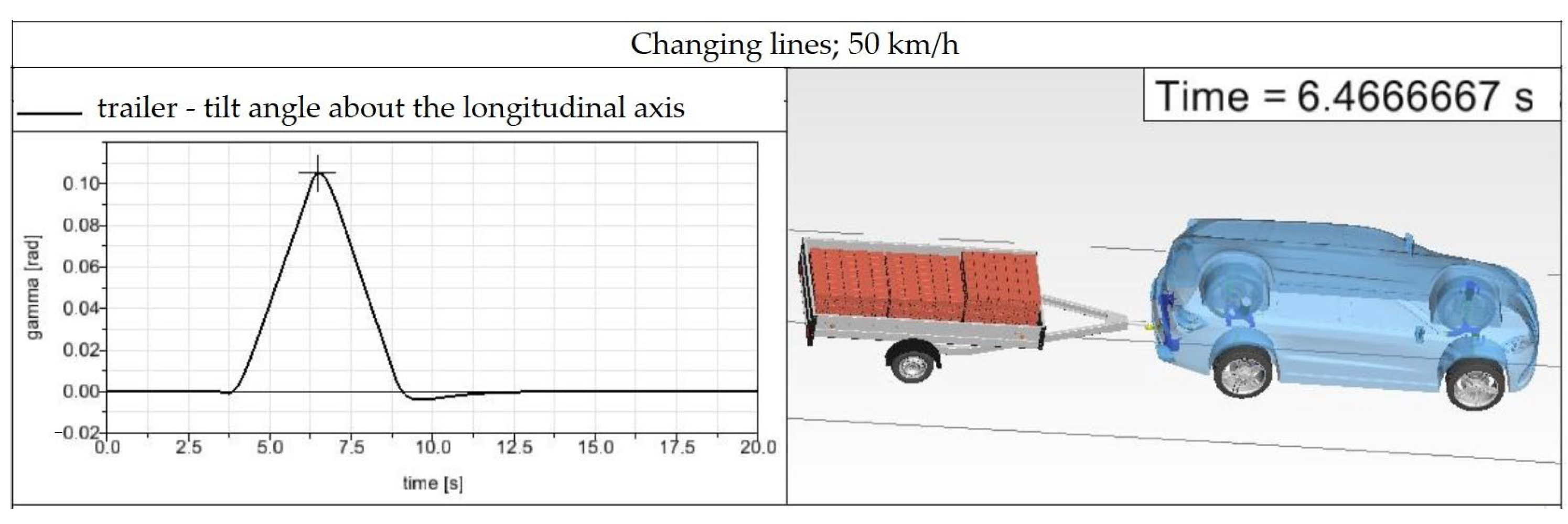
It is also a difference in comparison with Section 3.1 in the evaluated achieved results. The main monitored parameter is the sway of the trailer (a change of the angle of rotation of the trailer around the vertical z-axis, Figure 6). Since the resulting sway angle is evaluated relative to the coordinate axis and not directly to the road, the first step is to create a basic, comparative model with respect to which the turning will be compared (Figure 27). The turning of this model is performed at a driving speed of 50 km/h. Due to the road geometry (curves with a larger radius), the speed of 50 km/h is taken as the driving speed at which the angle of rotation of the trailer changes only due to the shape of the road and not due to undesirable influences such as loss of traction between the tires of the trailer and the road.
The maximum yaw angle of the trailer is 0.1053 rad, which corresponds to the value of 6.033°. As mentioned above, this angle results from the characteristics of the road.
In addition to the difference in the evaluated quantities, there is also a difference in the observed speeds. The following three driving cases of the Maneuver B were observed in the simulations:
  • Case 4: 80 km/h—the lowest permitted driving speed on a motorway/expressway, unless the road goes through a village;
  • Case 5: 110 km/h—the normal driving speed on a motorway if the driver is aware that he is not only driving the vehicle, but also has the load in a trailer;
  • Case 6: 130 km/h—the maximum permitted driving speed on a motorway/expressway and also the maximum design speed of a trailer.
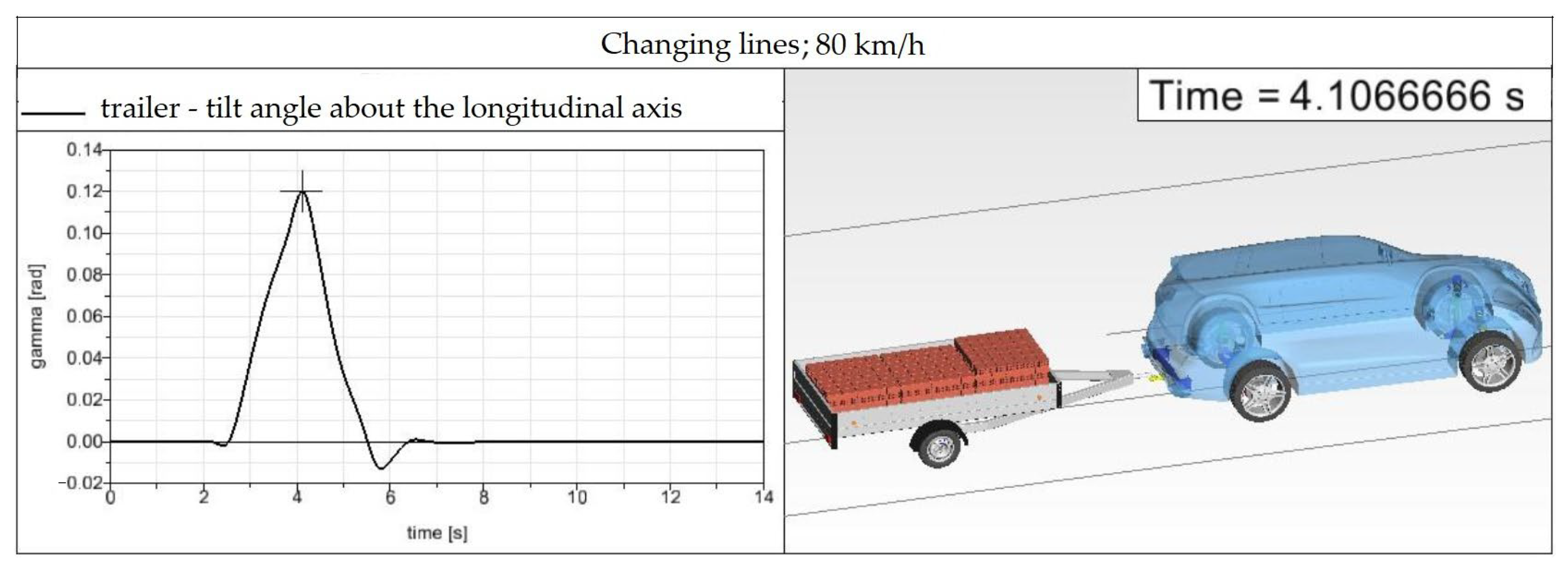
If the SUV–trailer combination drives along the modeled road at the driving speed of 80 km/h (Figure 28), the yaw angle values differ slightly from the basic model (Figure 27). The maximum yaw angle value is at the level of 0.12 rad (6.87°), which implies that this speed is safe for driving and does not cause any undesirable effects.
After increasing the driving speed to the value of 110 km/h, the trailer’s yaw rate increases (0.1539 rad = 8.818°), and a slight tilt of the trailer also occurs. The increase in yaw is caused by the higher driving speed, but this value does not have a negative effect on the SUV–trailer combination. In the case of a real vehicle combination, the trailer’s tilt could be a bigger problem, especially when a larger amount of goods is loaded, or cargo with a higher weight. In addition to the higher weight, the behavior of the vehicle–trailer combination could also be affected by loading cargo with a higher center of gravity, and improper securing of the cargo, which could loosen due to centrifugal force in a bend and change the overall behavior of the vehicle combination.
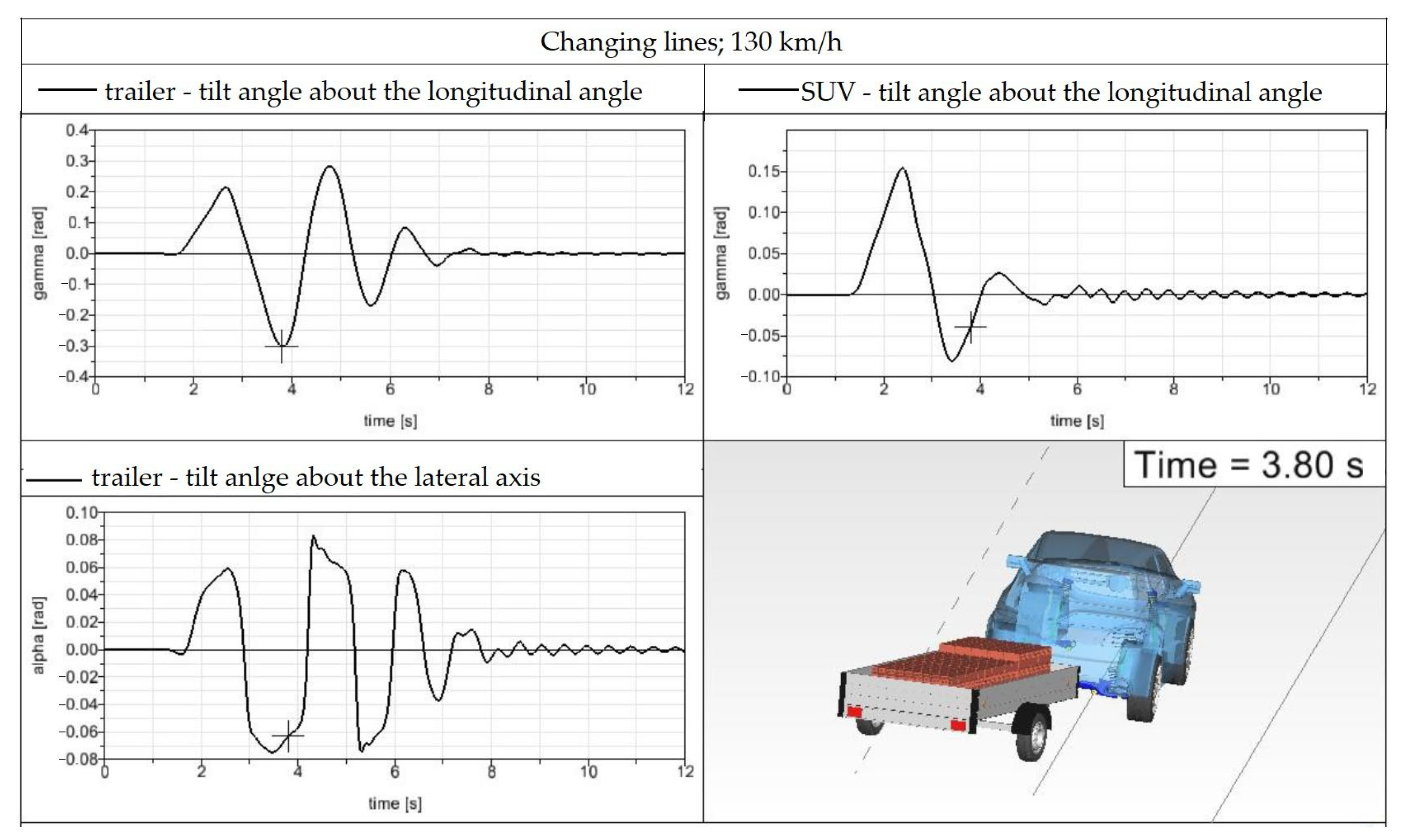
A big difference compared to the basic model can be observed at a speed of 130 km/h. The turning of the trailer reaches almost three-times-higher values, up to 0.301 rad (17.246°), which clearly shows that such a high speed is unacceptable for the investigated SUV–trailer combination. At the driving speed of 130 km/h, traction is lost between the trailer tires and the road, and the trailer starts to skid (Figure 29).
In addition to the turning of the trailer, its roll is also significant at the driving speed studied (a graph on the bottom left of Figure 29). The maximum roll value of 0.0832 rad reaches the level of the trailer wheels, the fenders approaching the wheels by 84.7 mm compared to the equilibrium state.
A special phenomenon can be observed when the vehicle is turning (a graph on the top right of Figure 29). What is interesting is not so much the maximum vehicle roll (0.1536 rad = 8.8°), but the vehicle behavior from the 4th second to the end of the simulation. Both the vehicle and the trailer oscillate around the z-axis due to the excitation caused by driving through a curve at high speed. This oscillation does not stabilize even after driving a straight section of the road with a length of 350 m. It can be assessed in the case of driving at the driving speed of 130 km/h, that the operation of the vehicle combination with the used load is not permissible for safe driving.

4.3. Discussion of the Resutls

The performed simulation computation with the chosen SUV–trailer combination proved that its driving properties represent a quite complicated phenomenon affected by several factors.
The position of the center of gravity of the trailer can be considered as the first and the most important factor. Its influence on the vehicle–trailer combination driving stability is such that the trailer with the center of gravity positioned behind the trailer axis is very prone to unstable movement. Only a small excitation force is needed, and the vehicle becomes uncontrollable relatively quickly (in a short time).
It is necessary to consider the weight of the trailer itself. A higher weight of the trailer in combination with an improper position of the center of gravity results in unstable movement the entire vehicle–trailer combination [42,43,44,45].
Driving speed is another factor, which affects the stability of the vehicle–trailer combination during driving. The vehicle–trailer combination is more sensitive to the load distribution at higher driving speeds. At the higher driving speed of the vehicle, only a small excitation force is sufficient to cause uncontrolled movement the vehicle–trailer combination, mainly when the above-described conditions are met. The achieved results of the assessed criteria listed in Table 1 are summarized in Table 7 for all six driving cases.
Regarding driving Maneuver A, driving with the load of 1000 kg at the speed of 40 km/h (the driving Case 1) as well as with the load of 500 kg and speed of 50 km/h (the driving Case 2) does not lead to exceeding the limit value of 3.924 m/s2. When the angle ψ is evaluated, it is also below the limit value of 15° for driving cases 1 and 2. However, driving the SUV–trailer combination with the load of 500 kg at the speed of 55 km/h (the driving Case 3) causes exceeding the limit value of the lateral acceleration as well as the ψ angle. The lateral acceleration is exceeded by 2.096 m/s2 and the limit value of the ψ angle by 1.86°. These findings were manifested by unstable driving of the SUV–trailer combination, as is discussed below.
The given criteria evaluated for driving Maneuver B (driving the SUV–trailer combination while changing lanes) are also included in Table 7. Driving at the speed of 80 km/h (the driving Case 4) and at the speed of 100 km/h (driving Case 5) resulted in lateral accelerations of 1.76 m/s2 and 2.87 m/s2, respectively. Both values are lower than the limit value of 3.924 m/s2. The evaluated ψ angle was, for the driving speeds of 80 km/h and 110 km/h, under the limit value of 15°. The achieved values were 6.87° and 8.83°, respectively. However, driving the SUV–trailer combination at the speed of 130 km/h (the driving Case 6) was already unstable. This is manifested by the achieved value of the lateral acceleration of 6.04 m/s2, which is higher by 2.116 m/s2 than the limit value of 3.924 m/s2 and also by the achieved value of the ψ angle, which is higher by 2.27° than the limit value of 15°. This unstable state is also discussed below.
Further, it is possible to express other dependencies of the stability of the vehicle–trailer combination on other factors. An incorrect tow hitch load has negative effects on driving stability. When the tow hitch is loaded with too high a weight, the vehicle–trailer combination has the tendency to preserve a straight direction in a curve [46,47,48]. Too small a weight on the tow hitch has a destabilizing effect, as was investigated and presented above. Next, the tire pressure is inconspicuous but is an important factor affecting the driving stability of the vehicle–trailer combination. It is required to keep the tire air pressure within the prescribed range by the vehicle producer. It is also possible to suppose that weather conditions can affect the safe driving of the vehicle–trailer combination. A slippery road together with sudden changes of driving direction negatively influences the stability of the movement [49]. Moreover, it was found that driving a vehicle over speed bumps has negative dynamic impacts on the vehicle structure, the passengers in a vehicle as well as the trailer [50,51,52]. In the case of the examined single-axle trailer, rubber deformable components are installed as a suspension between the swinging arms of the axle and the main load-bearing beam of the axle. These elements are dimensioned for the high load of the trailer. Therefore, the empty state of the trailer leads to high vertical displacements and even to loss of tire/road contact. This will also be investigated in future research activities with the vehicle–trailer combination [31].

5. Conclusions

The research was focused on the investigation of the driving stability of the vehicle–trailer combination for chosen driving maneuvers. The study was based on simulation computations in the commercial multibody simulation software Simpack. An SUV–trailer combination was chosen for research. Two driving maneuvers were selected for the research, namely bypassing an obstacle on the road and changing the lane on the road. The main goal was to find out which position of the load, i.e., the center of gravity of the trailer, is more favorable for driving safety. Alongside this, the movement of the SUV–trailer combination was examined for various loads and driving speeds were examined.
The SUV–trailer combination was analyzed for two driving maneuvers with the following results:
  • Maneuver A: bypassing an obstacle in a lane: the load of 1000 kg at the driving speed of 40 km/h led to the vertical load of the tow hitch of 102 N (after rounding). The SUV–vehicle bodywork tilting angle was of 0.008 rad (0.4584°), which is 12.3 mm. Further, the driving speed of 50 km/h caused the slightly higher value of the SUV–vehicle bodywork of 23.1 mm. The driving speed of 55 km/h was the safe driving speed limit, wherein the SUV–trailer combination can drive and maneuver safely. The driving speed higher than 55 km/h led to dangerous, unstable movement of the examined SUV–trailer combination.
  • Maneuver B: changing lanes: three driving speeds were examined regarding driving safety, namely 80 km/h, 110 km/h and 130 km/h. The tilting angle of the SUV–vehicle at the driving speed of 80 km/h was of 6.87 and at the driving speed of 110 km/h was of 8.813°. The driving of the SUV–trailer combination was safe for both driving speeds. Finally, the driving was analyzed for the speed of 130 km/h. It was discovered that this running speed caused the loss of stability of the SUV–trailer combination (maximal tilting angle was of 17.246°), and this driving speed was dangerous for the examined SUV–trailer combination.
The driving properties of the SUV–trailer combination were also evaluated by means of the given limit values of lateral acceleration ay, the yaw instability angle ψ and the deviation of the angle Δφ. The achieved results of the simulation computations for all driving cases showed that driving Maneuver A leads to unstable behavior at the load of 500 kg and speed of 55 km/h, because the lateral acceleration ay achieved the maximal value of 6.02 m/s2 and yaw angle ψ achieved the value of 16.86°. Further, driving Maneuver B causes unstable driving behavior of the analyzed SUV–trailer combination at the speed of 130 km/h, as the lateral acceleration ay was 6.04 m/s2 and the yaw angle ψ was 17.27°.
The performed research confirmed facts about the driving stability of the vehicle–trailer combination, and it also brought new results. These new results revealed the speed limits, the position of the center of gravity and the load value of the particular vehicles (the SUV, the trailer) at which driving stability is no longer ensured.
The future research in this field will be focused on the investigation of other driving maneuvers. It is supposed that driving over a road obstacle will be assessed by means of the created SUV–trailer combination model. It will simulate driving over a speed bump, as this road obstacle leads to the adverse dynamic loads of the vehicle as well as the trailer. The authors’ team is considering comparing achieved results from simulations with experiments with a real vehicle–trailer combination. Such research will be useful to reveal correctness and limits of simulations and a simulation model. Furthermore, the implementation of a flexible body to the multibody model of the SUV–trailer combination will contribute to a more realistic model. This will be applied mainly to the single-axle trailer model due to available geometry.

Author Contributions

Conceptualization, J.D., M.B. and A.L.; methodology, J.D. and J.M.; software, J.D. and A.L.; validation, M.B. and J.M.; formal analysis, J.D. and A.L.; investigation, M.B. and J.M.; resources, J.D. and A.L.; data curation, J.D., M.B. and A.L.; writing—original draft preparation, J.D. and A.L.; writing—review and editing, M.B. and J.M.; visualization, J.D.; project administration, J.D. and A.L.; funding acquisition, J.D., M.B. and A.L. All authors have read and agreed to the published version of the manuscript.

Funding

This research was supported by the Slovak Research and Development Agency of the Ministry of Education, Science, Research and Sport of the Slovak Republic VEGA 1/0037/25 “Research of the Properties of the Structural Design of a New Type of Unconventional Mechanism Implementable in Light Road Vehicles with a Self-locking Effect when the Torque Differential of the Driving Axle Wheels is Required”. This publication was also supported by the Cultural and Educational Grant Agency of the Ministry of Education of the Slovak Republic under project KEGA 024ZU-4/2024 (“Deepening the Knowledge of University Students in the Field of Construction of Means of Transport by Carrying Out Professional and Scientific Research Activities in the Field”). It was also “Funded by the EU NextGenerationEU through the Recovery and Resilience Plan for Slovakia under the project No. 09I03-03-V01-00131.”.

Institutional Review Board Statement

Not applicable.

Informed Consent Statement

Not applicable.

Data Availability Statement

The original contributions presented in the study are included in the article, further inquiries can be directed to the corresponding author.

Acknowledgments

The authors’ team acknowledges to Ing. Michal Suchý for help with creating the model and performing simulation analyses.

Conflicts of Interest

The authors declare no conflicts of interest.

References

  1. Hung, T.T. Analysis and Evaluation of Roll Safety Thresholds of Tractor Semi-Trailer Vehicles during Turning Maneuvers Based on the Yaw Rate of Vehicle Bodies and Roll Safety Factor. SAE Int. J. Commer. Veh. 2025, 18, 1–17. [Google Scholar] [CrossRef]
  2. Caban, J.; Nieoczym, A.; Matijošius, J.; Kilikevičius, A.; Drozd, K. Analysis of the construction of the car trailer frame in terms of changing the assembly technology. Sci. J. Silesian Univ. Technol. Ser. Transp. 2024, 124, 47–61. [Google Scholar] [CrossRef]
  3. Decker, Ž.; Rudzinskas, V.; Drozd, K.; Caban, J.; Tretjakovas, J.; Nieoczym, A.; Matijošius, J. Analysis of the Vehicle Chassis Axle Fractures. Materials 2023, 16, 806. [Google Scholar] [CrossRef] [PubMed]
  4. Lyashuk, O.; Levkovych, M.; Vovk, Y.; Gevko, I.; Stashkiv, M.; Slobodian, L.; Pyndus, Y. The study of stress-strain state elements of the truck semi-trailer body bottom. Sci. J. Silesian Univ. Technol. Ser. Transp. 2023, 118, 161–172. [Google Scholar] [CrossRef]
  5. Ulewicz, R.; Mazur, M. Economic aspects of robotization of production processes by example of a car semi-trailers manufacturer. Manuf. Technol. 2019, 19, 1054–1059. [Google Scholar] [CrossRef]
  6. Szalai, S.; Herold, B.; Kurhan, D.; Németh, A.; Sysyn, M.; Fischer, S. Optimization of 3D printed rapid prototype deep drawing tools for automotive and railway sheet material testing. Infrastructures 2023, 8, 43. [Google Scholar] [CrossRef]
  7. Rafat, M.; Azadi, S. A Novel Flexible Lane Changing (FLC) Method in Complicated Dynamic Environment for Automated Vehicles. J. Appl. Comput. Mech. 2023, 9, 318–331. [Google Scholar] [CrossRef]
  8. De Bernardis, M.; Rini, G.; Bottiglione, F.; Hartavi, A.E.; Sorniotti, A. On nonlinear model predictive direct yaw moment control for trailer sway mitigation. Veh. Syst. Dyn. 2022, 61, 445–471. [Google Scholar] [CrossRef]
  9. Trailer Sway—How Not to Fix, and How to Fix. Available online: https://www.youtube.com/watch?v=nc0ndz92IWY (accessed on 2 March 2025).
  10. ISO 4138, 2021; Passenger Cars—Steady-State Circular Driving Behaviour—Open-Loop Text Methods. International Organization for Standardization: Geneva, Switzerland, 2021.
  11. Forkenbrock, G.J.; Elsasser, D.; O’Harra, B. NTHSA’s Light Vehicle Handing and ESC Effectiveness Research Program; National Highway Traffic Safety Administration: Washington, DC, USA, 2005. [Google Scholar]
  12. Nusholtz, G.S.; Kaiker, P.S.; Muscott, G.J.; Suggitt, B.R. UMTRI Experimental Techniques in Head Injury Research. SAE Trans. 1985, 94, 88–96. [Google Scholar]
  13. Robat, A.B.; Arezoo, K.; Alipour, K.; Tarvirdizadeh, B. Dynamics modeling and path following controller of tractor-trailer-wheeled robots considering wheels slip. ISA Trans. 2024, 148, 45–63. [Google Scholar] [CrossRef]
  14. Harlecki, A.; Przemyk, A.; Tengler, S. Application of Homogenous Transformations in the Dynamic Analysis of Truck Trailers. In Perspectives in Dynamical Systems I: Mechatronics and Life Sciences, 1st ed.; Awrejcewicz, J., Ed.; Springer: Cham, Switzerland, 2019; Volume 362, pp. 159–170. [Google Scholar] [CrossRef]
  15. Ta, T.H.; Vo, V.H.; Duong, N.K. Study on the Dynamic Rollover Indicators of Tractor Semi-trailer Vehicle While Turning Maneuvers Based on Multibody System Dynamics Analysis and Newton-Euler Equations. In Proceedings of the International Conference on Advanced Mechanical Engineering, Automation and Sustainable Development, 1st ed.; Long, B., Kim, H.S., Ishizaki, K., Toan, N.D., Parinov, I.A., Kim, Y.-H., Eds.; Springer: Cham, Switzerland, 2022; Volume 3, pp. 30–38. [Google Scholar] [CrossRef]
  16. Zhang, N.; Zhang, Q.; Zhao, Z.; Yin, G.; Li, S.; Lu, H.; Wang, C. A Phase Portrait-Based Sliding Mode Control Method to Improve Dynamic Stability of Car-Trailer Combinations via Differential Braking. IEEE Trans. Intell. Transp. Syst. 2025, 1–11. [Google Scholar] [CrossRef]
  17. Zhang, H.; Nie, Z.; Lian, Y. A Semi-Trailer Path Planning Method Considering the Surrounding Traffic Conditions and Vehicle Roll Stability. Appl. Sci. 2025, 15, 2353. [Google Scholar] [CrossRef]
  18. Wang, Z.; Zhang, N.; Zhang, Q.; Jiang, S. Effect of trailer suspension damping tuning on rearward amplification of car-trailer combinations. In Proceedings of the 2023 7th CAA International Conference on Vehicular Control and Intelligence (CVCI), Changsha, China, 27–29 October 2023. [Google Scholar] [CrossRef]
  19. Molnár, B.; Kun, K. Advanced Analysis of Wheel Contact Forces in Dual-Unit Vehicles Using Kistler RoaDyn Sensors. Eng. Proc. 2024, 79, 37. [Google Scholar] [CrossRef]
  20. Rini, G.; Mazzilli, V.; Bottiglione, F.; Gruber, P.; Dhaens, M.; Sorniotti, A. On Nonlinear Model Predictive Vehicle Dynamics Control for Multi-Actuated Car-Semitrailer Configurations. IEEE Access 2024, 12, 165928–165947. [Google Scholar] [CrossRef]
  21. Viganico, C.E.H.; Drehmer, L.R.C.; Casas, W.J.P. Safety assessment of a tractor semi-trailer based on handling and stability maneuvers. Proc. Inst. Mech. Eng. Part D J. Automob. Eng. 2025, 09544070251355301. [Google Scholar] [CrossRef]
  22. Oh, J.; Choi, S.O. Optimal tongue weight selection criteria for light vehicle-trailer combinations. Veh. Syst. Dyn. 2024, 1–24. [Google Scholar] [CrossRef]
  23. Viadero-Monasterio, F.; Nguyen, A.-T.; Lauber, J.; Boada, M.J.L.; Boada, B.L. Event-Triggered Robust Path Tracking Control Considering Roll Stability Under Network-Induced Delays for Autonomous Vehicles. IEEE Trans. Intell. Transp. Syst. 2023, 24, 14743–14756. [Google Scholar] [CrossRef]
  24. Viadero-Monasterio, F.; Meléndez-Useros, M.; Zhang, N.; Zhang, H.; Boada, B.L.; Boada, M.J.L. Motion Planning and Robust Output-Feedback Trajectory Tracking Control for Multiple Intelligent and Connected Vehicles in Unsignalized Intersections. IEEE Trans. Veh. Technol. 2025, 1–13. [Google Scholar] [CrossRef]
  25. Viadero-Monasterio, F.; Melendez-Useros, M.; Jimenez-Salas, M.; Lopez Boada, B.; Lopez Boada, M.J. What are the most influential factors in a vehicle platoon? In Proceedings of the IEEE Conference on Evolving and Adaptive Intelligent Systems 2024, Madrid, Spain, 23–24 May 2024. [CrossRef]
  26. Viadero-Monasterio, F.; Meléndez-Useros, M.; Jiménez-Salas, M.; Boada, M.J.L. Fault-Tolerant Robust Output-Feedback Control of a Vehicle Platoon Considering Measurement Noise and Road Disturbances. Iet Intell. Transp. Syst. 2025, 19, e70007. [Google Scholar] [CrossRef]
  27. Viadero-Monasterio, F.; García, J.; Meléndez-Useros, M.; Jiménez-Salas, M.; Boada, B.L.; López Boada, M.J. Simultaneous Estimation of Vehicle Sideslip and Roll Angles Using an Event-Triggered-Based IoT Architecture. Machines 2024, 12, 53. [Google Scholar] [CrossRef]
  28. Tongue Weight Safety Demonstration. Available online: https://www.youtube.com/watch?v=w9Dgxe584Ss (accessed on 25 August 2025).
  29. Dangers of Improper Tongue Weight. Available online: https://www.youtube.com/watch?v=06_lbECEqSg (accessed on 9 September 2025).
  30. Towing a Trailer Can be Dangerous with the Wrong Weight Distribution. Available online: https://www.youtube.com/watch?v=6mW_gzdh6to (accessed on 10 September 2025).
  31. Barta, D.; Blatnický, M.; Lovska, A.; Kowalski, S.; Slíva, A.; Dižo, J. Dynamic Responses of a Single-Axle Trailer When Driving Over a Road Obstacle. Sensors 2025, 25, 5246. [Google Scholar] [CrossRef] [PubMed]
  32. Lovska, A.; Gerlici, J.; Dižo, J.; Ishchuk, V. The Strength of Rail Vehicles Transported by a Ferry Considering the Influence of Sea Waves on Its Hull. Sensors 2024, 24, 183. [Google Scholar] [CrossRef]
  33. Gerlici, J.; Lovska, A.; Vatulia, G.; Pavliuchenkov, M.; Kravchenko, O.; Solcanský, S. Situational Adaptation of the Open Wagon Body to Container Transportation. Appl. Sci. 2023, 13, 8605. [Google Scholar] [CrossRef]
  34. Dižo, J.; Blatnický, M.; Droździel, P.; Melnik, R.; Caban, J.; Kafrik, A. Investigation of Driving Stability of a Vehicle–Trailer Combination Depending on the Load’s Position Within the Trailer. Acta Mech. Autom. 2023, 17, 60–67. [Google Scholar] [CrossRef]
  35. Sakhno, V.; Murovanyi, I.; Razboinikov, O.; Palamarchyk, O.; Dembitskyi, V. Comparative Estimation of Maneuverability of the Multi-Track Road Trains of Different Layout Schemes. Commun. Sci. Lett. Univ. Zilina 2025, 27, B30–B40. [Google Scholar] [CrossRef]
  36. Sokil, B.; Lyashuk, O.; Sokil, M.; Vovk, Y.; Lebid, I.; Hevko, I.; Levkovych, M.; Khoroshun, R.; Matviyishyn, A. Methodology of Force Parameters Justification of the Controlled Steering Wheel Suspension. Commun. Sci. Lett. Univ. Zilina 2022, 24, B247–B258. [Google Scholar] [CrossRef]
  37. Charles, T.; Yang, Z.; Lu, Y. Assessment of Drag Reduction Devices Mounted on a Simplified Tractor-Trailer Truck Model. J. Appl. Comput. Mech. 2021, 7, 45–53. [Google Scholar] [CrossRef]
  38. Manrique-Escobar, C.A.; Pappalardo, C.M.; Guida, D. On the Analytical and Computational Methodologies for Modelling Two-wheeled Vehicles within the Multibody Dynamics Framework: A Systematic Literature Review. J. Appl. Comput. Mech. 2022, 8, 153–181. [Google Scholar] [CrossRef]
  39. Vlk, F. Dynamics of Engine Vehicles; Frantisek Vlk Publishing Hause: Brno, Czechia, 2003. (In Czech) [Google Scholar]
  40. Pacejka, H. Modeling of the Tyre as a Vehicle Component with Applications; CCG-Course V2.01; Carl-Cranz-Gesellschaft: Weßling, Germany, 1982. [Google Scholar]
  41. ISO 3888-2:2011; Passenger Cars—Test Track for a Severe Lane-Change Manoeuvre. International Organization for Standardization: Geneva, Switzerland, 2011.
  42. Marchuk, R.; Sakhno, V.; Chovcha, I.; Marchuk, N.; Marchuk, M. To determine stability of the road train with O1-category trailer. Scientific Journal of Silesian University of Technology. Ser. Transport. 2023, 119, 159–170. [Google Scholar] [CrossRef]
  43. Žuraulis, V.; Sokolovskij, E.; Matijošius, J. The opportunities for establishing the critical speed of the vehicle on research in its lateral dynamics. Eksploat. Niezawodn. Maint. Reliab. 2013, 15, 312–318. [Google Scholar]
  44. Beresnevich, V.; Viba, J.; Kovals, E.; Irbe, M.; Eiduks, M. Lateral sway motion of vehicle and trailer. In Proceedings of the Engineering for Rural Development 2024, Jelgava, Latvia, 22–24 May 2024; pp. 344–350. [Google Scholar] [CrossRef]
  45. Mengdi, L.; Li, D.; Fu, Q.; Yang, Z.; Wang, W. The influence of tongue weight of a trailer-mounted recreational vehicle on steering stability. J. Theor. Appl. Mech. 2021, 59, 203–213. [Google Scholar] [CrossRef]
  46. Zerbato, L.; Galvagno, E.; Tota, A.; Velardocchia, M. Car-Trailer Dynamics: Modelling for Parametric Study on System Stability. Mech. Mach. Sci. 2022, 122, 422–429. [Google Scholar] [CrossRef]
  47. Sakhno, V.; Polyakov, V.; Murovany, I.; Sharai, S.; Lyashuk, O.; Plekan, U.; Tson, O.; Sokol, M. Stability of the Two-Link Metrobus. Commun. Sci. Lett. Univ. Zilina 2023, 25, B77–B85. [Google Scholar] [CrossRef]
  48. Sharma, T.; He, Y. On Trade-Off Relationship between Static and Dynamic Lateral Stabilities of Articulated Heavy Vehicles. Designs 2024, 8, 103. [Google Scholar] [CrossRef]
  49. Jilek, P.; Berg, J. The adhesion force change of an experimental road vehicle. Manuf. Technol. 2021, 21, 634–639. [Google Scholar] [CrossRef]
  50. Frej, D.P.; Zuska, A.; Cadge, K. Analysis of vertical vibrations affecting a child transported in a child seat during a car passing over the release speed bump. Arch. Automot. Eng. 2019, 86, 111–125. [Google Scholar] [CrossRef]
  51. Zuska, A.; Frej, D.; Jackowski, J.; Żmuda, M. Research and analysis of the propagation of vertical vibrations in the arrangement of a vehicle seat—A child’s seat. Sensors 2021, 21, 8230. [Google Scholar] [CrossRef]
  52. Frej, D.; Grabski, P.; Jurecki, R.S.; Szumska, E.M. Experimental study on longitudinal acceleration of urban buses and coaches in different road maneuvers. Sensors 2023, 23, 3125. [Google Scholar] [CrossRef]
Figure 1. An illustration of a road accident caused due to uncontrolled sway motion of an SUV–trailer combination [9].
Applsci 15 11918 g001
Figure 2. Unstable moving of the vehicle–trailer combination due to gravitational force of the trailer in the rear part [28].
Applsci 15 11918 g002
Figure 3. Stable moving of the vehicle–trailer combination due to gravitational force of the trailer in the front part [28].
Applsci 15 11918 g003
Figure 4. Basic angular movements of the vehicle in space. Note: the negative numerical values presented below mean their downwards orientation in the coordinate system.
Applsci 15 11918 g004
Figure 5. An illustration of the analyzed SUV car.
Applsci 15 11918 g005
Figure 6. An MBS model of the examined SUV car created in the Simpack software, version 2024.3.
Applsci 15 11918 g006
Figure 7. A detailed view of the created MBS model: (a) The front axle of the SUV car; (b) The rear axle of the SUV car.
Applsci 15 11918 g007
Figure 8. An illustration of the analyzed single-axle trailer.
Applsci 15 11918 g008
Figure 9. The multibody model of the trailer: (a) The overall view; (b) The detail of the axle swinging arm.
Applsci 15 11918 g009
Figure 10. The entire SUV–trailer combination in the Simpack software.
Applsci 15 11918 g010
Figure 11. An illustration of the loaded trailer.
Applsci 15 11918 g011
Figure 12. A dynamic model of the SUV–trailer combination while driving on a straight track.
Applsci 15 11918 g012
Figure 13. A dynamic model of individual parts of the SUV–trailer combination: (a) The trailer; (b) The SUV–vehicle.
Applsci 15 11918 g013
Figure 14. Eigenmodes and eigenfrequencies of the SUV–trailer combination for different load states: (a) The empty trailer; (b) The fully loaded trailer with the center of gravity in front of the trailer axle; (c) The fully loaded trailer with the center of gravity behind the trailer axle.
Applsci 15 11918 g014
Figure 15. The road geometry for the moose test.
Applsci 15 11918 g015
Figure 16. The road geometry for the examined Maneuver A—bypassing an obstacle.
Applsci 15 11918 g016
Figure 17. The waveform of the tow hitch vertical load and the SUV body pitch angle; driving speed = 40 km/h; the trailer load = 1000 kg.
Applsci 15 11918 g017
Figure 18. The waveform of the tow hitch vertical load and the SUV body pitch angle, driving speed = 50 km/h, the trailer load = 500 kg.
Applsci 15 11918 g018
Figure 19. The waveform of the tow hitch vertical load and the SUV body pitch angle, driving speed = 55 km/h, the trailer load = 500 kg.
Applsci 15 11918 g019
Figure 20. Obstacle passing at the driving speed of 60 km/h, with a load of 500 kg.
Applsci 15 11918 g020
Figure 21. The trailer loaded with bricks, the load of 1000 kg.
Applsci 15 11918 g021
Figure 22. Obstacle bypassing at the driving speed of 40 km/h, the load of 1000 kg.
Applsci 15 11918 g022
Figure 23. Overloading of the tow hitch due to improperly distributed load.
Applsci 15 11918 g023
Figure 24. Loss of control over the SUV–trailer combination—driving in a curve.
Applsci 15 11918 g024
Figure 25. Loss of control over the vehicle combination—exiting a curve.
Applsci 15 11918 g025
Figure 26. A road geometry when simulating a lanes change.
Applsci 15 11918 g026
Figure 27. A comparison model for evaluating vehicle sway motion.
Applsci 15 11918 g027
Figure 28. Changing lanes at the speed of 80 km/h.
Applsci 15 11918 g028
Figure 29. Changing lanes at the driving speed of 130 km/h.
Applsci 15 11918 g029
Table 1. A list of assessed criteria of the hybrid threshold system.
CriterionDesignationValue
Lateral accelerationay≤0.4∙g
Yaw angle|ψ|≤15°
Angle deviationΔφ<180°
Table 2. The main dimensional parameters of the examined SUV car.
ParameterValueUnit
Length5130mm
Width1934mm
Height1850mm
Wheelbase3075mm
Front axle width track1655mm
Rear axle width track1675mm
Ground clearance276mm
Table 3. The main mass parameters of the examined SUV car.
ParameterValueUnit
Curb weight2380kg
Total weight3250kg
Payload870kg
Total weight of a braked trailer3500kg
Total weight of an unbraked trailer750kg
Table 4. The main dimensional parameters of the examined trailer.
ParameterValueUnit
Length of the superstructure3000mm
Width of the superstructure1550mm
Height of the sidewalls350mm
Distance of the axle from the tow hitch2975mm
Axle width track1937mm
Table 5. The main mass parameters of the examined trailer.
ParameterValueUnit
Curb weight300kg
Total weight1300kg
Payload1000kg
Table 6. The eigenfrequencies of the SUV–trailer combination of the particular eigenmodes depicted in Figure 14.
Eigenfrequency [Hz]Figure
0.0826Figure 14a
0.0637Figure 14b
0.0710Figure 14c
Table 7. The achieved resulting values of the evaluated criteria for six driving cases.
Driving ManeuverDriving Caseay|ψ|Δφ
Maneuver ACase 12.24 m/s212.96°12.96°
Case 23.14 m/s214.68°12.96°
Case 36.02 m/s216.86°12.96°
Maneuver BCase 41.76 m/s26.87°6.87°
Case 52.87 m/s28.83°6.87°
Case 66.04 m/s217.27°6.87°
Disclaimer/Publisher’s Note: The statements, opinions and data contained in all publications are solely those of the individual author(s) and contributor(s) and not of MDPI and/or the editor(s). MDPI and/or the editor(s) disclaim responsibility for any injury to people or property resulting from any ideas, methods, instructions or products referred to in the content.