1. Introduction
Inertial navigation systems (INSs) serve as the core technology for enabling high-precision positioning and attitude control in applications such as aerospace, deep-sea exploration, and tactical weapons [
1,
2,
3]. Among these components, the gyroscope, which is a key device for measuring the carrier’s angular velocity, together with the accelerometer, forms the heart of the system. By establishing the mathematical mapping between the navigation coordinate system and the inertial coordinate system, the gyroscope provides a coordinate reference for the acceleration, velocity, and position information measured by the accelerometer. Consequently, its precision directly determines the overall reliability of the navigation system [
4,
5,
6,
7].
Based on their physical principles, gyroscopes can be categorized into four types: rotor gyroscopes, optical gyroscopes, resonant gyroscopes, and atomic gyroscopes [
8]. Among these, the hemispherical resonant gyroscope (HRG), also referred to as the solid-state wave gyroscope, measures angular velocity via the inertial effect of elastic waves. Compared to traditional mechanical rotor gyroscopes, the HRG entirely avoids sources of precision degradation, such as rotor friction, wear, and center-of-mass drift [
9]. Furthermore, the simplified structure of its core component, the hemispherical resonator, endows it with advantages including a long service life and strong environmental adaptability. These attributes have established the HRG as a mainstream technology for the new generation of high-precision inertial navigation systems [
10,
11].
The performance of an HRG is entirely dependent on the vibration characteristics of its core component, the hemispherical resonator [
12]. Under ideal conditions, the resonator’s four-wave antinode operating mode should exhibit perfect frequency symmetry, meaning zero frequency splitting. However, in practical manufacturing, limitations arising from material properties, process-induced errors, and sensitivity to imperfections severely constrain the achievable navigation accuracy [
13,
14,
15]. Therefore, elucidating the correlation between form and position errors and frequency splitting, and overcoming the bottleneck in high-precision simulation of modal parameters, are central to improving the manufacturing quality of hemispherical resonators.
Researchers worldwide have conducted extensive studies on the dynamic modeling and finite element simulation of hemispherical resonators. Nonetheless, three critical research gaps remain, which hinder their practical engineering application:
(1) Limitations in theoretical modeling: A focus on isolated error types, which leads to significant deviations from actual resonator structures.
Existing dynamic models (e.g., thin-shell, elastic ring, and energy models) predominantly focus on a single type of imperfection, such as uneven thickness or radius [
16,
17,
18,
19]. They often lack analysis of other common machining errors, including uneven mid-plane diameter, end-face shape error, and misalignment of the stem axis. Moreover, the influence of the support stem’s mass is frequently neglected in theoretical derivations, resulting in substantial discrepancies between calculated results and experimental data.
(2) Inadequate precision of finite element simulation: A disconnection from the requirements of precision machining.
Most existing simulations employ a conventional mesh generation approach with simple refinement, which typically achieves only Hertz-level accuracy. However, the frequency splitting observed in product-level hemispherical resonators has reached the millihertz level, creating a vast precision gap between simulation capabilities and practical requirements. Furthermore, simulation objectives have largely been confined to assisting structural dimension design (e.g., optimizing support stem radius and controlling axis eccentricity [
20,
21,
22]), with little research dedicated to error control for precision machining.
(3) Unsystematic understanding of the quality factor’s influence: A lack of differentiated analysis.
The quality factor (Q-factor) is a key indicator of the energy loss in a resonator. A high Q-factor enables the resonator to maintain vibration for several minutes after power-off, which is crucial for the gyroscope’s ability to withstand sudden faults and enhance its sensitivity. Although existing studies mention loss mechanisms such as surface loss and support loss [
23,
24,
25], finite element analysis of their specific manifestations (e.g., surface cracks and material density inhomogeneity) is scarce, failing to provide precise guidance for machining processes.
To address these deficiencies, this paper aims to improve simulation precision, clarify the underlying error mechanisms, and guide process optimization. The specific work undertaken includes:
Theoretical modeling: Establishing a thickness error model for the hemispherical resonator under external loads (e.g., electrostatic forces during operation), deriving the mathematical relationship between frequency splitting and the fourth harmonic thickness error, and providing a theoretical benchmark for subsequent simulations.
High-precision meshing method: Proposing a mesh generation scheme based on uniform partitioning coupled with multi-dimensional edge size constraints. By comparing simulations with 8, 12, 13, 16, and 20 partitions, it is demonstrated that 16 partitions achieve millihertz-level accuracy.
Form and position error simulation: Constructing 3D models incorporating various form and position errors, quantitatively analyzing their individual influence on frequency splitting, and identifying the dominant error factors.
Quality factor analysis: Systematically simulating the influence of surface cracks and mass inhomogeneity harmonics on the Q-factor, thereby revealing the key causes of energy attenuation.
This study achieves an integrated research framework encompassing full coverage of multiple form and position errors, millihertz-level simulation precision, and differentiated analysis of the quality factor. Consequently, it provides comprehensive technical support, from theoretical foundations to practical processes, for the precision machining and high-performance design of hemispherical resonators.
2. Thickness Error Model of Hemispherical Resonators
The machining process of a hemispherical resonator inevitably introduces a series of form and position errors, governed by its working principle and dynamic model. These errors include, but are not limited to, eccentricity between the inner and outer spherical surfaces and misalignment between the support stem axis and the hemispherical shell. Among these, form and position errors between the inner and outer spherical surfaces directly result in thickness variations in the resonator’s hemispherical shell. Therefore, this study investigates the impact of form and position errors between the inner and outer spherical surfaces on frequency splitting by analyzing how thickness inhomogeneity influences the resonator’s vibration characteristics.
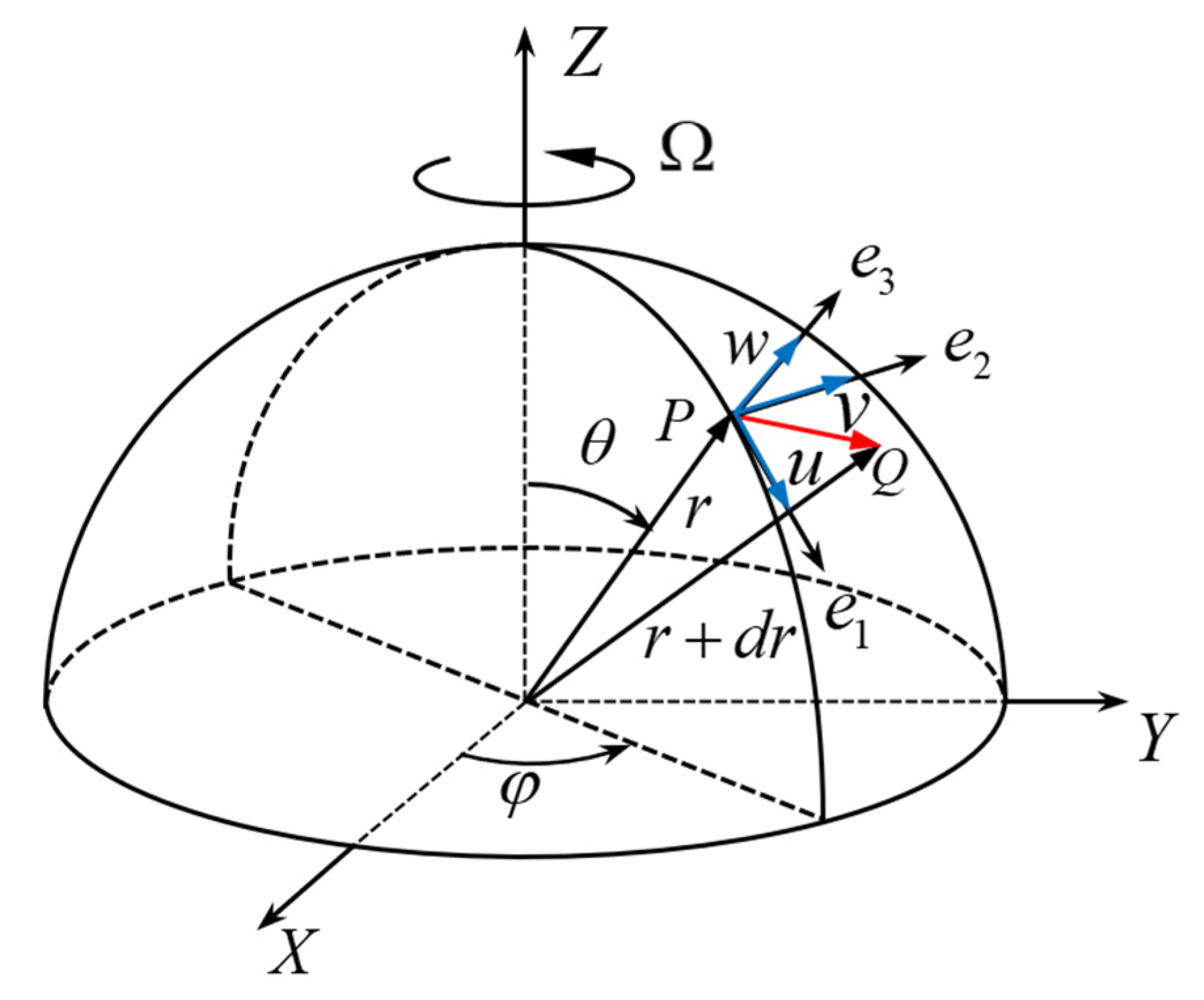
This paper is based on a thin hemispherical shell model, and mechanical analysis of the thin hemispherical shell is conducted using a spherical coordinate system. As shown in
Figure 1, the center of the hemispherical shell is selected as the origin of the coordinate system, with the corresponding coordinate parameters denoted as r, θ, φ, where θ ∈ [0, π/2] and φ ∈ [0, 2π]. The displacement components along the three directions are denoted as u, v, w.
To incorporate the effect of external forces, the force balance equation for a micro-element on the hemispherical shell under external loads is established. This leads to the derivation of the resonator’s second-order vibration equation. From this equation, the relationship between frequency splitting and the amplitude of the fourth harmonic component of the circumferential thickness variation can be determined. In this context, the primary external force considered is the electrostatic force applied radially to the hemispherical shell. Accordingly, the equilibrium equation balancing the external, internal, and inertial forces acting on a shell micro-element is formulated. The specific derivation proceeds as follows:
When the input angular velocity is
Ω, the absolute acceleration of any micro-element on the resonator’s hemispherical shell, according to the Rivas formula [
1], is given by:
where
S is the vibration amplitude and
t is the vibration time, After coordinate system transformation, the components of the absolute acceleration along the three local coordinate axes (
e1,
e2,
e3) are expressed as follows:
Therefore, according to Newton’s second law, the inertial forces of the hemispherical shell micro-element in the three directions(
e1,
e2,
e3) can be obtained as follows:
where
ρ is the material density of the resonator and h is the thickness of the hemispherical shell of the resonator, According to the theory of vibration mechanics, the internal force acting on any micro-element of the hemispherical shell in the vibrating state is:
where
ω0 is the natural frequency of the
n = 2 in-plane vibration mode of the resonator’s circumference. Thus, using Equations (3) and (4), according to D’Alembert’s principle, the force balance equation of any micro-element on the middle surface of the hemispherical shell is established:
In the equation, Fe1, Fe2, Fe3 are the external forces acting on the micro-element in the three directions e1, e2, e3, respectively. Among them, Fe3 is the electrostatic force during the operation of the gyroscope, which is the main external force, and the external forces in the other two directions can be ignored.
According to the Bubnov-Galerkin method, the second-order vibration equation of the hemispherical shell of the resonator under external forces is solved [
26]:
In the equation:
where
U(
θ),
V(
θ),
W(
θ) denotes the Rayleigh dissipation function, which is a quadratic function of the generalized velocities. By substituting the expression of the circumferential thickness error into the second-order vibration Equation (6) and solving it again, the second-order vibration equation of the hemispherical resonator with the error of uneven circumferential distribution of thickness is obtained:
By establishing the state equation of the vibration displacement and velocity of the hemispherical shell of the resonator, and solving the eigenvalues of the system matrix of the state equation, the natural frequency of its second-order vibration can be calculated [
26]. The mathematical expression of the natural frequency is:
For the hemispherical resonator, the hemispherical shell part is not a complete hemispherical shell due to the existence of the middle support rod. To make the model more close to the actual situation, the influence of the support rod is fully considered, and it is simplified as a hemispherical shell with a circular hole at the top, as shown in
Figure 2. According to the structural parameters of the resonator, the value range of the angle
θ is calculated to be [11.94°, 90°], i.e., the top angle is 11.94° and the bottom angle is 90°, which is used to accurately calculate relevant parameters such as
m0,
m1,
b0,
e1.
Equation (8) indicates that the second-order natural frequency of the resonator is influenced by both the input angular velocity and the relative amplitude of the fourth harmonic of the circumferential thickness error. When the amplitude of the fourth harmonic thickness error is constant, the frequency splitting increases with the angular velocity. Furthermore, the sensitivity of the frequency splitting to angular velocity variations differs for different values of the harmonic amplitude. Similarly, for a given harmonic amplitude, the resultant frequency splitting increases with angular velocity, while the sensitivity of the frequency splitting to changes in the harmonic amplitude gradually decreases. Consequently, in the full-angle mode operating over a large dynamic range, the frequency splitting induced by the fourth harmonic thickness error has a negligible effect on gyroscope precision.
When the input angular velocity is zero, the frequency splitting is expressed as
Further, the series expansion of Equation (9) is carried out to obtain the numerical relationship between the frequency splitting
Δω and the relative amplitude of the fourth harmonic of the thickness error
εh4:
For the actually machined resonator, multiple measurements show that the relative amplitude of the fourth harmonic of its thickness error is a small value, with
εh4 < 0.001. Therefore, the influence of the high-order terms in Equation (10) can be ignored, and the numerical relationship between the frequency splitting
Δω and the relative amplitude of the fourth harmonic of the thickness error
εh4 is expressed as the linear relationship shown in Equation (11):
At the same time, the numerical relationship between the frequency splitting
Δω and the amplitude of the fourth harmonic of the thickness error
h4 is obtained as shown in Equation (12), that is, when the amplitude of the fourth harmonic of the uneven circumferential thickness error is 1 μm, the frequency splitting of the hemispherical resonator is 3.873 Hz.
3. High-Precision Meshing Method of Hemispherical Resonators Based on ANSYS
Finite element analysis is conventionally employed to simulate the modal parameters of hemispherical resonators. The accuracy of the solution is highly dependent on the quality of the mesh generation. Traditional meshing techniques, however, typically yield simulation results with only Hertz-level accuracy. This stands in stark contrast to the millihertz-level frequency splitting observed in contemporary product-level hemispherical resonators. (“Millihertz-level” refers to a simulation precision where the frequency split (Δf) is better than 1 millihertz.) Although mesh refinement and standardization can be applied to enhance accuracy, simply increasing mesh density is insufficient to achieve millihertz-level precision and often drastically compromises computational efficiency.
To address these limitations, this paper proposes a uniform partitioning-based simulation methodology for hemispherical resonators. This approach offers the advantages of operational simplicity, low complexity, high computational efficiency, and the capability to achieve millihertz-level simulation precision.
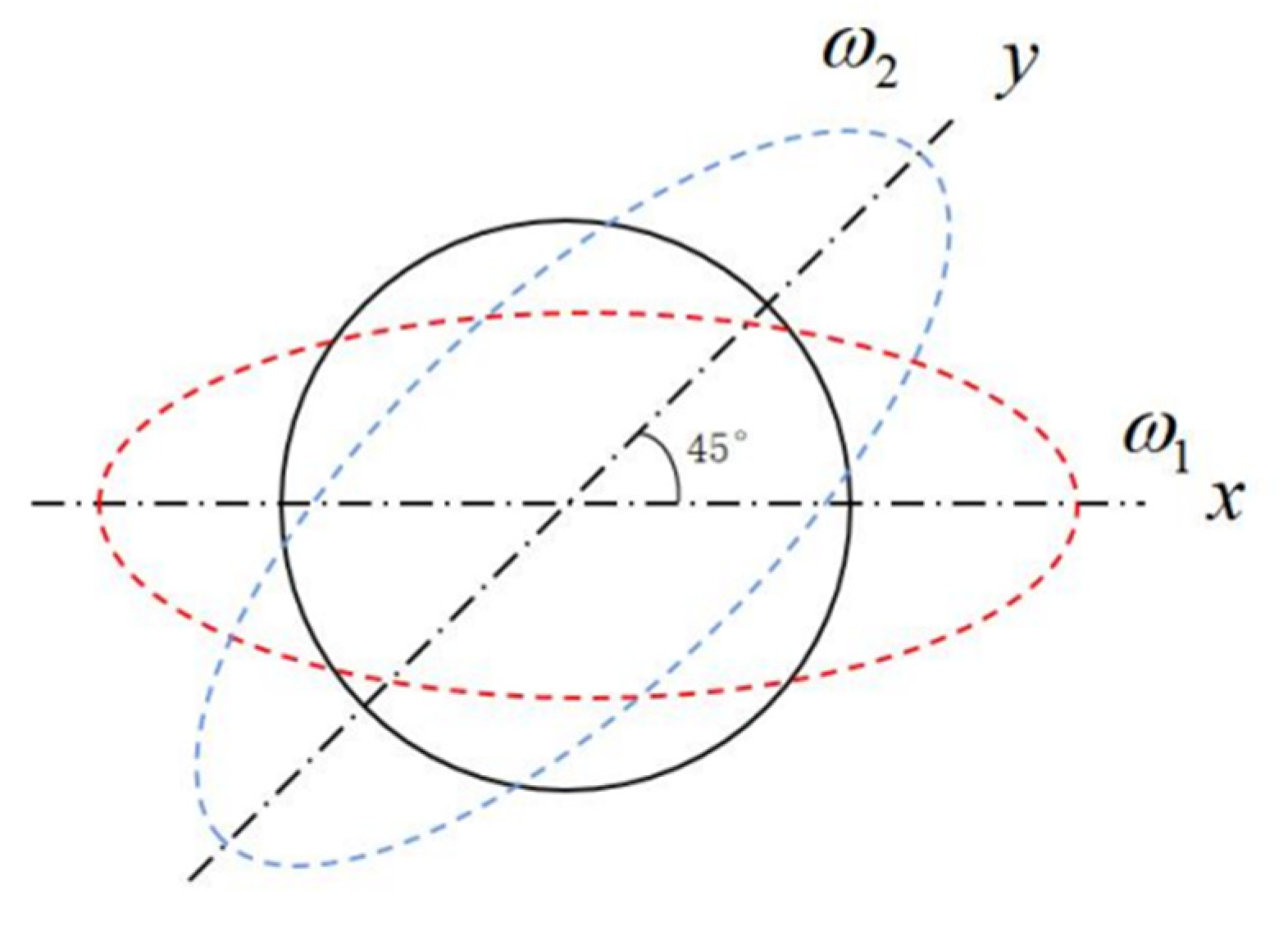
The ideal mesh for resonator analysis in ANSYS 2020 R1 would possess perfect rotational symmetry; that is, any sector of angle θ1, when rotated by an arbitrary angle θ2, would coincide exactly with the mesh in the new position, ensuring consistent and uniform mesh quality throughout. Since this ideal is practically unattainable, we propose a partitioning method. This involves first uniformly partitioning the hemispherical resonator geometry in SolidWorks 2022 and then importing the partitioned model into ANSYS for individual meshing of each segment. This strategy ensures that, even if local variations in mesh quality exist within individual partitions, the overall mesh quality is statistically equivalent across all partitions.
As illustrated in
Figure 3, the red area represents the circumference of the hemispherical resonator, while the blue distribution corresponds to the fourth harmonic of its mass inhomogeneity. To nullify the influence of the fourth harmonic mass inhomogeneity during meshing, the proposed concept dictates that the hemispherical shell be divided into 4N (where N = 1, 2, 3, …) sectors. A 90° rotation of these sectors results in a configuration that is mass-equivalent to the original. Similarly, to suppress the first, second, and third harmonics of mass inhomogeneity, the resonator should be partitioned into N, 2N, and 3N uniform sectors, respectively. By ensuring mesh uniformity within each of these sectors, the overall mass distribution is rendered uniform, building upon the foundation of consistent total mass for the major sector divisions.
The hemispherical resonator model was created in SolidWorks. Utilizing the ‘Split’ and ‘Combine’ features, the hemispherical shell was partitioned into 16 equal segments, while the central support stem was treated as a single segment, resulting in a total of 17 distinct bodies.
The partitioned model was then imported into the ANSYS Workbench Design Modeler module. The ‘Part’ function was employed to merge the segments, creating a single Part consisting of 17 Bodies. This step is crucial for ensuring node continuity at the shared boundaries between bodies during subsequent meshing, as illustrated in
Figure 4a.
Following this, the processed model was imported into the ANSYS Mechanical module for meshing. The MultiZone method was applied to the hemispherical resonator for initial mesh generation. All 17 bodies were selected as the meshing scope, with the mapped mesh type specified as hexahedral. Multiple Edge Sizing constraints were defined to control the mesh within each 22.5° sector. The first Edge Sizing constraint was applied to the lip circumference arc and the arc at the intersection of the shell’s transition fillet and the support stem, imposing 8 divisions per 22.5° sector. A second constraint was applied to the arcs along the generatrix of the hemispherical shell, specifying 30 divisions per arc. A third constraint governed the arcs along the generatrix of the transition fillet between shell segments, with 6 divisions on the inner surface and 3 divisions on the outer surface of each arc, as shown in
Figure 4b. All constrained arcs encompass both the inner and outer surfaces of the shell.
Face Meshing was utilized to discretize the upper and lower circular surfaces of the support stem separately. Since the mass inhomogeneity of the support stem has negligible influence on frequency splitting, its hexahedral mesh was refined without stringent control. The final mesh consisted of 32,968 elements and 152,027 nodes, as depicted in
Figure 4c. Set the maximum number of modes to 10 in the solver settings. Parameter Settings are shown in
Table 1.
Table 2 compares the simulation results of this method with other meshing approaches, demonstrating that it provides an effective means to achieve high-precision frequency splitting simulation results with significant advantages.
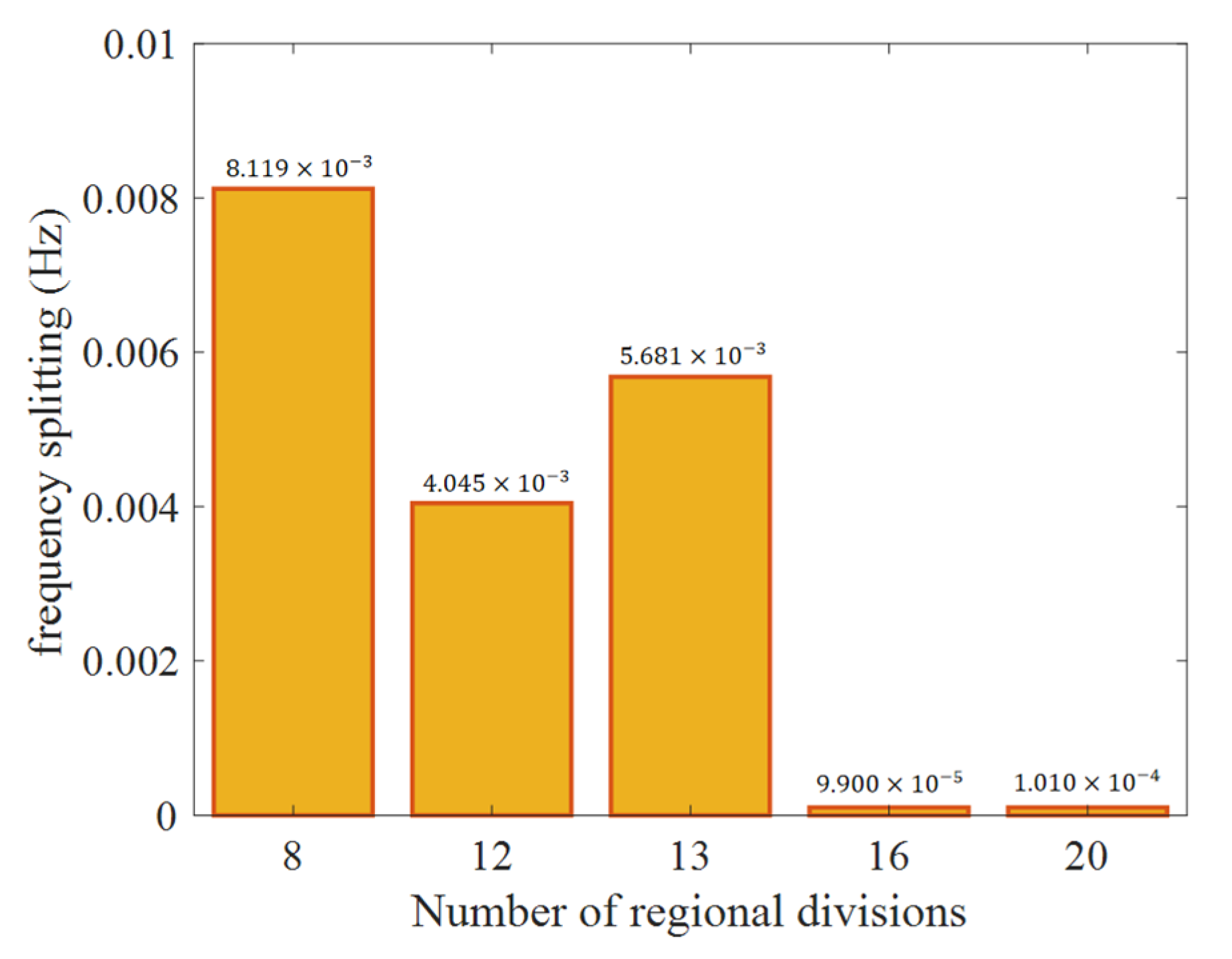
To evaluate the impact of mesh uniformity on simulation fidelity, the hemispherical resonator shell was partitioned into 8, 12, 13, 16, and 20 equal segments for comparative analysis. The corresponding simulation results are presented in
Figure 5.
Figure 5 reveals that simulation accuracy generally improves with an increasing number of partitions. Notably, when the number of partitions reaches 16, the simulated frequency splitting achieves millihertz-level accuracy. However, no further improvement in accuracy is observed when the number of partitions is increased to 20. This suggests that the mesh uniformity of the shell is already near-optimal at 16 partitions, and beyond this point, the mesh quality of the support stem becomes the limiting factor for accuracy.
A key observation is the decrease in simulation accuracy from 12 to 13 partitions, despite the increase in number. This anomaly aligns with and substantiates the underlying theoretical rationale, which posits that only specific partition numbers (integer multiples of the harmonic order) effectively suppress symmetry-breaking errors.
Summarizes the grid convergence study for the frequency split, performed using Richardson extrapolation. The monotonic decrease in relative error across the three grid levels confirms the convergence of the numerical solution. Although the extrapolated frequency split value at zero mesh size is negative—a result attributable to the fact that the frequency split is defined as a difference between two closely spaced natural frequencies—this is physically plausible. For subsequent analysis, the absolute value of the extrapolated result is adopted. To avoid sign-related artifacts, the two eigenfrequencies were extrapolated separately, with a convergence order of 2 and a refinement ratio of 3, demonstrating consistent mesh still convergence. As evidenced by the results in
Table 3 and
Table 4 and
Figure 5, achieving millihertz-level accuracy in the frequency split simulation necessitates not only an appropriate partitioning strategy but also a sufficiently refined and regular mesh within each partition. An inadequately dense or irregular mesh can introduce significant numerical errors that compromise the overall solution fidelity. Consequently, even a globally dense mesh that lacks the proposed partitioning framework fails to attain the required millihertz-level precision.
4. Simulation Analysis of the Influence of Hemispherical Resonator’s Form and Position Errors on Its Vibration Characteristics
The machining process of hemispherical resonators introduces form and position errors attributable to factors like grinding head wear and machine tool spindle rotational inaccuracies. These errors manifest as imperfections including shell thickness variation, mid-plane diameter deviation, end-face non-uniformity, and misalignment between the hemispherical shell and the support stem axes. In this section, a 3D model of the hemispherical resonator incorporating the aforementioned form and position errors is developed. Utilizing the high-precision meshing and finite element simulation methods detailed in the preceding section, we analyze the influence of these errors on the natural frequency and frequency splitting of the resonator, thereby identifying the dominant factors governing frequency splitting.
A 3D error model featuring a fourth harmonic circumferential thickness variation was created in SolidWorks. Specifically, the inner surface of the resonator’s hemispherical shell was defined as an ideal hemisphere with a radius of 10 mm. The outer surface, in contrast, was modeled as a non-ideal spherical surface, with its contour defined by Equation (13). This approach characterizes the fourth harmonic circumferential thickness distribution error through the relative thickness relationship between the ideal inner and non-ideal outer surfaces. The established error model is shown in
Figure 6, where the thickness distribution is the function value corresponding to the circumferential angle of the red curve
φ.
In Equation (13), r1 denotes the radius of the resonator’s outer spherical surface, and h4 represents the amplitude of the fourth harmonic component of the circumferential thickness variation. Modal analysis was conducted on hemispherical resonator models featuring different amplitudes of the fourth harmonic thickness error. This analysis yielded the natural frequencies and frequency splitting values corresponding to the four-wave (or 4-lobe) vibration mode.
A further analysis of the results demonstrates a linear correlation between the frequency splitting of the resonator and the amplitude of the fourth harmonic circumferential thickness variation. Quantitatively, a fourth harmonic thickness error amplitude of 1 μm induces a frequency splitting of approximately 5.38 Hz.
The preceding theoretical calculation predicted that a 1 μm fourth harmonic thickness error would induce a frequency splitting of 3.873 Hz. However, the finite element simulation yielded a larger value of approximately 5.38 Hz, as reported in the previous section. This discrepancy can be attributed to several factors:
First, the theoretical model relies on simplifying assumptions, such as an inextensible middle surface, constant radial thickness, and neglected normal stress between surfaces. Second, there is a fundamental difference in the solution approach. The theoretical model is continuous, yielding a closed-form solution, whereas the finite element model is discretized into interconnected nodes and elements, with modal parameters derived by solving global mass and stiffness matrices. Third, the model fidelity differs. The theoretical analysis simplifies the resonator as a pure hemispherical shell, while the finite element analysis employs a detailed 3D model that accounts for the mass and geometry of the support stem.
In summary, several factors contribute to the discrepancies between finite element simulations and theoretical calculations. It is acknowledged, concurrently, that discretization errors intrinsic to the meshing process remain a source of numerical inaccuracy in the FEM results.
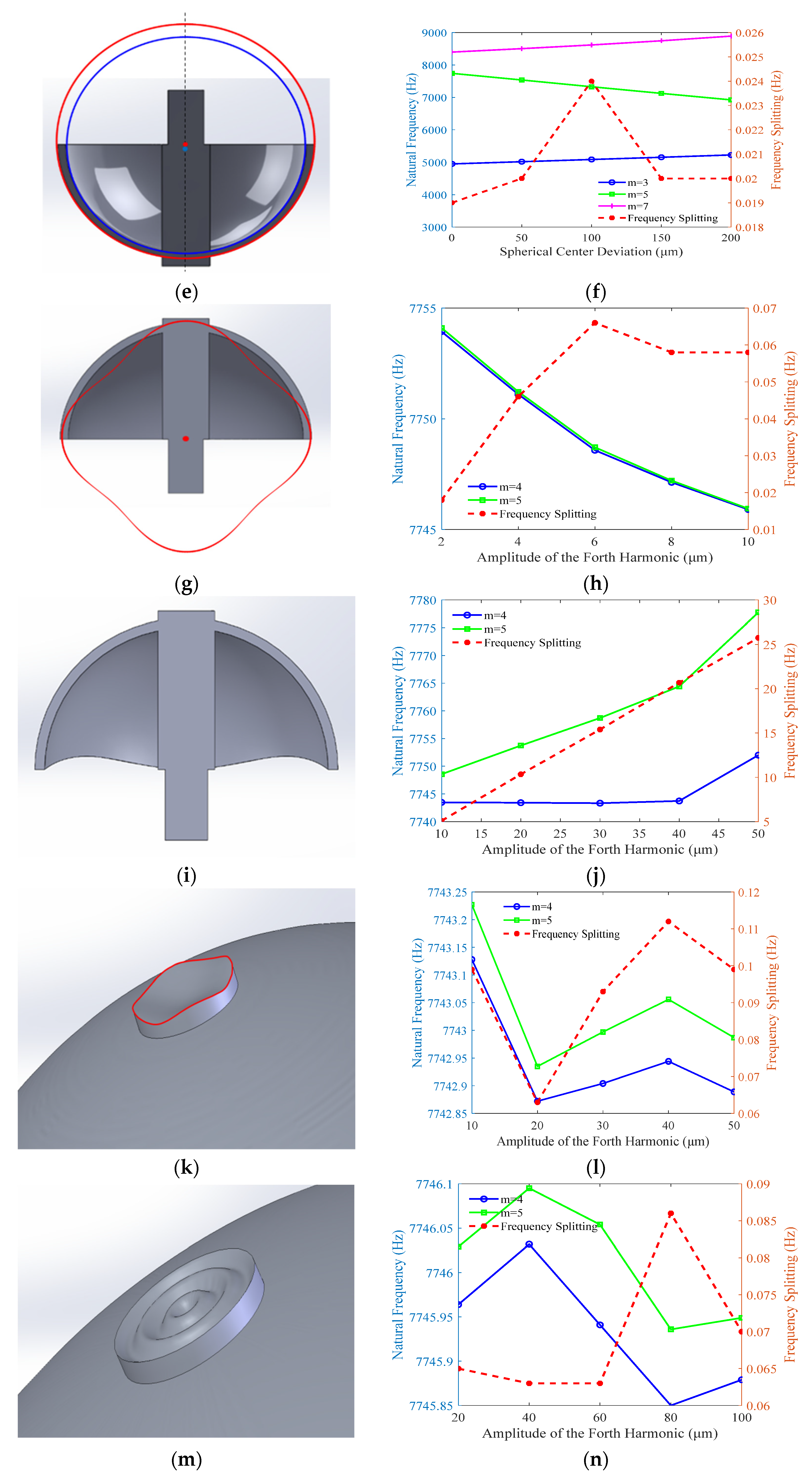
Furthermore, applying the same high-fidelity simulation methodology, a comprehensive set of error models was established to quantify the impact of various other imperfections on frequency splitting. These models, illustrated in
Figure 7, include: first and second harmonic circumferential thickness errors, generatrix-direction errors in thickness and mid-plane diameter, a fourth harmonic error in the shell’s end-face shape. errors in the support stem’s upper end-face, including circumferential height (fourth harmonic) and radial height variations, axes eccentricity and tilt between the hemispherical shell and the support stem.
The influence of each of these errors on the resonator’s frequency splitting was systematically analyzed.
High-precision finite element analysis was performed to determine the modal parameters of hemispherical resonators with various imperfections.
Figure 7a–d depict the variation in the natural frequency and frequency splitting of the operational vibration mode with respect to the amplitudes of the first and second harmonic thickness errors. The analysis indicates that a fourth harmonic thickness error with an amplitude of 2 μm can induce frequency splitting on the order of 10 Hz. In contrast, the frequency splitting caused by first and second harmonic errors of the same amplitude remains at a level of 0.2 Hz or lower. This conclusively demonstrates that the fourth harmonic of the circumferential thickness error is the dominant factor affecting frequency splitting. Consequently, during the resonator’s machining process, paramount importance must be placed on controlling the fourth harmonic circumferential thickness distribution, striving to suppress its amplitude to the nanometer level.
Figure 7e illustrates an error model featuring a vertical offset (0–200 μm) between the centers of the inner and outer spherical surfaces. The modal analysis, encompassing the m = 3, 4, and 5 modes, reveals the trends shown in
Figure 7f. As the offset increases, the natural frequency of the m = 4 working mode decreases, facilitating its excitation. Conversely, the natural frequency of the m = 3 mode increases, progressively narrowing its separation from the working frequency and thus posing a risk of interference. Notably, the spherical center offset has a negligible impact on frequency splitting itself, which remains around 0.02 Hz without an observable trend. This phenomenon can be leveraged to design resonators with intentionally tailored thickness profiles, effectively reducing the excitation frequency while maintaining satisfactory vibrational characteristics.
An error model for mid-plane diameter imperfection is established, as shown in
Figure 7g. The results in
Figure 7h show that the natural frequency of the m = 4 mode decreases with increasing error amplitude, while the frequency splitting remains minimal (<0.1 Hz) without a clear correlation. This suggests that even-order harmonics of mid-plane diameter error do not contribute significantly to frequency splitting when the support stem axis aligns with the harmonic peak.
Regarding the shell’s end-face shape error (
Figure 7i), which arises from circumferential height variations, a fourth harmonic error amplitude of 10–50 μm was investigated. The results (
Figure 7j) show that the resonant frequency of the m = 4 mode remains stable. In contrast, the frequency of the m = 5 mode and the resultant frequency splitting increase nearly proportionally with the error amplitude.
The influence of the support stem’s upper end-face shape error was analyzed, as the lower end-face is constrained. Error models for circumferential (fourth harmonic, 10–50 μm) and radial (20–100 μm) unevenness were created (
Figure 7k,m). The results (
Figure 7l,n) indicate that even with large error amplitudes, the induced frequency splitting is relatively small and shows no consistent trend, demonstrating the low sensitivity of vibrational characteristics to the stem’s end-face errors.
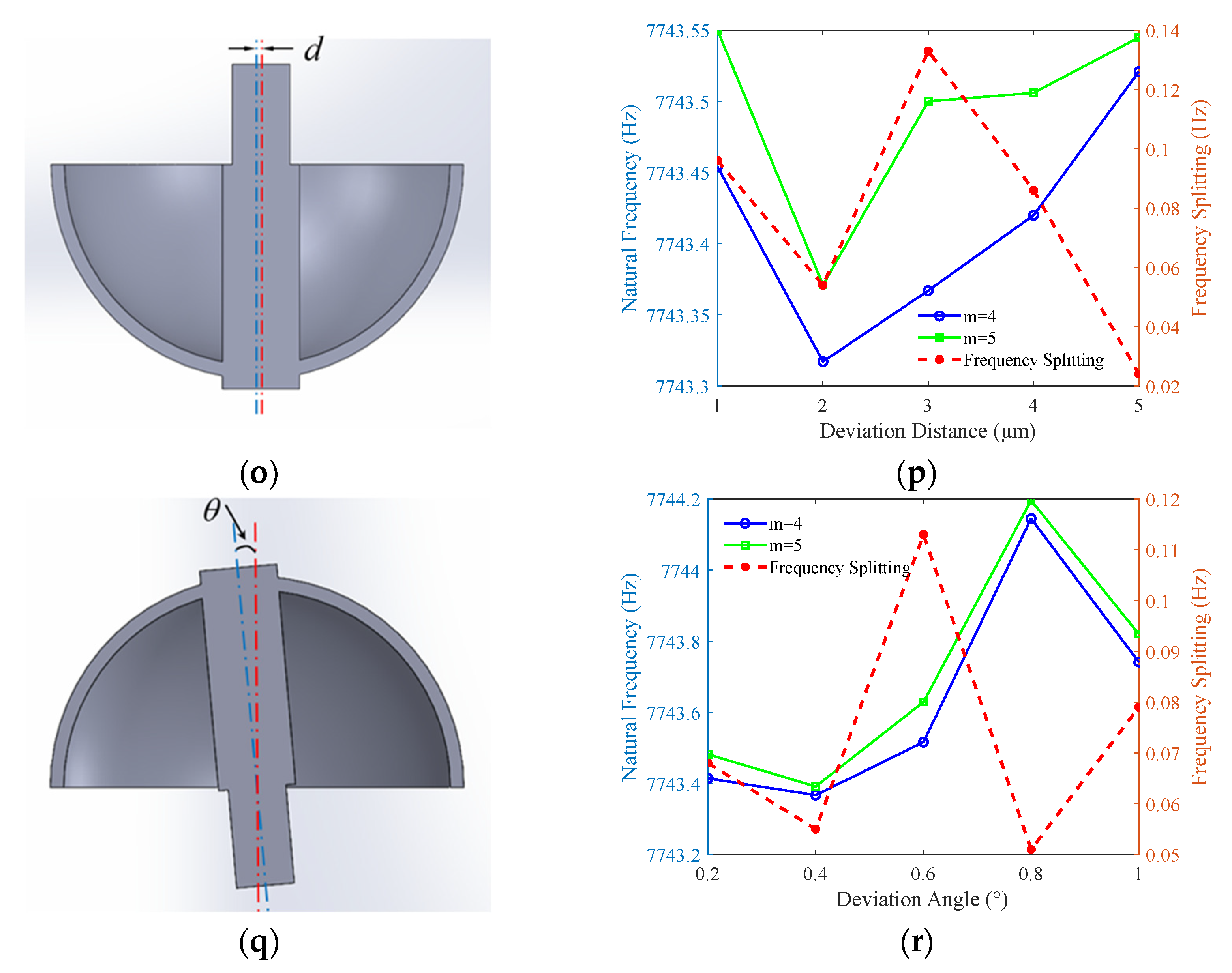
Finally, coaxiality errors between the shell and stem were investigated, considering parallel axis eccentricity error d (1–5 μm,
Figure 7o) and axis tilt θ (0.2–1°,
Figure 7q). The results (
Figure 7p,r) show that both errors have only a minor effect on the natural frequency and frequency splitting of the working mode, with values fluctuating slightly and stabilizing. However, these errors shift the resonator’s center of mass, significantly impacting low-order modes (e.g., shell swing). This increases energy dissipation, shortens the vibration decay time, and is thus detrimental to operational performance.
In summary, this study demonstrates that circumferential thickness variation and end-face height non-uniformity in the hemispherical resonator are the predominant factors governing frequency splitting, and thus must be prioritized in design and manufacturing control. Although axis misalignment errors (eccentricity and tilt) between the shell and support stem exhibit a secondary effect on frequency splitting, their significant impact on the quality factor necessitates stringent control. Furthermore, the identified reduction in excitation frequency associated with spherical center offset presents a valuable design parameter, offering a pathway for the performance optimization of future resonator designs.
The dimensional imperfections investigated in this study are on the micrometer scale, yet their impacts on frequency splitting manifest at two distinct orders of magnitude: hertz-level and millihertz-level. Errors inducing hertz-level splitting exert a substantial influence on resonator performance, necessitating stringent control during machining and design. In contrast, errors resulting in millihertz-level effects are considered negligible for most practical purposes, given the orders-of-magnitude difference in their impact. The observed millihertz-level fluctuations across repeated solver runs are attributed to numerical discretization errors inherent in the 3D modeling process, which introduce minor inconsistencies in mesh generation.
5. Simulation Analysis of the Quality Factor of Hemispherical Resonators
In this section, a parametric analysis framework is developed for hemispherical resonators to qualitatively investigate the relative trends of influence exerted by various defect types and geometric parameters on energy dissipation. The finite element simulations performed here primarily consider thermoelastic damping as the energy loss mechanism. It should be noted, however, that for fused quartz materials, the contribution of this mechanism is relatively weak and does not constitute the main factor limiting the actual Q-factor of the resonator. Therefore, the absolute Q-factor obtained in the following analysis do not correspond to actual device performance. Instead, the objective of this study is to employ the model as a parameter sensitivity analysis tool to examine how different defect morphologies comparatively affect energy loss, thereby offering qualitative insights for process control.
A hemispherical resonator experiences various forms of energy loss during free vibration. The quality factor (Q-factor) of the resonator is defined as 2
π the ratio of the resonator’s initial energy (
E) to the energy lost (Δ
E) by the end of one vibration cycle, expressed as follows:
A high Q-factor signifies low energy dissipation per oscillation cycle, which directly translates to a long vibration decay time constant. For instance, a resonator with a Q-factor on the order of 10
7 can sustain its operational vibration for several minutes after the driving power is disconnected [
1]. This attribute ensures continued gyroscope functionality during emergency power loss and enhances its overall measurement sensitivity. Therefore, a thorough analysis of the Q-factor and the implementation of machining strategies to maximize it are of critical importance.
The definition of the Q-factor reveals that its value is intrinsically governed by the rate of energy dissipation: a higher dissipation rate results in a lower Q-factor. In hemispherical resonators, energy dissipation mechanisms are primarily categorized as air damping (or anchor) loss, surface loss, support loss, and thermoelastic damping (TED). These loss mechanisms are comprehensively captured by the following expression (Equation (16)) [
2]:
These loss mechanisms can be classified into two categories. The first category is intrinsic, being governed by the material properties and the resonator’s inherent structure; this includes TED and internal friction. The second category is extrinsic, encompassing losses controlled by external factors such as air damping, support loss, and surface loss.
In theory, intrinsic losses cannot be entirely eliminated but can only be minimized through superior material selection and structural optimization of the resonator. In contrast, extrinsic losses can be significantly suppressed, or even virtually eliminated, by controlling the resonator’s operational environment and manufacturing processes. Examples include maintaining a high-vacuum environment to mitigate air damping, employing precision machining to reduce surface and support losses, and applying post-fabrication surface treatments to enhance surface quality. Therefore, the analysis and deliberate mitigation of these extrinsic loss mechanisms during manufacturing are paramount for achieving high-Q resonators.
Among these, surface loss constitutes a critical yet not fully elucidated mechanism that significantly limits the achievable Q-factor. Prevailing hypotheses attribute it to surface micro-cracks, water adsorption, and surface bond oscillation. However, limited research has been conducted to quantify its impact on small-sized, thin-walled structures such as hemispherical resonators. The machining of fused silica resonators, due to the material’s high brittleness, inevitably induces subsurface damage during grinding and polishing. Such damage can propagate during operation, leading to a degradation in both the Q-factor and the long-term reliability of the resonator.
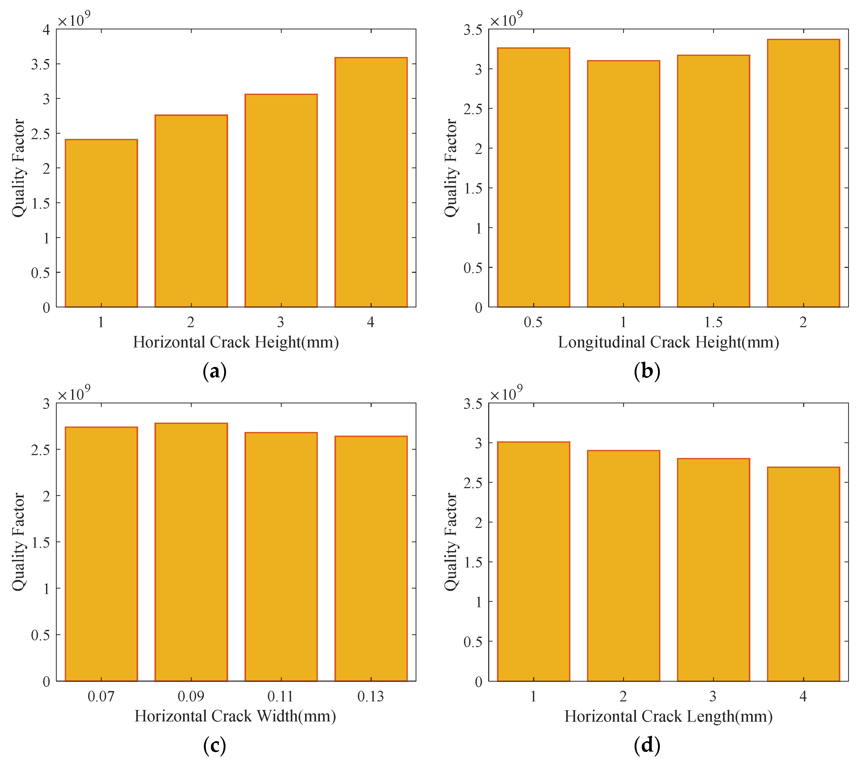
In this work, finite element simulations are employed to systematically investigate the influence of surface cracks—varying in location and size—on the Q-factor of hemispherical resonators. The simulation results are presented in
Figure 7.
Figure 8a,b present the simulation results quantifying the impact of transverse and longitudinal cracks (of equal length) on the Q-factor, as a function of their vertical position along the resonator’s lip.
Figure 8a reveals that the simulated Q-factor shows a clear increasing trend as the transverse crack is positioned higher along the lip. In contrast,
Figure 8b shows that the Q-factor fluctuates without a clear trend with increasing longitudinal crack height, indicating a negligible overall influence. Furthermore, the impact appears to diminish at higher positions.
Given the pronounced sensitivity to transverse cracks, their geometric influence was investigated further.
Figure 8c,d simulate the effects of transverse crack width and length, respectively, on the Q-factor. As shown in
Figure 8c, the Q-factor displays minor fluctuations with increasing crack width but no consistent trend, suggesting that width variation has a minimal effect. In stark contrast,
Figure 8d demonstrates a clear decreasing trend in the simulated Q-factor with increasing length of the transverse crack.
In summary, these results underscore that machining processes must prioritize the avoidance of long transverse cracks, particularly those near the resonator’s lip, to preserve a high Q-factor.
In addition to surface loss, Support loss is another key factor affecting the Q-factor, arises primarily from the resonator-fixture connection, intrinsic material density inhomogeneity, and mass imperfections introduced during machining. It is important to note that the current model primarily captures the effects related to mass inhomogeneity and its interaction with the support structure through thermoelastic coupling. The actual support loss mechanism in a physically realized resonator involves complex factors at the anchoring interface (e.g., adhesive layer properties, connection geometry, and symmetry) which are not encompassed by this simulation. Therefore, the results presented here should be interpreted as revealing the potential trend of how mass imbalance may influence energy dissipation, while the absolute magnitude of support loss requires further investigation with more sophisticated models.
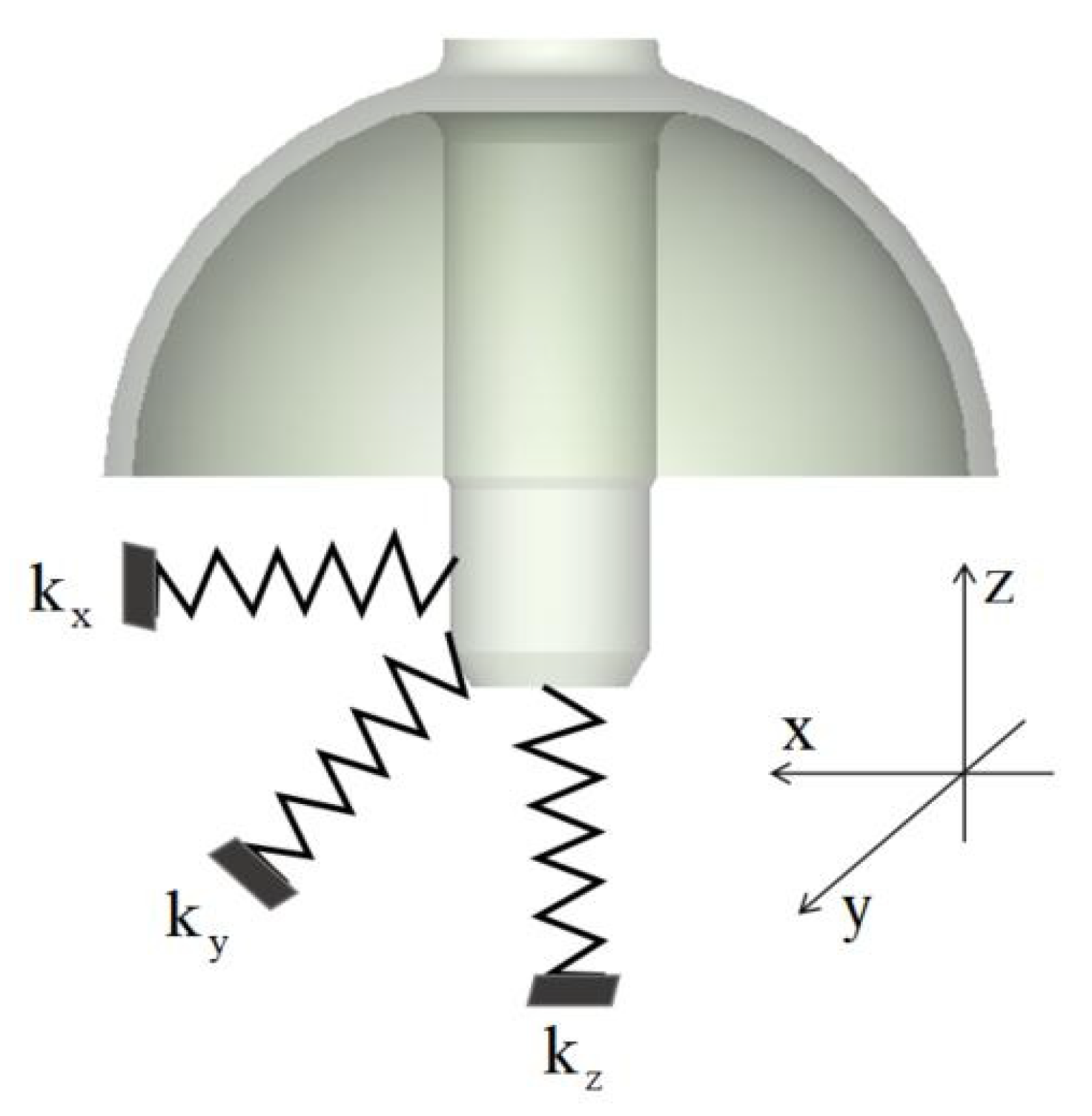
As shown in
Figure 9, the resonator’s central rod serves as the clamping location. The elastic stiffness of the fixture in the x, y, and z directions is denoted as
kx,
ky and
kz, respectively. The support forces between the fixture and the resonator are given by [
27].
where
A is the amplitude of the resonator,
ω is the natural frequency of the resonator,
mn is the n-th order unbalanced mass of the resonator,
φn is the phase angle of the n-th order unbalanced mass, and θ is the azimuth angle of the standing wave. The dynamic equation of the resonator’s central rod, considering the support forces, can be expressed as follows:
where
X,
Y and
Z are the displacements of the resonator’s central rod in the three directions, and
ζ is the damping coefficient in the three directions. The energy loss in the X-direction over one period is then given by:
The total energy loss is:
This study employs finite element simulation to analyze the impact of the first, second, third, and fourth spatial harmonics of mass (density) inhomogeneity on the Q-factor.
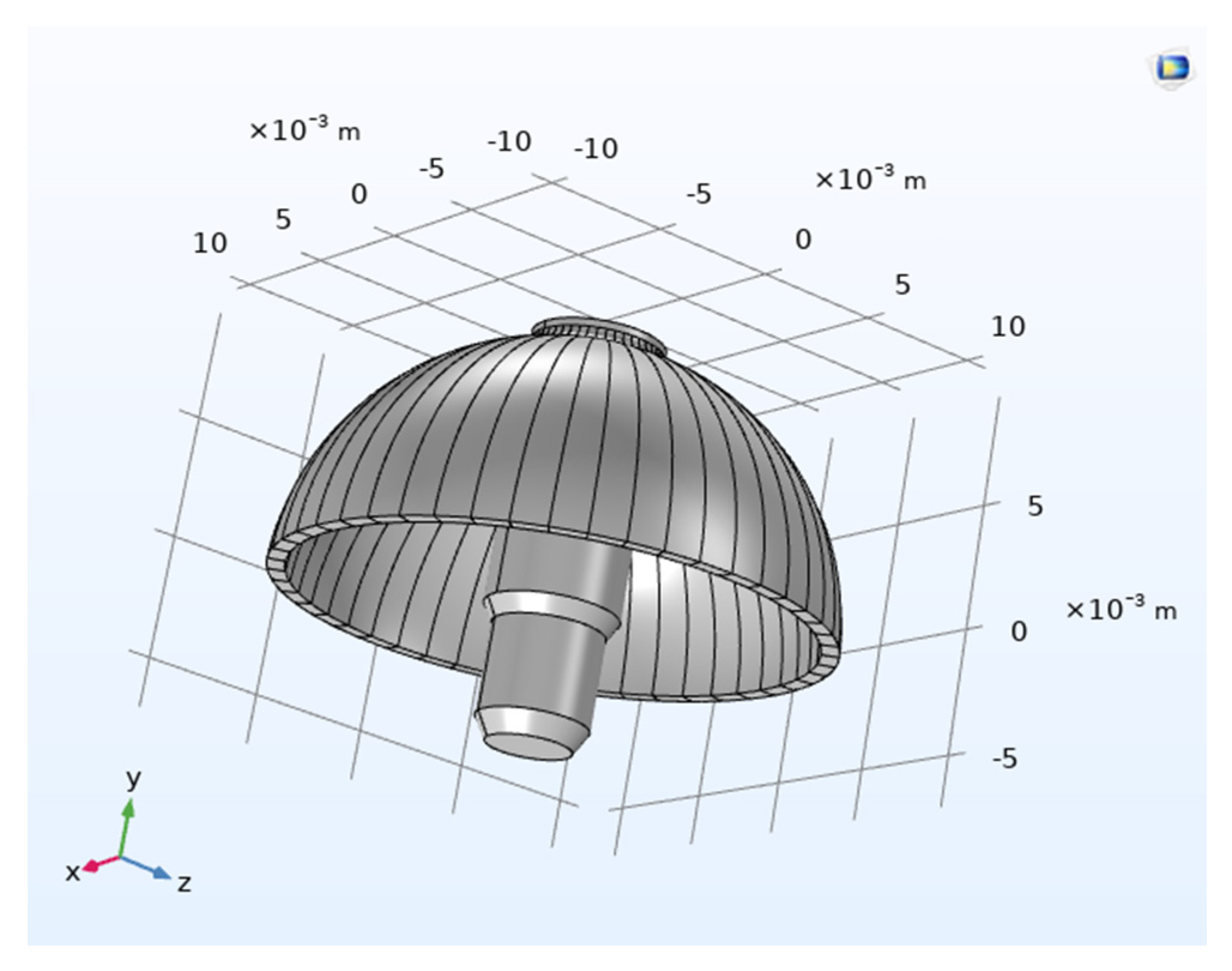
To simulate the first, second, third, and fourth spatial harmonics of mass inhomogeneity, the resonator geometry was discretized into 48 equal sectors. Mass inhomogeneity was implemented by assigning a spatially varying density to each sector in COMSOL multiphysics 5.6, following a sinusoidal distribution corresponding to the target harmonic, as illustrated in
Figure 10.
In practical manufacturing, hemispherical resonators inherently exhibit mass inhomogeneity due to machining imperfections. In this study, this mass asymmetry is modeled via spatially varying density. Based on the formulas for the first to fourth harmonics of the mass imbalance Fourier transform, the density was set with a minimum of 2205 kg/m3 and a maximum of 2220 kg/m3. The density value for each segment was calculated separately and then sequentially added to the model parameters. In practice, hemispherical resonators inevitably exhibit mass imbalance due to manufacturing imperfections. In this simulation, such imbalance is modeled via deliberate density variation across the resonator structure. It should be emphasized that the primary objective of this simulation is to evaluate the relative influence trend of different mass imbalance harmonics on the simulated energy dissipation, rather than to obtain quantitatively precise Q-factor values. A relatively wide density variation range was selected to ensure clear and analytically distinguishable trends.
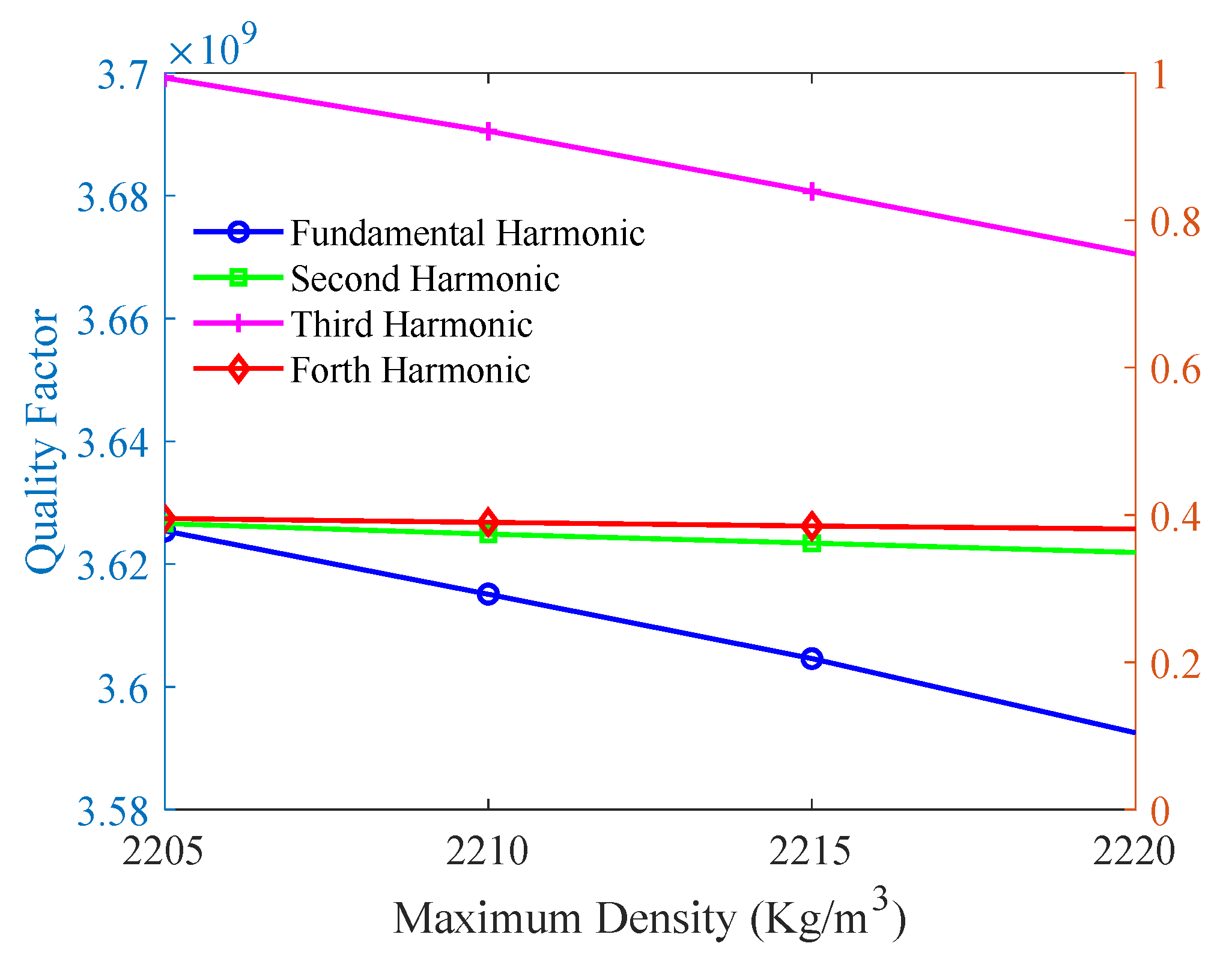
The model was meshed, and the COMSOL simulation was configured with the ‘Solid Mechanics’ and ‘Solid Heat Transfer’ modules. The ‘Thermal Expansion’ multiphysics coupling was activated to interlink the mechanical and thermal analyses. Within the thermal expansion settings, the contributions of thermoelastic damping and mechanical loss were enabled as heat sources, allowing for the subsequent computation of the Q-factor. The Q-factor exhibits circumferential heterogeneity but is repeatable at identical spatial locations. Consequently, all measurements must be acquired from a consistent reference position. The high-frequency natural rigid axis was selected as this reference, as it corresponds to the circumferential location of the maximum Q-factor, thereby providing a representative and optimal baseline for evaluation. Owing to the spatial inhomogeneity of the computed Q-factor, the value at the location of the high-frequency natural rigid axis was adopted as the representative Q-factor for the resonator. The simulation results are presented in
Figure 11. The high-frequency natural rigid axis is presented in
Figure 12.
The results indicate that the first and third harmonics of mass inhomogeneity exhibit the most substantial impact on the simulated energy dissipation trend, which shows a clear increase with rising inhomogeneity amplitude. In contrast, the second harmonic demonstrates a comparatively minor effect, while the fourth harmonic shows a negligible influence on the simulated energy loss trend.
Table 5 displays the simulation parameter settings in COMSOL.
6. Conclusions
This study established a numerical correlation between frequency splitting and the amplitude of the fourth harmonic thickness error, derived from a dynamic model that incorporates external loads. A high-precision meshing methodology was developed and applied to 3D models of hemispherical resonators incorporating various machining-induced form and position errors. The simulation results conclusively identify the fourth harmonic components of circumferential errors—specifically in shell thickness, mid-plane diameter, and end-face shape—as the dominant factors responsible for frequency splitting.
Furthermore, a systematic investigation into factors influencing the resonator’s quality factor (Q-factor) was conducted. The analysis of crack geometry—including orientation, vertical position, width, and length—revealed that transverse crack length demonstrates the most significant correlation with increased energy loss trends in the simulation. Regarding mass distribution imperfections, the simulation results indicate that the first and third spatial harmonics of mass inhomogeneity exhibit a more substantial impact on the simulated energy dissipation trends compared to the second and fourth harmonics, which show relatively smaller influences.
