Abstract
Reverse osmosis (RO) water purifiers produce a large volume of reject water, which is typically discarded, leading to water wastage and resource inefficiency. This work proposes a novel approach to reusing RO effluent as a cooling medium in a water-cooled condenser integrated into a residential hot-and-cold water purifier. The system replaces a conventional air-cooled condenser with a water-cooled unit and was evaluated under controlled laboratory conditions (ambient temperature 25 °C). Experiments were conducted at various RO effluent flow rates ranging from 0.5 to 2.5 L per minute (LPM). Key performance metrics, including the coefficient of performance (COP), cooling time, and energy consumption, were measured and compared. Results showed that replacing a conventional air-cooled condenser with a water-cooled condenser configuration reduces energy consumption by up to 37.5% and shortens cooling times by up to 33%. Performance was maintained under intermittent RO effluent supply. However, an excessive flow rate (2.0 LPM) caused evaporator frosting and efficiency loss, indicating the importance of flow control. These findings demonstrate that internally reusing an RO effluent offers a sustainable, compact, and energy-efficient solution for next-generation water purifiers.
1. Introduction
In recent decades, the adoption of water purification systems in residential and commercial settings has increased significantly due to the pursuit of health-conscious lifestyles and rising living standards. This trend is particularly pronounced in densely populated urban areas, where concerns about tap water quality and increased trust in municipal water treatment infrastructure have led many consumers to rely on home filtration systems. According to global monitoring data, household access to better-quality drinking water has expanded, and consumer reliance on point-of-use treatment technologies has become more common in both developed and developing countries [1,2]. In the US and some parts of Europe, the home water purifier market is experiencing steady growth due to aging water infrastructure and increasing awareness of emerging contaminants [3]. Meanwhile, in many low- and middle-income countries in Asia and Africa, demand for decentralized water treatment solutions is rapidly increasing due to local government supply instability and concerns about microbial contamination [4,5]. Market reports in Korea also show a high penetration rate of water purifiers in urban households [2].
As demand for water purification systems has grown, technologies have diversified. Ultrafiltration, nanofiltration, ceramic filtration, activated carbon adsorption, and reverse osmosis (RO) are the most common filtration techniques. Among these, RO systems account for over 60% of high-end water purifier sales in Asia and over 70% worldwide due to their superior contaminant removal capabilities [6,7]. RO membranes, with pore sizes as small as 0.0001 microns, effectively remove over 99% of dissolved solids, bacteria, heavy metals, viruses, and various organic contaminants [8,9]. However, RO systems have a drawback. Importantly, a significant portion of the feedwater (typically 60–80%) is discharged as effluent (or “drainage”), with only about 20–40% converted to purified permeate [6,10].
Waste water is constantly generated when using household RO water purifiers. It is usually discharged directly to the sewer, resulting in unnecessary water and heat losses. Since many homes discard up to several liters of wastewater per day, improving the utilization of this byproduct is crucial from both environmental and economic perspectives. However, wastewater contains various contaminants and chemical residues, making it impossible to reuse for drinking or agricultural purposes without further treatment. Therefore, recent research has focused on methods to more effectively manage or utilize RO effluent. These approaches include desalination/brine recovery (e.g., pressure-lag osmosis or membrane distillation) [11,12], reusing non-potable water (e.g., recovery water, as well as water from toilet flushing and industrial cooling) [13,14], and even repurposing the water within a device system (e.g., using effluent as a cooling medium in a heat exchanger [15]).
Despite the growing interest in reusing RO effluent, most existing research has focused on large-scale applications such as brine recovery, non-potable water reuse (e.g., irrigation or toilet flushing), and industrial process water systems [11,12,13,14,15]. Few studies have investigated how to reuse RO effluent in small household appliances, particularly as a secondary coolant in the condenser during a vapor compression cycle. Furthermore, no study has systematically compared conventional air-cooled condensers against RO effluent-based water-cooled condensers under identical operating conditions to evaluate condenser downsizing and energy efficiency improvements. To address this gap, this study investigates the integration of RO effluent into the closed-loop cooling circuit of a residential hot-and-cold water purifier and experimentally compares air-cooled and RO water-cooled condenser configurations in terms of size reduction potential, energy consumption, and overall system performance.
For domestic hot-and-cold water purifiers, chilled water is produced using a vapor compression cycle-based system. The vapor compression cycle uses a refrigerant as the working fluid, to repeat the condensation and evaporation processes. The condensation process utilizes an air-cooled condenser that exchanges heat with the outside air. While air-cooled condensers offer the convenience of using air as a heat source, they have performance limitations compared to water-cooled condensers. Therefore, many studies are exploring water-cooled systems instead. For example, a comparative study of natural and forced convection condensation in reinforced flat plates and tubes demonstrated significantly higher heat transfer coefficients in forced convection mode, particularly when surface enhancement was applied [16]. A study of fin plate geometries under forced convection conditions demonstrated that varying the plate spacing and fin dimensions significantly increased heat capacity and slightly increased pressure drop [17]. Field comparisons in large-scale cooling systems (e.g., hospital chillers in dry climates) demonstrated that water-cooled condensers consumed 30–45% less power and lowered daily energy use compared to air-cooled condensers during summer peak loads [18]. Similarly, studies on condenser optimization for residential refrigeration systems have shown that careful design of the wire-on-tube type, refrigerant selection, and airflow optimization can reduce the condenser area by approximately 10–15% without compromising performance [19]. Recent numerical studies have shown that incorporating internal waste heat (e.g., RO effluent) or alternative cooling streams as the secondary fluid in a compact heat exchanger can significantly improve energy recovery and thermal performance in residential systems [20]. Furthermore, experimental studies in a building environment have shown that replacing air-cooled condensers with water-cooled configurations using domestic tank water as a sink significantly reduces the compressor load, improves COP, and enhances operational stability under variable load conditions [21]. These results suggest that for residential water purifiers, switching from air-cooled condensers that utilize internal wastewater (e.g., RO effluent) to those that are water-cooled could potentially yield significant improvements in miniaturization, energy efficiency, and performance.
This study investigates RO effluent integration into the thermal management cycle of a residential hot-and-cold water purifier at the device level. The water purification device used in this study follows a typical multi-stage RO configuration, which consists of a sediment pre-filter, a pre-carbon filter, an RO membrane, and a post-carbon filter. The sediment pre-filter removes suspended particles such as rust and sand, while the pre-carbon filter adsorbs residual chlorine and organic compounds that can damage the RO membrane. The semi-permeable RO membrane then removes dissolved salts, heavy metals, and microorganisms at the molecular level, and the post-carbon filter further improves the taste and odor quality of the permeate [22]. During this process, a significant portion of the feedwater (typically at a pressure of 2 to 4 bar) is discharged as RO effluent. This pressure range is standard for domestic water systems and is sufficient to ensure adequate RO membrane performance. In this system configuration, the pressurized effluent is recirculated into a closed-loop circuit that serves as the cooling fluid for a small, water-cooled condenser. The closed-loop system minimizes complexity and energy consumption by eliminating the need for additional pumps or external pressurization devices. In this configuration, a conventional air-cooled condenser is replaced with a water-cooled heat exchanger that uses internally generated RO effluent as the secondary coolant. Because air-cooled condensers have a low heat transfer coefficient and require a large surface area for effective heat removal, water’s superior convective heat transfer capacity (approximately 50 to 100 times higher than that of air) is leveraged to lower the condensing temperature and enable condenser miniaturization. Furthermore, recycling the RO effluent within a closed-loop cooling circuit eliminates the need for external water supply or additional piping infrastructure, reducing material complexity and operating costs. To evaluate the effectiveness of this configuration, various controlled experiments were conducted to compare the thermal and energy performance of air-cooled and RO-water-cooled condenser configurations under identical operating conditions. Key performance indicators, including condenser surface temperature, refrigerant subcooling, compressor input power, and total energy consumption, were monitored to assess cooling performance and energy efficiency. These results provide important insights into the design potential of compact, energy-saving water purification systems and suggest a novel device-integrated reuse strategy for non-potable RO effluent.
2. Experimental Setup
An experimental system was constructed to evaluate the performance of a residential hot-and-cold water purifier incorporating a vapor compression refrigeration cycle (Figure 1). This system utilizes a hermetic compressor (1/10 hp) filled with R134a refrigerant. The refrigeration loop consists of a compressor, condenser, capillary tube, and evaporator, which were all connected by copper piping. The condenser is a wire-tube type air-cooled heat exchanger. It provides a total frontal surface area of about 300 cm2, and it is designed to operate under natural convection conditions without forced airflow. The inner diameter of the capillary is 0.6 mm, and its total length is 1.2 m. The evaporator is a coil-type heat exchanger immersed directly in the cool water storage tank of the purifier. It consists of a pipe with an outer diameter of 9.5 mm and a total length of 0.9 m arranged in a spiral pattern to maximize surface contact with water. After evacuation, the system is charged with a refrigerant and operates in a closed loop while the compressor is running. The refrigerant is drawn into the compressor as a low-pressure vapor, compressed, and discharged as a high-pressure, high-temperature gas. It then flows into the condenser for heat dissipation and phase change. The high-pressure liquid refrigerant expands as it passes through the capillary tube, becoming a low-pressure, low-temperature liquid. It then enters the evaporator, absorbing heat from the water in the water purifier’s cold-water container. The refrigerant then evaporates and returns to the compressor inlet as a low-temperature, low-pressure vapor, completing the cycle.
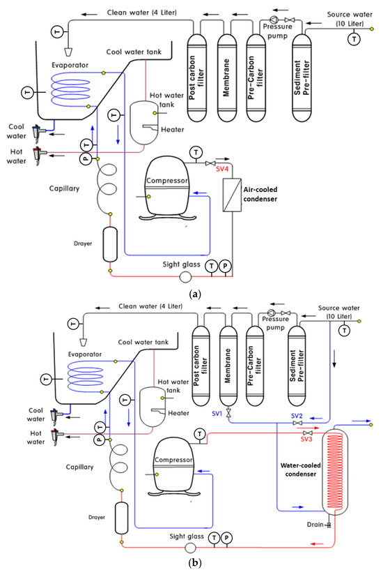
Figure 1.
Schematic diagram of the experimental apparatus: (a) air-cooled condenser cycle and (b) water-cooled condenser cycle.
All components except the water-cooled condenser were from commercially available water purifiers. For a comparative analysis of the water-cooled and air-cooled condensers, they were connected in parallel, and their operating modes were switched via a solenoid valve system. Solenoid valve SV4 induced fluid flow through the air-cooled condenser (Figure 1a), and SV3 induced fluid flow through the water-cooled unit (Figure 1b). When operating in water-cooled mode, SV1 supplied RO effluent as the cooling medium. When RO effluent was unavailable, SV2 operated to supply tap water to maintain a constant thermal environment.
The experiments were conducted in a temperature- and humidity-controlled chamber maintained at 25 ± 1 °C and 60 ± 5% RH, thereby maintaining a consistent ambient environment throughout the testing process, in accordance with standard test criteria [23]. Temperature sensors were installed at all key points to measure refrigerant and water temperatures. High and low-pressure gauges were used to measure system pressure, and a power meter was used to evaluate compressor energy consumption for both condenser configurations (Table 1).

Table 1.
Experiment specifications.
The water-cooled condenser is geometrically designed to mimic the dimensions of a standard filter housing, allowing for direct integration into existing water purifier structures. The outer shell is cylindrical, with an internal rolled copper coil acting as the refrigerant path. The RO effluent flows between the coil and the outer wall, forming a concentric flow heat exchanger. The overall system outline is shown in Figure 2, and the dimensional specifications of the water-cooled condenser are summarized in Table 2.
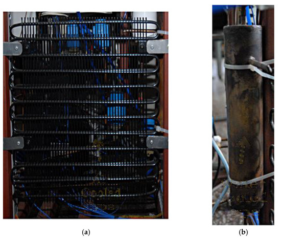
Figure 2.
External view of the two condenser configurations used in the experiment: (a) air-cooled condenser and (b) water-cooled condenser.
Table 2.
Geometric specifications of the water-cooled condenser.
Three experimental tests were conducted to evaluate and analyze the performance of the hot-and-cold water purifier.
First, COP, a fundamental performance indicator of the vapor compression refrigeration cycle, was evaluated. COP is calculated as the ratio of cooling capacity to power consumption during steady-state operation. In this test, the water tank of the purifier was supplied with water at a constant flow rate of 1 L per minute (LPM) and an inlet temperature of 25 °C. For systems equipped with a water-cooled condenser, the inlet water temperature was fixed at 25 °C, and the flow rate was varied from 0.5 LPM to 2.5 LPM to analyze its effect on COP.
where is the flow rate of water supplied to the evaporator, cp,w is the specific heat of water at constant pressure, Wcomp is the work required by the compressor of the cooling system, and Tw,i and Tw,o are the water temperatures at the inlet and outlet of the evaporator, respectively.
Second, a cooling rate test was conducted to observe the time required to lower the tank’s water temperature. Unlike the first test, which was designed to compare refrigeration cycle performance under controlled conditions, this test more closely simulated actual usage conditions. During the test, the cold water tank was filled with 25 °C water without additional supply. The refrigeration system was thwn turned on and the time it took to reach the target chilled water temperature of 4 °C was measured. This method is commonly referred to as a pull-down test.
Third, the dynamic-operation and energy-consumption tests were performed to simulate irregular usage patterns. During actual water purifier operation, users do not use cold water at a constant rate, so the tank is intermittently refilled with ambient temperature water. This causes the tank temperature to fluctuate, causing the refrigeration system to operate intermittently. To reproduce this behavior, a fixed volume of chilled water was periodically withdrawn so that the tank was refilled with ambient temperature water These tests aimed to evaluate the system’s responsiveness and power consumption under various usage patterns.
where E is the total energy consumption, and t1 and t2 represent the measurement period.
3. Results and Discussion
3.1. Comparison of Cooling Performance Between Air-Cooled and Water-Cooled Condensers
Figure 3 shows the COP of a water purifier cooling system for two condenser configurations: a conventional air-cooled condenser operating on natural convection and a proposed water-cooled condenser using RO effluent as the cooling medium. The RO effluent flow rate was evaluated from 1 to 3 lpm, with 0 lpm representing the conventional air-cooled condenser. Because the COP test was conducted as a steady-state test, the RO effluent temperature was maintained at a constant 25 °C. The COP of the water-cooled condenser using RO effluent was significantly improved compared to that of the air-cooled condenser. This performance improvement is consistent with well-established results in vapor compression systems, where replacing air with water for the condenser heat sink typically improves efficiency. A key factor contributing to this performance improvement is the significantly higher heat transfer coefficient of water, which effectively lowers the condensing temperature and improves the COP. However, the COP peaked above 2 LPM, indicating that increasing the discharge flow rate alone without changing the heat exchanger surface area or refrigerant charge did not further improve performance [24]. A similar performance saturation trend has been reported in small, water-cooled condensers, where heat rejection capacity is limited by the fixed geometry rather than the cooling water flow rate [25]. Since the condenser specifications (surface area, capacity, and internal volume) remained constant in our setup, the maximum heat rejection rate was essentially limited by the physical limitations of the condenser, not the cooling water flow rate itself.
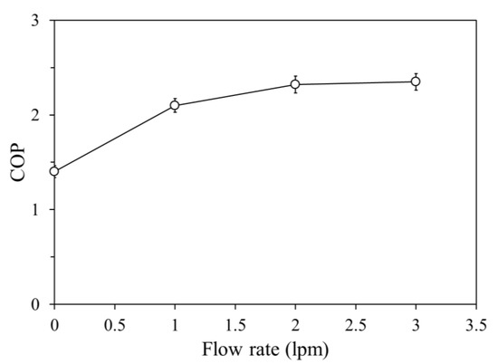
Figure 3.
COP of the water purifier cooling system according to the RO effluent flow rate for two condenser configurations.
Figure 4 shows the pressure trends as a function of the RO effluent flow rate in the high- and low-pressure sections of the refrigeration cycle. As heat transfer within the condenser increases, the condensing pressure decreases, leading to a decrease in compressor discharge pressure. This phenomenon has been widely reported in vapor compression systems, where improving condenser heat transfer efficiency effectively lowers the refrigerant saturation pressure and reduces compressor work input, thereby improving the overall system’s COP [25,26]. This decrease benefits compressor power consumption, further contributing to improved COP. However, the continued decrease in evaporating pressure due to this effect can reduce both the evaporating temperature and the refrigerant flow rate, potentially reducing cooling capacity. While this issue can be mitigated by optimizing the heat exchanger design and refrigerant charge, this study primarily focuses on evaluating the performance improvement achieved through drop-in replacement of a water-cooled condenser.
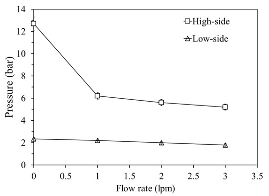
Figure 4.
Pressure trends as a function of the RO effluent flow rate in the high- and low-pressure sections of the refrigeration cycle.
3.2. Cooling Time
Figure 5 shows the water temperature reduction time in the water purifier cooling container using three configurations: a conventional air-cooled condenser and two water-cooled condenser modes with different RO discharge flow rates. In the air-cooled system, the water temperature decreased from 25 °C to 4 °C in approximately 120 min. However, when using a water-cooled condenser, the cooling time decreased significantly as the RO effluent increased. At the optimal flow rate of 1.5 LPM, the system reached the target temperature in just 94 min, achieving a time reduction of approximately 33%. This reduction in cooling time is beneficial in terms of shortening compressor operation time, reducing energy consumption, and increasing chilled water supply speed according to user demand. However, this trend reversed when the RO effluent flow rate exceeded 2 LPM. Specifically, at 2.5 LPM, the cooling time was longer than that of the air-cooled system.
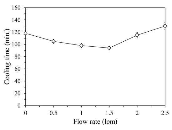
Figure 5.
Cooling time of water in the chamber according to the supply water flow rate.
As shown in Figure 5, this performance degradation is due to excessive frost formation on the evaporator surface as the evaporator temperature drops below −5 °C. While water begins to freeze when it reaches 0 °C, the heat exchange process requires a temperature differential of approximately 5 °C for frost formation [27,28]. This phenomenon is also evident in Figure 6 and Figure 7, showing that at high flow rates, the evaporator surface temperature decreases significantly, exacerbating frost formation. Frost acts as an insulating layer, reducing heat transfer efficiency between the refrigerant and the surrounding water. These results highlight the importance of limiting RO effluent flow in water-cooled systems. Under high flow conditions, system performance can be maintained or improved by optimizing the evaporator design and adjusting the refrigerant charge. In practice, in the cooling system, adjusting the capacity (area) of the evaporator heat exchanger or injecting an appropriate refrigerant charge is crucial, and during the cycle, limiting or controlling the RO effluent flow to near the observed optimum (1.5 LPM) and using a small temperature-controlled water bypass are required.
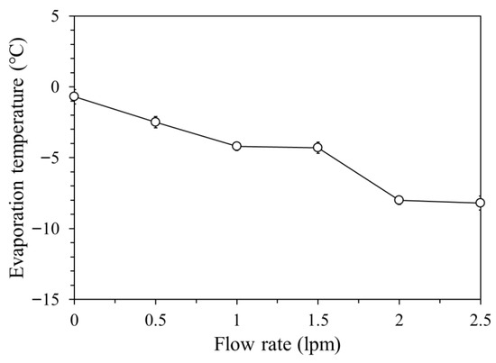
Figure 6.
Evaporation temperature according to the supply water flow rate.
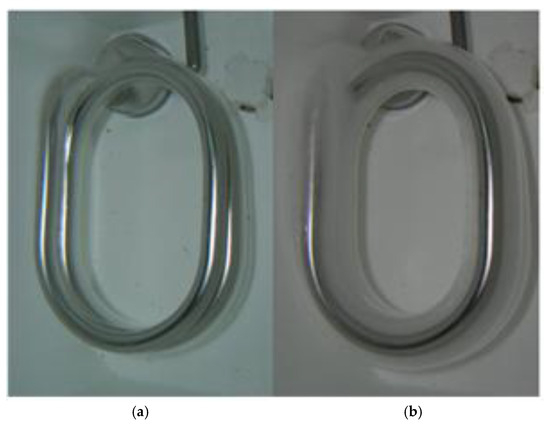
Figure 7.
Evaporator status in the water tank: (a) air-cooled and (b) water-cooled systems.
3.3. Intermittent RO Effluent Supply
During the filtration process in a water purification system, RO effluent is generated. In hot-and-cold water purifiers, the cooling cycle is activated when the water temperature in the storage tank rises. Two scenarios can be considered:
Case 1. Heat gain through insulation: Despite insulation, the tank temperature gradually rises over time due to heat transfer from the surrounding environment.
Case 2. Replenishment of used water: When cold water is used, purified water at room temperature is supplied to compensate for the reduced tank capacity. This incoming purified water is warmer than the stored water, thus increasing the overall tank temperature.
In case 2, the supply of purified water generates RO effluent, which can be continuously utilized as a cooling medium in the water-cooled condenser. Conversely, in the first case, no new RO effluent is generated, so the condenser uses the existing wastewater remaining in the chamber.
Figure 8 shows the changes in condenser outlet temperature and tank water temperature under two conditions: (1) with no circulating RO effluent (static), and (2) with an RO effluent flow rate of 1.5 LPM (flow). Without inlet effluent, the water in the cooling chamber gradually absorbs heat from the condenser, increasing its temperature. This reduces the condenser’s heat rejection rate and slightly slows the tank’s cooling rate. However, this performance degradation is not immediate. Due to water’s high specific heat capacity, stagnant RO effluent can act as an effective thermal buffer for short periods of time. Until the effluent temperature increases from 25 °C to 30 °C, the cooling behavior is very similar to that in circulating mode. The thermal inertia of stagnant water maintains a sufficient temperature gradient between the condenser surface and the surrounding medium, ensuring continuous heat rejection during short compressor cycles. Even in the stationary state, the tank temperature remains within 1 to 2 °C of the target temperature of 5 °C, indicating that the system can withstand brief interruptions in RO effluent flow without significant performance degradation. These results suggest that intermittent supply conditions, such as those that occur naturally during the idle filtration cycle, do not significantly impact system function, especially when combined with thermal design factors such as low-capacity compressor cycles and high-efficiency insulation.
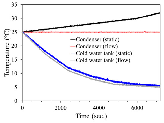
Figure 8.
Temperature variation under static and flow conditions.
3.4. Cooling Evaluation During Continuous Water Supply
Figure 9 shows the evolution of the tank water temperature under continuous water supply conditions. Both water-cooled and air-cooled condensers have a tank water temperature of approximately 4 °C when pull-down is complete. The numbers in parentheses in the legend indicate the water supply capacity. A certain amount of water is discharged every 30 min, and the corresponding amount is replaced with 25 °C water, immediately increasing the water temperature inside the tank. As the tank water temperature rises and the cooling system begins operating, the water-cooled condenser exhibits a rapid temperature drop due to its superior cooling performance. When 200 mL of water is supplied, after approximately six water supply and drain cycles, the air-cooled condenser maintained a temperature above 10 °C, while the water-cooled condenser maintained a temperature below 10 °C.
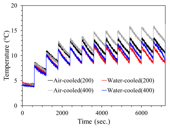
Figure 9.
Cooling performance during continuous water supply.
When the supply and drain volumes were increased to 400 mL, the temperature increase after each recharge became more pronounced as the amount of 25 °C inlet water increased. Furthermore, the final cooling temperature was also higher. This increased heat load negatively impacted the air-cooled system’s cooling performance, resulting in increased temperature fluctuations and decreased thermal stability. In contrast, the water-cooled condenser exhibited more consistent temperature control characteristics even with increased demand, even though the final water temperature was slightly higher at 200 mL These results suggest that while both systems can initially meet the cooling demand, the water-cooled system maintains its performance better under dynamic, high-load conditions. Rapid heat recovery helps maintain a stable chilled water supply and reduces compressor runtime and energy consumption during extended or frequent use. This suggests that water-cooled condenser integration may be particularly useful in real-world situations where water usage is intermittent but frequent, such as offices or multi-user homes.
3.5. Energy Consumption
Figure 10 shows power consumption over time under conditions where water supply and drainage occur every 30 min. For the first 30 min, the compressor operates in pull-down mode, reaching the set temperature and stopping. Power consumption is almost zero due to standby power. As water at 25 °C is supplied through drainage, the water temperature inside the tank rises, starting the compressor. Following this, power consumption immediately peaks to approximately 80 W for the air-cooled system and 70 W for the water-cooled system due to startup load. However, after about a minute, power consumption stabilized at approximately 66.7 W and 53.2 W, respectively, representing a decrease of approximately 20.2% in the water-cooled system. This is because the condensing pressure decreases when the condenser heat source is switched from air-cooled to water-cooled, lowering the compressor discharge pressure and reducing the compressor load. Similarly, in the air-cooled system, power consumption increases momentarily every 30 min when the water source is supplied, as shown in Figure 9. However, this phenomenon is rarely observed in the water-cooled system. In air-cooled systems, this indicates that the cycle responds sensitively to changes in evaporator temperature.
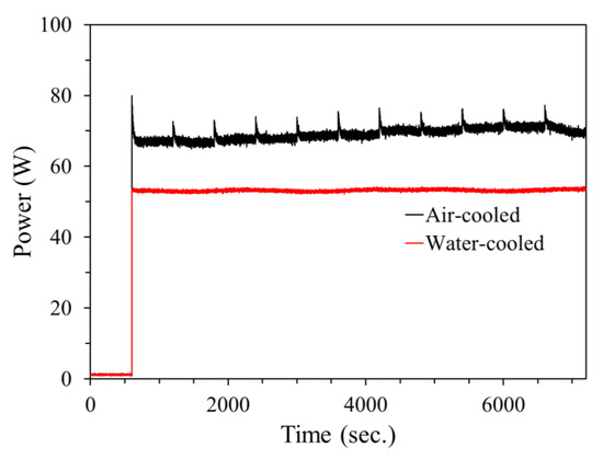
Figure 10.
Power consumption over time under periodic water supply and drainage (every 30 min).
Figure 11 compares the energy required for two condenser configurations in two representative operating modes. During pull-down operation, the water-cooled configuration reduces total energy consumption by 37.5% compared to the air-cooled baseline. This reduction is due to the lower condensing pressure and shorter compressor duty cycle needed to reach the setpoint, which reduces the time-integrated power requirement. To simulate frequent water usage that requires continuous compressor operation, a 24 h continuous operation evaluation showed that the water-cooled system reduced energy consumption by 20.2% compared to the air-cooled system. While the relative advantage is smaller than in pull-down mode, the absolute savings are significant because the compressor continues to operate once water supply and drainage are initiated. In practice, domestic hot-and-cold water purifiers operate in a combination of these two modes, depending on user behavior. Importantly, both modes demonstrate significant energy savings when using RO effluent as a condenser heat sink. This highlights the practical value of the proposed approach.
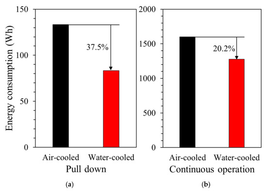
Figure 11.
Energy consumption of air-cooled and water-cooled condenser systems under two operation modes: (a) pull-down and (b) 24 h continuous operation.
4. Conclusions
This study presents a novel approach for integrating reverse osmosis (RO) effluent as a heat-rejecting medium into a water-cooled condenser system in a residential hot-and-cold water purifier. The proposed configuration was experimentally validated under controlled laboratory conditions and compared against a conventional air-cooled system.
- (1)
- During pull-down operation, where the system cools water from ambient to a target temperature, the water-cooled system reduced the cooling time by 33% and energy consumption by 37.5% compared to the air-cooled configuration.
- (2)
- Under 24 h continuous operation simulating frequent user interaction, the water-cooled system achieved an average energy saving of 20.2% due to reduced compressor power consumption resulting from lower condensing pressure.
- (3)
- Performance was maintained consistently even under intermittent RO effluent supply conditions, with minimal cooling performance degradation and no compressor cycling beyond normal standby operation.
- (4)
- Excessive RO effluent flow rates (exceeding 2.0 LPM) resulted in evaporator freezing, reducing thermal efficiency. However, performance remained optimal at 1.5 LPM, suggesting that flow control is crucial for maximizing system performance.
These results demonstrate that using internally generated RO effluent as a cooling medium can significantly improve the energy efficiency, thermal performance, and design miniaturization of domestic water purification systems. Furthermore, this approach enables device-integrated reuse of RO effluent, addressing one of the major environmental challenges facing modern domestic water purification technology. Future research should explore long-term fouling behavior, optimal refrigerant charge adjustment, and the potential for widespread application in multi-stage cooling structures. This study was conducted on a laboratory-scale prototype under controlled conditions, and the absolute savings may vary in actual field applications. Long-term fouling and scaling of heat exchange surfaces, variations in RO effluent availability and pressure due to user behavior, and installation and regulatory constraints (e.g., piping interfaces and backflow prevention) can all impact durability and performance in large-scale installations. These considerations limit the scope of generalization beyond the current setup and motivate future field validation and maintainability design studies.
Funding
This work was supported by the National Research Foundation of Korea (NRF) grant funded by the Korea government (MSIT) (RS-2025-00523335) and the Commercialization Promotion Agency for R&D Outcomes (COMPA) funded by the Ministry of Science and ICT (MSIT) (RS-2025-25416427, University Technology Management Promotion Project (TLO Innovation Type)_NATIONAL KOREA MARITIME & OCEAN UNIVERSITY).
Data Availability Statement
Data is contained within the article.
Acknowledgments
During the preparation of this manuscript, the author used ChatGPT-4o for assistance with manuscript structuring, language refinement, and translation. The author has thoroughly reviewed and edited all AI-generated content and assumes full responsibility for the final version of the manuscript.
Conflicts of Interest
The authors declare no conflicts of interest.
Abbreviations
| COP | Coefficient of performance |
| LPM | Liter per minute |
| RO | Reverse osmosis |
| SV | Solenoid valve |
References
- United Nations Children’s Fund (UNICEF); World Health Organization (WHO). Progress on Household Drinking Water, Sanitation and Hygiene 2000–2022: Special Focus on Gender; World Health Organization: Geneva, Switzerland, 2024. [Google Scholar]
- World Health Organization (WHO). Strong Systems and Sound Investments: Evidence on and Key Insights into Accelerating Progress on Sanitation, Drinking-Water and Hygiene: UN-Water Global Analysis and Assessment of Sanitation and Drinking-Water (GLAAS) 2022 Report; World Health Organization: Geneva, Switzerland, 2023. [Google Scholar]
- Doria, M.F. Factors Influencing Public Perception of Drinking Water Quality. Water Policy 2010, 12, 1–19. [Google Scholar] [CrossRef]
- Peter-Varbanets, M.; Zurbrügg, C.; Swartz, C.; Pronk, W. Decentralized Systems for Potable Water and the Potential of Membrane Technology. Water Res. 2009, 43, 245–265. [Google Scholar] [CrossRef] [PubMed]
- Bain, R.; Cronk, R.; Hossain, R.; Bonjour, S.; Onda, K.; Wright, J.; Bartram, J. Global Assessment of Exposure to Faecal Contamination through Drinking Water Based on a Systematic Review. Trop. Med. Int. Health 2014, 19, 917–927. [Google Scholar] [CrossRef]
- Kapepula, V.L.; Luis, P. Removal of heavy metals from wastewater using reverse osmosis. Front. Chem. Eng. 2024, 6, 1334816. [Google Scholar] [CrossRef]
- Yang, Z.; Zhou, Y.; Feng, Z.; Rui, X.; Zhang, T.; Zhang, Z. A review on reverse osmosis and nanofiltration membranes for water purification. Polymers 2019, 11, 1252. [Google Scholar] [CrossRef]
- García-Ávila, F.; Zambrano-Jaramillo, A.; Velecela-Garay, C.; Coronel-Sánchez, K.; Valdiviezo-Gonzales, L. Effectiveness of membrane technologies in removing emerging contaminants from wastewater: Reverse Osmosis and Nanofiltration. Water Cycle 2025, 6, 357–373. [Google Scholar] [CrossRef]
- Shabib, A.; Tatan, B.; Elbaz, Y.; Hassan, A.A.; Hamouda, M.A.; Maraqa, M.A. Advancements in reverse osmosis desalination: Technology, environment, economy, and bibliometric insights. Desalination 2024, 585, 118413. [Google Scholar] [CrossRef]
- Monachan, M.; Dixit, N.; Maliyekkal, S.M.; Singh, S.P. Reverse osmosis (RO) and nanofiltration (NF) membranes for emerging contaminants (ECs) removal. In New Trends in Emerging Environmental Contaminants; Springer: Singapore, 2021; pp. 407–425. [Google Scholar]
- AL-Musawi, O.A.; Mohammad, A.W.; Mahood, H.B.; Ang, W.L.; Mahmoudi, E.; Kadhum, A.A.H. Generating osmotic power using waste effluents for pressure-retarded osmosis. Arab. J. Sci. Eng. 2025, 50, 4295–4311. [Google Scholar] [CrossRef]
- Jijingi, H.E.; Yazdi, S.K.; Abakar, Y.A.; Etim, E. Evaluation of membrane bioreactor (MBR) technology for industrial wastewater treatment and its application in developing countries: A review. Case Stud. Chem. Environ. Eng. 2024, 10, 100886. [Google Scholar] [CrossRef]
- Ullah, M.N.; Mushtaq, M.U.; Adil, M.A.; Sanaullah, K.; Ashas, R.; Sabir, R. Application of UF and RO for power plant’s wastewater treatment and recycling for environmental sustainability. J. Water Clim. Change 2023, 14, 1991–2006. [Google Scholar] [CrossRef]
- Reynaert, E.; Greenwood, E.E.; Ndwandwe, B.; Riechmann, M.E.; Sindall, R.C.; Udert, K.M.; Morgenroth, E. Practical implementation of true on-site water recycling systems for hand washing and toilet flushing. Water Res. X 2020, 7, 100051. [Google Scholar] [CrossRef]
- Ahmed, J.; Jamal, Y.; Shujaatullah, M. Recovery of cooling tower blowdown water through reverse osmosis (RO): Review of water parameters affecting membrane fouling and pretreatment schemes. Desalination Water Treat. 2020, 189, 9–17. [Google Scholar] [CrossRef]
- Ho, J.Y.; Leong, K.C. A critical review of filmwise natural and forced convection condensation on enhanced surfaces. Appl. Therm. Eng. 2021, 186, 116437. [Google Scholar] [CrossRef]
- Kamma, P.; Loksupapaiboon, K.; Phromjan, J.; Promtong, M.; Suvanjumrat, C. Optimization of plate-fin heat sink configurations for enhanced thermal performance and manufacturability. Case Stud. Therm. Eng. 2025, 41, 106529. [Google Scholar] [CrossRef]
- Zhang, H.; Feng, X.; Wang, Y. Comparison and evaluation of air cooling and water cooling in resource consumption and economic performance. Energy 2018, 154, 157–167. [Google Scholar] [CrossRef]
- Li, W.; Zhang, G.; Yang, D. Comparative study for flow condensation heat transfer in horizontal enhanced tubes based on machine learning. Int. J. Heat Mass Transf. 2024, 224, 125330. [Google Scholar] [CrossRef]
- Chen, Y.; Wang, H.; Liu, X.; Zhang, J. Simulation Research on the Optimization of Domestic Heat Pump Water Heater Using Fin-Tube Condenser. Energies 2023, 16, 7441. [Google Scholar]
- Alrashidi, H.; Alotaibi, A. Utilizing a Domestic Water Tank to Make the Air Conditioning System in Residential Buildings More Efficient by Replacing an Air-Cooled Condenser with a Water-Cooled Arrangement. Sustainability 2025, 17, 75. [Google Scholar]
- Kim, D.; Lee, S.; Park, S.H. Performance Evaluation of a Domestic Reverse Osmosis Water Purifier with Multi-Stage Filtration: Effects of Pre-Carbon and Post-Carbon Filters. Energies 2022, 15, 5208. [Google Scholar]
- KS C IEC 60335-2-24; Household and Similar Electrical Appliances—Safety—Particular Requirements for Refrigerating Appliances, Ice-Cream Appliances and Ice-Makers. Ministry of Trade, Industry and Energy: Seoul, Republic of Korea, 2020.
- Zaki, O.M.; Stavins, R.A.; Wenzel, M.; Musser, A.; Sharar, D.; Elbel, S.; King, W.P. Additively Manufactured Compact Water-Cooled Refrigerant Condenser. Int. J. Heat Mass Transf. 2025, 244, 126836. [Google Scholar] [CrossRef]
- Naik, B.K.; Muthukumar, P. Empirical Correlation Based Models for Estimation of Air-Cooled and Water-Cooled Condenser’s Performance. Energy Procedia 2017, 109, 293–305. [Google Scholar] [CrossRef]
- Pottker, G.; Hrnjak, P. Experimental Investigation of the Effect of Condenser Subcooling in R134a and R1234yf Air-Conditioning Systems with and without Internal Heat Exchanger. Int. J. Refrig. 2015, 50, 104–113. [Google Scholar] [CrossRef]
- Krasota, D.; Błasiak, P.; Kolasiński, P. Literature Review of Frost Formation Phenomena on Domestic Refrigerators Evaporators. Energies 2023, 16, 2945. [Google Scholar] [CrossRef]
- Carvajal-Mariscal, I.; De León-Ruiz, J.E.; Belman-Flores, J.M.; Martínez-Espinosa, E.; José-Pineda, O. Experimental Assessment and Semi Empirical Estimation of Frost Accretion—A Case Study on a Spine-Finned Inverted-V Tube Array Evaporator. Front. Mech. Eng. 2023, 9, 1101425. [Google Scholar] [CrossRef]
Disclaimer/Publisher’s Note: The statements, opinions and data contained in all publications are solely those of the individual author(s) and contributor(s) and not of MDPI and/or the editor(s). MDPI and/or the editor(s) disclaim responsibility for any injury to people or property resulting from any ideas, methods, instructions or products referred to in the content. |
© 2025 by the author. Licensee MDPI, Basel, Switzerland. This article is an open access article distributed under the terms and conditions of the Creative Commons Attribution (CC BY) license (https://creativecommons.org/licenses/by/4.0/).