Article

Multi-Parameter Synchronous Identification Method for Dual Metal Rubber Clamps Considering Directional Differences in Mechanical Properties

1
School of Mechanical Engineering and Automation, Northeastern University, Shenyang 110819, China
2
Key Laboratory of Vibration and Control of Aerodynamic Equipment, Ministry of Education, Northeastern University, Shenyang 110819, China
*
Author to whom correspondence should be addressed.
Appl. Sci. 2025, 15(20), 11239; https://doi.org/10.3390/app152011239 (registering DOI)
Submission received: 15 September 2025 / Revised: 13 October 2025 / Accepted: 16 October 2025 / Published: 20 October 2025

Abstract

Featured Application

This identification method can be used for parameter identification of dual metal rubber clamps (DMRCs) in aero-engines, providing mechanical parameters of the clamps for dynamic simulation work of pipeline systems. It is expected to be applied in the optimal design of aero-engine pipeline systems.

Abstract

Due to structural characteristics and connection dimensions, the dynamic characteristics of dual metal rubber clamps (DMRCs) show significant differences in bolt connection direction and opening direction. Accurately identifying the dynamic parameters of DMRC in different directions is of great significance for analyzing the dynamic characteristics and vibration control of aero-engine piping systems. This paper takes a DMRC-double straight pipe structure as the research object and establishes a dynamic model of this structure based on the finite element method as the mechanical parameter identification model of DMRCs. A refined simulation mechanism is adopted in the model to reflect the dynamic characteristics of the DMRC. The DMRC is simplified into four concentrated mass blocks and four spring-damping groups to simulate its mass, stiffness, and damping effects. Each spring-damping group consists of a linear spring, a rotational spring, and a damper. The four groups of springs are further divided into two directional groups to simulate the stiffness and damping effects in the opening direction and bolt connection direction, respectively. Four concentrated mass blocks are applied to the four nodes of the pipe to simulate the mass effect of DMRCs. Based on the dynamic model of the pipeline structure mentioned above, the synchronous identification algorithms and procedures for multiple mechanical parameters of DMRCs are proposed, aiming to minimize the deviation of natural characteristic indicators (natural frequency and peak of frequency response function) obtained through testing and model simulation. This method can synchronously identify linear stiffness, rotational stiffness, and damping in different directions. Finally, the effectiveness of the identification method is verified through experiments.

1. Introduction

The pipeline system of aero-engines can generate complex vibrations under the combined excitation of multiple loads, and prolonged excessive vibrations can lead to premature fatigue failure of the pipe [1,2,3]. Metal rubber clamps are important pipe connection and support components, and their mechanical properties seriously affect the vibration characteristics of the pipe systems [4,5,6]. Compared to other types of clamps, dual metal rubber clamps (DMRCs) are mainly used to connect parallel pipelines (the diameters of the two pipelines may be different), and the proportion of DMRCs in quantity is relatively large (as shown in Figure 1). Therefore, the mechanical properties of a DMRC have a great impact on the dynamic characteristics of the pipeline system. In order to accurately analyze the structural dynamics, vibration characteristics, vibration reduction optimization, and fault diagnosis of pipeline systems, it is particularly important to accurately obtain the mechanical performance parameters of DMRCs.
As a composite connection structure that uses bolt pre-tightening force to generate a clamping effect, the DMRC provides three directions of support and damping effect to the pipe in the clamping state. As shown in Figure 2, the three directions are the radial, axial, and circumferential directions of the pipe, and the support and damping effects in the three directions play a dominant role in the radial, axial, and circumferential torsional vibration of the pipe. Among them, the radial support effect and radial damping effect have their own uniqueness. The structure of the DMRC in the circumferential direction of the pipe is not circularly symmetrical, which leads to significant asymmetry or circumferential structural nonlinearity in the radial mechanical characteristics of the clamp in the circumferential direction of the pipe. Notably, the difference between the direction of the bolt connection ( y or y 1 direction) and the direction of the opening ( x or x 1 direction) is most obvious (as shown in Figure 2). When the pipe vibrates in different radial directions, the clamp will provide significantly different support stiffness and damping. Therefore, the mechanical properties of the DMRC reflect complex multidirectional and asymmetric characteristics. Therefore, the key prerequisite for identifying the mechanical parameters of DMRCs is to establish a parameter identification model that can efficiently, conveniently, and accurately characterize the mechanical properties of DMRCs (anisotropic stiffness and damping).
At present, research related to the dynamics of metal rubber clamps has been carried out, mostly targeting single metal rubber clamps (SMRCs). For the dynamic study of pipeline systems, scholars have used analytical methods [7,8,9,10], semi-analytical methods [11,12,13,14], transfer matrix methods [15] (as well as a combination of semi-analytical and transfer matrix methods [16]), and finite element methods [17,18,19,20,21] for research. In these studies, the support stiffness and damping effects of SMRCs were simulated using a spring-damping module. The simulation method was also developed. Initially, a simplified equivalent simulation using a single spring-damping module was adopted. Currently, multiple spring-damping modules are used for differentiated simulation in multiple directions. Even some scholars had arranged springs in the circumferential direction of the pipe to simulate the connection effect of the clamp [22]. Meanwhile, in the finite element method, some scholars used the high-fidelity model of clamps to simulate the connection effect of clamps more accurately [23,24]. Based on the modeling methods of the above clamp connection effects, some research on clamp connection optimization had also been carried out [25,26,27,28,29,30]. However, due to the differences in structure between DMRCs and SMRCs, there are different mechanical boundary conditions (SMRCs are bolted to the aero-engine casing, while DMRCs are not connected to the casing). Therefore, some scholars conducted dynamic modeling research on DMRCs based on the dynamic research of SMRCs; for example, Chen et al. [31] introduced a new semi-analytical dynamic model that effectively considers the influence of DMRCs in parallel pipeline systems. The Bouc–Wen model was used to simulate the vertical hysteresis recovery force of the clamp. Each DMRC was simplified into two sets of springs. Each group of springs was equivalent to two translation springs and two torsion springs in each direction. The stiffness and damping of each spring were half of the measured stiffness in that direction. Guo et al. [32] established a dynamic model of a series of parallel complex fluid transportation pipeline systems based on the improved transfer matrix method (ITMM). In ANSYS software (version: 19.1), the DMRC was equivalent to two sets of combin14 elements. Each group of combin14 elements contained translational and torsional stiffness in three directions. The springs are connected to corresponding nodes in two parallel pipelines. Gao et al. [33] considered the constraint interface stiffness of elastic support and fluid–structure coupling pipeline systems and obtained a new reduced-order model by assembling reduced-order substructure elements. The DMRC connected the parallel pipelines. The clamps were considered as linear springs and rotational springs. Although the above dynamic models, considering the connection effects of SMRCs and DMRCs, may not be fully applicable for the identification of dynamic parameters of DMRCs, they can provide a reference for the establishment of dynamic parameter identification models for DMRCs.
Some studies have also been conducted on the identification of dynamic parameters for clamps. In some studies, static tests were used to identify the mechanical parameters of clamps; for example, Chai et al. [34] designed testing equipment that can apply linear tensile and torsional loads to a SMRC. The equipment was used to identify the static linear stiffness and torsional stiffness of the clamp and can obtain the hysteresis curve of the clamp. A simplified bilinear stiffness and damping model was proposed based on identification results. Lin et al. [35] designed a static parameter testing system for single and double clamps. Based on the test results, the static stiffness and the hysteresis curve describing the nonlinear characteristics of the clamps were identified. However, in current static mechanics testing, a constant load is applied to the clamp, and the testing accuracy is greatly affected by the load application mechanism, transmission accuracy, and even the operator’s proficiency. Therefore, the static mechanical characteristic parameters of the clamp are identified through this method. Although these static mechanical characteristic parameters can serve as approximate reference values for the dynamic characteristics of clamps, they cannot accurately reflect the dynamic characteristics of clamps. For this reason, some scholars have conducted identification studies on the dynamic parameters of clamps based on dynamic testing; for example, Cao et al. [36] equated a SMRC to two sets of spring dampers along the axial direction of the pipe (each set of spring dampers consists of eight springs and four dampers) and proposed a four-degrees-of-freedom nonlinear clamp model. Based on the vibration response experimental data of a pipeline system fixed by SMRCs, a genetic algorithm-based nonlinear parameter identification method for SMRCs is proposed. Wang et al. [37] proposed an improved transfer matrix method to simulate the numerical stability dynamics of a multi-span fluid transport pipeline with multiple centralized attachments and flexible components, where the SMRC was simulated using two spring-damping groups (one translational direction and one rotational direction). Based on this model, a SMRC stiffness inversion method was proposed with the optimization objective of minimizing the difference between the measured natural frequency of the pipeline and the predicted natural frequency of the theoretical model. However, for DMRCs, Zhu et al. [38] used the Dynamic Stiffness Matrix method to establish a dynamic model of a dual pipe system with a DMRC. The DMRC was simplified into a mass block and a composite spring. The composite spring includes the angular stiffness and linear stiffness of the DMRC. Based on this model, an approximate function of the theoretical frequency and experimental frequency of the DMRC was established, and a dynamic identification method for the stiffness of the DMRC based on system mode was proposed.
Through the above literature research, it has been found that the dynamic characteristics of metal rubber clamps have attracted much attention in the study of the dynamics of aero-engine piping systems. Compared with the identification method of mechanical parameters of clamps based on static loading experiments, the identification method based on dynamic testing is more reliable. However, there is currently little research on the identification of mechanical parameters of clamps based on dynamic testing. For DMRCs, research on mechanical parameter identification based on dynamic testing is even rarer. In the existing research on mechanical parameter identification of DMRCs, only the stiffness parameters are considered, and the influences of the structural size parameters of the clamp (such as width, pipe diameter, etc.) on its dynamic characteristics are not taken into account. Therefore, in response to the above issues, the innovations of this paper are that a refined discrete model of dual metal rubber clamps (DMRCs) considering directional differences is proposed, which achieves the differentiated characterization of mechanical properties between the bolt connection direction and the opening direction, and a multi-parameter synchronous identification framework based on the Pareto multi-objective genetic algorithm is constructed, realizing the integrated identification of linear stiffness, rotational stiffness, and damping of DMRCs. This study takes a parallel straight pipe structure with complete constraints at both ends as the research object, and two straight pipes are connected by a DMRC (as shown in Figure 3). As can be seen from the figure, both sides of the pipe body are fixed by fixtures, simulating that both ends of the pipe body are completely constrained; that is, the six degrees of freedom are completely restricted. This structure can more accurately reflect the working state of the DMRCs in the aero-engine piping system. A dynamic model of the parallel straight pipe structure is established using the finite element method. Due to the differences in the dynamic characteristics of DMRCs in different directions, and the fact that the width variation of DMRCs can also affect the dynamic behavior of pipeline systems, this study proposes a refined simulation mechanism to reflect the dynamic characteristics of DMRCs. The DMRC is simplified into four concentrated mass blocks and four spring-damping groups to simulate its mass, stiffness, and damping effects. Each spring group consists of a linear spring, a rotating spring, and a damper. The four groups of springs are further divided into two groups to simulate the stiffness and damping effects in the opening direction and bolt connection direction, respectively. Four concentrated mass blocks are applied to the four nodes of the pipe to simulate the mass effect of DMRCs. Based on the dynamic model of the pipeline structure mentioned above, a synchronous identification method for multiple mechanical parameters of DMRCs is proposed, which aims to minimize the deviation of natural characteristic indicators (natural frequency and peak of frequency response function) through experimental testing and model simulation. Compared with the previous CMRC mechanical parameter identification methods, the advantages of this method are as follows: it accurately adapts to the directional mechanical characteristics of DMRC and solves the “asymmetry” identification problem; it realizes the simultaneous identification of multiple parameters, covering two types of parameters, i.e., stiffness and damping; and it is based on the Pareto multi-objective genetic algorithm, which ensures the global optimality of identification.
The organization of this paper is as follows: The dynamic model of the simplified DMRC-pipeline structure is introduced in Section 2. In Section 3, the identification algorithm and procedure for the dynamic parameters of the DMRC are elaborated. In Section 4, the effectiveness of the identification method proposed in this paper is verified through experiments. Finally, some important conclusions are listed in Section 5.

2. Dynamic Parameter Identification Model

In order to identify the anisotropic dynamic parameters of the DMRC, it is necessary to establish a structure that can reflect the mechanical characteristics of the clamp in different directions. A DMRC-double straight pipe system is used to study the mechanical parameter identification method of DMRCs in this paper. As shown in Figure 3, two straight steel pipes are arranged in parallel, and a DMRC is used to connect the two straight pipes in the middle position. The two ends of the straight pipes are fixed and connected by the fixture. A dynamic FEM of this structure is established as the mechanical parameter identification model for the DMRC. The model is established through three steps. Firstly, a mechanical constitutive model of the DMRC is established. Due to the DMRC providing support and damping for the pipeline system, a spring-damping module is used to establish the mechanical constitutive model. Next, a FEM of the straight pipe is established. Considering that beam elements can simulate bending, tension/compression, and torsion effects, and can effectively simulate the mechanical characteristics of slender components, a FEM of the pipe is established using beam elements. Finally, the mechanical constitutive model of the DMRC is combined with the FEM of the pipe. After establishing the dynamic FEM of the DMRC-double straight pipe system, the frequency response function of the system is solved.

2.1. Dynamic Constitutive Model for the Connection Between DMRC and Pipe

The constitutive model of the DMRC is shown in Figure 4. The DMRC is equivalently discretized into two sets of linear spring-damping models along the z direction. Each set of spring-damping models includes a x direction stiffness spring, a corner stiffness spring, and a x direction damping coefficient (without considering the rotation damping coefficient), where the stiffness value and damping value are half of the overall stiffness and damping in the x direction of the clamp, respectively. Simultaneously, considering the concentrated mass effect of the clamp, the overall mass is equivalent to four mass points and applied to the nodes connected to the spring-damping model and the pipe.
Assuming that the i -th node of the DMRC is connected to the j -th node of the pipe, due to the relative motion between the two nodes at the connection position, the coupling forces acting on the clamp Δ F i and the pipe Δ F j can be expressed as Equation (1).
Δ F i = K coup x i + C coup x ¯ i K coup x j C coup x ¯ j Δ F j = K coup x j + C coup x ¯ j K coup x i C coup x ¯ i
where K coup and C coup are the coupling stiffness and damping between the clamp and the pipe, x i , x ¯ i are the displacement and velocity of i -th node of the clamp, and x j , x ¯ j are the displacement and velocity of j -th node of the pipe. The stiffness matrix K c and damping matrix C c between each pair of nodes in relative motion are, respectively, represented as follows:
K c = i j K coup K coup K coup K coup i j
C c = i j C coup C coup C coup C coup i j
The stiffness matrix K cl and damping matrix C cl of the clamp corresponding to the constitutive model constructed in Figure 4 are shown in Equations (4) and (5).
K cl = k x k y 0 k r x k r y 0
C cl = c x c y 0 0 0 0
Combining Equations (2)–(5), the stiffness matrix K c - p and damping matrix C c - p of the joint between the clamp and the pipe can be obtained as follows:
K c - p = K cl K cl K cl K cl
C c - p = C cl C cl C cl C cl

2.2. FEM of the Pipe

The axial translational and torsional deformations of the pipe are ignored, and Timoshenko beam elements are used for dynamic modeling. As shown in Figure 5, the coordinate system of a certain pipe element is o x y z , and l n is the length of the n -th pipe element. The displacement vector of the j -th node and ( j + 1 ) -th node can be expressed as follows [17]:
h n = u j , v j , φ j , θ j , u j + 1 , v j + 1 , φ j + 1 , θ j + 1
The stiffness matrix (symmetric matrix) of the pipe element can be expressed as follows [19]:
K n = E A l n 0 12 E I y l n 3 1 + b x 0 0 12 E I x l n 3 1 + b y 0 0 0 G I P l n 0 0 6 E I x l n 2 1 + b y 0 4 + b y E I x l n 3 1 + b y 0 6 E I y l n 2 1 + b x 0 0 0 4 + b x E I y l n 3 1 + b x E A l n 0 0 0 0 0 E A l n 0 12 E I y l n 3 1 + b x 0 0 0 6 E I y l n 2 1 + b x 0 12 E I y l n 3 1 + b x 0 0 12 E I x l n 3 1 + b y 0 6 E I x l n 2 1 + b y 0 0 0 12 E I x l n 3 1 + b y 0 0 0 G I P l n 0 0 0 0 0 G I P l n 0 0 6 E I x l n 2 1 + b y 0 2 b y E I x l n 1 + b y 0 0 0 6 E I x l n 2 1 + b y 0 4 + b y E I x l n 3 1 + b y 0 6 E I y l n 2 1 + b x 0 0 0 2 b x E I y l n 1 + b x 0 6 E I y l n 2 1 + b x 0 0 0 4 + b x E I y l n 3 1 + b x
where K n is a symmetric matrix, I x and I y are the principal moments of inertia for the x -axis and y -axis, b x and b y are the shear influence coefficients for the x -axis and y -axis, E is Young’s modulus, A is the cross-sectional area of the pipe, G is the shear modulus, and I P is the torsional moment of inertia for the z -axis.
The mass matrix (symmetric matrix) of the pipe unit can be expressed as follows [19]:
M n = ρ A l n 1 3 0 A y 0 0 A x 0 0 0 I P 3 A 0 0 C x 0 E x 0 C y 0 0 0 E y 1 6 0 0 0 0 0 1 3 0 B y 0 0 0 D y 0 A y 0 0 B x 0 D x 0 0 0 A x 0 0 0 I P 6 A 0 0 0 0 0 I P 3 A 0 0 D x 0 F x 0 0 0 C x 0 E x 0 D y 0 0 0 F y 0 C y 0 0 0 E y
where r x = I x / A , r y = I y / A , r x , and r y are the radius of rotation around the x -axis and y -axis, and ρ is the material density. In addition, for A y = A r y , b x , A x = A r x , b y , B y = B r y , b x , …, F y = F r y , b x , F x = F r x , b y , their general expressions are as follows:
A r , b = 13 35 + 7 10 b + 1 3 b 2 + 6 5 r l n 2 1 + b 2
B r , b = 9 70 + 3 10 b + 1 6 b 2 6 5 r l n 2 1 + b 2
C r , b = 11 210 + 11 120 b + 1 24 b 2 + 1 10 1 2 b r l n 2 l n 1 + b 2
D r , b = 3 420 + 3 40 b + 1 24 b 2 1 10 1 2 b r l n 2 l n 1 + b 2
E r , b = 1 105 + 1 60 b + 1 120 b 2 2 15 + 1 6 b + 1 3 b 2 r l n 2 l n 2 1 + b 2
F r , b = 1 140 + 1 60 b + 1 120 b 2 + 1 30 + 1 6 b + 1 6 b 2 r l n 2 l n 2 1 + b 2

2.3. FEM of DMRC-Pipeline System

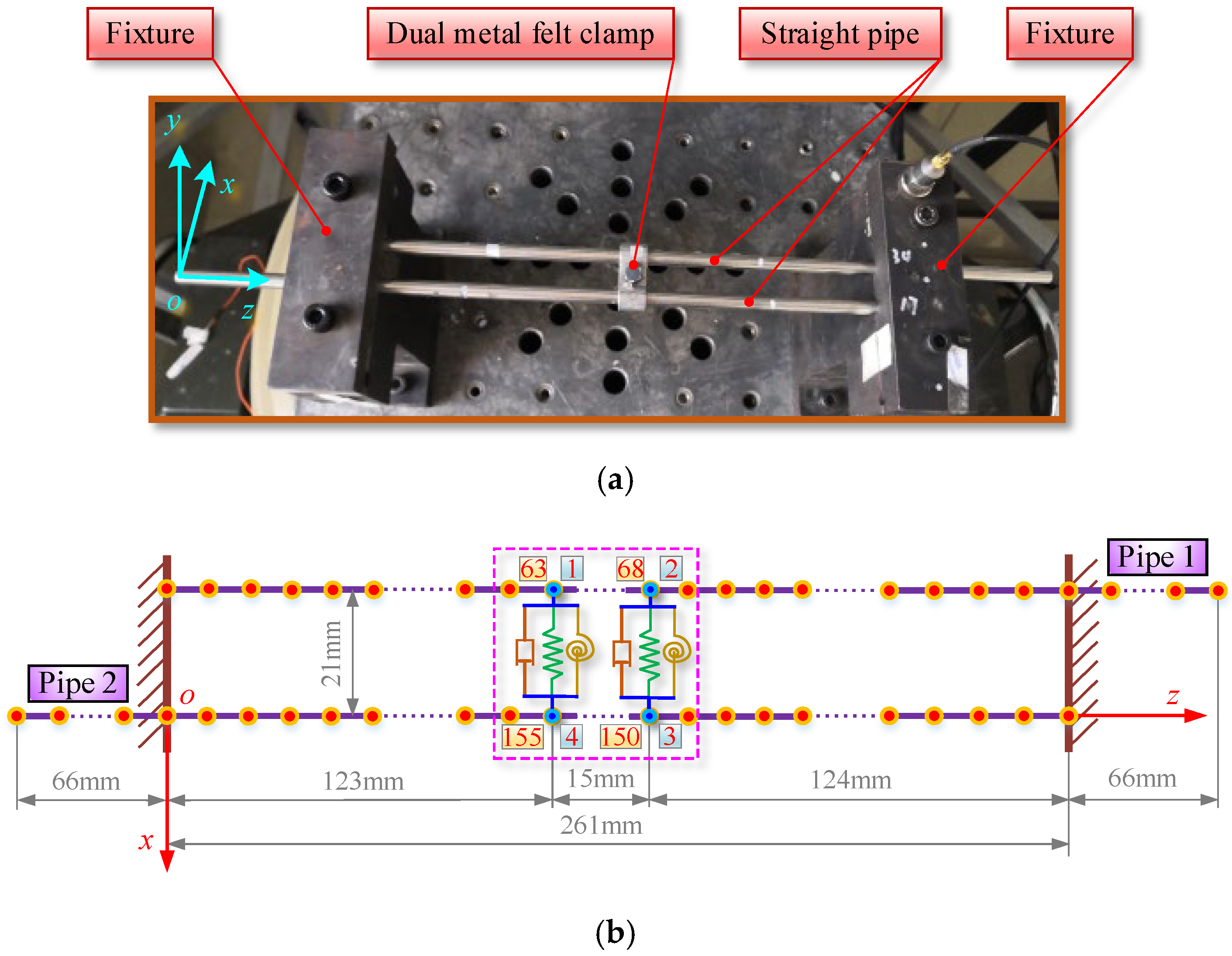
In order to provide a detailed introduction to the finite element modeling process of the DMRC-pipeline system, the modeling method is elaborated based on the experimental structure of this paper. As shown in Figure 6a, two straight pipes are clamped in parallel and staggered on the fixture. The material and structural parameters of the pipe are listed in Table 1. The parallel distance between two straight pipes is 21 mm. The total length of the pipe is 403 mm. After removing the fixed parts at both ends of the pipe, its effective length is 327 mm. Two straight pipes are connected through a DMRC at the middle position of the two fixtures (clamp model: SK8-8, clamp width: 15 mm). The FEM of this structure is shown in Figure 6b. Firstly, based on the pipe element in Section 2.2, the two straight pipes are discretized, and the length of the pipe element is defined as 3 mm. Each pipe is divided into 109 elements, and the two pipes are divided into a total of 218 elements. Then, the equivalent model of the clamp in Section 2.1 is added to the FEM of the two straight pipes, and the four nodes of the clamp model are connected to nodes 63, 68, 150, and 155 of the two straight pipes, respectively.
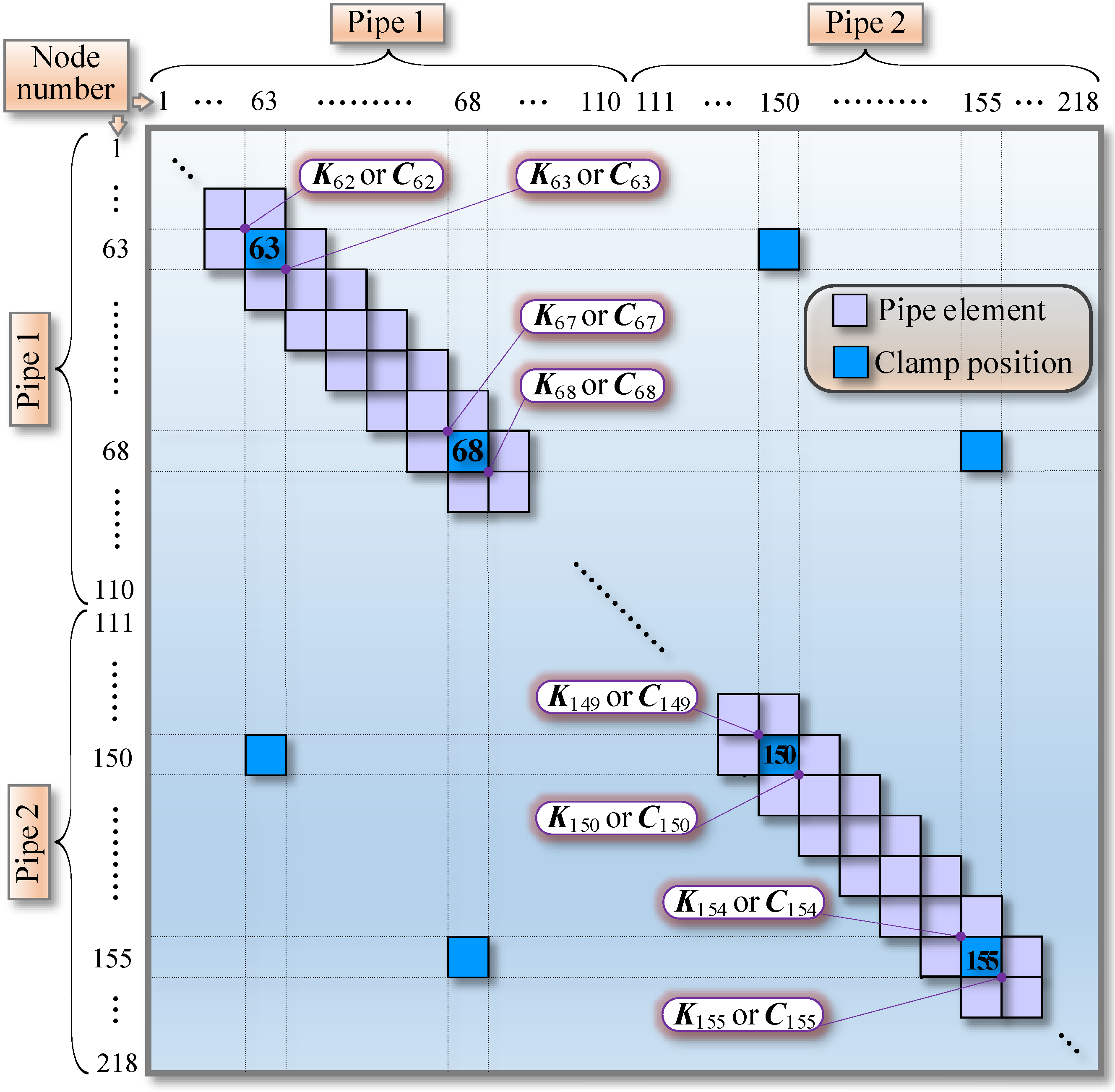
The stiffness matrix K p and the damping matrix C p of the whole pipe can be obtained by superimposing the stiffness, damping, and mass matrices of adjacent tube elements. Then, the stiffness matrix K and the damping matrix C of the DMRC-pipeline system can be expressed as Equations (17) and (18), and the set formula is shown in Figure 7. Meanwhile, the mass matrix M of the DMRC-pipeline system can be obtained by attaching a concentrated mass of clamps at the corresponding positions of the pipe mass matrix M p , which can be expressed as Equation (19).
K = K p + K c l
C = C p + C cl
M = M p + M cl
Next, the dynamic equation of the DMRC-pipeline system can be obtained as follows:
M X ¨ + C X ˙ + K X = F
where X ¨ , X ˙ , and X are the acceleration, velocity, and displacement response vectors of the DMRC-pipeline system, respectively.
In Equation (10), the stiffness K is composed of the clamp stiffness K cl and the pipe stiffness K p , where the clamp stiffness K cl is the identification object. The damping C of the system consists of clamp damping C cl and pipe damping C p , where clamp damping C cl is the identification object. Herein, the pipe damping is simulated using Rayleigh damping; that is, C p = α M + β K . Among them, α and β are the Rayleigh damping coefficients, which can be obtained from Equations (21) and (22).
α = 2 ω κ ω τ ζ κ ω τ ζ τ ω κ ω τ 2 ω κ 2
β = 2 ζ τ ω τ ζ κ ω κ ω τ 2 ω κ 2
where ζ κ and ζ τ are the structure damping ratios of the κ -th and τ -th order, ω κ and ω τ are the natural circular frequencies of the κ -th and τ -th orders ( rad / s ). Here, the values of κ and τ are determined by the minimum and maximum values of the order range of interest.
The acceleration frequency response function (FRF) required for identifying clamp damping is as follows:
H ω = r = 1 R ω 2 Ψ r Ψ r T ω r 2 + 2 i ζ r ω r ω ω 2
where ω is the external excitation frequency, ω r is the system natural frequency of the r -th order, ζ r is the system modal damping ratio of the r -th order, R is the calculated total number of modes, and Ψ r is the vibration shape vector of the r -th order.

3. Algorithm and Procedure for Identifying Mechanical Parameters of Clamps

3.1. Identification Algorithm

In this study, the Pareto multi-objective genetic algorithm, which can achieve multi-objective optimization, is used to identify the mechanical parameters of the clamp. The general optimization principle of this algorithm is as follows:
min f 1 ( ϑ ) , f 2 ( ϑ ) , , f φ ( ϑ )
s . t l ϕ ϑ u ϕ ϖ e q ϑ = ϕ e q ϖ ϑ ϕ
where f φ ( ϑ ) is the φ -th optimization objective function and ϑ is the optimization variable. In the constraint conditions, l ϕ and u ϕ are the upper and lower limits of ϑ , respectively, ϖ e q , ϕ e q constitute the linear equality constraint of ϑ , and ϖ , ϕ constitute the linear inequality constraint of ϑ .

3.2. The Stiffness Identification Procedure of the Clamp

The stiffness of the clamp directly affects the natural frequency of the pipeline system. Therefore, the identification of the clamp stiffness can be achieved through the natural frequencies by testing. According to the optimization principle of the Pareto algorithm, the identification algorithm for clamp stiffness is as follows:
min f 1 f ¯ 1 f 1 , f 2 f ¯ 2 f 2 , , f η f ¯ η f η
a ¯ x k x b ¯ x a ¯ y k y b ¯ y c ¯ r x k r x d ¯ r x c ¯ r y k r y d ¯ r y
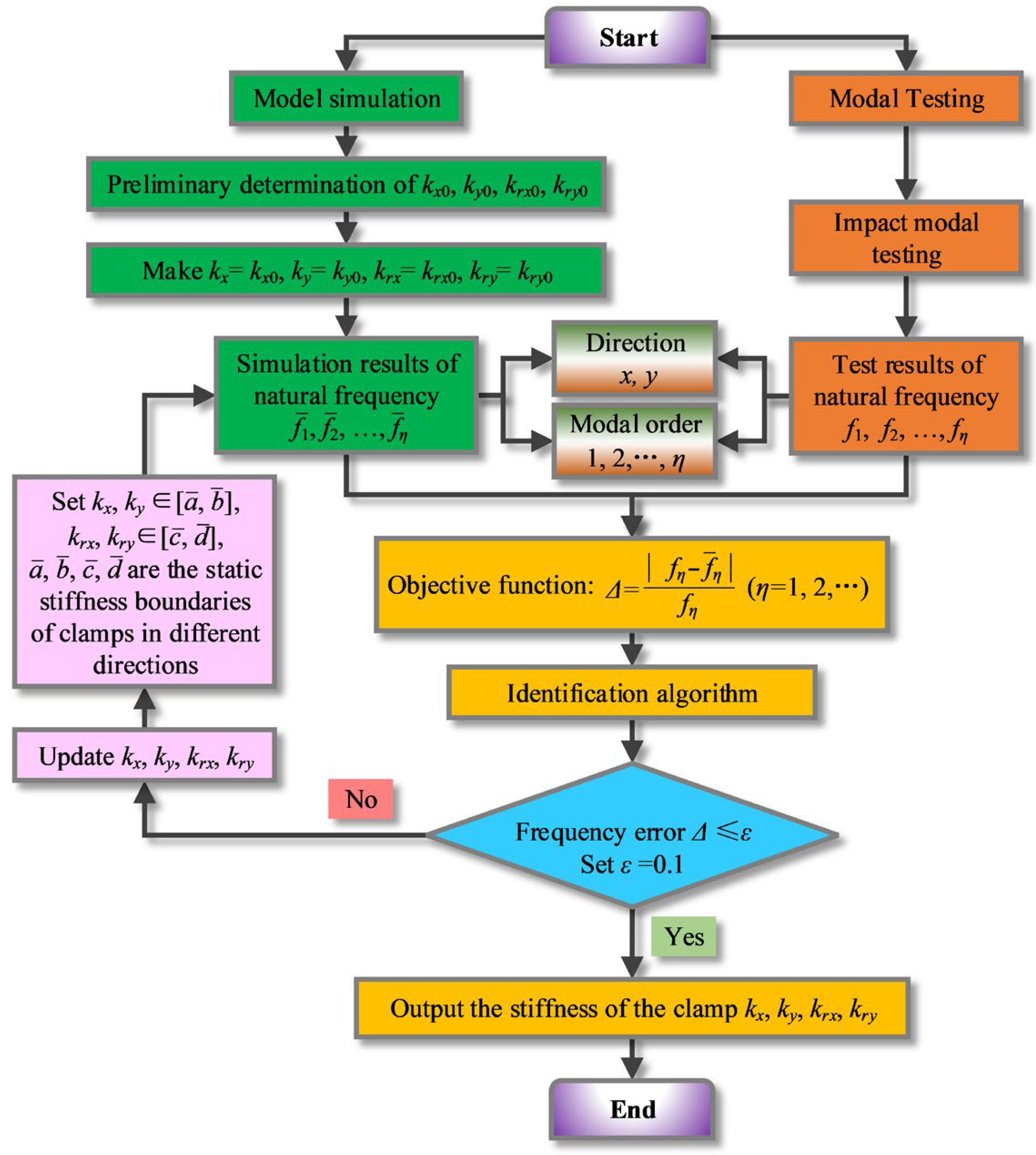
where f η , f ¯ η respectively represent the natural frequencies of the η -th order obtained from modal testing and simulation. Here, the algorithm objective function is constructed based on the deviation between the natural frequencies obtained from simulation and testing. The constraint conditions are set as the variation ranges of the clamp stiffness k x , k y , k r x , k r y , where the boundary of variation a ¯ x , b ¯ x , a ¯ y , b ¯ y , c ¯ r x , d ¯ r x , c ¯ r y , d ¯ r y is determined by static experiments. The identification procedure of clamp stiffness is shown in Figure 8.

3.3. The Damping Identification Procedure of the Clamp

The FRF of the pipeline system is directly affected by the damping of the clamps. Herein, the clamp damping is identified based on FRFs of each order obtained by modal testing and simulation. The identification algorithm for clamp damping is as follows:
min H 1 H ¯ 1 H 1 , H 2 H ¯ 2 H 2 , , H η H ¯ η H η
t ¯ x c x q ¯ x t ¯ y c y q ¯ y 0 ζ κ , ζ τ 1
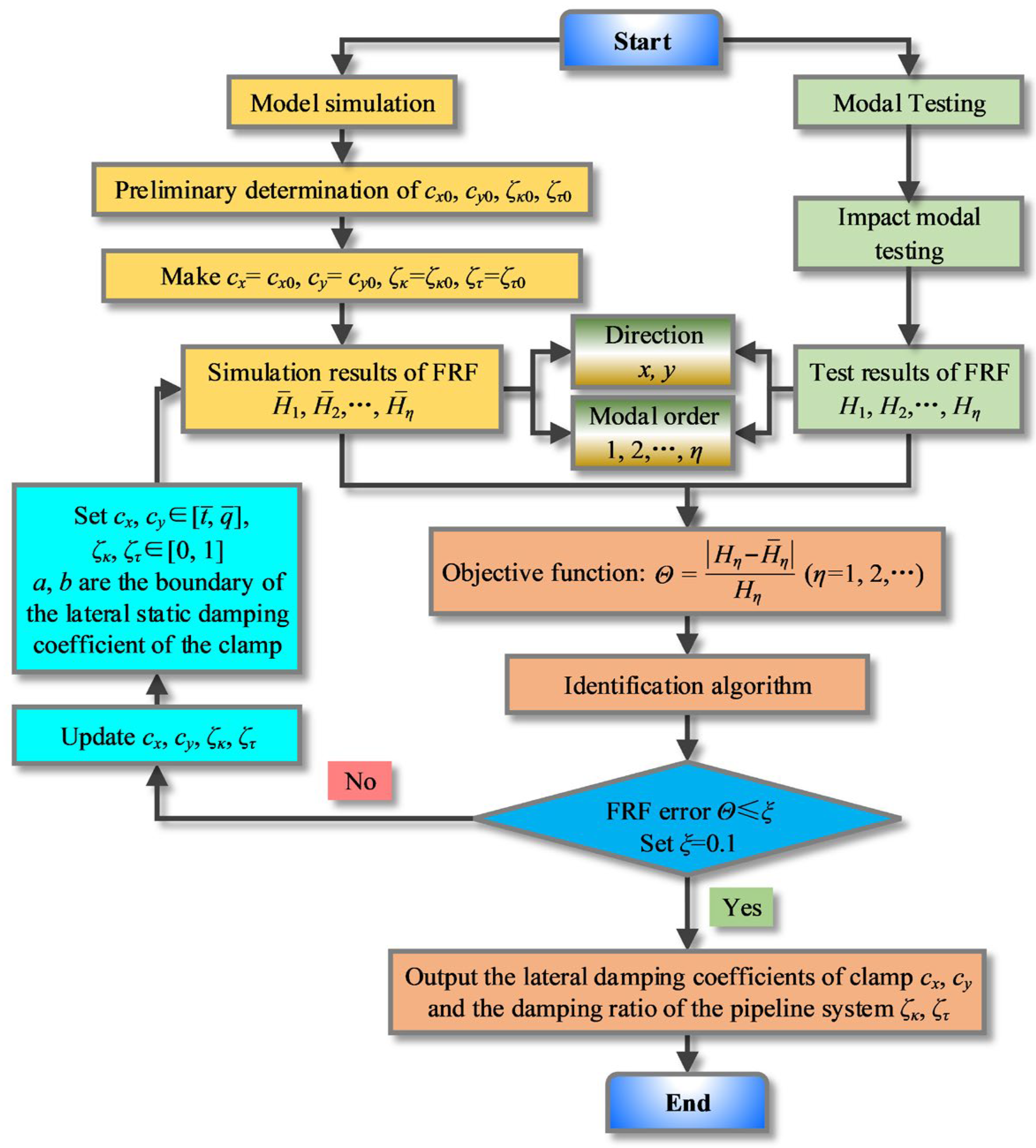
where the objective function of the algorithm is constructed based on the deviation of the peak values of the FRFs obtained from testing and simulation. H η , H ¯ η represent the peak values of the FRFs of η -th order obtained from testing and simulation, respectively. The constraint conditions are set to the variation ranges of the clamp damping coefficient c x , c y and the structural damping ratios ζ κ , ζ τ . The boundaries of variation t ¯ x , q ¯ x , t ¯ y , q ¯ y are also determined by static experiments. The identification process of clamp damping is shown in Figure 9.

4. Experimental Verification

4.1. Experimental System and Testing Results

The experimental system is shown in Figure 10, and modal testing is conducted using the impacting method. An impacting hammer is used to shock the pipe, and a single-axis PCB accelerometer is used for vibration pickup. The acceleration responses in the x and y directions are tested separately. Vibration signals are processed by the LMS data acquisition instrument and transmitted to the LMS testing workstation. The modal data (natural frequencies and FRFs) of the system are obtained through analysis using LMS testing software (version: 2021). The testing equipment used is listed in Table 2.
The uncertainties in this experiment mainly come from three categories: equipment precision errors (systematic errors of the impact hammer’s force sensor, accelerometer, and data acquisition instrument), test environment interference (vibrations in the laboratory environment, electromagnetic interference), and operational errors (repeatability of the impact hammer’s striking position, consistency of accelerometer pasting). To ensure the repeatability of the test results, this experiment conducted multiple independent repeated tests on the same DMRC-double straight pipe structure.
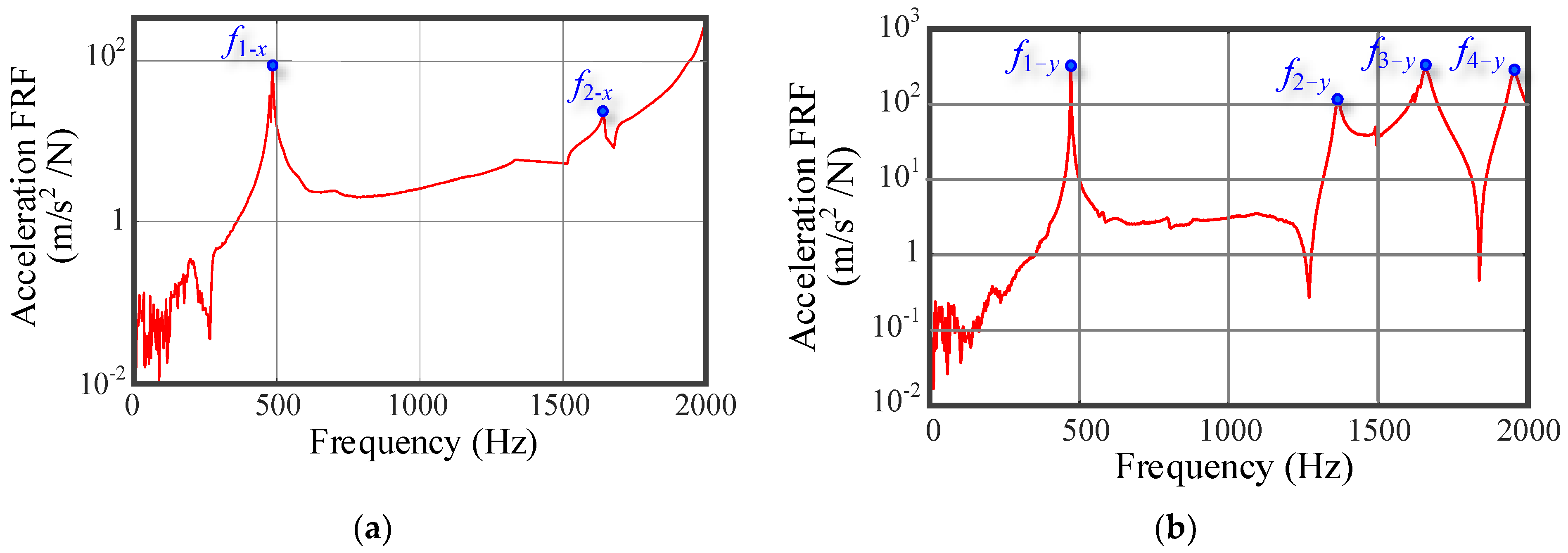
The FRFs in the x and y directions obtained from testing are shown in Figure 11, and the natural frequencies and peak values of the FRFs are listed in Table 3.

4.2. The Process and Results of Identifying Mechanical Parameters of Clamp

Based on the modal test data in the x and y directions, the stiffness and damping of the clamp are identified. Prior to this, the boundary parameters of clamp stiffness and damping are obtained through static testing. The variation ranges of the stiffness and damping identification parameters are shown in Equations (30) and (31). Furthermore, a dynamic model of the DMRC-double straight pipe system will be established based on the MATLAB (version: R2021b) platform, and the stiffness and damping of the clamp will be identified using the Pareto multi-objective genetic algorithm.
3.2 × 10 6 k x 3.9 × 10 6 7 × 10 5 k y 1 × 10 6 103 k r x 115 44 k r y 61
0 ζ κ 1 0 ζ τ 1 18 c x 68 2 c y 68

4.2.1. Stiffness Identification

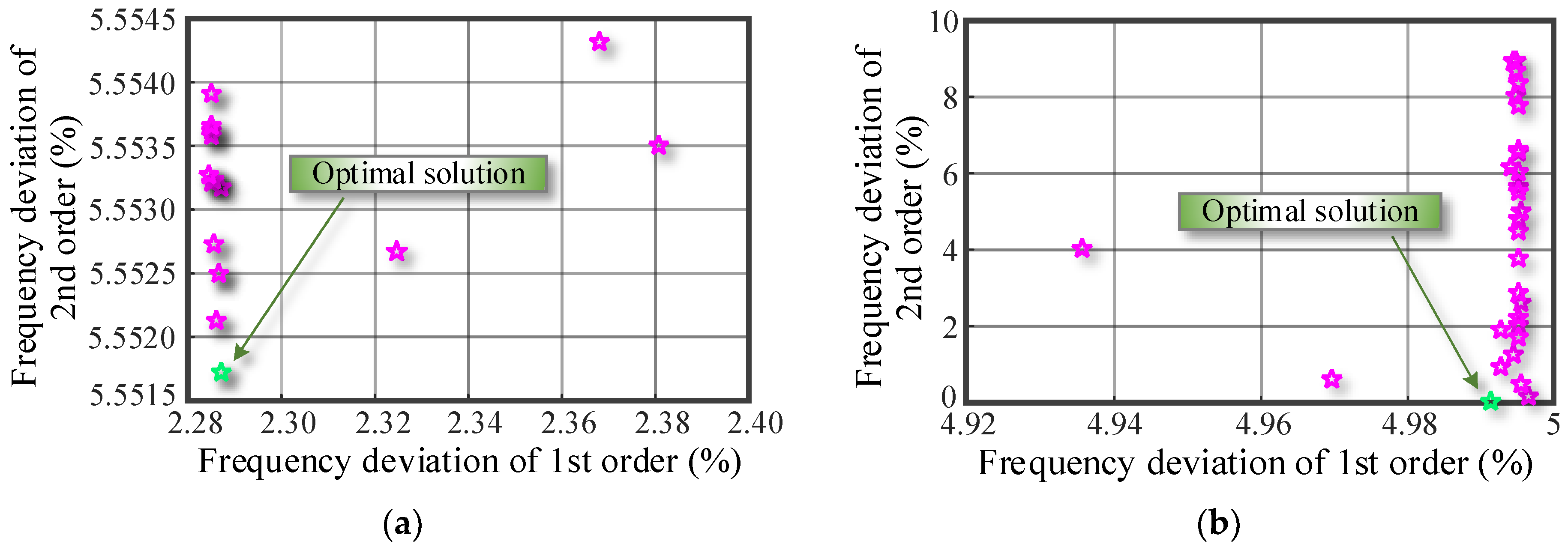
For the natural frequencies in the x and y directions, the deviations between the testing values and the simulation values of 1st and 2nd orders are used as the objective functions, and the clamp stiffnesses of the corresponding order are identified. We set the population size to 30 and iterated 100 times. The optimization result is shown in Figure 12, and the point closest to the origin is selected as the optimal solution (due to space limitations in the paper, only one identification process in the x and y directions is listed). The stiffness identification results are listed in Table 4.
The stiffness identification results of the clamp are imported into the FEM of the DMRC-pipeline system for modal analysis. The simulated natural frequencies are compared with the testing natural frequencies, and the comparison results are shown in Figure 13. The maximum, minimum, and average values of the absolute deviation between the natural frequency of the testing and simulation are 5.55%, 0.0053%, and 3.21%, respectively.

4.2.2. Damping Identification

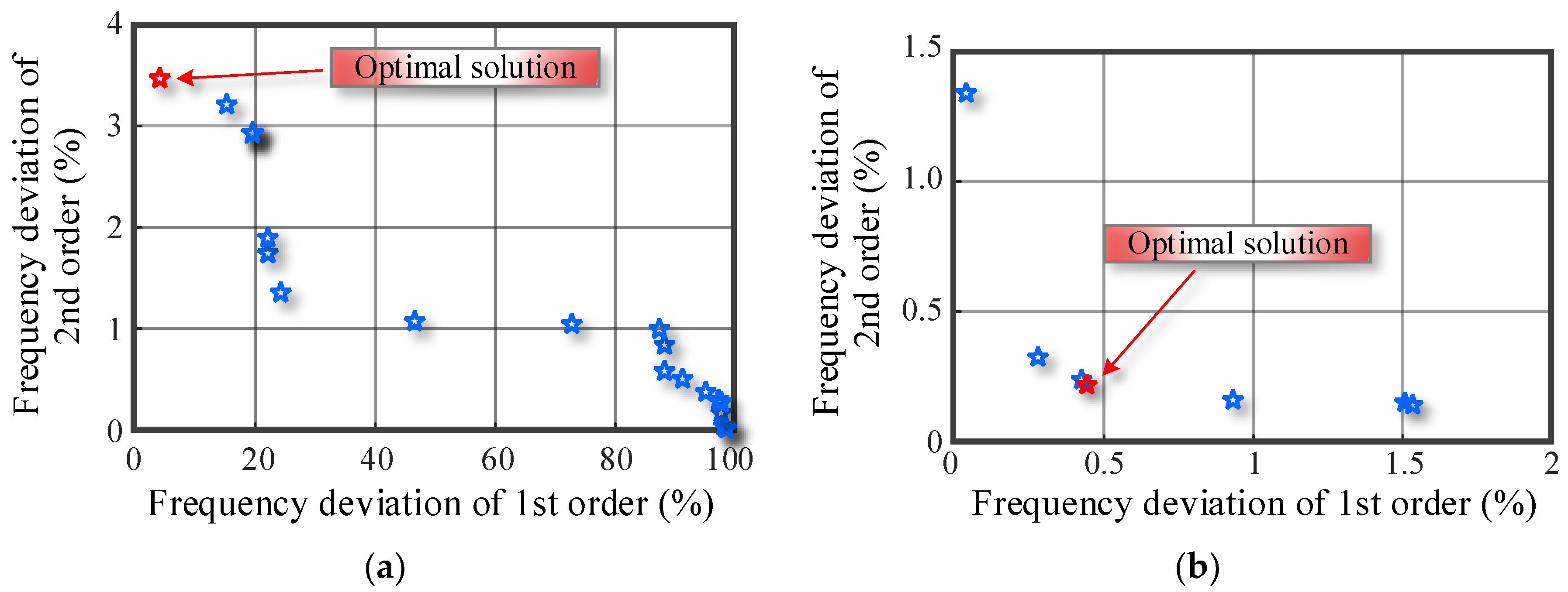
Similarly, based on the first two orders testing FRFs in the x and y directions, the damping coefficient of the clamp and the structure damping ratio of the pipeline system are identified. We set the population size to 30 and iterated 100 times. The identification process is shown in Figure 14, and the damping identification results are listed in Table 5.
Furthermore, the damping identification results of the clamp and pipeline system are input into the FEM of the DMRC-pipeline system for frequency response analysis. The FRF peak values of simulation are compared with that of testing, and the comparison results are shown in Figure 15. The maximum, minimum, and average values of the absolute deviation between the peak values of the testing and simulation are 3.86%, 0.21%, and 1.995%, respectively.
The above comparative analysis results indicate the correctness of the identification results and also verify the effectiveness of the identification method proposed in this paper.

5. Discussion on Method Limitations

The constitutive model equates the DMRC to a “lumped mass—spring-damper set” (Section 2.1). Although it can reflect the differences in bidirectional stiffness and damping, it does not take into account the nonlinear characteristics of DMRC materials (e.g., the law of how the hysteretic characteristics of metal rubber materials change with preload). When the fluctuation range of bolt preload is large, material nonlinearity will lead to the drift of stiffness and damping parameters. However, the current model is only based on the parameter identification results under fixed preload, so its adaptability to scenarios with dynamic preload changes is insufficient.
In addition, this study determines the identification boundaries of stiffness and damping through static experiments, and these boundary conditions are only applicable to the SK8-8-type DMRC and specific pipeline specifications. When the DMRC model or pipeline size changes, the boundary conditions determined by static experiments may become invalid, and it is necessary to conduct static tests again to adjust the parameter range. Otherwise, the identification results may deviate from the actual values.

6. Conclusions

This article aims to identify the dynamic parameters of double clamps and proposes a pipeline structure, identification model, algorithm, and process for identifying clamp parameters. Furthermore, the effectiveness of the identification method is verified through experiments, and the following conclusions are obtained.
  • A DMRC-pipeline system is established for the identification of dynamic parameters of DMRCs, which can effectively reflect the differences in dynamic parameters of DMRC in different directions;
  • A dynamic model of the DMRC-pipeline system is established based on the finite element method, and the stiffness and damping effects of the clamps in different directions are effectively simulated through two spring-damping modules. Based on a Pareto multi-objective genetic algorithm, an algorithm and process for identifying dynamic parameters of the DMRC using modal data (natural frequency and FRF) of the DMRC-pipeline system are proposed;
  • The dynamic parameter identification process of the DMRC is carried out through experimental research, and the identification results are incorporated into the FEM of the pipeline system for simulation analysis. Furthermore, a comparative analysis is conducted on the system’s natural characteristic parameters (natural frequency and peak frequency response function) of the testing and simulation. The maximum and average deviations of the natural frequency are 5.55% and 3.21%, respectively, while the maximum and average deviations of the peak of FRF are 3.86% and 1.995%, respectively. The comparative analysis results show that the identification results of the clamp parameters have good accuracy and also verify the effectiveness of the identification method proposed in this paper.

Author Contributions

K.X.: funding acquisition, writing—original draft, methodology, visualization, validation, data curation. R.W.: writing—original draft, B.W.: resources, supervision. All authors have read and agreed to the published version of the manuscript.

Funding

This work was supported by the National Natural Science Foundation of China (52375085), the major national science and technology projects (J2019-I-0008-0008), and the Guangdong Basic and Applied Basic Research Foundation (2024A1515010675).

Institutional Review Board Statement

Not applicable.

Informed Consent Statement

Not applicable.

Data Availability Statement

The original contributions presented in this study are included in the article. Further inquiries can be directed to the corresponding author.

Conflicts of Interest

The authors declare no potential conflicts of interest with respect to the research, authorship/contribution, and publication of this original paper.

References

  1. Ji, W.H.; Sun, W.; Wang, D.H. A hybrid finite element and extended transfer matrix method for breathing cracks. Mech. Syst. Sig. Process. 2024, 212, 111276. [Google Scholar] [CrossRef]
  2. Yang, T.G.; Li, G.C.; Yuan, S.Y. The LST-SATM-net: A new deep feature learning framework for aero-engine hydraulic pipeline systems intelligent faults diagnosis. Appl. Acoust. 2023, 210, 109436. [Google Scholar] [CrossRef]
  3. Zhang, X.T.; Liu, W.; Zhang, Y.M. Experimental Investigation and Optimization Design of Multi-Support Pipeline System. Chin. J. Mech. Eng. 2021, 34, 10. [Google Scholar] [CrossRef]
  4. Liu, Q.; Tang, Z.; Liu, H.J. Integrated Optimization of Pipe Routing and Clamp Layout for Aeroengine Using Improved MOALO. Int. J. Aerosp. Eng. 2021, 2021, 6681322. [Google Scholar] [CrossRef]
  5. Li, X.; Li, W.H.; Shi, J. Pipelines vibration analysis and control based on clamps’ locations optimization of multi-pump system. Chin. J. Aeronaut. 2022, 35, 352–366. [Google Scholar] [CrossRef]
  6. Sun, A.H.; Yu, R.Y.; Wang, X. Dynamic analysis of liquid-filled clamp-pipe systems based on the spectral element method. Arch. Appl. Mech. 2025, 95, 24. [Google Scholar] [CrossRef]
  7. Yang, Y.B.; Sui, G.H.; Zhang, Y.H. Response spectrum method for fatigue damage assessment of aero-hydraulic pipeline systems. Comput. Struct. 2023, 287, 107119. [Google Scholar] [CrossRef]
  8. Liu, J.Z.; Zhao, Y.L.; Zhu, Q.G. Nonlinear characteristic of clamp loosing in aero-engine pipeline system. IEEE Access 2021, 9, 64076–64084. [Google Scholar]
  9. Chen, W.J.; Cao, Y.M.; Guo, X.M. Nonlinear vibration analysis of pipeline considering the effects of soft nonlinear clamp. Appl. Math. Mech. 2022, 43, 1555–1568. [Google Scholar] [CrossRef]
  10. Jin, J.; Zhu, Z.B.; Cao, Y.L. Dynamic property evaluation of pipeline clamp based on analyzing the propagation characteristics of flexural wave in pipeline. NDT E Int. 2024, 145, 103097. [Google Scholar] [CrossRef]
  11. Zhang, Y.; Sun, W.; Ma, H.W. Semi-analytical modeling and vibration analysis for U-shaped, Z-shaped and regular spatial pipelines supported by multiple clamps. Eur. J. Mech. A-Solids 2023, 97, 104797. [Google Scholar] [CrossRef]
  12. Cao, Y.M.; Guo, X.M. Semi-analytical dynamic modeling and fluid-structure interaction analysis of L-shaped pipeline. Thin-Walled Struct. 2024, 196, 111485. [Google Scholar]
  13. Chen, W.J.; Guo, Z.W.; Chen, S. Semi-analytic modeling and experimental verification of arbitrary aero-engine complex spatial pipeline. Appl. Math. Model. 2024, 131, 505–534. [Google Scholar] [CrossRef]
  14. Ma, H.W.; Sun, W.; Ji, W.H. Nonlinear vibration analysis of Z-shaped pipes with CLD considering amplitude-dependent characteristics of clamps. Int. J. Mech. Sci. 2024, 262, 108739. [Google Scholar] [CrossRef]
  15. Guo, X.M.; Gu, J.F.; Li, H. Dynamic modeling and experimental verification of an L-shaped pipeline in aero-engine subjected to base harmonic and random excitations. Appl. Math. Model. 2024, 126, 249–256. [Google Scholar] [CrossRef]
  16. Guo, X.M.; Cao, Y.M.; Ma, H. Vibration analysis for a parallel fluid-filled pipelines-casing model considering casing flexibility. Int. J. Mech. Sci. 2022, 231, 107606. [Google Scholar] [CrossRef]
  17. Cao, Y.M.; Chai, Q.D.; Guo, X.M. Comparative study on two finite element models for multi-clamp pipeline system. J. Mech. Sci. Technol. 2022, 36, 1157–1169. [Google Scholar] [CrossRef]
  18. Cao, Y.M.; Guo, X.M.; Ma, H. Dynamic modelling and natural characteristics analysis of fluid conveying pipeline with connecting hose. Mech. Syst. Sig. Process. 2023, 193, 110244. [Google Scholar] [CrossRef]
  19. Guo, X.M.; Ma, H.; Zhang, X.F. Uncertain frequency responses of clamp-pipeline systems using an interval-based method. IEEE Access 2020, 8, 29370–29384. [Google Scholar] [CrossRef]
  20. Liu, Z.H.; Shan, Z.C.; Zhang, X.F. Uncertain frequency response analysis of clamp-pipe systems via the coordinate transformed polynomial chaos expansion. Int. J. Press. Vessel. Pip. 2022, 19, 104720. [Google Scholar] [CrossRef]
  21. Ma, H.W.; Sun, W.; Ji, W.H. Dynamic modeling and vibration analysis of planar pipeline with partial constrained layer damping treatment: Theoretical and experimental studies. Compos. Struct. 2023, 323, 117476. [Google Scholar] [CrossRef]
  22. Ma, H.W.; Sun, W.; Wang, D. Finite element modeling of straight pipeline with partially attached viscoelastic damping patch based on variable thickness laminated element. Compos. Struct. 2022, 314, 116944. [Google Scholar] [CrossRef]
  23. Liu, Y.; Wei, J.T.; Du, H. An analysis of the vibration characteristics of an aviation hydraulic pipeline with a clamp. Aerospace 2023, 10, 900. [Google Scholar] [CrossRef]
  24. Ji, W.H.; Sun, W.; Zhang, Y. Parametric model order reduction and vibration analysis of pipeline system based on adaptive dynamic substructure method. Structures 2023, 50, 689–706. [Google Scholar] [CrossRef]
  25. Zhang, X.T.; Liu, W. The effect of pipeline layout parameters on mode and dynamic stress of “airframe-clamps-pipeline” structure. Multidiscip. Model. Mater. Struct. 2020, 16, 373–389. [Google Scholar] [CrossRef]
  26. Zhang, L.; Zhang, T.; Ouyang, H.J. Natural frequency assignment of a pipeline through structural modification in layout optimization of elastic supports. J. Sound Vib. 2023, 561, 117702. [Google Scholar] [CrossRef]
  27. Zhang, Y.; Sun, W.; Ji, W.H. Hoop layouts optimization for vibration reduction of L-shaped pipeline based on substructure-analytical model and genetic algorithm. J. Braz. Soc. Mech. Sci. 2023, 45, 243. [Google Scholar] [CrossRef]
  28. Chen, H.T.; Zhang, L.; Zhang, T. FRF-based model updating of liquid-filled pipeline system considering tolerance intervals of test errors in the antiresonant frequencies. Eng. Struct. 2024, 307, 117818. [Google Scholar] [CrossRef]
  29. Gao, P.X.; Li, J.W.; Zhai, J.Y. A Novel Optimization Layout Method for Clamps in a Pipeline System. Appl. Sci. 2020, 10, 390. [Google Scholar] [CrossRef]
  30. Liu, F.M.; Sun, W.; Zhang, H. Dynamic modeling and stress reduction optimization of parallel pipelines based on pipe-solid element coupling. Int. J. Press. Vessel. Pip. 2024, 207, 105107. [Google Scholar] [CrossRef]
  31. Chen, W.J.; Cao, Y.M.; Chen, S. Semi-analytical dynamic modeling of parallel pipeline considering soft nonlinearity of clamp: A simulation and experimental study. Mech. Syst. Sig. Process. 2023, 201, 110648. [Google Scholar] [CrossRef]
  32. Guo, X.M.; Xiao, C.L.; Ge, H. Dynamic modeling and experimental study of a complex fluid-conveying pipeline system with series and parallel structures. Appl. Math. Model. 2022, 109, 186–208. [Google Scholar] [CrossRef]
  33. Gao, P.X.; Zhang, Y.L.; Liu, X.F. Vibration analysis of aero parallel-pipeline systems based on a novel reduced order modeling method. J. Mech. Sci. Technol. 2020, 34, 3137–3146. [Google Scholar] [CrossRef]
  34. Chai, Q.D.; Zeng, J.; Ma, H. A dynamic modeling approach for nonlinear vibration analysis of the L-type pipeline system with clamps. Chin. J. Aeronaut. 2020, 33, 3253–3265. [Google Scholar] [CrossRef]
  35. Lin, J.Z.; Niu, Z.H.; Zhang, X.F. Clamp nonlinear modeling and hysteresis model parameter identification. IEEE Access 2021, 9, 47757–147767. [Google Scholar] [CrossRef]
  36. Cao, Y.M.; Chen, W.J.; Ma, H. Dynamic modeling and experimental verification of clamp-pipeline system with soft nonlinearity. Nonlinear Dyn. 2023, 111, 17725–17748. [Google Scholar] [CrossRef]
  37. Wang, Z.C.; Gao, P.X.; Zhou, Z.D. A numerically stable flexural dynamics model of complex multi-span fluid-conveying pipes with flexible components and its application to clamp stiffness identification. Thin-Walled Struct. 2024, 195, 111488. [Google Scholar] [CrossRef]
  38. Zhu, H.Y.; Liu, W.; Li, W.Z. Dynamic identification method for stiffness of duplex suspension clamp based on system modes. Structures 2023, 57, 105284. [Google Scholar] [CrossRef]
Figure 1. DMRCs in pipeline systems and the structure of DMRCs.
Applsci 15 11239 g001
Figure 2. Support effect of DMRC.
Applsci 15 11239 g002
Figure 3. DMRC-double straight pipe system.
Applsci 15 11239 g003
Figure 4. Discretization model of DMRC.
Applsci 15 11239 g004
Figure 5. Timoshenko beam element for pipe.
Applsci 15 11239 g005
Figure 6. Experimental structure and its finite element model: (a) experimental structure; (b) FEM of experimental structure.
Applsci 15 11239 g006
Figure 7. The method for assembling the stiffness matrix and damping matrix of the DMRC-pipeline system.
Applsci 15 11239 g007
Figure 8. Stiffness identification procedure of DMRC.
Applsci 15 11239 g008
Figure 9. Damping identification procedure of DMRC.
Applsci 15 11239 g009
Figure 10. Modal test of DMRC-pipeline system.
Applsci 15 11239 g010
Figure 11. FRFs of the DMRC-pipeline system: (a) x direction; (b) y direction.
Applsci 15 11239 g011
Figure 12. Identification process of clamp stiffness; (a) x direction; (b) y direction.
Applsci 15 11239 g012
Figure 13. Natural frequencies and frequency deviations of testing and simulation.
Applsci 15 11239 g013
Figure 14. Identification process of clamp damping; (a) x direction; (b) y direction.
Applsci 15 11239 g014
Figure 15. FRF peak value and peak value deviations of testing and simulation.
Applsci 15 11239 g015
Table 1. The material and structural parameters of the pipe.
Elastic Modulus
(GPa)
Density
(kg/m3)
Poisson’s
Ratio
Length
(mm)
Outer Diameter
(mm)
Inner Diameter
(mm)
19078500.340386.4
Table 2. Testing equipment.
Serial NumberInstrumentManufacturer
1LMS SCADAS mobile front endSiemens/Germany
2Acceleration lightweight sensorBK/Denmark
3LMS Test. lab mobile workstationSiemens/Germany
4PCB 8206-001 54627 exciting hammerPCB/USA
Table 3. The natural frequencies and peak values of the FRFs.
Order–Directionf1xf2xf1yf2yf3yf4y
Natural frequency (Hz)484.3751640.625471.8751365.6251659.3751953.125
Peak value of FRF (m/s2/N)76.843521.0613304.4037108.1294290.1738259.7483
Table 4. Identification results of clamp stiffness.
Order and Direction of Testing Data1st and 2nd Orders in x Direction1st and 2nd Orders in y Direction
Stiffness in x   direction   k x (N/m)3.2 × 1063.683 × 106
Stiffness in y   direction   k y (N/m)7.0 × 1058.929 × 105
x - axis   rotational   stiffness   k r x (N·m/rad)103.84104.741
y - axis   rotational   stiffness   k r y (N·m/rad)44.0056.814
Table 5. Identification results of damping coefficient of clamp and structure damping ratio of the pipeline system.
Order and Direction of Testing Data1st and 2nd Orders in x Direction1st and 2nd Orders in y Direction
Structure   damping   ratio   ζ κ 2.97 × 10−36.33 × 10−4
Structure   damping   ratio   ζ τ 7.63 × 10−24.72 × 10−3
Damping coefficient of clamp c (N·s/m)38.5337.57
Disclaimer/Publisher’s Note: The statements, opinions and data contained in all publications are solely those of the individual author(s) and contributor(s) and not of MDPI and/or the editor(s). MDPI and/or the editor(s) disclaim responsibility for any injury to people or property resulting from any ideas, methods, instructions or products referred to in the content.