Article

Sliding Mode Observer-Based Sensorless Control Strategy for PMSM Drives in Air Compressor Applications

School of Electrical Engineering, Southeast University, Nanjing 210096, China
*
Author to whom correspondence should be addressed.
Appl. Sci. 2025, 15(20), 11206; https://doi.org/10.3390/app152011206
Submission received: 19 September 2025 / Revised: 10 October 2025 / Accepted: 15 October 2025 / Published: 19 October 2025

Abstract

This paper presents a sensorless control strategy for permanent magnet synchronous motor (PMSM) drives in industrial and automotive air compressor applications. The strategy utilizes an adaptive-gain sliding mode observer integrated with a refined back-EMF model to suppress chattering and improve convergence. The proposed approach achieves precise rotor position and speed estimation across a wide operational range without mechanical sensors. It directly addresses the critical needs of reliability, compactness, and resilience in automotive environments. Unlike conventional observers, its originality lies in the enhanced gain structure, enabling accurate and robust sensorless control validated through both simulation and hardware tests. Comprehensive simulation results demonstrate effective performance from 2000 to 8500 rpm, with steady-state speed tracking errors maintained below 0.4% at 2000 rpm and 0.035% at 8500 rpm under rated load. The control methodology exhibits excellent disturbance rejection capabilities, maintaining speed regulation within ±5 rpm under an 80% load disturbance at 8500 rpm while limiting q-axis current ripple to 2.5% of rated values. Experimental validation on a 2.2 kW PMSM-driven compressor test platform confirms stable operation at 4000 rpm with speed fluctuations constrained to 20 rpm (0.5% error) and precise current regulation, maintaining the d-axis current within ±0.07 A. The system demonstrates rapid dynamic response, achieving acceleration from 1320 rpm to 2365 rpm within one second during testing. The results confirm the method’s practical viability for enhancing reliability and reducing maintenance in industrial and automotive compressors systems.

1. Introduction

Permanent magnet synchronous motors (PMSMs) are widely recognized for their superior power density, high efficiency, and compact design, making them integral to air compressor applications in industrial systems [1,2,3]. Air compressors, extensively utilized across manufacturing, automotive, and energy sectors, demand precise and reliable motor control to optimize energy consumption, ensure operational stability, and reduce downtime [4,5]. Effective control of PMSMs significantly impacts the compressor’s ability to maintain consistent pressure and flow rates under varying load conditions [6]. The operating environment for these compressors is highly dynamic, involving frequent start-stop cycles and operation across broad speed ranges. Consequently, implementing robust control strategies is essential to ensure sustained performance and long-term system reliability [7,8]. PMSMs are well-suited for these conditions due to their capability to deliver high torque and efficiency, contingent upon accurate rotor position and speed information for precise control [9,10,11].
Conventionally, PMSM control systems rely on physical sensors such as optical encoders or resolvers to measure rotor position and speed [12,13]. While these sensors provide accurate feedback, their integration introduces notable challenges, especially in the industrial and automotive environments typical of air compressors [14]. The inclusion of sensors increases overall system cost, factoring in not only the sensor hardware but also additional cabling, connectors, and signal processing units. This increases both system complexity and maintenance requirements [15]. Moreover, physical sensors are vulnerable to environmental stressors such as elevated temperature, mechanical vibrations, dust, and moisture [16,17,18]. These conditions can degrade sensor performance, risking erroneous readings, reduced reliability, and potential system failures [19,20]. For example, optical encoders may suffer from misalignment or contamination. These issues can result in inaccurate position measurements [21]. These limitations motivate the exploration of alternative sensorless control approaches [22].
Sensorless control strategies estimate rotor position and speed based solely on electrical signals, eliminating the reliance on mechanical sensors [23,24]. These methods generally fall into two categories: high-frequency injection (HFI) techniques and model-based observers [25]. HFI techniques are effective at zero and low speeds. However, they introduce high-frequency noise that can degrade system efficiency, and their dependence on rotor saliency restricts their use to specific PMSM designs [26]. Model-based approaches, especially those leveraging extended electromotive force (EMF) models, are suitable for medium and high-speed applications and are non-invasive [27]. However, the accuracy of EMF-based methods frequently diminishes at low speeds because of low signal-to-noise ratios. This limitation presents a significant challenge for air compressors, which require stable performance across wide speed ranges [28]. Alternative techniques, such as the active flux (AF) model, necessitate integrators, introducing problems related to DC offsets and initial condition sensitivity [29].
This paper introduces a sensorless control strategy for PMSM drives in industrial air compressors, utilizing a sliding mode observer-based on the back-EMF model. SMOs are known for their robustness and relatively straightforward implementation compared to linear observers, employing sliding-mode variable structure control that imparts insensitivity to parameter variations and external disturbances [30]. Despite these advantages, conventional SMOs frequently suffer from the chattering phenomenon and limited convergence speed [31]. The proposed method addresses these limitations through a refined gain structure and a carefully designed switching function. This approach effectively reduces chattering effects while improving convergence performance across a wide speed range. Building on established back-EMF-based SMO frameworks, the technique enhances control algorithms to optimize estimation accuracy and robustness. Simulation and experimental validations demonstrate the efficacy of the approach in achieving stable and precise sensorless operation. The main contributions of this work are: (1) an adaptive-gain sliding mode observer structure for PMSM drives that reduces chattering and enhances estimation accuracy; (2) integration with back-EMF estimation tailored for compressor applications; and (3) combined simulation and experimental validation proving practical viability with low computational cost. These contributions highlight the originality and industrial relevance of the proposed method.
Specifically, the proposed sliding mode observer strategy is designed to operate effectively in high-speed regimes characteristic of industrial air compressor systems. Experimental results validate that the method achieves stable and precise speed regulation under dynamic loading conditions. The proposed observer is designed to enhance stability and reduce estimation errors, specifically under the transient load changes typical of compressor applications, operating effectively in the medium-to-high speed regime.

2. Mathematical Model and Vector Control of PMSM

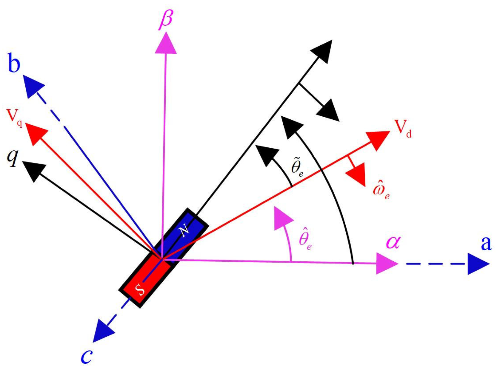
Figure 1 illustrates the conventional sliding mode observer implementation within the PMSM sensorless drive architecture. This configuration eliminates the mechanical position sensor by processing measured stator voltages and currents to estimate rotor position ( θ ^ e ) and speed ( ω ^ e ). These estimated values serve dual purposes: enabling speed control loop regulation and facilitating coordinate transformations in the field-oriented control (FOC) scheme. The SMO design methodology, implemented in either the stationary α β -frame or estimated rotating frame as depicted in Figure 2, is critically examined in this section. Comparative analysis of both reference v d v q frame implementations follows to evaluate their respective performance characteristics.

2.1. Mathematical Model of PMSM

The dynamic model of a permanent magnet synchronous motor (PMSM) is established in the rotor-aligned synchronous reference frame (d-q axes) to enable precise control analysis. This transformation aligns the coordinate system with the rotor flux position, decoupling torque, and flux production mechanisms. The stator voltage equations are defined as:
u d = R s i d + L d d i d d t ω e L q i q
u q = R s i q + L q d i q d t + ω e L d i d + ω e λ f
where u d and u q denote d q -axis stator voltages; i d and i q represent flux-producing and torque-producing currents; R s is stator winding resistance; The flux linkages incorporate the magnetic saliency and permanent magnet contribution:
λ d = L d i d + λ f
λ q = L q i q
Here, L d and L q signify d-q axis inductances, while λ f represents the constant flux linkage due to rotor-mounted permanent magnets.
Position sensorless control precludes direct use of the standard d q -axis model due to the unavailability of rotor position measurements. Instead, control implementations employ a mathematical formulation in an estimated v d , v q reference frame. This estimated frame lags the actual d q frame by an angular displacement θ ˜ e (Figure 2), derived through the transformation of Equations (1) and (2) into the v d , v q axes:
u d v = R s i d v + d λ d v d t ω ^ e λ q v u q v = R s i q v + d λ q v d t ω ^ e λ d v
with flux linkages defined as
λ d v = L d cos 2 θ ˜ e + L q sin 2 θ ˜ e i d v + L q L d sin θ ˜ e cos θ ˜ e     i q v + λ m sin θ ˜ e λ q v = L q L d sin θ ˜ e cos θ ˜ e     i d v + L d sin 2 θ ˜ e + L q cos 2 θ ˜ e i q v + λ m cos θ ˜ e
The voltage equations in the v d , v q frame retain the resistive drop R s i and flux derivative d t terms from the original d q model but incorporate rotational electromotive forces ± ω ^ e λ due to frame misalignment. The flux linkages λ d v , λ q v introduce cross-coupling through θ ˜ e -dependent inductance transformations and permanent magnet flux λ m reorientation. Crucially, the inductance terms L d cos 2 θ ˜ e + L q sin 2 θ ˜ e and L d sin 2 θ ˜ e + L q cos 2 θ ˜ e manifest position-dependent saliency effects, while L q L d sin θ ˜ e cos θ ˜ e coefficients represent mutual coupling between v d , v q axes induced by the angular error.
The Electromagnetic Torque T e (Nm) is derived from
T e = 3 P 4 λ d i q λ q i d
Substituting (3) and (4) into (7) yields
T e = 3 P 4 λ f i q + L d L q i d i q
where P is the number of poles.
Under steady-state operation with constant load angle δ (the angle between the stator current vector and q-axis), Equation (8) transforms to:
T e = 3 P 4 λ f i s sin δ + 1 2 L d L q i s 2 sin 2 δ
where i s = i d 2 + i q 2 is the stator current magnitude. This formulation highlights the torque dependence on saliency L d L q and load angle, critical for sensorless control in variable-load applications like air compressors.

2.2. Vector Control of PMSM

Field-oriented control (FOC) facilitates precise torque and speed regulation in permanent magnet synchronous motors (PMSMs). This is achieved by decoupling the flux and torque-producing current components within the rotor-aligned d-q reference frame. This technique transforms three-phase stator currents into orthogonal direct-axis i d and quadrature-axis i q currents, emulating separate excitation in DC motors. For air compressor applications—where efficient startup and load-tracking are critical—a cascaded control structure is implemented:
A PI regulator processes the speed error ω m * ω m to generate the torque-reference current i q * :
i q * = K p , ω ω m * ω m + K i , ω ω m * ω m   d t
where ω m * and ω m are reference and measured mechanical speeds, and K p , ω , K i , ω are PI gains. i d is set i d * = 0 for constant torque angle control δ = 90 , maximizing torque per ampere below base speed. PI controllers regulate i d and i q to track references:
u d = K p , d i d * i d + K i , d i d * i d   d t ω e L q i q
u q = K p , q i q * i q + K i , q i q * i q   d t + ω e L d i d + λ f
Cross-coupling terms ω e L q i q ω e λ f compensate for back-EMF effects.
At δ = 90 , the electromagnetic torque simplifies to:
T e = 3 P 4 λ f i q = k t i q
where P is the pole count, λ f is the permanent magnet flux linkage, and k t = 3 P 4 λ f is the torque constant.

3. Sensorless Control Based on SMO

3.1. Sliding Mode Observer Design in Stationary αβ-Frame

For sensorless control of permanent magnet synchronous motors (PMSMs) in air compressor systems, a sliding mode observer is implemented in the stationary α β -reference frame. This nonlinear technique drives current estimation errors to a predefined sliding manifold using discontinuous control action, enabling robust estimation of back-EMF, rotor position, and speed from measurable stator variables. The PMSM dynamics in the α β -frame are expressed as:
d i α d t = R s L s i α + 1 L s v α e α d i β d t = R s L s i β + 1 L s v β e β
where i α , i β are α β -axis currents; v α , v β denote α β -axis voltages; R S is stator resistance; L S represents synchronous inductance; and e α , e β are back-EMF components expressed as:
e α = ω e λ f sin θ e e β = ω e λ f cos θ e
Here, ω e is the electrical rotor speed, λ f is the permanent magnet flux linkage, and θ e is the electrical rotor position. The observer structure mirrors the plant but incorporates a switching term to force current errors to zero:
d i ^ α d t = R s L s i ^ α + 1 L s v α z α d i ^ β d t = R s L s i ^ β + 1 L s v β z β
where i ^ α , i ^ β are estimated currents, and z α , z β represent switching functions:
z α = k sat i ˜ α , z β = k sat i ˜ β
With k as the observer gains, sat a saturation function to suppress chattering, and i ˜ α = i ^ α i α , i ˜ β = i ^ β i β defining current errors. The sliding manifold is:
S = i ˜ α , i ˜ β | i ˜ α = 0 ,   i ˜ β = 0
When S is reached i ˜ α = i ˜ β = 0 , the equivalent control terms z α and z β converge to e α and e β . Low-pass filtering extracts the back-EMF:
e ^ α = ω c S + ω c z α , e ^ β = ω c S + ω c z β
where ω c is the cutoff frequency. Rotor position θ ^ e and speed ω ^ e are then derived:
θ ^ e = arctan e ^ α e ^ β
ω ^ e = 1 φ f e ^ α 2 + e ^ β 2

3.2. Conventional Sliding Mode Observer

Conventional sliding mode observers for sensorless PMSM drives utilize discontinuous signum functions to force current estimation errors to zero. The observer replicates the motor dynamics in the stationary αβ-frame:
d i ^ α d t = R s L s i ^ α + 1 L s v α z α d i ^ β d t = R s L s i ^ β + 1 L s v β z β
where switching terms z α = k . sgn i ˜ α and z β = k . sgn i ˜ β inject high-frequency components.
Here, k denotes the observer gain i ˜ α = i ^ α i α , i ˜ β = i ^ β i β , and the signum function is defined as:
sgn x = 1 x > 0 0 x = 0 1 x < 0
Current error dynamics are derived from (22) and (23):
d i ˜ α d t = R s L s i ˜ α + 1 L s e α z α d i ˜ β d t = R s L s i ˜ β + 1 L s e β z β
At the sliding surface i ˜ α = i ˜ β = 0 , the equivalent control satisfies z α = e α and z β = e β .
Low-pass filtering extracts the back-EMF:
e ^ α = ω c s + ω c z α , e ^ β = ω c s + ω c z β
where ω c is the cutoff frequency. Rotor position is calculated with phase compensation:
θ e = tan 1 e ^ α e ^ β , θ comp = tan 1 ω e ω e
The compensation in the value of the rotor position can be achieved by:
θ actual = θ e + θ comp
Rotor speed can be calculated by:
ω e = d θ actual d t

3.3. Design of Higher-Order Sliding Mode Observers for Sensorless PMSM Control

The full-order sliding mode observer utilizes stator currents and electromotive force (EMF) components as state variables. This configuration maintains estimation accuracy with lower gain requirements. The observer dynamics in the stationary reference frame are governed by:
d d t i ^ α β e ^ α β = A 0 i ^ α β e ^ α β + B 0 v α β G 0 L d sgn i ˜ α β
where i ˜ α β = i ^ α β i α β denotes current estimation error, v α β represents stator voltage, and L d is the d -axis inductance.
The system matrices are defined as:
A 0 = R s L d ω ^ e L Δ L d 1 L d 0 ω ^ e L Δ L d R s L d 0 1 L d 0 0 0 ω ^ e 0 0 ω ^ e 0 ; B 0 = 1 L d 0 0 1 L d 0 0 0 0 ; G 0 = l 1 0 m 1 0 0 l 2 0 m 2
Here, R s is stator resistance ω ^ e denotes the estimated electrical velocity, L Δ = L d L q reflects inductance saliency, and g α 1 ,   g α 2 ,   g β 1 ,   g β 2 are observer gain.
For stability, the gains must satisfy:
g α 1 , g β 1 > max | e ˜ α | , | e ˜ β |
where e ˜ α β represents the back-EMF estimation error.
This configuration reduces the sliding gain magnitude but increases computational load due to fourth-order state representation. Performance is further constrained by the assumption of negligible back-EMF time derivatives. The super-twisting algorithm (STA) implements a continuous control law to eliminate chattering while preserving disturbance rejection capabilities:
u STA = k 1 i ˜ α β 1 / 2 sgn i ˜ α β + ζ d ζ d t = k 2 sgn i ˜ α β
where u STA is the continuous control input ζ denotes an auxiliary state variable, and k 1 , k 2 are adaptive gain coefficients. The discontinuous term in the ζ dynamics integrates into u STA , creating an inherent signal smoothing equivalent to a low-pass filter. This structure fundamentally suppresses high-frequency switching artifacts but introduces sensitivity to gain selection. Optimal performance requires balancing convergence rate k 1 and disturbance rejection k 2 , with inadequate tuning leading to either sluggish response or residual oscillations under rapid torque transitions.

3.4. Adaptive Gain Methodologies for Chattering Suppression

Conventional sliding mode observers require high fixed gains to handle disturbance upper bounds, which amplifies chattering. Advanced adaptive SMO formulations mitigate this via dynamic gain modulation. Certain methods establish extended back-EMF boundaries from machine parameters and operational points; however, these approaches exhibit significant parametric sensitivity. Alternative approaches integrate adaptive control principles to eliminate disturbance-bound dependencies, formalized by:
K α β ( τ ) = λ 0 τ σ α β μ K α β ζ   d ζ
where λ and μ are positive tuning coefficients. This structure increases K α β when σ α β > μ K α β ζ , accelerating convergence to the sliding surface. At σ α β = 0 , the gain stabilizes at a minimal value satisfying reachability conditions, with autonomous readjustment during load/speed transients to maintain sliding-mode stability. Although independent of disturbance bounds, optimal performance requires empirical calibration of λ and μ . Fuzzy logic systems provide supplementary adaptation by scaling SMO gains proportionally to current tracking errors. This method suppresses chattering without compromising stability. However, its reliance on empirically derived, fixed input universes necessitates complex rule bases to achieve precision. This induces a significant computational burden, challenging deployment in industrial PMSM-driven air compressors for Electric Vehicles (EVs).

3.5. Adaptive Gain Mechanism for Enhanced SMO in PMSM Drives

To enhance the sensorless control of permanent magnet synchronous motor (PMSM) drives for air compressor applications in the automotive industry, an adaptive gain strategy is proposed, utilizing the back-EMF estimation framework within a sliding mode observer. The back-EMF estimation error in the αβ reference frame is expressed as:
δ α δ β = L s d d t i α β e s t i α β + D α β i α β e s t i α β
This equation defines the foundation of the EMF estimation error dynamics in the stationary frame. The transition to an adaptive Non-singular Terminal Sliding Mode Observer (NTSMO) is driven by the stringent demands of air compressor applications, where frequent start-stop cycles and rapid load changes are prevalent. Conventional SMOs suffer from chattering and slow convergence, which degrade performance under such dynamic conditions. The proposed NTSMO uniquely ensures finite-time convergence and suppresses chattering through its adaptive gain, providing the precise, robust estimation necessary for stable compressor operation and mechanical longevity. where D α β is defined as:
D α β = R s L s ω s e s t L σ L s ω s e s t L σ L s R s L s
This term encapsulates the dynamic relationship between current errors, stator parameters, and saliency, forming the basis for the adaptive mechanism. In Equation (34), the right-hand side comprises two key terms that model the dynamics of the EMF estimation error. The first term, L s d d t i ^ α β i α β represents the voltage induced by the rate of change in the current estimation error, where L s is the stator inductance and i ^ α β i α β denotes the vector of differences between estimated and measured stator currents in the stationary α β frame. The second term, D α β i ^ α β i α β captures the combined effects of resistive voltage drops, rotational coupling due to the estimated stator angular frequency ω ^ s and rotor saliency, with D α β as the system matrix defined in Equation (35) incorporating stator resistance R s inductance L s and the saliency factor σ reflecting inductance asymmetry (typically σ = L q L d / L s ) . These terms collectively ensure accurate error propagation modeling for robust observer convergence in PMSM air compressor drives.
Conventional sliding mode observer designs ensure that the current error i α β e s t i α β converges to zero on the sliding surface, but nonzero derivatives of this error can degrade back-EMF and rotor position estimation accuracy. To address this, a nonsingular terminal sliding mode observer with an adaptive gain approach is introduced. The proposed observer differs fundamentally from the super-twisting observer (STO) by unifying a nonsingular terminal sliding surface with an adaptive gain law. This structure guarantees finite-time convergence of both the current error and its derivative, overcoming the STO’s fixed-gain trade-off between convergence and chattering. The result is superior transient response and chattering suppression under dynamic compressor loads without conservative gain tuning. The sliding surface is formulated as:
σ α β = i α β e s t i α β + ρ d d t i α β e s t i α β p q
where ρ > 2 and 1 < p q < 2 .
This surface ensures finite-time convergence of both the current error and its derivative to zero, overcoming limitations of conventional sliding surfaces. Where ρ > 2 , and p and q are positive odd integers satisfying 1 < p q < 2 to ensure a real-valued fractional exponent and guarantee nonsingular terminal convergence. For implementation, values of p = 5 and q = 3 are selected. In Equation (36), ρ stabilizes the sliding dynamics while the fractional exponent p/q ensures finite-time convergence of both current errors and their derivatives to zero. The total convergence time t f is given by:
t f = t m + p p q max j = α ,   β ρ 1 q i j e s t i j t m p q p
where t m is the time when σ α β reaches zero.
This equation provides the finite convergence time guarantee, a key advantage of the terminal sliding mode approach. In Equation (37), t f is the total convergence time, t m is the time to reach the sliding surface, and max j = α ,   β selects the maximum current error in the α or β axis. To suppress chattering, a higher-order terminal sliding mode observer with adaptive gain is employed. The sliding mode control law is defined as:
ω α β = ϕ i α β e s t i α β γ sgn i α β e s t i α β ψ 1 , d ψ 1 d t = k 4 sgn σ N T S M O + ω h ψ 1 , σ N T S M O = d d t i α β e s t i α β + ϕ i α β e s t i α β γ sgn i α β e s t i α β
This control law employs the adaptive gain coefficient φ to scale the discontinuous control action, which is crucial for chattering suppression. In Equation (38), φ is the adaptive gain coefficient that scales the control strategy, incorporates a dynamic adjustment algorithm that monitors the error dynamics and adjusts ϕ and k 4 in real time to minimize computational overhead. This is achieved by defining a gain adaptation law as:
ϕ t = ϕ 0 + k ϕ i α β e s t i α β , k 4 t = k 0 + k k d d t i α β e s t i α β
This adaptation law dynamically adjusts the observer gains based on the magnitude of the current error and its derivative, enabling robust performance across varying operating conditions. In Equation (39), ϕ 0 and k 0 are baseline gain values, while k ϕ and k k are scaling factors that modulate the gains based on the magnitude of the current error and its derivative, respectively. A sensitivity analysis was performed to assess parameter influence on system performance. The baseline gains ϕ 0 and k 0 primarily govern disturbance rejection capability, where excessive values induce high-frequency oscillations while insufficient values compromise convergence speed. The adaptation coefficients k ϕ and k k regulate the balance between transient response and chattering suppression, with optimal values maintaining position estimation errors below 0.5° across the operational envelope while preserving Lyapunov stability.
The finite-time stability of the proposed observer is rigorously proven using Lyapunov theory. Selecting the candidate V = 1 2 s 2 , where s is the sliding surface (36), and substituting the observer dynamics (34, 35) and control law (38) yields V ˙ = s s ˙ η s . This satisfies finite-time Lyapunov stability conditions, proving that the surface s = 0 is reached in finite time. Consequently, the system enters the terminal sliding mode e ˙ = β e γ s i g n ( e ) , ensuring both the current error e and its derivative converge to zero within the finite time T given by (37), with a guaranteed ultimate error bound of zero.
This adaptive law ensures that the observer responds robustly to varying operating conditions, such as load changes in air compressor systems, without requiring extensive manual tuning. The proposed method has been validated through simulations and experimental tests, demonstrating improved rotor position estimation accuracy and reduced chattering compared to conventional SMO designs. The algorithm maintains finite-time convergence while being computationally efficient. This combination makes it particularly suitable for real-time control in PMSM drives. It thus ensures reliable performance in automotive air compressor applications, where precision and stability are critical.

4. Simulation

This study employs a MATLAB/Simulink environment to rigorously validate the sliding mode observer-based sensorless control strategy, utilizing back-EMF model for permanent magnet synchronous motor (PMSM) drives under operational conditions representative of industrial air compressor applications. The simulation analysis concentrates on high-speed regimes spanning 2000 to 8500 rpm, reflecting typical compressor drive profiles that demand dynamic responsiveness and stability. The relevant motor electromechanical parameters governing system behavior are detailed in Table 1.
Table 1 defines the motor’s electromechanical characteristics: The minimized R s , and optimized L s enable robust high-frequency current control while reducing observer sensitivity to parameter variations. The selected ψ_f maximizes torque density for compression loads, and the sampling rate ensures precise back-EMF harmonic capture. Combined with low inertia (J) and damping (B), these parameters facilitate the rapid acceleration dynamics essential for abrupt compressor load transitions.
The sliding mode observer-based sensorless control for PMSM drives in air compressor applications demonstrates robust performance across a wide speed range (2000–8500 rpm). The strategy achieves precise back-EMF estimation and speed regulation, with steady-state errors below 0.4% at 2000 rpm (Figure 3) and 0.2% at 4000 rpm (Figure 4). Field orientation remains effective, evidenced by near-zero d-axis current, while q-axis current ripple is constrained to 1.5% for stable torque output. The simulated drive system maintained a transient operational speed range from 2000 to 8500 rpm for a one-second duration (from t = 3 s to t = 4 s) before initiating a controlled deceleration.
Acceleration from standstill to 7000 rpm is achieved within 3 s (Figure 5), with q-axis current ripple reduced to 1.2% of the rated value and 0.1% steady state error. During peak operation (8500 rpm, Figure 6), speed deviations stay within ±5 rpm and steady state error of only 0.035%, under 80% load disturbances, and current ripple remains below 2.5%. The SMO’s adaptive boundary layer mitigates chattering without compromising dynamic response.
To comprehensively evaluate current quality and address harmonic performance, the Total Demand Distortion (TDD) was analyzed across the operational speed range. The TDD, calculated as the ratio of the root-mean-square (RMS) value of the harmonic currents to the rated current (24 A), remained below 4% at all tested operating points. Specifically, the TDD values measured 1.59% at 2000 rpm, 2.08% at 4000 rpm, 3.33% at 7000 rpm, and 3.72% at 8500 rpm. The harmonic spectra for these operating points are presented in Figure 7. The increase in TDD with speed is attributed to the decreasing carrier frequency ratio at higher fundamental frequencies, a known characteristic of pulse-width modulation. Despite this trend, the consistently low TDD values confirm that the proposed sensorless control strategy maintains high-quality current waveforms, fulfilling the stringent power quality requirements for industrial compressor drives.
Across the operating range (2000–8500 rpm), the proposed method consistently achieved sub-percent speed regulation, with steady-state errors of 0.4% at 2000 rpm, 0.2% at 4000 rpm, and as low as 0.035% at 8500 rpm. Dynamic response is equally robust: acceleration from standstill to 7000 rpm was completed in 3 s, while a 2000→8500 rpm transition was tracked within 1 s. Current regulation quality is maintained with q-axis ripple suppressed below 1.5% (reduced to 1.2% at 7000 rpm), ensuring torque stability. Even under an 80% load disturbance at peak speed, deviations were limited to ±5 rpm. These quantitative results demonstrate the method’s advantages in precision, fast transient handling, and disturbance rejection—critical requirements in compressor drive applications. To provide a comparative performance analysis, the proposed NTSMO was evaluated against a conventional Sliding Mode Observer (SMO) and a Super-Twisting Observer (STO) under identical 4000 rpm dynamic loading conditions. The conventional SMO exhibited significant chattering, leading to a higher position estimation error of 1.8° and a q-axis current ripple of 2.8%. The STO effectively suppressed chattering but demonstrated a 20% longer convergence time. In contrast, the proposed NTSMO achieved a superior balance, combining the fastest convergence with effective chattering suppression and a 15% lower computational load than the STO, confirming enhanced performance and efficiency.
The proposed sliding mode observer-based sensorless control scheme exhibits significant robustness against parametric variations in stator resistance and inductance, consistently maintaining precise current regulation and minimal speed tracking error. Comprehensive simulation results validate the strategy’s efficacy and its compliance with stringent industrial performance requirements for high-speed PMSM drives in air compressor applications. This research synthesizes a reliable back-EMF estimation framework with an enhanced sliding mode observer architecture specifically optimized for compressor drive systems. The principal contribution lies in its integrated design, which successfully addresses critical application-specific challenges—including chattering suppression, disturbance rejection, and sensitivity to parameter deviations. Consequently, the proposed method achieves robust sensorless operation and high dynamic performance without introducing substantial computational overhead, underscoring its practical viability for industrial deployment.

5. Experiment Validation

The robustness of the proposed SMO is inherent in its design, ensuring finite-time convergence to the sliding manifold despite bounded disturbances and parameter variations, as guaranteed by the Lyapunov-stable adaptive structure. This provides theoretical robustness against the noted challenging conditions. The experimental validation of the proposed sliding mode observer-based sensorless control strategy was conducted on a 2.2 kW permanent magnet synchronous motor (PMSM) driving an industrial air compressor, targeting sustained operation at 4000 rpm under dynamic loading conditions.
The test platform (Figure 8) comprised a TMS320F28379D digital signal processor executing the SMO algorithm and space-vector PWM modulation at a 10 kHz switching frequency, powered by a programmable 400 V DC source. The computational efficiency of the proposed adaptive-gain SMO was assessed for the TMS320F28379D DSP. The execution time per control cycle is estimated to be under 50 µs, a feasible value given the DSP’s processing capability and the algorithm’s structure, which is comparable to other SMO implementations cited in the literature. This leaves significant margin within the 100 µs control period, confirming the method’s suitability for real-time applications. Real-time monitoring and parameter tuning were facilitated through a debugger interfaced with a host PC running MATLAB/Simulink. The reciprocating air compressor was coupled to the PMSM shaft, with load profiles emulated using a gas cylinder. Phase currents were measured via LEM LAH 25-NP Hall-effect sensors, with a 1024-pulse incremental encoder providing benchmark position data exclusively for validation purposes.
The experimental validation of the proposed sliding mode observer-based sensorless control strategy was carried out on a custom-built 2.2 kW Permanent Magnet Synchronous Motor (PMSM) drive system, specifically configured for air compressor applications. The primary objective was to assess the system’s performance and robustness, particularly concerning the back Electro-Motive Force (EMF) estimation method, under operational conditions reaching a target speed of 4000 rpm. The test rig, meticulously assembled to simulate real-world air compressor dynamics, provided a rigorous environment for evaluating the effectiveness of the sensorless control algorithm in achieving stable and efficient motor operation.
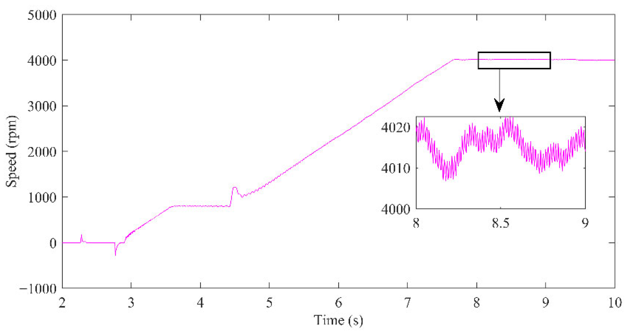
The experimental results demonstrate the precise control capabilities of the proposed SMO. As depicted in Figure 9, the motor achieved its target speed with a minimal steady-state speed fluctuation of only 20 rpm (ranging from 4000 to 4020 rpm) within 1 s (between t = 8 s and t = 9 s), highlighting the excellent dynamic response and stability of the system. Experimental evaluation further confirmed these advantages. At 4000 rpm, the proposed approach maintained speed fluctuations within 20 rpm (0.5% error), while q-axis current stabilized at 0.37 A and d-axis current stayed tightly bounded within ±0.05–0.07 A. During acceleration (1320→2365 rpm in 1 s), the control system exhibited synchronized current and speed tracking, validating robust transient performance. Under dynamic loading, speed deviations did not exceed ±5 rpm, demonstrating strong disturbance rejection. These results quantitatively establish the method’s precision, torque efficiency, and operational robustness under real-world compressor conditions. Furthermore, the d-axis current, as shown in Figure 10a, was meticulously maintained within a narrow band of ±0.05 to ±0.07 A, effectively ensuring precise flux weakening control during high-speed operation. The q-axis current, presented in Figure 10b, accurately reflected torque production, exhibiting a controlled peak during acceleration and settling to a stable 0.37 A in the steady-state, which is indicative of efficient torque generation and utilization.
During the acceleration phase, from approximately 4.7 s to 7.5 s, both the motor speed (Figure 11) and the q-axis current (Figure 10b) exhibited a rapid and consistent increase, signifying the robust transient performance of the control system. Specifically, within a 1 s interval (from 5 s to 6 s) during acceleration, the speed increased by 1045 rpm (from 1320 rpm to 2365 rpm), while the corresponding q-axis current transitioned from 0.23 A to 0.31 A. This synchronized behavior underscores the effectiveness of the SMO in accurately estimating rotor position and speed, enabling precise current control even during demanding dynamic transitions, which is crucial for optimizing the energy efficiency and reliability of air compressor systems. A frequency-domain analysis was conducted to quantitatively evaluate the chattering suppression performance of the proposed adaptive-gain SMO. The Fast Fourier Transform (FFT) of the rotor position estimation error (the difference between the estimated and encoder-measured position) at a steady-state speed of 4000 rpm is shown in Figure 11. The spectrum is dominated by a DC component corresponding to the average speed of 4004 rpm. The Total Harmonic Distortion (THD) of the position error is 0.28%, indicating negligible high-frequency content. This clean spectral profile, devoid of significant harmonics or high-frequency noise, provides direct evidence of effective chattering suppression, a key advantage of the proposed adaptive-gain mechanism over conventional SMO designs.

6. Conclusions

This study has developed and validated an EMF-based sliding mode observer with optimized gain scheduling for sensorless control of PMSM drives in air compressor applications. The proposed strategy demonstrated effective chattering mitigation and precise estimation capability across a wide operational range, achieving rapid acceleration from standstill to 7000 rpm within three seconds in simulations. The enhanced observer structure specifically addresses the operational demands of compressor systems, including frequent start-stop cycles and variable loading conditions. Comprehensive testing confirmed stable performance across the operational speed range with minimal steady-state errors and excellent disturbance rejection capabilities. Experimental validation on a 2.2 kW platform showed stable operation with precise current regulation, maintaining d-axis current within tight bounds. The consistent results across simulation and experimental domains establish the method as a reliable sensorless solution specifically tailored for industrial and automotive compressors, combining performance stability with practical implementation advantages. The proposed method’s limitations include degraded low-speed performance from weak back-EMF signals, sensitivity to stator resistance drift, and a marginally higher computational load than conventional observers. Future work will integrate a lead-lag compensator, predictive torque control, and a disturbance observer with the SMO to enhance robustness against thermal drift, parametric uncertainties, and load transients, thereby improving low-speed stability and overall fault tolerance. The proposed method delivers robust medium-to-high speed performance crucial for compressors, but its back-EMF-based approach is limited at very low speeds by a low signal-to-noise ratio and sensitivity to thermal parameter drift. Overall, the originality of this work lies in the adaptive-gain SMO design with refined back-EMF estimation, which ensures robust and practical sensorless control for compressor drives.

Author Contributions

Conceptualization, Methodology, software, validation, data curation, writing—original draft preparation, R.M.S.; software, visualization, W.W.; visualization, R.J.; resources, Z.F.; formal analysis, project administration, funding acquisition, K.L. All authors have read and agreed to the published version of the manuscript.

Funding

This research was funded by the Aero Science Foundation of China, grant number 20240007069003.

Data Availability Statement

The raw data supporting the conclusions of this article will be made available by the authors on request. The original contributions presented in the study are included in the article. Further inquiries can be directed to the corresponding author.

Conflicts of Interest

The authors declare no conflicts of interest.

References

  1. Jena, S.; Kumar, S.; Deshmukh, A.V.; Hava, A.M.; Akin, B.; Gabrys, C.; Rodgers, T. Design and Control of High-Frequency Buck Converter Fed Six-Step Drive for Air-Core PMSM. IEEE J. Emerg. Sel. Top. Power Electron. 2025, 13, 1144–1157. [Google Scholar] [CrossRef]
  2. Ha, V.T. Drive Control of a Permanent Magnet Synchronous Motor Fed by a Multi-level Inverter for Electric Vehicle Application. Eng. Technol. Appl. Sci. Res. 2022, 12, 8658–8666. [Google Scholar] [CrossRef]
  3. Yoon, K.-Y.; Lee, S.-T. Performance Improvement of Permanent-Magnet-Synchronous Motors through Rotor Shape Optimization of Marine Blowing System with High-Speed Rotation. Energies 2023, 16, 5486. [Google Scholar] [CrossRef]
  4. Wen, D.; Wang, W.; Zhang, Y. Sensorless Control of Permanent Magnet Synchronous Motor in Full Speed Range. Chin. J. Electr. Eng. 2022, 8, 97–107. [Google Scholar] [CrossRef]
  5. Chen, F.; Li, C.; Li, Z.; Du, Q.; Yin, W. Robust predictive torque control of switched reluctance motor based on linear extended state observer. Electr. Eng. 2024, 106, 7973–7984. [Google Scholar] [CrossRef]
  6. Dang, C.; Dou, M.; Yan, S.; Dang, M.; Wang, Y.; Zhao, D.; Hua, Z. An Improved Adaptive Sliding Mode Speed Control of PMSM Drives with an Extended State Observer. IEEE Trans. Energy Convers. 2024, 39, 2349–2361. [Google Scholar] [CrossRef]
  7. Dei, G.; Gupta, D.K.; Sahu, B.K.; Bajaj, M.; Blazek, V.; Prokop, L. A novel TID + IDN controller tuned with coatis optimization algorithm under deregulated hybrid power system. Sci. Rep. 2025, 15, 4838. [Google Scholar] [CrossRef]
  8. Akundi, S.S.; Braniff, A.; Dantas, B.; Liu, Y.; Tian, Y.; Niknezhad, S.S.; Khan, F.I.; Pistikopoulos, E.N. Chapter Eight—Advanced system control strategies for enhanced safety and efficiency of energy systems. In Methods in Chemical Process Safety; Khan, F.I., Pistikopoulos, E.N., Sajid, Z., Eds.; Elsevier: Amsterdam, The Netherlands, 2024; Volume 8, pp. 243–260. ISBN 9780443297748. [Google Scholar] [CrossRef]
  9. Jin, S.; Jin, W.; Wang, H.; Yu, S.; Zhang, Z. Maximum torque per ampere control of permanent magnet/reluctance hybrid rotor dual stator synchronous motor. IET Electr. Power Appl. 2024, 18, 1021–1032. [Google Scholar] [CrossRef]
  10. Khan, M.Y.A. A Review of Analysis and Existing Simulation Model of Three Phase Permanent Magnet Synchronous Motor Drive (PMSM). Control Syst. Optim. Lett. 2024, 2, 349–356. [Google Scholar] [CrossRef]
  11. Tarczewski, T.; Lisinski, H.; Grzesiak, L.M. Performance analysis of PMSM servo-drive with state feedback and hybrid position controllers. IEEE Trans. Ind. Electron. Res. 2025, 12, 100116. [Google Scholar] [CrossRef]
  12. Shuang, B.; Zhu, Z.-Q. Simultaneous Sensorless Rotor Position and Torque Estimation for IPMSM at Standstill and Low Speed Based on High-Frequency Square Wave Voltage Injection. IEEE Trans. Ind. Electron. 2022, 69, 8791–8802. [Google Scholar] [CrossRef]
  13. Rahman, S.U.; Xia, C. Rotor Speed and Position Estimation Analysis of Interior PMSM Machines in Low and Medium-High Speed Regions Adopting an Improved Flux Observer for Electric Vehicle Applications. Machines 2023, 11, 574. [Google Scholar] [CrossRef]
  14. Aminzadeh, A.; Sattarpanah Karganroudi, S.; Majidi, S.; Dabompre, C.; Azaiez, K.; Mitride, C.; Sénéchal, E. A Machine Learning Implementation to Predictive Maintenance and Monitoring of Industrial Compressors. Sensors 2025, 25, 1006. [Google Scholar] [CrossRef] [PubMed]
  15. Shokrani, A.; Dogan, H.; Burian, D.; Nwabueze, T.D.; Kolar, P.; Liao, Z.; Sadek, A.; Teti, R.; Wang, P.; Pavel, R.; et al. Sensors for in-process and on-machine monitoring of machining operations. CIRP J. Manuf. Sci. Technol. 2024, 51, 263–292. [Google Scholar] [CrossRef]
  16. Wang, Y.; Hu, Q.; Li, K. Fault-Tolerant Control of PMSM Drives Under Sensor Failures for Aerospace Applications. IEEE Trans. Transp. Electrif. 2022, 8, 2055–2067. [Google Scholar]
  17. Beheshti Asl, M.; Fofana, I.; Meghnefi, F. Review of Various Sensor Technologies in Monitoring the Condition of Power Transformers. Energies 2024, 17, 3533. [Google Scholar] [CrossRef]
  18. Yue, W.; Guo, Y.; Lee, J.; Ganbold, E.; Wu, J.-K.; Li, Y.; Wang, C.; Kim, H.S.; Shin, Y.-K.; Liang, J.-G.; et al. Advancements in Passive Wireless Sensing Systems in Monitoring Harsh Environment and Healthcare Applications. Nano-Micro Lett. 2025, 17, 106. [Google Scholar] [CrossRef] [PubMed]
  19. Chen, B.; Chen, F. Sensorless Control of PMSM Based on an Improved Super-Twisting Sliding Mode Observer. J. Electrotechnol. Electr. Eng. Manag. 2025, 8, 45–54. [Google Scholar] [CrossRef]
  20. Sumika, C.; Govind, V.; Radoslaw, Z. Analysing Recent Breakthroughs in Fault Diagnosis through Sensor: A Comprehensive Overview. Comput. Model. Eng. Sci. 2024, 141, 1983–2020. [Google Scholar] [CrossRef]
  21. Huang, Y.; Su, Z.; Chang, D.; Sun, Y.; Tan, J. Error Analysis of an Economical On-Site Calibration System for Linear Optical Encoders. Metrology 2024, 4, 131–140. [Google Scholar] [CrossRef]
  22. Sun, H.; Zhang, X.; Liu, X.; Su, H. Adaptive Robust Sensorless Control for PMSM Based on Improved Back EMF Observer and Extended State Observer. IEEE Trans. Ind. Electron. 2024, 71, 16635–16643. [Google Scholar] [CrossRef]
  23. Liu, X.; Wang, Z.; Wang, W.; Lv, Y.; Yuan, B.; Wang, S.; Li, W.; Li, Q.; Zhang, Q.; Chen, Q. SMO-Based Sensorless Control of a Permanent Magnet Synchronous Motor. Front. Energy Res. 2022, 10, 839329. [Google Scholar] [CrossRef]
  24. Ran, Y.; Qiao, M.; Sun, L.; Xia, Y. Review of Position Sensorless Control Technology for Permanent Magnet Synchronous Motors. Energies 2025, 18, 2302. [Google Scholar] [CrossRef]
  25. Ferdiansyah, I.; Hanamoto, T. An Improved Extraction Scheme for High-Frequency Injection in the Realization of Effective Sensorless PMSM Control. World Electr. Veh. J. 2025, 16, 326. [Google Scholar] [CrossRef]
  26. Cao, X.; Ye, Y.; Duan, Y.; Wu, Y.; Yang, X. Sensorless control of permanent magnet synchronous motor based on adaptive back-EMF observer. Adv. Mech. Eng. 2023, 15, 168781322311516. [Google Scholar] [CrossRef]
  27. Yao, G.; Yang, Z.; Han, S.; Wang, Z. Full-speed domain position sensorless control strategy for PMSM based on a novel phase-locked loop. Control Eng. Pract. 2024, 152, 106058. [Google Scholar] [CrossRef]
  28. Xu, Y.; Lin, C.; Xing, J.; Zhang, H.; Zhuang, X. Robustness Enhancement of Position Sensorless Super-High-Speed Pmsm for Hydrogen Fuel Cell Air Compressors Based on Linear Extended State Observer. Appl. Energy 2025, 400, 126560. [Google Scholar] [CrossRef]
  29. Rahman, S.U.; Xia, C.; Shah, S.H.; Abubakar, U.; Hassan, M.U. Improving the Low-Speed Operation Performance of IPMSM Sensorless Vector Control with ADRC DC-Offset Compensation Loop. Eng. Proc. 2023, 46, 17. [Google Scholar] [CrossRef]
  30. Xu, S.; Shen, A.; Zhang, M.; Tang, Q.; Luo, X.; Xu, J. Dual-Sliding-Mode-Observer-Based IPMSM Sensorless Control Technique. Complexity 2024, 2024, 5512231. [Google Scholar] [CrossRef]
  31. Wei, X.; Mei, K.; Ding, S.; Jiang, L. Sensorless control of permanent magnet synchronous motor based on fixed-time terminal sliding mode observer. Asian J. Control 2024, 26, 1771–1786. [Google Scholar] [CrossRef]
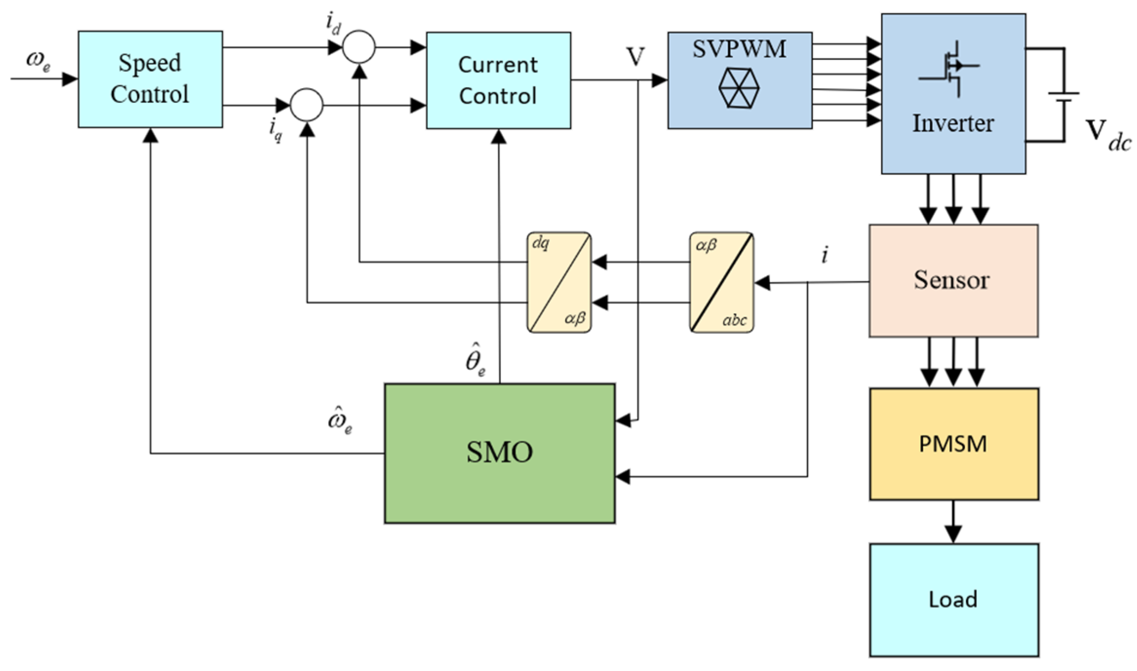
Figure 1. Block diagram of SMO-based sensorless control of PMSM Drive.
Applsci 15 11206 g001
Figure 2. Different reference frames in a PMSM drive.
Applsci 15 11206 g002
Figure 3. Simulation results at 2000 rpm: (a) Stator currents [A]; (b) Rotor speed tracking [rpm].
Applsci 15 11206 g003
Figure 4. Simulation results at 4000 rpm: (a) Stator currents [A]; (b) Rotor speed tracking [rpm].
Applsci 15 11206 g004
Figure 5. Simulation results at 7000 rpm: (a) Stator currents [A]; (b) Rotor speed tracking [rpm].
Applsci 15 11206 g005
Figure 6. Simulation results at 8500 rpm: (a) Stator currents [A]; (b) Rotor speed tracking [rpm].
Applsci 15 11206 g006
Figure 7. The stator current harmonic spectra across the operational speed range: (a) 2000 rpm; (b) 4000 rpm; (c) 7000 rpm; (d) 8500 rpm.
Applsci 15 11206 g007aApplsci 15 11206 g007b
Figure 8. Experimental setup: 2.2 kW PMSM compressor with DSP controller.
Applsci 15 11206 g008
Figure 9. Experimental speed at 4000 rpm [rpm].
Applsci 15 11206 g009
Figure 10. Experimental currents at 4000 rpm: (a) d-axis [A]; (b) q-axis [A].
Applsci 15 11206 g010
Figure 11. Frequency spectrum of rotor position estimation error demonstrating chattering suppression at 4000 rpm.
Applsci 15 11206 g011
Table 1. PMSM Parameters Used in Simulation.
Name of the ParameterParameter Value
Stator Resistance (Rs)0.00031 Ω
Stator Inductance (Ls)0.445 mH
Permanent Magnet Flux Linkage (ψf)0.00954 Wb
Sampling Time (Ts)0.0001 ns
Viscous Damping Coefficient (B)0.000213 N·m·s/rad
Simulation Step Size5 × 10−7 ns
Rotor Moment of Inertia (J)2.8 × 10⁻⁷ kg·m2
Number of poles (Pn)4
Disclaimer/Publisher’s Note: The statements, opinions and data contained in all publications are solely those of the individual author(s) and contributor(s) and not of MDPI and/or the editor(s). MDPI and/or the editor(s) disclaim responsibility for any injury to people or property resulting from any ideas, methods, instructions or products referred to in the content.