1. Introduction
In recent years, environmental problems such as global warming, ozone layer depletion, and climate change have become increasingly prominent, drawing greater attention to energy conservation issues. Currently, commercial and residential buildings account for approximately 30% to 40% of total global energy consumption [
1]. Among these, air conditioning systems alone consume about 50% of the total building energy to maintain comfortable indoor temperatures [
2]. In building design, heat loss through the building envelope contributes significantly to overall energy consumption, with transparent components such as glass windows, curtain walls, and glass roofs accounting for approximately 40% of this loss [
3]. Due to direct solar radiation penetration, these components significantly increase indoor heat loads, becoming critical areas for thermal energy management. In the design of passive energy-efficient buildings, enhancing the optical and thermal regulation performance of glass components has become a focal point for research and application [
4,
5].
To achieve energy-efficient passive window designs, glazing must exhibit selective spectral response characteristics across the solar spectrum. Visible light (~400–700 nm) is required for indoor illumination and visual comfort, whereas near-infrared (~700–1500 nm) is responsible for radiative heating. Notably, about 90% of solar energy lies in the 400–1500 nm range, encompassing both VIS and NIR [
6]. For green building applications, the main optical performance indicators are the Visible Light Transmittance (VLT) and the Solar Heat Gain Coefficient (SHGC). In general, a VLT above 60% is desired to ensure sufficient daylighting, although it may be slightly reduced when prioritizing thermal insulation. For SHGC, values below 0.3 are typically required. To meet both criteria simultaneously, the glazing design must maximize VIS transmittance while minimizing NIR transmittance, which is precisely the performance objective of this study.
Currently, several advanced glass technologies are considered effective in improving the thermal insulation performance of windows, thereby reducing building energy loss. For instance, multi-layer glass structures, combined with low-emissivity coatings or filled with insulating materials in the interlayer, can achieve high thermal resistance; however, this leads to thicker and heavier structures, which are less favored by users [
7,
8]. Vacuum glazing achieves excellent thermal insulation with thin designs, but its high manufacturing cost and durability in maintaining vacuum remain concerns [
9]. Transparent insulating materials (TIM) such as transparent aerogels, transparent polymer foams, and capillary structures filled between multi-layer glass panes effectively improve thermal insulation but adversely affect transparency and reduce visual comfort [
10,
11,
12,
13]. Thermochromic and photochromic glasses, which incorporate specialized thin-film coatings, adaptively regulate indoor solar radiation and optical properties [
14,
15]. However, these glasses typically have relatively low VIS light transmittance and are mainly utilized in hot climates. Moreover, they usually modulate solar radiation through absorption, leading to heat accumulation within the glass, which eventually transfers into the interior space. Photovoltaic (PV) glass integrates thermal insulation with power generation by embedding thin-film PV cells or partially embedding silicon-based PV cells to convert some solar energy into electricity, thereby reducing indoor solar heat gain [
16,
17]. However, due to the heat accumulation from solar radiation absorbed by PV cells, additional insulation design is required, resulting in heavier structures and higher costs.
Compared to the aforementioned complex glass structures, single-layer glass is extensively used in building windows due to its thin, lightweight nature, and low cost. However, most single-layer glass types exhibit poor infrared blocking capabilities. Therefore, there is a strong demand for a low-cost, single-layer glass technology that offers effective NIR blocking performance and high VIS light transmittance.
Metasurfaces, artificial materials composed of subwavelength nanostructures, exhibit unique optical properties allowing precise control of light propagation direction and intensity. By adjusting geometric structures, metasurfaces selectively modulate transmittance, reflectance, and absorptance at different wavelengths. Therefore, designing appropriate metasurfaces on glass surfaces can effectively reflect infrared radiation, reducing heat entry indoors and lowering air conditioning load, while maintaining high VIS transmittance and indoor natural illumination. Previous studies demonstrated broadband all-dielectric metamaterials based on silicon resonators achieving over 98% NIR reflectance between 1350–1550 nm [
18]. Another design, based on single-crystal diamond resonators, attained over 99.99% reflectance at 795 nm with extremely low absorption, though limited by narrow operational bandwidth [
19]. To extend the operational spectral range, all-dielectric structures composed of TiO
2 and ITO were shown to block 90% of NIR while maintaining approximately 70% VIS transmittance, highlighting their potential for energy-efficient building applications [
20].
Subsequent studies gradually improved infrared blocking efficiency and bandwidth control. Photonic multilayer structures further enhanced NIR shielding performance [
21]. Designs employing two-dimensional tungsten nanoring arrays achieved 87% NIR reflectance while maintaining 60% VIS transmittance, emphasizing geometric importance in spectral selectivity [
22]. Moreover, metasurfaces with asymmetric structures have been proposed, providing optical selectivity adaptable to seasonal changes, demonstrating potential for smart window applications [
23].
Beyond optical performance, recent research has increasingly focused on the multifunctional integration of metasurfaces, including radio frequency (RF) transmission and thermal radiation control. Specifically designed meta-glass exhibited 92% RF transmittance at 30 GHz, alongside low thermal emissivity and high NIR reflectance, indicating potential applications in energy saving and 5G communications [
24]. Simple fabrication processes, such as single-layer metal deposition and transfer printing techniques, enabled cross-shaped structures achieving 77.2% VIS transmittance and 86.1% NIR reflectance, alongside high transmission in the terahertz frequency range, demonstrating forward-looking potential for future 6G applications [
25]. Further research integrated existing low-E glass with metasurfaces to enhance microwave transmission, combining building energy efficiency with wireless communication functionality [
26]. Additionally, dielectric-grid-based concentrators designed to guide NIR radiation to window edges for power generation, while supporting daylighting and mitigating urban heat island effects, expanded metasurface applications in sustainable urban buildings [
27].
In summary, metasurfaces exhibit tremendous potential and broad prospects in energy-efficient glazing applications for buildings, owing to their exceptional spectral regulation capability, multifunctional integration, and fabrication flexibility. Most previous studies, however, have focused on single-sided metasurface coatings, leaving the interactions between two metasurfaces across a glazing panel largely unexplored. To address this gap, the present study proposes two double-sided metasurface glass designs: one oriented toward maintaining high visible transmittance while reducing NIR transmission, and the other toward enhancing NIR blocking with acceptable visible transmittance. The metasurfaces are systematically optimized using Rigorous Coupled-Wave Analysis (RCWA), and their optical responses are integrated into a glazing model through a cross-scale workflow that couples electromagnetic wave simulations with ray-tracing analysis. This enables accurate evaluation of angular performance under realistic solar illumination. In addition, the potential of the designs to partially suppress harmful deep blue (400–450 nm) light is also assessed.
2. Design Principles, Models, and Methods
This section introduces the overall framework of the study. It first explains the design principles and models of the proposed metasurfaces, followed by a description of the simulation methods used to evaluate their optical performance.
2.1. Design Principles
When light is normally incident upon an interface, the interface reflectance R is the squared magnitude of the interface reflection coefficient
r, which can be expressed as in Equation (1):
Here, the complex impedance z of the medium is defined as z = z′ +
jz″, where z′ and z″ are the real and imaginary parts of z, respectively. The impedance z is related to permittivity (ε) and permeability (μ), as shown in Equation (2):
From Equation (1), it can be observed that the reflectance R approaches unity as z′ approaches zero. Specifically, perfect reflection (R = 1) occurs when z′ = 0. The necessary condition for achieving z′ = 0 is that either ε′ or μ′ is negative given by Equation (3):
Both metamaterials and metasurfaces can exhibit negative permittivity or permeability, primarily due to their specially designed microstructures that respond resonantly to electromagnetic waves at certain frequencies. These microstructures enable polarization responses opposite to the external electric field direction, thus resulting in negative permittivity. Alternatively, when the frequency of an applied magnetic field matches the resonance frequency of these structures, the internal magnetic dipole moments can oppose the applied magnetic field, resulting in negative permeability. Furthermore, in certain artificial structures or media, surface plasmon–polariton phenomena can also lead to negative permeability. Therefore, by carefully designing the subwavelength microstructures and selecting appropriate material combinations, the reflection spectra of metasurfaces can be precisely tuned to meet specific design objectives.
Metasurfaces constructed from high-index dielectrics such as TiO2 (as well as other common high-index materials like Si and GaN) can support Mie-type resonances, including both electric and magnetic dipole modes. When high transparency in the visible range is desired, TiO2 is particularly advantageous due to its high refractive index (~2.5 at 550 nm), low absorption loss, and excellent fabrication compatibility, making it the most widely used dielectric material for visible-transparent metasurfaces. By tuning the nanocylinder dimensions, these resonances can be engineered to produce strong reflection at target wavelengths while avoiding absorption in the VIS range, thereby maintaining high visible transmittance. In contrast, metal–insulator–metal (MIM) structures combine plasmonic and cavity effects. The strong coupling between the incident electric field and free electrons on the metallic surface excites surface plasmon polaritons, while the dielectric spacer and metal layers together form a Fabry–Pérot cavity. The optical behavior of the metallic layers is governed by their complex permittivity: a large negative real part (Re{ε} ≪ 0) provides high reflectivity, whereas the imaginary part (Im{ε}) determines intrinsic absorption across the VIS–NIR spectrum. Typical metallic materials used in MIM configurations include Ag, Au, and Al. Among these, Ag is the most widely adopted because it combines a very negative real permittivity with a relatively small imaginary part in the visible and near-infrared ranges, yielding strong reflectivity with comparatively low absorption losses. MIM metasurfaces are therefore highly sensitive to structural parameters but exhibit superior angular tolerance. However, their inherent absorption limits visible transmittance, which is undesirable for glazing. To overcome this, we adopt a modified MIM configuration by replacing the top metallic nanostructure with a dielectric TiO2 layer. This dielectric–insulator–metal (DIM) design improves impedance matching at the air–structure interface, enhancing VIS transmission while preserving strong NIR blocking capability.
2.2. Design Models
In this study, we design the glazing by combining two metasurfaces on opposite sides of the glass to enhance near-infrared (NIR) suppression and broaden the effective reflection bandwidth beyond what a single layer can achieve. Based on the distinctive characteristics of all-dielectric and DIM metasurfaces, we propose two insulating glass configurations.
Design I consists of two all-dielectric metasurfaces: the front surface is tuned to reflect shorter-wavelength NIR while maintaining high visible transmittance, and the back surface is optimized to suppress longer-wavelength NIR, thereby providing complementary coverage across the NIR spectrum. This configuration is therefore expected to favor higher visible transmittance, though its NIR blocking capability may be relatively weaker. Both metasurfaces consist of cylindrical TiO
2 microstructures fabricated on a fused silica (SiO
2) substrate, as illustrated in
Figure 1a. By adjusting microstructure dimensions, the outward-facing front metasurface is designed to reflect incident NIR radiation in the wavelength range of 700–800 nm while maintaining acceptable VIS transmittance; the inward-facing back metasurface is optimized to reflect incident NIR radiation between 800–1500 nm.
Design II, by contrast, integrates a DIM metasurface on the outward-facing front side, leveraging its enhanced NIR reflection and angular tolerance, while the inward-facing back side employs an all-dielectric metasurface to further suppress residual NIR. This configuration is anticipated to provide stronger overall NIR suppression, but with some reduction in visible transmittance. The DIM metasurface comprises TiO
2 cylindrical microstructures, an insulating layer (SiO
2), a silver (Ag) layer, and a fused silica substrate, as depicted in
Figure 1b. The back-side metasurface is similar to that shown in
Figure 1a and further optimized to enhance reflection of NIR light in the 700–900 nm range through precise control of the microstructure dimensions.
Together, these two designs illustrate how Mie- and Fabry–Pérot-based meta-atoms can be strategically combined in double-sided architectures to realize energy-efficient glazing with improved spectral control. The detailed simulation workflow used to evaluate these designs is presented in the following
Section 2.3.
2.3. Methods
To accurately evaluate the optical performance of the proposed double-sided metasurface glazing, we established a cross-scale modeling framework that couples electromagnetic wave simulations with ray-tracing analysis. This methodology enables realistic assessment of angular- and wavelength-dependent responses, particularly the multiple reflections and diffractions occurring between two metasurfaces at incoherent distances, which cannot be captured by a simple product of single-surface transmittances. Beyond the numerical workflow, the methodology also incorporates key engineering aspects, including meta-atom selection, material choice, structural optimization, and performance assessment under varying solar incidence angles. Two distinct design configurations were investigated to represent different performance priorities, acknowledging that optimal solutions in engineering practice often reflect compromises tailored to specific application requirements.
The computational procedure is summarized as follows. Since a metasurface is a periodic array of meta-atoms, the electromagnetic model was constructed using a unit-cell representation of a single meta-atom. The geometry, parameters, and simulation domain are illustrated in
Figure 1, where the purple box indicates the simulation domain and the orange bar on the top boundary represents the plane-wave light source. Electromagnetic simulations were performed using the commercial software RSoft DiffractMOD version 2023.12 (Synopsys Inc., Burnaby, BC, Canada), which implements the RCWA method. An initial parametric sweep of the meta-atom dimensions was carried out to obtain transmission, reflection, and absorption spectra, and the resulting optimal ranges were further refined by applying the AM1.5 solar spectrum as a weighting function to determine the final geometries.
To bridge the electromagnetic and ray-tracing domains, the Bi-directional Scattering Distribution Function (BSDF) utility within DiffractMOD was employed to calculate the metasurface response across incident angles from 0° to 90° and wavelengths from 400–1500 nm. The BSDF includes transmission, reflection, and absorption contributions of all diffraction orders for both TE and TM polarizations, considering illumination from either side of the metasurface. The generated BSDF data were then imported into the commercial ray-tracing software LightTools version 2024.03 (Synopsys Inc.), where a glazing model was constructed with metasurface responses assigned to both front and back surfaces. By applying an AM1.5 solar source at incidence angles ranging from 0° to 85°, the spectral transmission of the double-sided glazing was computed, enabling quantitative evaluation of angle-dependent optical performance. A summary of this computational workflow is presented in the flow chart shown in
Figure 2.
3. Simulation Results and Discussion
Since solar energy within the 400–1500 nm wavelength range accounts for nearly 90% of the total energy in the AM 1.5 solar spectrum, this study focuses on optimizing selective transmission and reflection within this spectral range. To enhance thermal insulation performance, we aim to maximize the spectral blocking range and efficiency. Considering that the luminous efficacy of the 650–700 nm band is relatively low—contributing less to perceived brightness because of its lower weighting in the photopic response function—this study extends the target NIR blocking range from the conventional 700–1500 nm to 650–1500 nm. Additionally, since light in the 400–450 nm range is classified as harmful blue light, the desired visible transmission band is narrowed from the typical 400–700 nm to 450–650 nm, with the 400–450 nm range defined as the DB band. The primary optimization objective is therefore to minimize the transmittance of both DB and NIR light, while maintaining as much VIS light transmittance as possible. To ensure the reliability of the numerical results, a convergence analysis was conducted as a basic requirement of RCWA simulations. The number of harmonic terms was gradually increased until the transmission spectra became stable. As shown in
Figure A1 (
Appendix A), the spectra of the first type of meta-atom converged at 9 harmonics (corresponding to 19 Fourier components in 1D, 19 × 19 in 2D), while both transmission and reflection of the second type converged at the same number. For consistency and accuracy, all calculations were subsequently performed with 11 harmonics for the first type and 15 harmonics for the second type because the latter, which includes a metal layer, may exhibit slower convergence under certain conditions. Moreover, the materials used in the models—TiO
2, SiO
2, and Ag—were all taken from the built-in wavelength-dependent database provided by the RSoft software, ensuring realistic dispersion properties in the simulations.
3.1. Optimization of Design I
Before commencing the optimization process, preliminary trials and evaluations of the relevant parameters were conducted to determine suitable initial values and scanning ranges, as these factors critically influence the quality of the subsequent optimization results. Since these procedures are relatively lengthy and fragmented, they are omitted in this paper. For the front-side microstructures, preliminary simulation estimates indicated that the optimization ranges for pitch, diameter, and height were approximately 350–550 nm, 160–360 nm, and 375–525 nm, respectively.
The optimization process began with the microstructure pitch, with the diameter and height fixed at 260 nm and 450 nm, respectively. As shown in
Figure 3a, reducing the pitch shifts the wavelength of perfect reflection (i.e., transmittance = 0) toward shorter values, which may also induce partial high reflection in the visible range and narrow the high-reflection bandwidth. Considering the design objective of balancing visible light transmittance with low transmittance in the 700–800 nm range, a pitch of 500 nm was considered the most appropriate choice.
With the pitch and height fixed at 500 nm and 450 nm, respectively, the microstructure diameter was then optimized.
Figure 3b shows that when the diameter is below 210 nm, perfect reflection does not occur. Increasing the diameter shifts perfect reflection to longer wavelengths but reduces VIS light transmittance. A diameter of 260 nm achieved the lowest transmittance within the 700–800 nm range while maintaining acceptable visible transmittance, making it the most appropriate choice.
Subsequently, the microstructure height was optimized with the pitch and diameter fixed at 500 nm and 260 nm, respectively. As shown in
Figure 3c, Increasing the microstructure height results in a narrower high-reflection bandwidth and higher VIS transmittance, while the height has minimal influence on the NIR transmittance. A height of 450 nm produced a relatively broad reflection bandwidth in the 700–800 nm range while preserving VIS transmittance, satisfying the design objectives.
From the preceding parameter sweeps, the first-stage design values were determined as pitch = 500 nm, diameter = 260 nm, and height = 450 nm. These values were used as the initial conditions for a second optimization stage, in which spectral weighting—based on the AM 1.5 solar spectrum—was incorporated, as detailed in
Appendix B. The resulting optimal parameters were pitch = 470 nm, diameter = 285 nm, and height = 420 nm (
Figure 3d). The dashed and solid lines in
Figure 3d represent the results before and after optimization, respectively. The VIS transmittance remained largely unchanged, while the DB transmittance decreased, and NIR reflectance in the 700–1000 nm range increased.
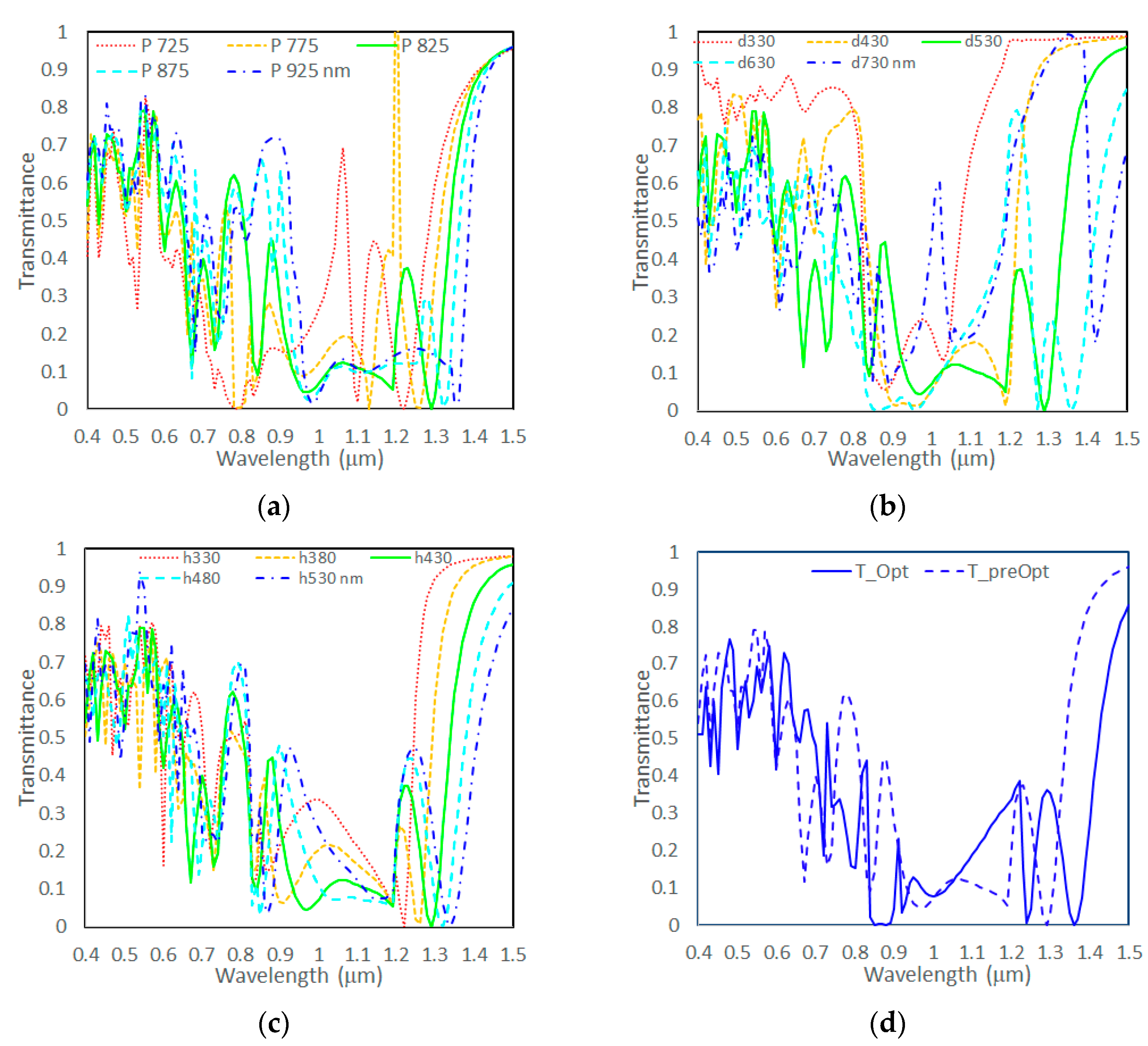
Similarly, for the back-side microstructures, preliminary simulations were conducted to estimate suitable parameter ranges, yielding approximate optimization intervals of 725–925 nm for pitch, 330–730 nm for diameter, and 330–530 nm for height. Parameter sweeps were then performed within these ranges to examine the effects of each parameter on transmission spectra.
The pitch optimization was first carried out by fixing the height and diameter at 430 nm and 530 nm, respectively. As shown in
Figure 4a, VIS transmittance generally increases with larger pitch; however, a larger pitch also results in increased transmittance in the NIR range of 800–1000 nm. Considering the need to balance VIS transmittance with NIR reflectance, a pitch of 825 nm was considered the most appropriate choice.
Next, the diameter optimization was performed with the pitch and height fixed at 825 nm and 430 nm, respectively. As shown in
Figure 4b, smaller diameters lead to higher VIS transmittance, but also increase the transmittance in the NIR range of 1100–1500 nm. A diameter of 530 nm was identified as the most appropriate choice to balance VIS transmittance and NIR reflectance.
Subsequently, the height optimization was conducted by fixing the pitch and diameter at 825 nm and 530 nm, respectively. As illustrated in
Figure 4c, taller microstructures slightly improve visible light transmittance but also increase NIR transmittance in the 800–1000 nm range. A height of 430 nm was selected as the most appropriate choice to meet the design requirements.
From the preceding parameter sweeps, the first-stage design values were determined as pitch = 825 nm, diameter = 530 nm, and height = 430 nm. These values were then used as the initial conditions for a second round of optimization, incorporating spectral weighting based on the AM 1.5 solar spectrum. The optimal parameters obtained were pitch = 840 nm, diameter =600 nm, and height = 445 nm, with the results shown in
Figure 4d. In
Figure 4d, the dashed and solid lines represent the transmission spectra before and after optimization, respectively. Post-optimization, VIS transmittance increased slightly, DB transmittance was notably reduced, and NIR transmittance in the 700–1500 nm range remained largely unchanged.
3.2. Optimization of Design II
From previous studies, it is known that a thinner metal layer favors higher VIS transmittance but also increases NIR transmittance. Considering fabrication constraints, the initial metal layer thickness was set to 15 nm. The influence of the insulating layer thickness is less pronounced, and its initial value was set to 35 nm; however, due to interference-induced fluctuations in transmittance and reflectance, this parameter was also refined in the final optimization.
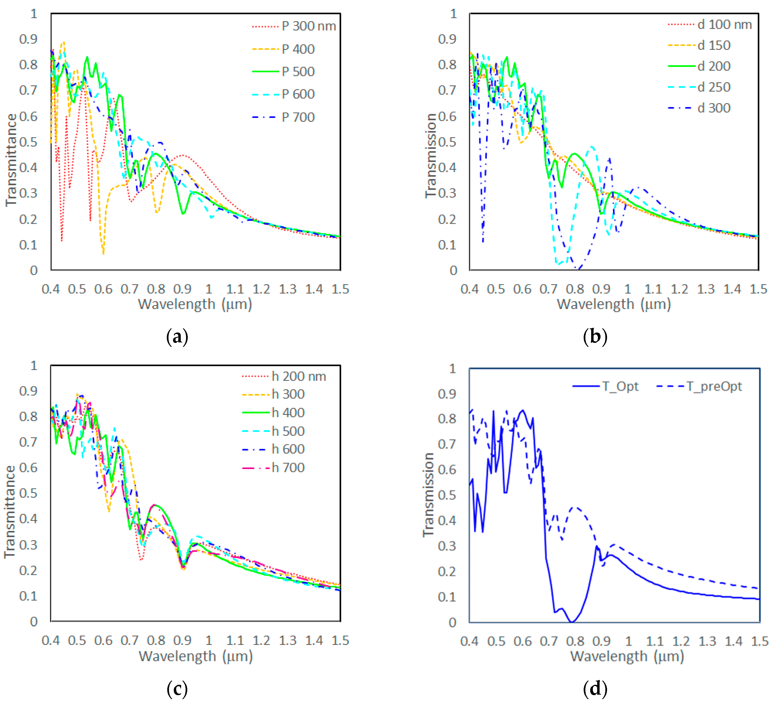
For the front-side microstructures, preliminary simulations indicated that suitable parameter ranges for the pitch, diameter, and height were approximately 300–700 nm, 100–300 nm, and 200–700 nm, respectively. Parameter sweeps were performed within these ranges to examine the effect of each parameter on the transmission spectra.
Pitch optimization was first conducted with the diameter and height fixed at 200 nm and 400 nm, respectively. As shown in
Figure 5a, pitches of 500 nm and 600 nm yielded higher VIS transmittance, but the 600 nm pitch exhibited higher NIR transmittance in the 700–1000 nm range. Therefore, a pitch of 500 nm was considered the most appropriate choice.
Next, diameter optimization was performed with the pitch and height fixed at 500 nm and 400 nm, respectively. As shown in
Figure 5b, diameters between 100 nm and 250 nm provided relatively high VIS transmittance, with 200 nm offering the additional benefit of lower NIR transmittance. Thus, a diameter of 200 nm was selected.
Height optimization was then carried out with the pitch and diameter fixed at 500 nm and 200 nm, respectively. As shown in
Figure 5c, transmittance was less sensitive to height compared to pitch and diameter. Considering fabrication feasibility, a lower microstructure height was preferred. A height of 400 nm was chosen, as it provided lower transmittance near 750 nm in the NIR region while maintaining acceptable VIS light transmittance.
From this parameter sweep, the first-stage design values were determined as pitch = 500 nm, diameter = 200 nm, and height = 400 nm. These values were used as the initial conditions for a second optimization stage, which incorporated spectral weighting based on the AM 1.5 solar spectrum and also included fine-tuning of the Ag layer and insulating layer thicknesses. The final optimal parameters were pitch = 490 nm, diameter = 300 nm, height = 325 nm, with the Ag and insulating layer thicknesses set to 19 nm and 55 nm, respectively. The simulation results are shown in
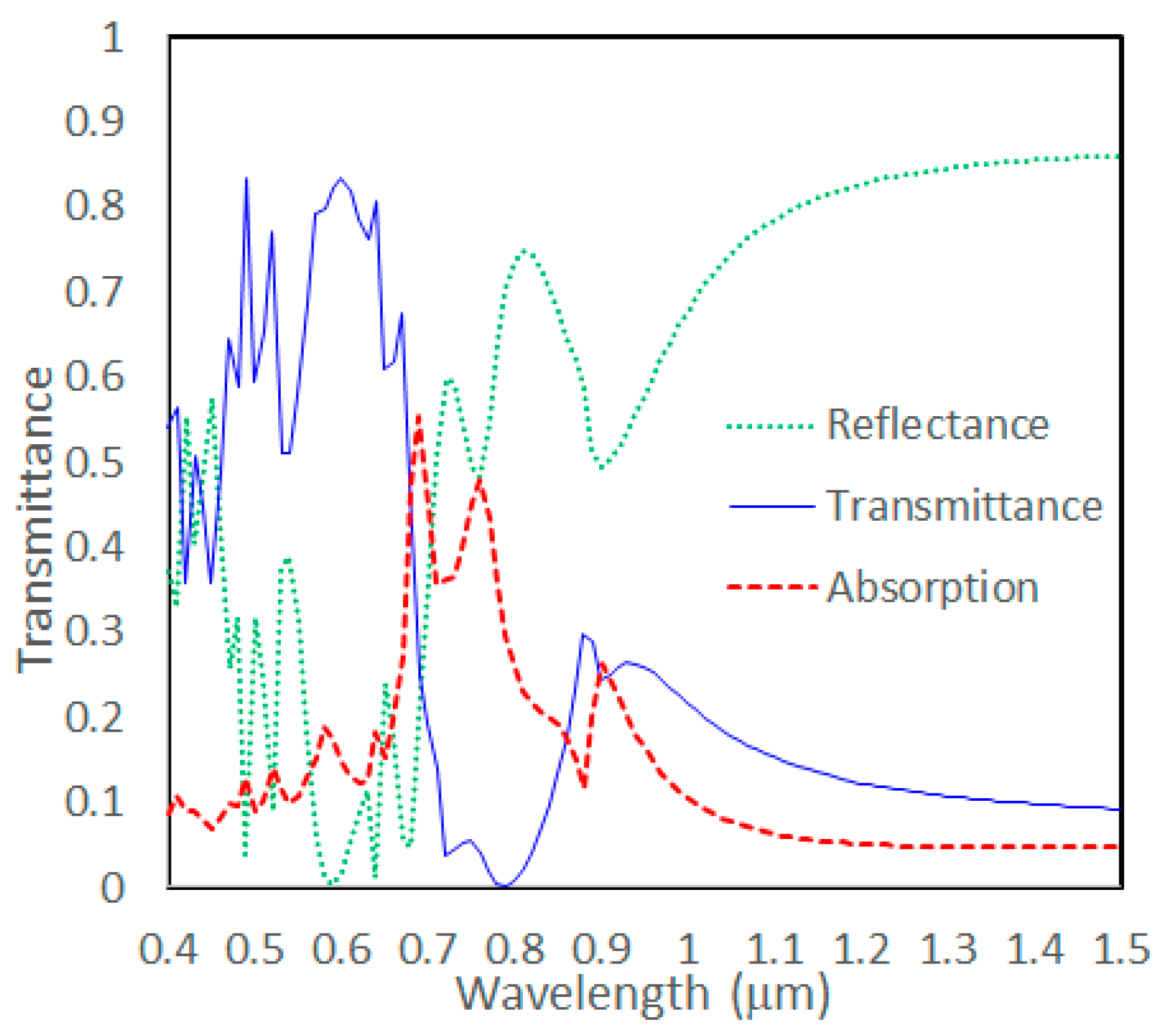
Figure 5d, where the dashed and solid lines represent the transmission spectra before and after optimization, respectively. Post-optimization, VIS transmittance showed a slight improvement, DB transmittance was reduced, and NIR transmittance in the 800–900 nm range was significantly decreased. Since this front-side includes a metallic layer, absorption is non-negligible. For completeness, the transmittance, reflectance, and absorption spectra of this metasurface are provided in
Figure A2 of the
Appendix A.
In Design II, the back side retained the same all-dielectric microstructure design as the back side of Design I, serving to reflect NIR. However, because the front side of Design II exhibits very low transmittance in the 800–900 nm NIR range, the back-side microstructure design focused on reducing NIR transmittance at wavelengths above 900 nm while improving VIS transmittance.
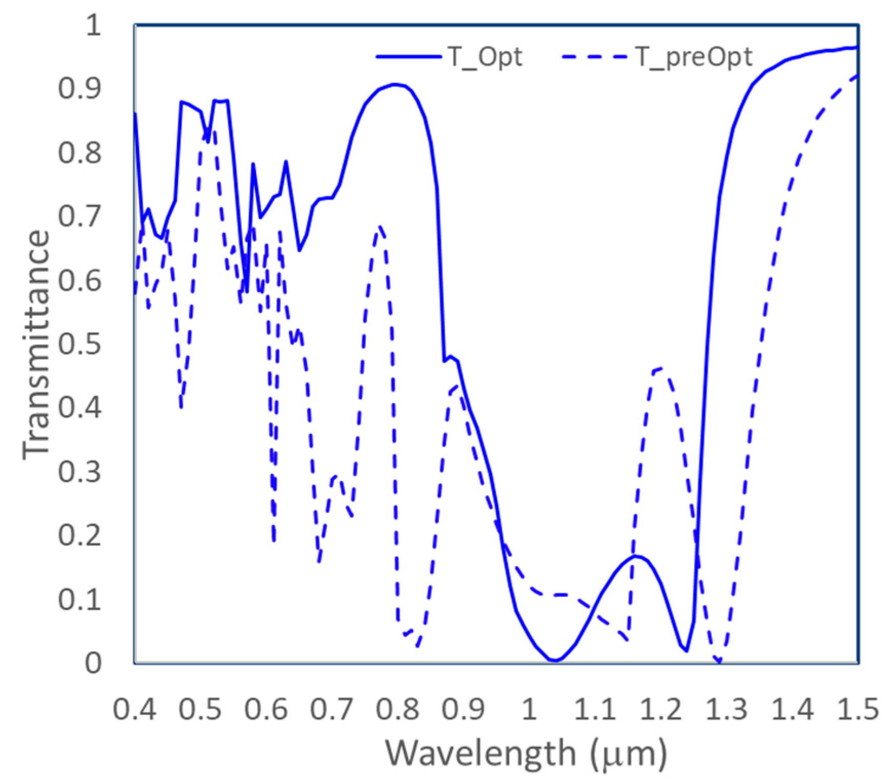
Starting from the optimized parameters of the Design I back side (P = 795 nm, d = 520 nm, h = 480 nm), optimization was performed with AM 1.5 spectral weighting, yielding the optimal parameters P = 870 nm, d = 420 nm, and h = 545 nm. The simulation results are shown in
Figure 6. As observed in
Figure 5, the optimized microstructure significantly increased VIS transmittance, but also reduced NIR blocking performance, particularly with noticeable increases in transmittance in the 700–900 nm and 1250–1500 nm bands. However, because the DIM metasurface on the front side of Design II already exhibits very low transmittance in the 800–900 nm range, the amount of energy reaching the back side in this spectral region is minimal. Similarly, the 1250–1500 nm range also experiences low transmittance through the front side, and its energy contribution in the solar spectrum is small. Consequently, the overall NIR transmittance of Design II remains at a low level.
3.3. Performance Evaluation
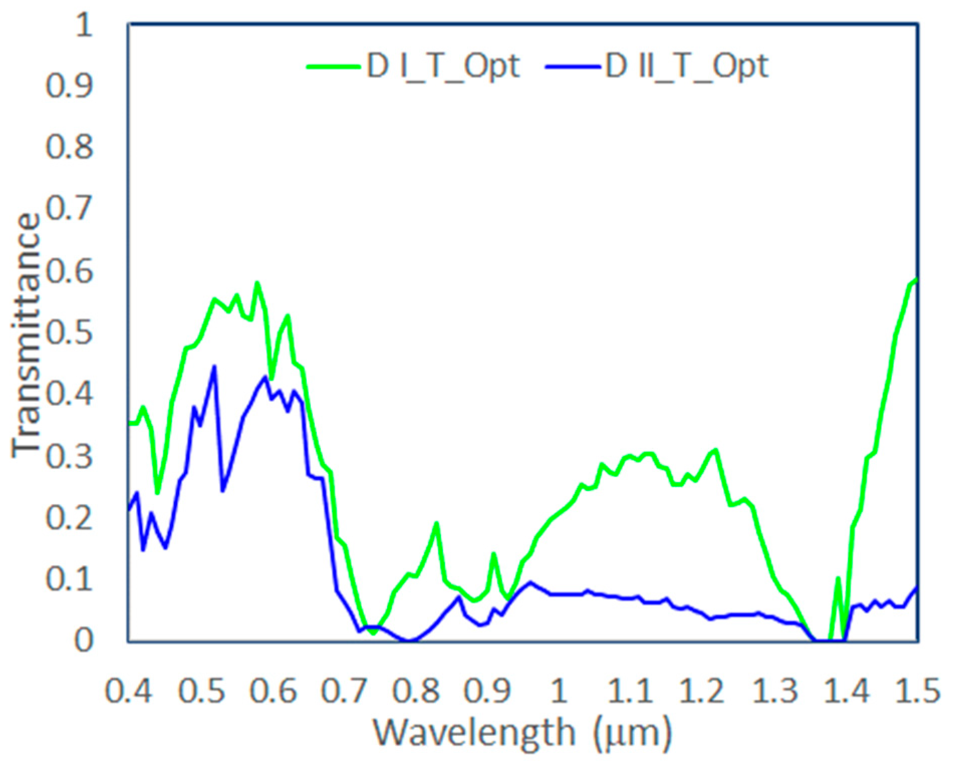
To accurately evaluate the insulation performance of double-sided metasurface glass, the bi-directional scattering distribution function (BSDF) was simulated individually for each metasurface, and subsequently, the transmittance spectra for both metasurface glass designs under normal incidence (0°) were calculated. The simulation results are shown in
Figure 7. As observed from the figure, Design I exhibits higher VIS transmittance but also higher NIR transmittance. In contrast, Design II displays slightly lower VIS transmittance but significantly lower NIR transmittance compared to Design I. Therefore, Design II achieves the intended goal of substantially improving insulation performance by sacrificing some VIS transmittance to significantly reduce NIR transmittance.
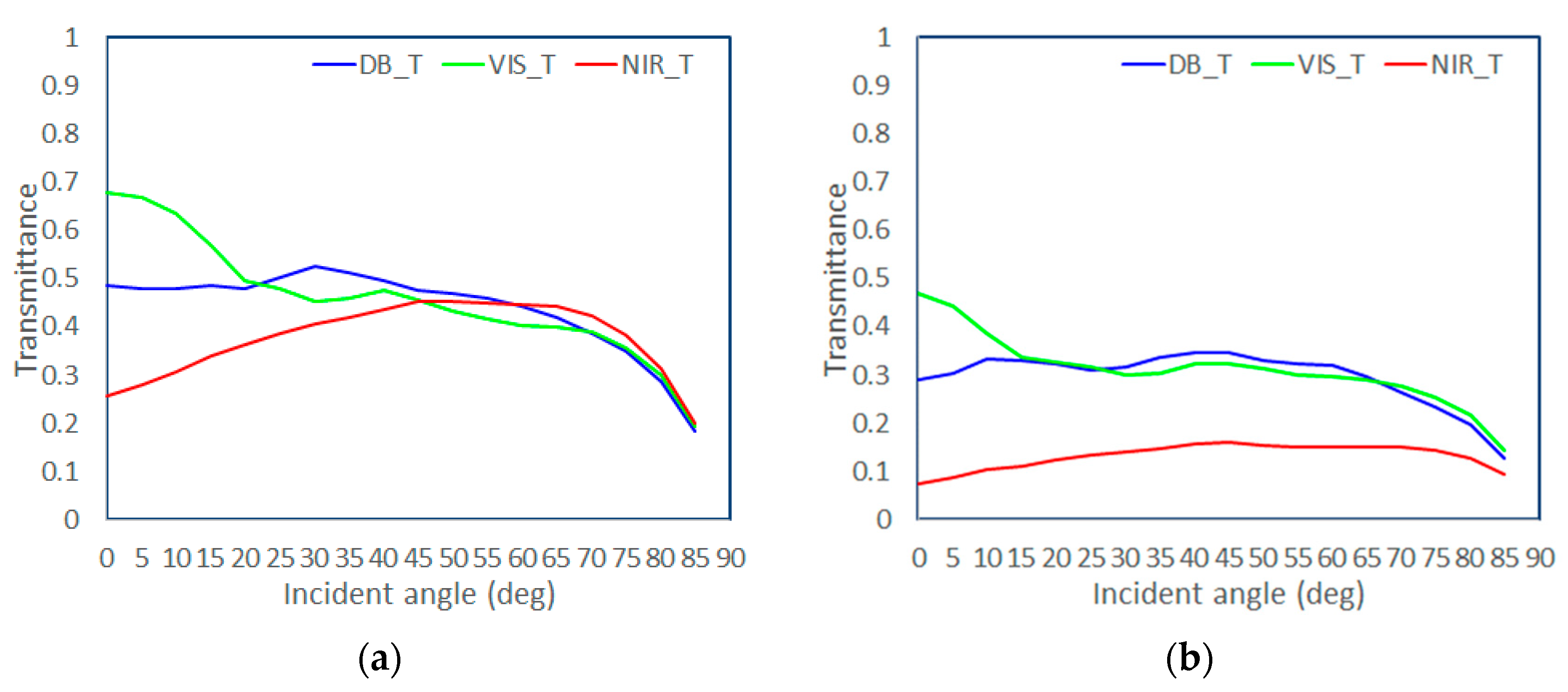
To more accurately evaluate the practical performance of the two designs under realistic conditions, we further simulated the relationship between incident angle and transmittance across the DB, VIS, and NIR spectral regions. The simulation results are presented in
Figure 8.
Figure 8a and
Figure 8b respectively illustrate the angular dependence of DB, VIS, and NIR transmittance for Design I and Design II. From
Figure 8a, it can be observed that Design I performs best at normal incidence (0°), showing the highest VIS transmittance, lowest NIR transmittance, and second-lowest DB transmittance. However, as the incident angle increases, VIS transmittance gradually decreases, while NIR transmittance increases and DB keeps stable. The difference between their transmittance values narrows with increasing angle. When the incident angle exceeds 25°, VIS transmittance falls below DB transmittance, and beyond 50°, the transmittance curves of all three bands become entangled and decline together. In contrast,
Figure 8b shows that Design II also achieves optimal performance at 0° incidence, with the highest VIS transmittance, the lowest NIR transmittance, and second-lowest DB transmittance. As the angle increases, VIS transmittance gradually decreases while DB keeps stable, reducing the spectral separation. A crossover occurs at approximately 25°, where VIS transmittance drops below DB. However, NIR transmittance in Design II remains relatively stable, ranging only from 0.12 to 0.2, and consistently stays lower than VIS transmittance across all incident angles.
When comparing both designs, Design I achieves the highest VIS transmittance at normal incidence (approximately 0.7), but its performance degrades sharply with increasing angle, dropping to about 0.3 at 85°, indicating high sensitivity to angular variation. Similarly, Design II starts at a lower VIS transmittance (approximately 0.53) and declines with incident angles. At normal incidence (0°), the DB transmittance of both Design I and Design II is lower than their respective VIS transmittance but higher than their respective NIR transmittance. This behavior arises because the DB region was not a primary optimization target; the optimization mainly focused on maximizing VIS transmittance and minimizing NIR transmittance, which are the performance indicators (VLT&SHGC) specified for green building glazing. The key difference lies in NIR transmittance: Design I shows a rise-and-fall trend with angle, fluctuating between 0.2 and 0.5, whereas Design II maintains a more stable range of 0.08–0.16, consistently lower across all angles. This confirms the superior NIR blocking performance of Design II. Therefore, under most practical application conditions, Design II is expected to deliver better thermal insulation, while Design I holds an advantage in maximizing VIS transmission. The simulation results demonstrate that the observed optical performance of both designs aligns well with their respective design goals. Nevertheless,
Figure 8 reveals an important observation: for both Design I and Design II, VIS transmittance drops noticeably when the incident angle exceeds 60°, implying that when used in building façade windows, both designs may show reduced VIS transmittance for direct sunlight at high solar elevations.

