Article

Development and Field Testing of a Suspended Mulberry Branch Harvesting and Stubble Cutting Machine

1
College of Mechanical and Electronic Engineering, Shandong Agricultural University, Tai’an 271018, China
2
Shandong Key Laboratory of Intelligent Production Technology and Equipment for Facility Horticulture, Tai’an 271018, China
3
Shandong Engineering Research Center of Agricultural Equipment Intelligentization, Tai’an 271018, China
4
Shandong Higher Education Institution Future Industry Engineering Research Center of Intelligent Agricultural Robots, Tai’an 271018, China
5
National Engineering Research Center of Agricultural Production Machinery and Equipment, Tai’an 271018, China
*
Author to whom correspondence should be addressed.
Appl. Sci. 2025, 15(2), 940; https://doi.org/10.3390/app15020940
Submission received: 20 December 2024 / Revised: 10 January 2025 / Accepted: 17 January 2025 / Published: 18 January 2025

Abstract

:
Stubble cutting is a critical step in the mechanized harvesting of mulberry trees. Poor stubble cutting quality can lead to root decay, and even the death of the trees, reducing the rate of rejuvenation. In view of the relatively high damage rate of stubble cutting in the mulberry harvesting operations, this paper has conducted in-depth research and designed a mulberry branch harvesting and stubble cutting test machine. The overall structure and key technical parameters of the machine were determined and the design of critical components was theoretically analyzed. Field tests identified an optimized set of cutting parameters that effectively reduced stubble damage and energy consumption. The optimal parameter combination included a saw blade line speed of 74 m/s, a star-wheel ground clearance of 727 mm, and a cutting speed ratio of 93, resulting in a cutting energy consumption within 1 m of 241 mJ and a stubble score of 8.5. These parameters met the quality standards for mulberry harvesting. This research provides valuable data support for analyzing and optimizing the cutting parameters of mulberry stubble-cutting machines, laying a solid foundation for advancing mechanized harvesting technology for mulberry trees.

1. Introduction

Mulberry trees, as perennial deciduous woody plants, exhibit significant nutritional value and economic potential [1,2]. Their leaves and tender branches are rich in high-quality protein, with crude protein content in dried mulberry leaf powder typically ranging from 25% to 40%, far surpassing many traditional forage resources [3,4,5]. This protein content adequately meets the basic dietary protein requirements of the sericulture industry, highlighting its economic importance [6,7,8]. Regional differences notably influence mulberry harvesting frequency and yield. In warm and humid southern regions, combined with livestock farming systems, mulberry trees can be harvested more than three times a year, with yields reaching up to four or five harvests, producing nearly 6 tons of fresh forage per acre annually [9,10]. By contrast, colder and drier northern climates limit harvesting frequency but still allow approximately three harvests per year.
Currently, silkworm rearing methods are divided into leaf-picking rearing and branch-cutting rearing. However, after harvesting, high-quality coppicing of mulberry trees is required to ensure the yield in the following year. Therefore, in order to achieve the sustainable utilization of mulberry trees, timely and scientific coppicing management is of crucial importance. Ideally, the coppicing cross-section should be smooth and round or oval to minimize the negative impact of adverse factors, such as rough edges, tearing, and burns, on the rejuvenation ability of mulberry branches. Specifically, an increase in the proportion of rough stubs will exacerbate water accumulation on the cross-section, which will then induce root rot and reduce the rejuvenation rate. Burns, on the other hand, will directly lead to the death of the stubble tissue and also weaken the rejuvenation ability [11,12,13,14,15,16,17,18]. Therefore, striving for high quality of the coppicing cross-section is essential for improving work efficiency and reducing costs. It is a key link in promoting the high-quality development of the modern sericulture industry. Hence, the research and development and application of mechanized low-damage coppicing technology are particularly important.
In the practice of harvesting forage crops, such as mulberry trees, traditional manual harvesting methods not only pose a risk of musculoskeletal injuries to operators but suffer from low efficiency. To reduce labor intensity and improve operational efficiency, the industry has actively developed various new harvesting tools in recent years, including electric handheld pruning shears and semi-automatic pruners [19,20,21]. However, these small-scale stubble-cutting devices are primarily suitable for shrubs with smaller diameters due to their lightweight, compact structure, operational flexibility, and high safety features. Nevertheless, prolonged use of such equipment increases physical fatigue and makes it challenging to maintain uniform cutting height and control stubble splitting, thereby affecting harvesting quality.
Currently, the development of mechanized mulberry harvesting technology remains in its early stages, prompting the industry to focus on the research of stem-cutting test benches to drive progress. Deng Linglei et al. [22] designed a disc-type corn stalk cutting test bench and used high-speed photography and motion analysis devices to explore the three characteristic stages of the stalk-cutting process. Shen Cheng et al. [23] developed a hemp stalk harvesting bench, applying a multi-factor orthogonal experiment to determine the optimal combination of blade length, blade edge type, and the number of active blades based on different test factors. Lu Yong [24] and his team developed a single-disc sugarcane cutter test bench and established detailed sugarcane cutting state criteria. Through physical experiments, they determined judgment criteria for cutting head crushing and used kinematic simulation technology to identify that a configuration with low frequency, low speed ratio, small amplitude, and fewer blades effectively reduces cutting head breakage.
Additionally, Gao et al. [25] designed a Caragana korshinskii branch sawing test bench and conducted a series of sawing experiments to investigate the relationships between branch diameter, average cutting speed, wedge angle, sliding cutting angle, cutting height, cutting gap, moisture content, and peak cutting force, ultimately determining the optimal cutting parameter combination. Zhang et al. [26] developed a stalk-cutting test bench and designed a measurement and control system based on the LabVIEW platform. This system not only simulates diverse cutting conditions but precisely measures and analyzes cutting force and cutting speed data. Zhao et al. [27] created a high-stubble corn stalk cutting test bench, conducting in-depth studies on the effects of working parameters on maximum cutting force and energy consumption. They derived the optimal parameter combination for achieving the best corn stalk cutting performance under a single-side fixed and unsupported cutting condition.
Currently, research activities are primarily focused on the design exploration and experimental verification of cutting test benches [28,29,30]. However, the key issue of how specific machine operation parameters affect cutting quality still requires further investigation. This limitation partially restricts the potential for improving the harvesting quality of mulberry trees. In response to the high rate of cutting damage during mulberry harvesting, this study designs a mulberry cutting experiment machine with a flat cutting mechanism. The overall structural layout and main technical parameters are defined, and the design concepts for key components are analyzed in detail. Through a series of field tests, this research provides an optimized cutting operation parameter plan, which helps reduce cutting damage rates and save energy consumption, offering valuable reference information for improving mulberry tree mechanized harvesting technology.

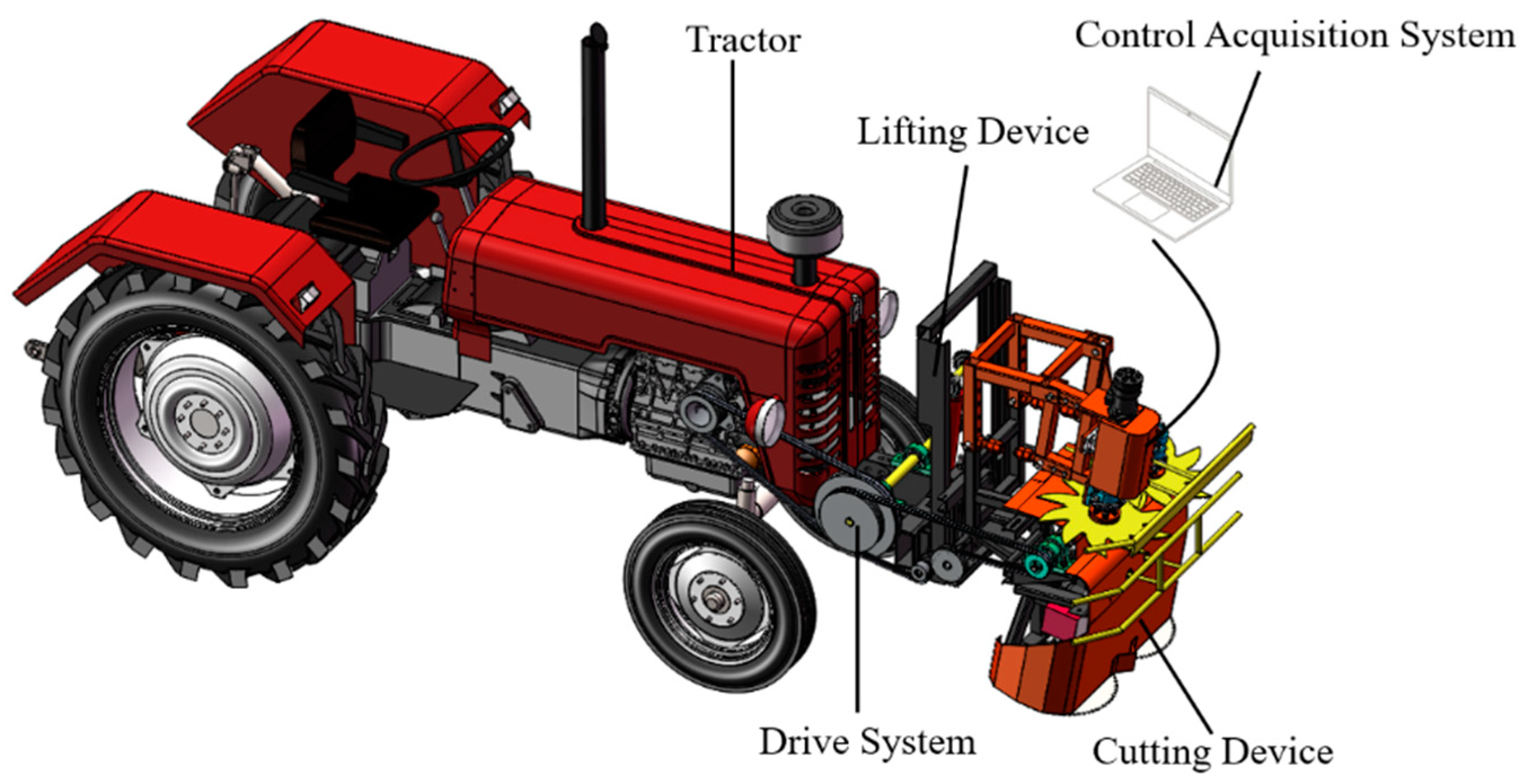
2. Mechanical Structure and Working Principles

2.1. Mechanical Structure

Based on the growth characteristics of mulberry trees and the agronomic requirements for flat cutting during mulberry harvesting, a mulberry branch cutting experimental machine has been developed. The whole machine model in SolidWorks is shown in Figure 1. This experimental machine primarily consists of a cutting platform, hydraulic control system, signal acquisition system, and main machine. The cutting platform is mainly composed of a grain separation star wheel, a crop guiding rod, a circular saw-type cutter, a cutting platform lifting device, and a frame. The circular saw-type cutter is driven by a belt transmission, while the grain separation device is driven by a chain transmission. The signal acquisition system mainly includes a torque sensor, transmitter, and acquisition computer. The cutting platform is connected to the main machine frame through the cutting platform lifting device. The main machine consists of an internal combustion engine, clutch, gearbox, hand throttle, and chassis. The forward speed of the experimental machine is controlled by adjusting the internal combustion engine throttle and changing the gearbox’s gear settings. The rotational speeds of the circular saw-type cutter and grain separation star wheel are adjusted by varying the internal combustion engine throttle. This experimental machine is capable of simultaneously performing three tasks: mulberry branch cutting, flat cutting of mulberry trees after harvesting, and laying out the mulberry branches.
During operation, torque sensors installed on the power drive shaft of the cutter and the drive shaft of the grain separation star wheel measure the input torque and rotational speed of both the circular saw-type cutter drive shaft and the grain separation star wheel drive shaft.

2.2. Working Principles

Before starting the flat cutting operation, the lifting device is adjusted according to the required cutting height for the mulberry orchard. This ensures that the circular saw blade is at the correct height to meet the flat cutting requirements for the mulberry trees. At the same time, the belt tensioning device automatically adjusts the belt’s tension to ensure proper power transmission and prevent slippage during operation.
The power for the cutting device comes from the tractor’s flywheel, which drives two V-type transition pulleys through a V-belt. This increases the speed of the cutting platform, allowing the circular saw spindle to reach the necessary working speed. The grain separation device receives power through the tractor’s rear output shaft, which sends it to a gearbox that increases speed. This gearbox is connected to a hydraulic motor, which transmits power through the hydraulic system to the pump on the grain separation star wheel spindle. The speed of the star wheel is controlled by adjusting a flow valve.
The grain separation star wheel rotates in the same direction within the working plane. It works with the guiding rod to move the mulberry branches, which have been flat-cut, to the right side of the machine’s forward direction, ensuring they are laid down evenly. This makes it easier to collect and transport the branches later.

2.3. Main Technical Parameters

By referring to the Agricultural Machinery Design Handbook [31], and considering actual production and manufacturing conditions, while also taking into account the requirements of the harvesting conditions and the actual field situations, the main technical parameters of the mulberry branch cutting flat cutting experimental machine have been determined. These parameters are shown in Table 1:

3. Key Component Design
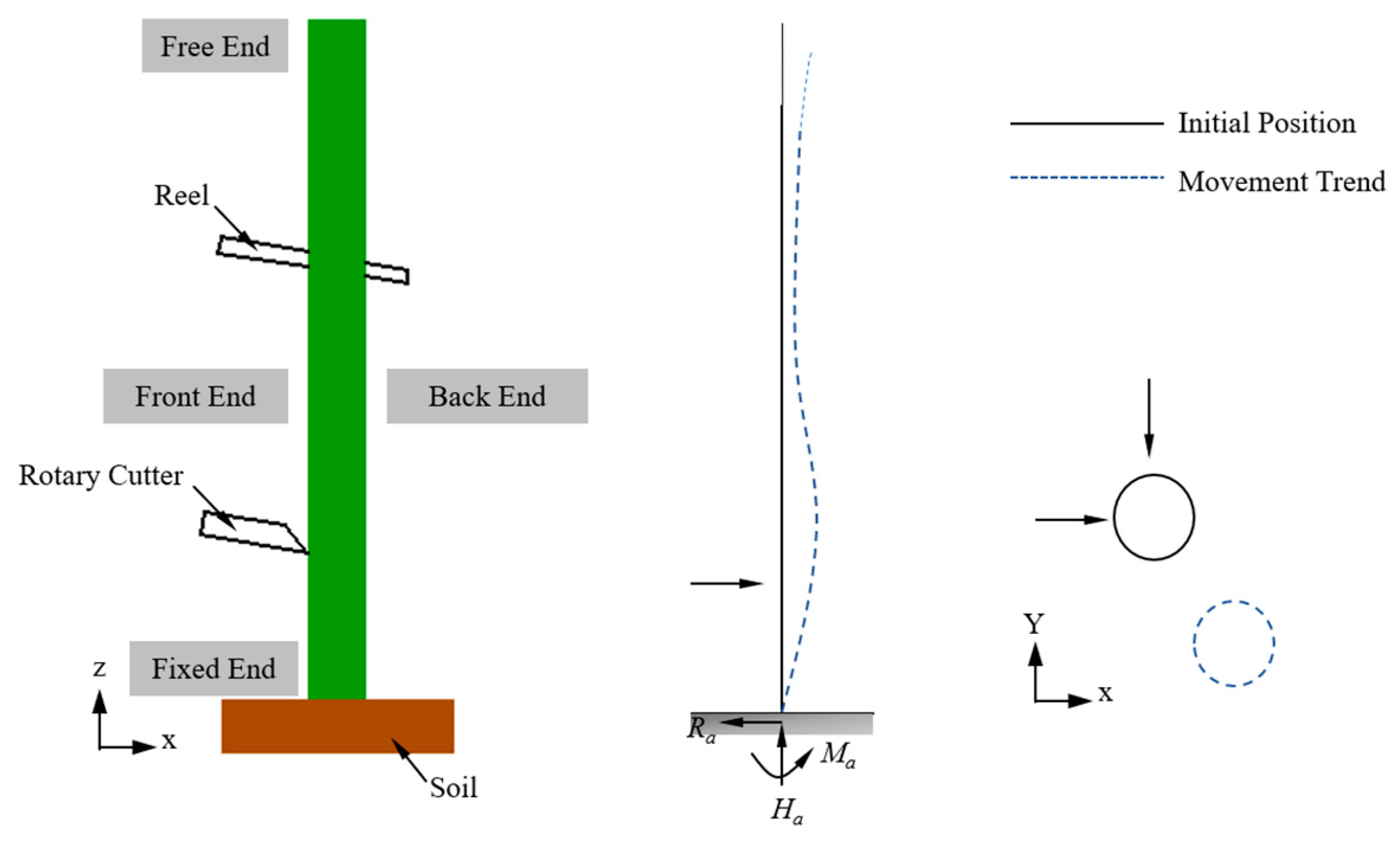
3.1. Cutter Design

The cutting platform of the mulberry branch cutting experimental machine is a vertical cutting platform, mainly composed of a grain separation star wheel, crop guiding rod, circular saw-type cutter, sensors, and frame, as shown in Figure 2.

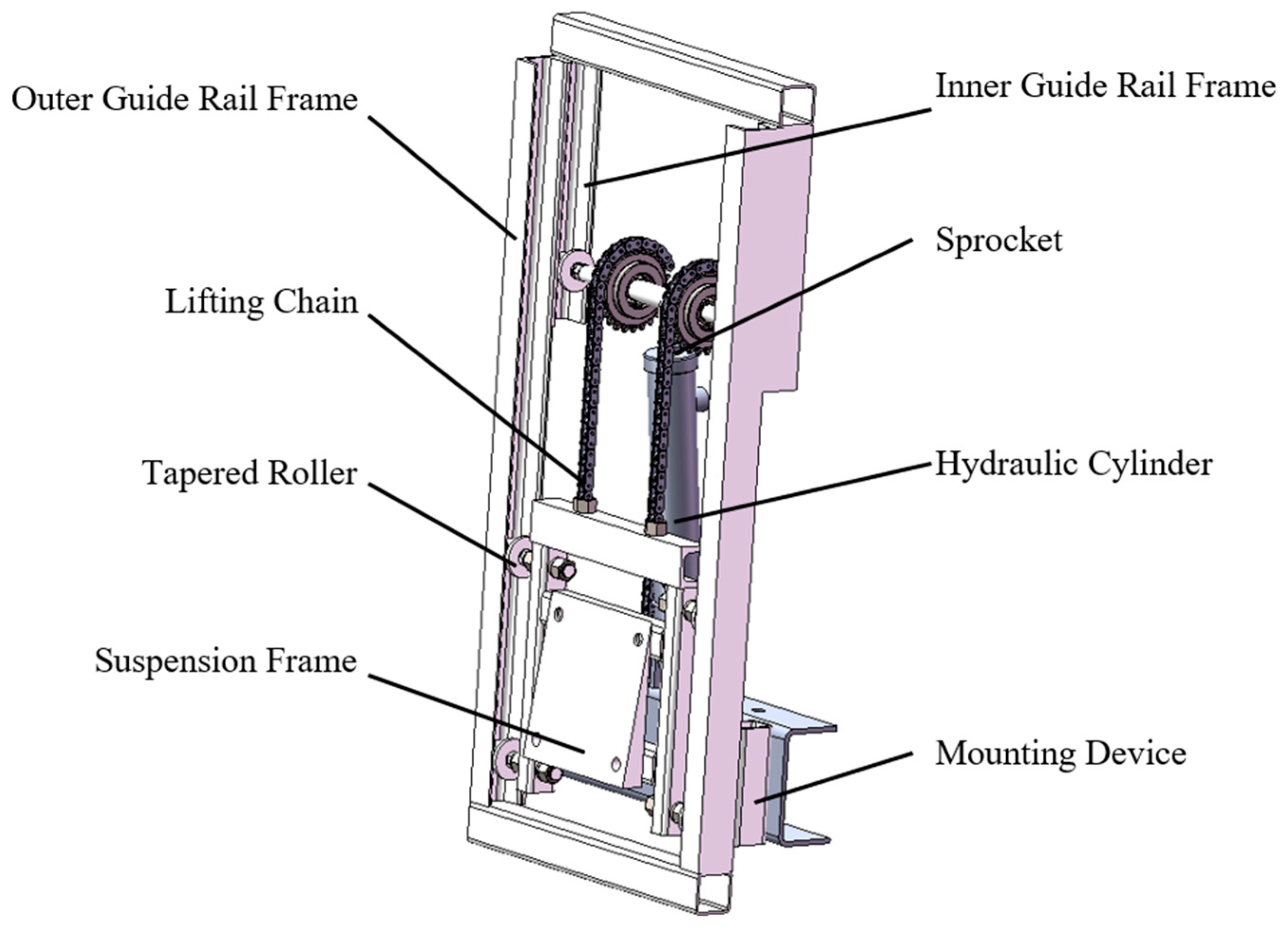
3.1.1. Lifting Apparatus Design

To ensure safe and reliable adjustment of the cutting height while adapting to terrain changes, a lifting device was designed for the cutting platform. The device includes key components, such as a hydraulic cylinder, lifting chains, tapered rollers, and an inner–outer guide rail frame, as shown in Figure 3.
The inner–outer guide rail frame is constructed from parallel-welded channel steel, serving both as a planar support structure and as a stable moving track for the suspension frame and hydraulic cylinder. This structure is crucial for the lifting system’s operation.
Tapered rollers at both ends of the suspension frame slide along the outer and inner guide rails, respectively. The roller connected to the hydraulic cylinder moves along the inner guide rail, working in coordination to adjust the cutting platform height. One end of the lifting chain is attached to the top of the suspension frame, while the other end is fixed to the inner guide rail crossbeam. Adjustment bolts and nuts ensure the two chains remain equal in length, achieving balanced loading.
The sprocket, sharing a coaxial point with the hydraulic cylinder’s pivot, moves in a straight line under the guidance of the inner guide rail frame and tapered rollers, functioning as a movable pulley. The cutting platform is suspended from the outer guide rail frame by tapered rollers, driven by the hydraulic cylinder, and lifted vertically along the outer guide rail by the lifting chain.
During operation, the hydraulic cylinder precisely controls the cutting platform’s vertical movement. A four-point positioning mechanism ensures the platform remains upright throughout the lifting process, effectively preventing uneven cuts caused by angle deviations and supporting the healthy regrowth of mulberry branches.

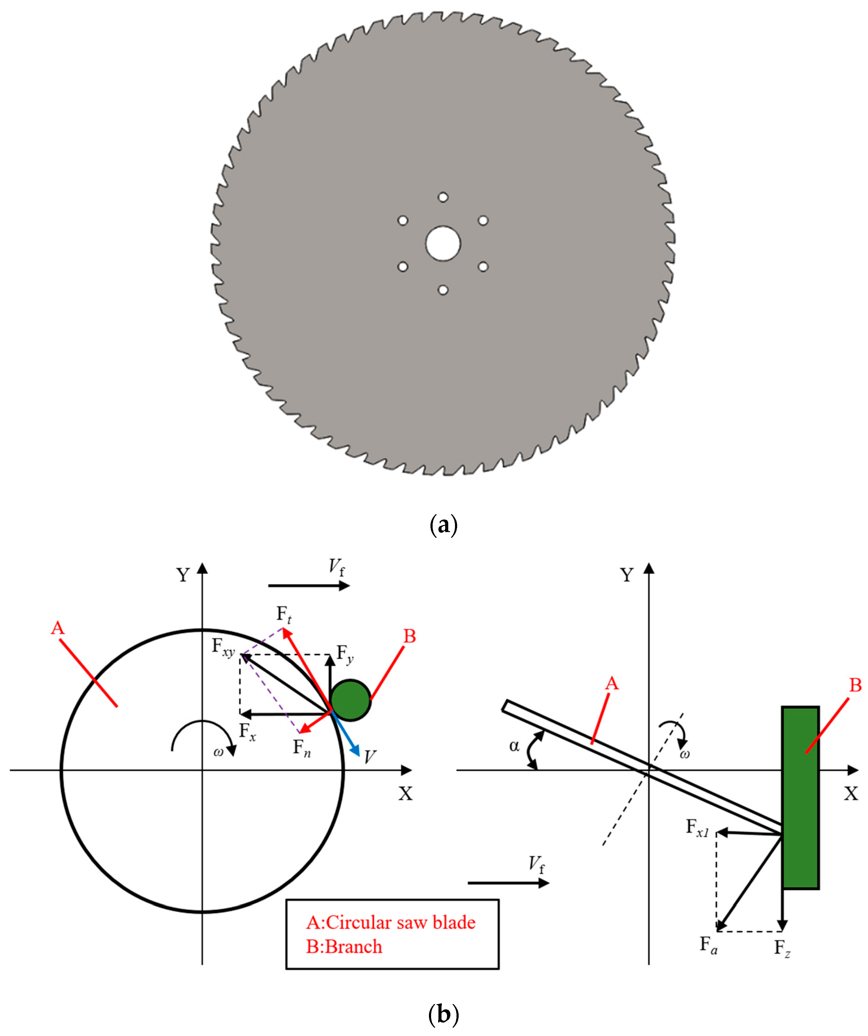
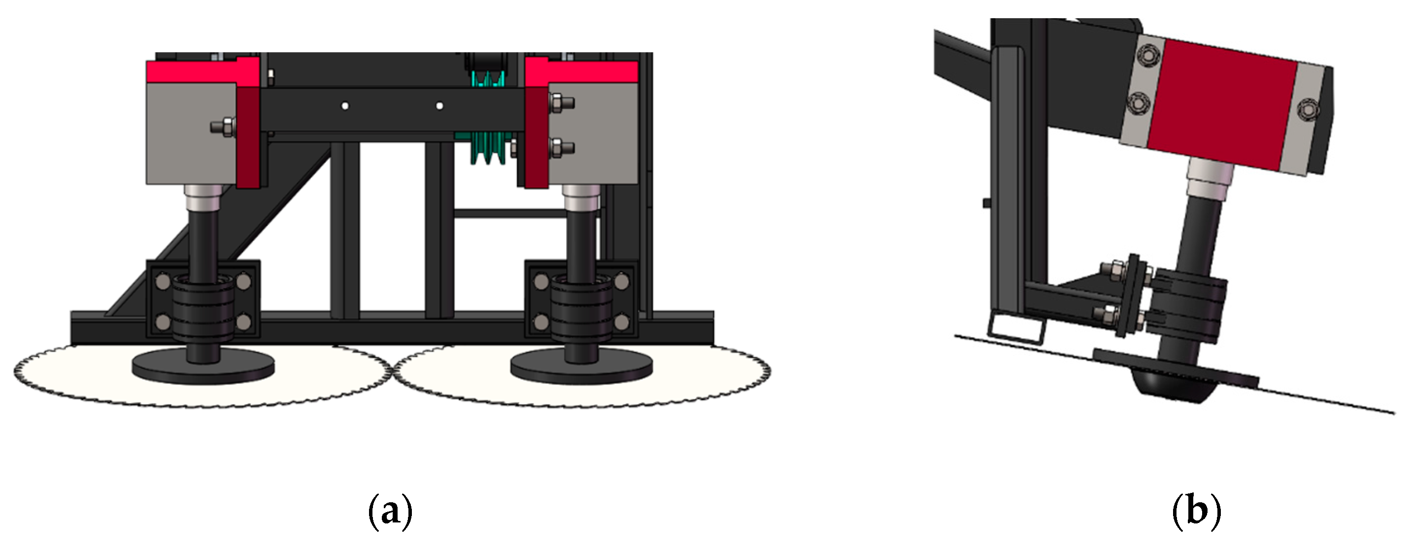
3.1.2. Design of the Circular Saw-Type Cutter

A customized circular saw cutter with material-feeding teeth was designed specifically for cross-cutting hardwood, as shown in Figure 4a. The cutter features a 400 mm outer diameter, 96 teeth, and a −5° rake angle to enhance cutting power and wear resistance, ensuring smooth and precise cutting. The blade thickness is 4 mm, with a 30 mm central bore. Six evenly distributed Φ5 mm mounting holes on a 166 mm-diameter circle provide stable and efficient cutting operation.
As shown in Figure 4b, the circular saw blade is generally subject to the influences of axial force, tangential force and radial force. Among them, ω represents the cutting rotational speed, Vf denotes the feed speed, α is the cutting inclination angle of the circular saw blade, and V represents the cutting linear velocity of the circular saw teeth. The cutting force F can be decomposed into radial force Fn, tangential force Ft and axial force Fa. The radial force Fn is mainly generated due to the impact of branches on the circular saw blade during cutting and the reaction force caused by the bending deformation of branches on the circular saw blade. The tangential force Ft is mainly produced by the reaction force of the friction when the circular saw blade cuts branches. This force is parallel to V but in the opposite direction, as it is opposite to the direction of the cutting rotational speed. The axial force Fa is mainly caused by the machining errors and installation errors of the circular saw blade, as well as the extrusion and collision of oblique branches on the circular saw blade, and its corresponding direction is along the installation axis of the circular saw blade and perpendicular to the surface of the circular saw blade. To simplify the calculation, the resultant force Fxy of the radial force Fn and the tangential force Ft can be equivalently decomposed into a horizontal force Fx in the feed direction in the XY plane and a force Fy perpendicular to Fx in the XY plane for measurement and analysis. The axial force Fa can be equivalent to a vertical downward force Fz and a horizontal force Fx1. The resulting cutting force F can be expressed by Equation (1):
F = F a × cos α + F a × sin α 2 + F n 2 + F t 2
In the saw cutting device, as shown in Figure 5, two circular saw blades are symmetrically mounted at the front end with a 390 mm spacing between the rotating shafts, and a 5 mm gap between the saw blades to optimize cutting. The top of the spindle integrates a 6−15 × 20 × 3 splined shaft sleeve, which fits seamlessly with the Yongbo 150 reversing splined shaft, ensuring transmission accuracy and stability. The spindle is supported by a 32,006 type tapered roller bearing, with a 20 mm circular ring spacer between the bearings, effectively dispersing axial loads and preventing blade movement. Special washers are added above and below the saw blades to expand the contact area, reduce vibration, and minimize the risk of vertical vibrations and collision damage. The bolts beneath the spindle use left-hand threads to reduce the risk of loosening and enhance operational safety.

3.1.3. Design of the Grain Separation Device

During the process of agricultural machinery harvesting, the main function of the grain separation star wheel is to lift up the crops and guide them towards the cutting device. According to the Agricultural Machinery Design Handbook, the necessary condition for the normal operation of the grain separation star wheel is that the speed ratio (the ratio of the line speed of the separation wheel to the machine’s forward speed) must be greater than 1. When the speed ratio is less than or equal to 1, the linear velocity of the grain separation star wheel is less than or equal to the forward speed of the machine. This means that the grain separation star wheel cannot effectively guide the crops backward, and the crops may tip forward or fail to be guided to the cutting device in a timely manner. Increasing the speed ratio can expand the working range of the star wheel and improve its effectiveness. However, under constant machine forward speed, excessively increasing the line speed of the star wheel may damage the mulberry branches. Based on practical experience, the recommended line speed of the separator blade should not exceed 3 m/s.
The condition for the grain separation star wheel to achieve single-plant feeding is to ensure that only one mulberry tree is present between two adjacent star wheel teeth during forward harvesting. When a single feed finger of the star wheel completes one full rotation and accurately feeds a single mulberry tree, a continuous single plant feeding process is formed. As shown in Figure 6, the first mulberry tree is at point a. After being grabbed and longitudinally output by feed finger 1, the machine moves to position Sab, at which point the second mulberry tree moves from point b to point a. If feed finger 2 reaches point a in time or exactly at the right moment, it ensures that only one mulberry tree is fed per rotation of the finger. This process can be expressed by Equation (2) [31]:
N b 6 v S a b
where Sab is the plant spacing of mulberry trees (m), with Sab = 1 m taken, v is the tractor forward speed (m/s), with v = 2 m/s taken, and Nb is the rotational speed of the star wheel (r/min).
It is calculated that: Nb ≥ 60 r/min, that is, the linear velocity of the star wheel is v ≥ 1.44 m/s.
As shown in Figure 7, the grain separation device consists of a fixed frame and a movable frame. The fixed frame is welded to the cutting platform, while the movable frame is connected to the fixed frame by bolts, allowing for easy adjustment of the separation height and the longitudinal spacing between the separation star wheel and the saw blade in contact with the mulberry branches. The left-side separation star wheel is equipped with a hydraulic motor and bolted to the movable frame, with a torque sensor installed to monitor and output torque signals. The device uses a pair of external spherical vertical bearing housings (bolted to the movable frame) to provide stable support. A drive sprocket is located between the separation star disc and the spindle bearing housing, transmitting power to the other star disc via a chain. During operation, the separation star wheel rotates clockwise, conveying the mulberry branches to the right side in the direction of the machine’s forward movement. The design of the upper guide rod is intended to prevent the branches from continuing to rotate with the star wheel if they have not been successfully separated, thus avoiding blockages. The hydraulic motor provides power and ensures that the separation star wheel operates smoothly at different speeds through chain transmission, effectively preventing mulberry branch blockages.
The displacement of the mulberry branches under the action of the grain separation device is illustrated in Figure 8. Based on the principles of material mechanics, since one end of the mulberry branch is fixed in the soil and its deformation is mainly bending deformation, the mulberry branch is modeled as a simplified cantilever beam. Under the radial external load, the mulberry branch undergoes bending deformation. During the cutting process, the possible movement trend of the mulberry branch is shown in Figure 8, where Ra, Ha, and Ma represent the reaction forces exerted by the soil on the mulberry branch. Under the combined action of the blade and the separation star wheel, the mulberry branch experiences both stretching and bending deformation, specifically with the front end being stretched and the rear end being compressed. As the separation star wheel moves and the base cutter rotates, the mulberry branch displaces along the Y direction. Simultaneously, due to the forward motion of the test machine, the mulberry branch also displaces along the X direction, as shown in Figure 8.
During the cutting process, the cutting force fluctuates significantly over time, leading to dynamic changes in the mulberry branch’s motion state. Specifically, the root of the mulberry branch remains fixed; the part near the cutting position displaces along the X direction due to the action of the separation force, while the part near the separation position experiences a more significant displacement due to the effect of the separation force and, as it is close to the cutting area, the displacement amplitude continues to increase. The free end of the mulberry branch, under the combined action of multiple forces, also experiences an increasing displacement amplitude. Overall, the mulberry branch exhibits a tendency to move in the X direction. At the same time, the Y-direction displacement of the root remains zero; the part near the cutting position moves in the -Y direction, and the mulberry branch near the separation position and free end also moves in the -Y direction. This support cutting method ensures that the movement direction of the cut part of the mulberry branch is consistent with the top free end’s direction, effectively reducing potential damage caused by irregular movements.

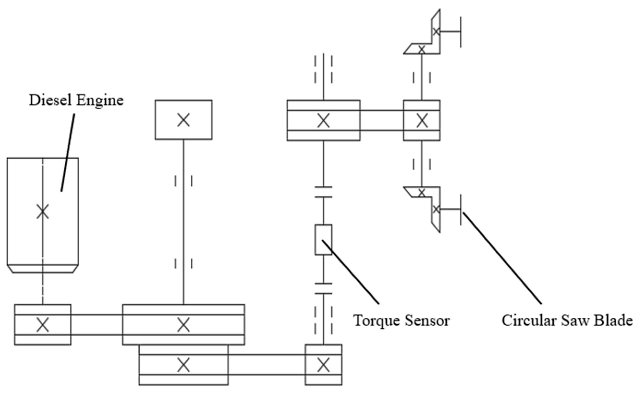
3.2. Transmission System Design

When selecting a 400 mm diameter circular saw blade, the rotational speed of the spindle for the saw blade is calculated using the formula shown in Equation (3). According to the design plan, the linear speed of the circular saw is 90 m/s:
V = π d 1 n 60 × 1000
where V is the linear speed of the circular saw (m/s), d1 is the diameter of the circular saw blade (mm), and n is the rotational speed of the spindle of the circular saw blade (r/min).
Through calculations, the minimum spindle speed of the circular saw required to achieve the desired linear speed of the saw blade is 4297 r/min.
Figure 9 shows the V-belt transmission system of the cutting device: V-belt pulleys 1 to 6 have different diameters and are driven by the tractor TS250 (2200 r/min). The speed is first reduced by a single-stage reduction (2.20 times) to 1000 r/min, then increased through two stages of speed increase (2.57 times and 2.09 times) to 5371 r/min. Finally, the speed is reduced by a gear reducer and a 1.25-fold reduction, resulting in a theoretical spindle speed of 4297 r/min and a linear speed of 90 m/s for the saw blade.
The feeding device utilizes the power provided by the tractor’s rear output shaft. It connects the rear output shaft to the matching gearbox, which is externally connected to a hydraulic pump. Through hydraulic piping, the hydraulic pump and hydraulic motor are connected, and the spindle of the hydraulic motor is linked to the spindle of the feeding star wheel, thereby enabling the rotational movement of the feeding star wheel and achieving the feeding function. The design plan specifies the rotational speed of the feeding star wheel to be 145 r/min. The corresponding hydraulic pump and hydraulic motor are selected based on the calculation from Equation (4):
n m = q m 1000 × n p × η v m × η m m V m
where nm is the rotational speed of the hydraulic motor (r/min), qm is the flow rate of the hydraulic pump (mL/r), np is the rotational speed of the hydraulic pump (r/min), ηvm is the volumetric efficiency of the hydraulic motor (%), ηmm is the mechanical efficiency of the hydraulic motor (mm), and Vm is the displacement of the hydraulic motor (mL/r).
Based on the calculations, the BM1-100 four-hole shaft 25 hydraulic motor and the KGP2E2D16Z5F9 hydraulic pump were selected, which are capable of adjusting the rotational speed of the feeding star wheel between 0 and 145 r/min.

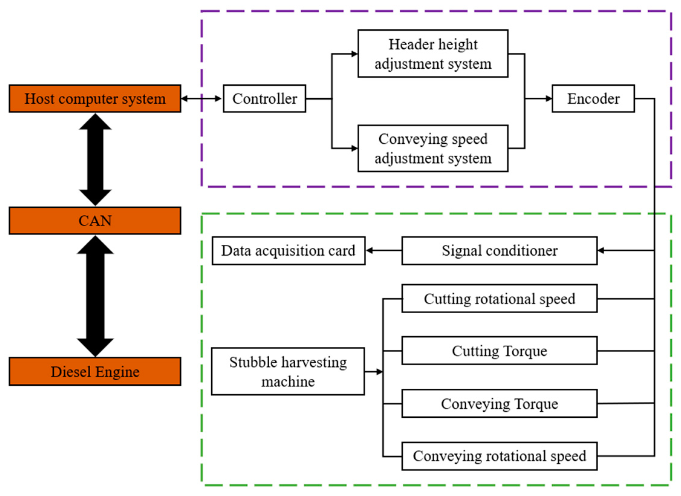
3.3. Control and Acquisition System Design

The hardware of the upper computer control and acquisition system for the test machine mainly includes a signal conditioner, data acquisition card, hydraulic control encoder, and hydraulic controller, which are divided into the leveling machine data acquisition system and hydraulic control system. By using torque sensors installed on the drive shaft of the cutting device and the main shaft of the feeding device, the system can acquire torque, speed, and power during the cutting and feeding processes. The encoders are used to control the hydraulic systems of the lifting device and feeding device, thereby controlling the lifting height and feeding speed. The schematic diagram of the system hardware is shown in Figure 10.

4. Prototype Field Test

4.1. Cutting Quality Evaluation Standards

Based on the evaluation system for the cutting quality of Caragana korshinskii (a type of branch) and sugarcane, as well as the agronomic standards for mulberry harvesting and leveling [11,12,13,14,15,16,17,18], this paper proposes a quality evaluation standard applicable to mulberry tree harvesting and leveling. The evaluation system for Caragana korshinskii includes indicators, such as cutting height, pore area ratio, wound height, the number of stepped wounds, crack length, stepped wound depth, crack depth, and scorch area ratio. However, an empirical analysis shows that wound height, crack length, number of stepped wounds, crack depth, and stepped wound depth have minimal impact on the regeneration ability of Caragana korshinskii. Therefore, these factors can be excluded from the mulberry cutting and leveling evaluation. Combining the practical experience of mulberry farmers and the cutting quality evaluation indicators, this study identifies wound condition and splitting degree as the key evaluation criteria for mulberry cutting and leveling.
The formula for calculating the damage degree for a single mulberry branch is as follows in Equation (5) [32]:
D = S m x m + S p x p
where D is the damage degree of a single mulberry branch, Sm is the ratio of the area of the rough stub of the mulberry branch to the maximum diameter of the mulberry branch (mm), xm is the weight of the area of the mulberry branch rough stub occupied (mm−1), with a value of 0.5 taken, Sp is the ratio of the area of phloem tearing damage of the mulberry branch to the maximum diameter of the mulberry branch (mm), and xp is the weight occupied by the area of phloem tearing damage of the mulberry branch (mm), with a value of 0.5 taken.
The quantification standard for the cutting damage degree based on the damage degree of a single mulberry branch is mainly divided into two parts: damage to lateral buds and no damage to lateral buds.
  • No damage to lateral buds (no occurrence of xylem splitting or phloem tearing) and the damage degree of a single mulberry branch within 5% is rated 10 points.
  • The damage degree of a single mulberry branch within 5–10% is rated 9 points.
  • The damage degree of a single mulberry branch within 11–15% is rated 8 points.
  • The damage degree of a single mulberry branch within 16–20% is rated 7 points.
  • The damage degree of a single mulberry branch within 21–30% is rated 6 points.
  • Damage to lateral buds (occurrence of xylem splitting and phloem tearing) is rated 0 points, indicating severe damage.
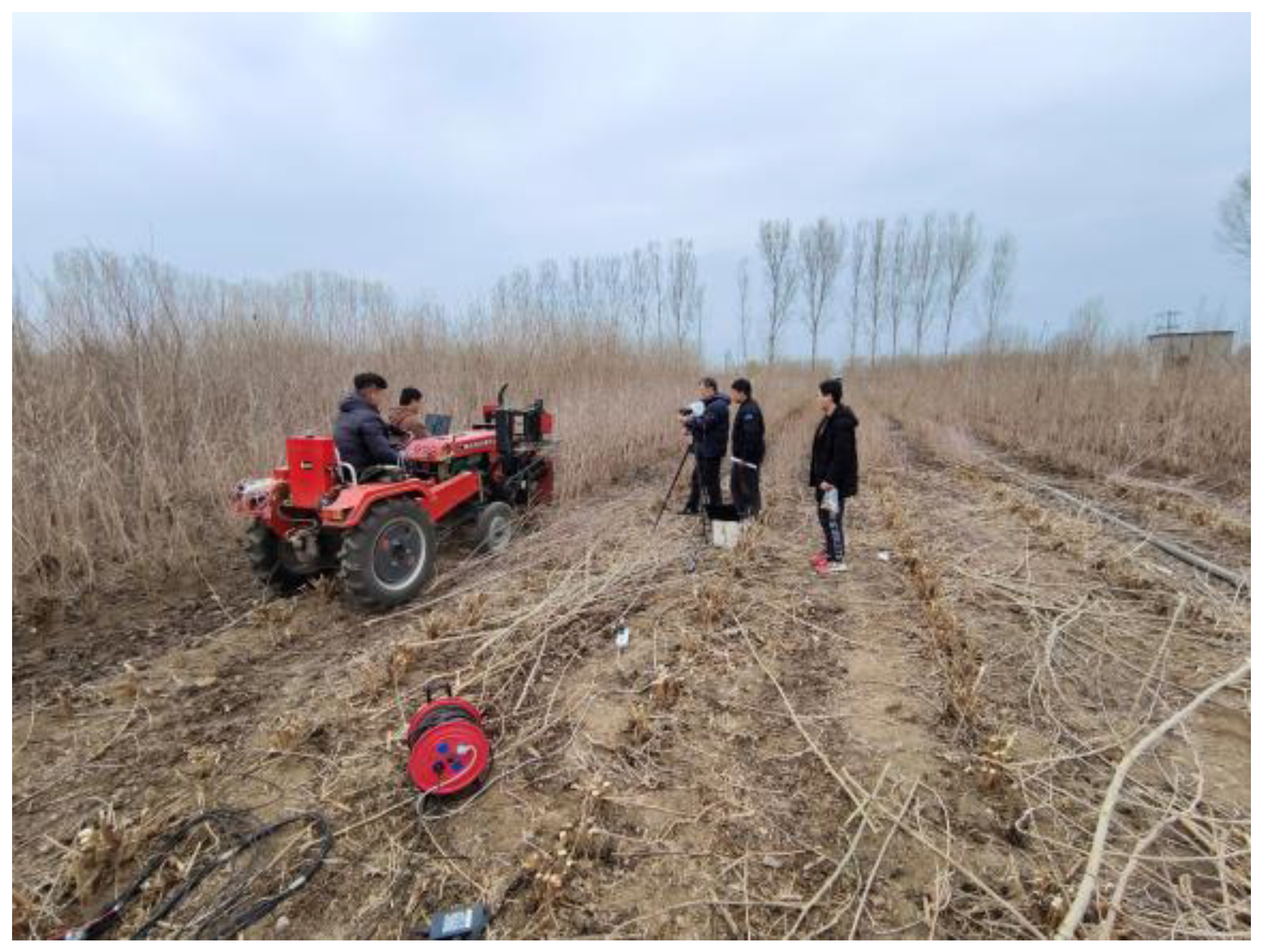
The scoring reference is shown in Figure 11.

4.2. Field Test

The field test was conducted on 14 March 2023, at the mulberry planting base of Tai’an Bafu Agricultural Technology Co., Ltd. located in Dazhao Village, Xiangyin Town, Ningyang County, Tai’an City (35°43′ N 116°52′ E). The mulberry variety used in the test was Guiyou No. 62. The purpose of the test was to verify whether the cutting platform met the design requirements to complete the cutting and leveling work, and to assess the stability and reliability of data collection. The orthogonal experiment was conducted to obtain the optimal combination of harvesting parameters for the feeding wheel and cutter. Under the optimal cutting parameter combination, the best feeding and conveying state and the highest cutting quality were validated.

4.2.1. Test Methodology

The cutting height was set to 10 cm. To reduce the impact of random errors, each test was repeated three times. The current status of the test is shown in Figure 12.
After completing the prototype debugging and preliminary preparations, the operator drove the tractor into the mulberry orchard for field testing. Before each cutting operation, the tractor needed to drive at least 5 m in advance. Meanwhile, the torque measurement system continuously recorded the data from the torque sensors, including torque and rotational speed. After completing the cutting, the conditions of all stumps were recorded in detail, and a 1-m length sample was selected for analysis.
This study focuses on the cutting quality and the torque signals during the cutting process. It implements single factor experiments on disc saw line speed, cutting speed ratio (the ratio of cutting speed to forward speed), and the height of the mulberry cutting blade from the ground, and optimizes using a central composite design (CCD), eliminating factors with insignificant influence. The experimental settings are shown in Table 2 and Table 3. Table 2 is a single-factor experiment. When conducting OFAT experiments on each factor at five levels, respectively, the assumed values of the other two factors are set as the intermediate values of their levels. Table 3 is a CCD experiment, in which real factors are adopted for the design. It can effectively find the optimal combination of working parameters, thus realizing the optimization of working parameters. Meanwhile, while taking into account the interaction among various working parameters, it can also reduce the number of trials. Each test was repeated three times to ensure data reliability. Evaluation metrics include the condition of the stumps after cutting. After the tests, stump samples from designated locations were collected, and the prototype was thoroughly checked to confirm its operational status.

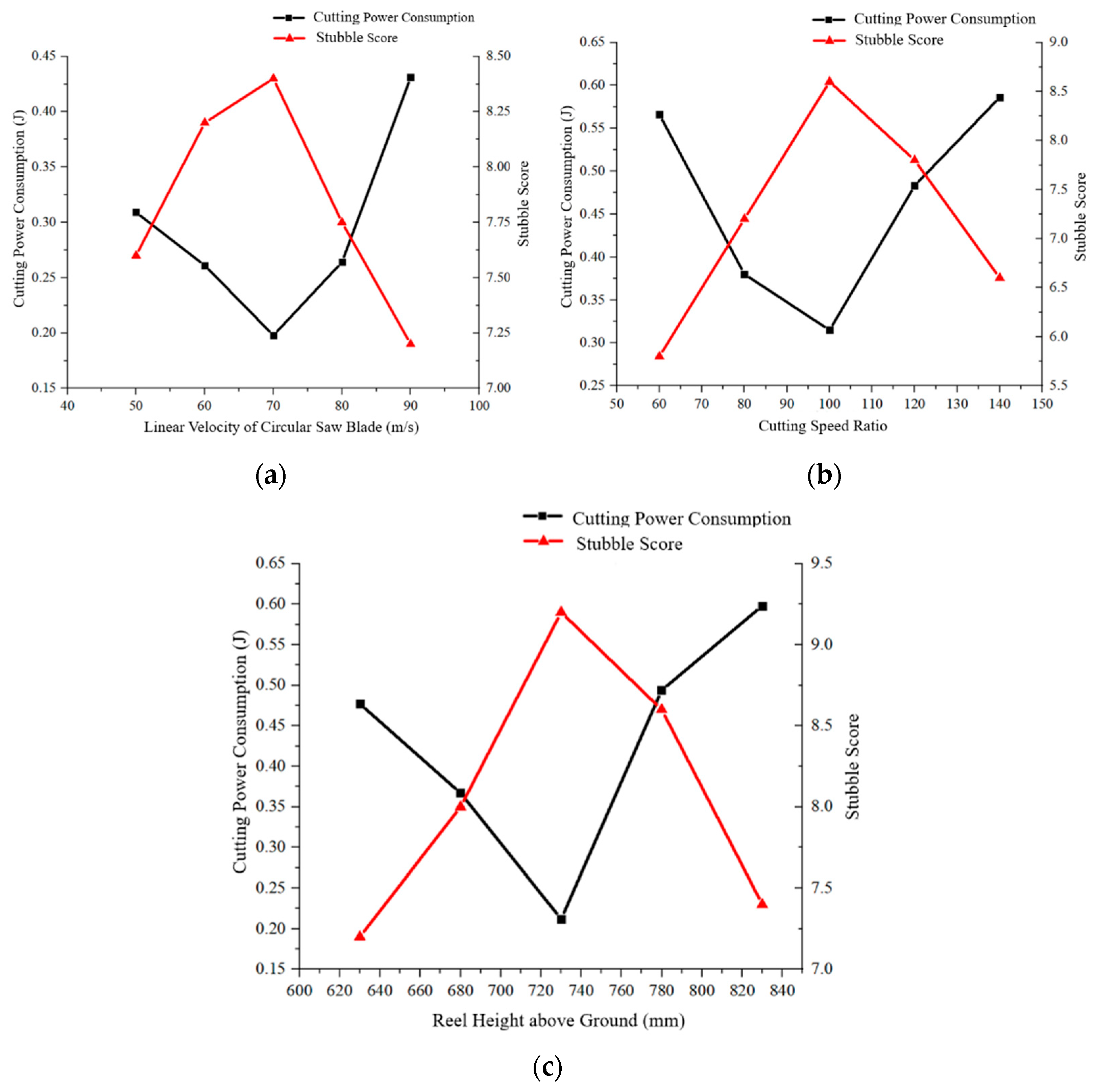
4.2.2. Single-Factor Experiment Results and Analysis

In the operation of the disc saw, the primary forces acting on it are radial force and tangential force, with the axial force fluctuations being relatively small. Specifically, the tangential force arises from the resistance encountered by the saw teeth when cutting the material, while the radial force is mainly generated by the impact forces during the cutting process. The axial force primarily originates from the pressure applied during the cutting operation and the effect of the mulberry stripping operation.
Through a detailed analysis of Figure 13a, it can be observed that, when the cutting speed is in a lower range, the feed rate per tooth is relatively large, which leads to a significant increase in frictional resistance. In this situation, the energy consumption gradually decreases as the cutting speed increases. However, when the cutting speed becomes too high, the disc saw tends to experience vibration, significantly reducing its operational stability and causing an increase in energy consumption. It is worth noting that a moderate increase in the cutting speed has a positive effect on improving the cutting quality. However, as the cutting speed continues to increase, it leads to corresponding increases in feed speed and mulberry stripping speed, ultimately resulting in a decline in cutting quality. Experimental studies have shown that when the disc saw’s line speed reaches 70 m/s, the cutting energy consumption achieves its lowest point, while the cutting quality reaches its highest level. At this point, the cutting performance is optimal.
Further observation, as shown in Figure 13b, reveals that, as the cutting speed ratio increases, the feed rate continues to decrease, while the energy consumption initially decreases and then increases. Although an increase in the cutting speed ratio leads to a decline in cutting quality, a moderate increase in feed rate under lower feed speed conditions helps to improve the mulberry stripping effect. Repeated experiments confirm that when the cutting speed ratio is set to 100, the energy consumption is minimized, and the cutting quality reaches its best level.
From Figure 13c, it can be seen that, under the action of the mulberry stripping star wheel, the cutting energy consumption initially decreases and then increases, while the cutting quality score first rises and then falls. When the height of the mulberry stripping star wheel from the ground is adjusted to 730 mm, the best cutting effect is achieved.
In summary, by precisely adjusting the relevant parameters to specific values, the dual optimization goals of minimizing cutting energy consumption and maximizing cutting quality can be achieved for the disc saw.

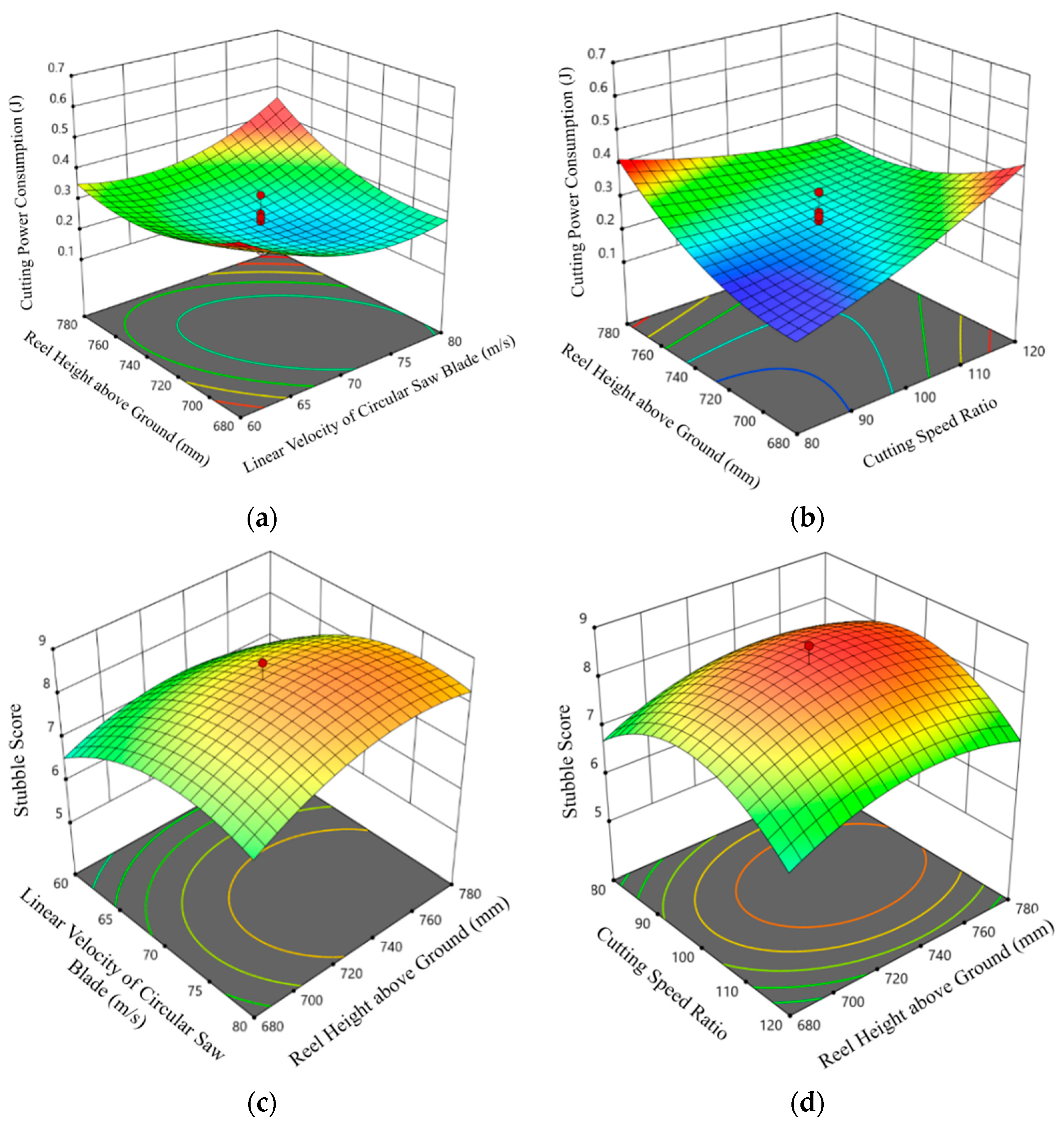
4.2.3. Central Composite Experiment Results and Analysis

The results of the central composite experiment are shown in Table 4.
Based on the experimental data in Table 4, the mathematical models for the cutting energy consumption and stubble score of the mulberry branches, using the response surface method, are expressed by Equations (6) and (7), respectively.
Q = 0.2426 0.0994 B C + 0.0758 A 2 + 0.0654 C 2
P = 8.44 + 0.58 A + 0.28 C 0.48 A B 0.67 A 2 0.98 B 2 0.52 C 2
The experimental results in Table 4 were analyzed using the response surface method to establish the mathematical model between the target values of mulberry branch cutting performance and the influencing factors. The ANOVA for each factor is shown in Table 5 and Table 6.
According to the results in Table 5 and Table 6, the mathematical model established for mulberry branch cutting energy consumption and its relationship with the disc saw line speed, cutting speed ratio, and the height of the mulberry star wheel from the ground is significant (p < 0.05), while the model for the stubble score and the above-mentioned factors is highly significant (p < 0.01). The lack-of-fit terms for both models are not significant (p > 0.05), confirming their validity. The signal-to-noise ratios are 6.6935 and 16.5867, both far exceeding the threshold of 4, further proving the superiority of the models and their predictive capability. A comprehensive analysis shows that the influence of each factor on cutting energy consumption and stubble score is ranked as follows: disc saw line speed > height of mulberry star wheel from the ground > cutting speed ratio.
Figure 14 shows the response surface relationship between the mulberry branch cutting target values and the influencing factors. The analysis results are consistent with the findings from the single factor experiments. To minimize cutting energy consumption and maximize stubble score, the mathematical models in Equations (6) and (7) were optimized using the response surface method, and the optimal parameter combination was determined: disc saw line speed of 74 m/s, mulberry star wheel height from the ground of 727 mm, and cutting speed ratio of 93. At this point, the cutting energy consumption reaches 241 mJ, and the stubble score reaches 8.5. Five verification tests showed that the average cutting energy consumption was 246 ± 7 mJ, and the average stubble score was 8.3 ± 0.87, with a relative error of less than 3%, confirming the effectiveness of the parameter optimization.

5. Conclusions

In response to the existing issues with mulberry branch stumpers, such as damage to stubble, stubble destruction, and blockage during the harvesting process, a mulberry branch harvesting and stump cutting experimental machine was designed. This machine can achieve various combinations of forward speed, stubble speed, stubble height, relative horizontal position between the mulberry star wheel and disc saw, and the line speed of different disc saws.
The cutting and mulberry stubble processes and principles of the mulberry branch harvesting and stump cutting experimental machine were analyzed, and the influencing factors on the stubble cutting performance were determined for disc saw line speed, cutting speed ratio, and mulberry star wheel height. The response surface method was used to analyze the effects of these factors on the machine’s performance. The analysis showed that the factors influencing cutting energy consumption and in decreasing order of impact are the cutting speed ratio, mulberry star wheel height, and disc saw line speed. The factors influencing stubble scoring in decreasing the order of impact are the disc saw line speed, mulberry star wheel height, and cutting speed ratio. The model was optimized and verified in the field, yielding the following optimal parameters: disc saw line speed of 74 m/s, mulberry star wheel height of 727 mm, and cutting speed ratio of 93, with a cutting energy consumption of 241 mJ and a stubble score of 8.5. The machine operated smoothly, and the cutting quality was good, meeting the requirements for mulberry branch harvesting and stump cutting.

Author Contributions

T.L.: methodology, writing—original draft. Y.Y. (Yunpeng Yan): methodology, writing—original draft. H.S.: data curation, investigation. F.T.: resources, visualization, software. Y.Y. (Yinfa Yan): supervision, validation. B.Z.: writing—review and editing. Z.S.: overall plan planning, design and implementation, financial support. All authors have read and agreed to the published version of the manuscript.

Funding

This research was funded by Shandong provincial Nature Foundation (No. ZR2022ME049), China Agriculture Research System of MOF and MARA (No. CARS-18-ZJ0402), and Shandong Province Technical System of Sericulture, Industry, China (No. SDAIT-18-06).

Institutional Review Board Statement

Not applicable.

Informed Consent Statement

Not applicable.

Data Availability Statement

The data used to support the findings of this study are included in the article.

Conflicts of Interest

The authors declare no conflicts of interest.

References

  1. Baciu, E.-D.; Baci, G.-M.; Moise, A.R.; Dezmirean, D.S. A status review on the importance of mulberry (Morus spp.) and prospects towards its cultivation in a controlled environment. Horticulturae 2023, 9, 444. [Google Scholar] [CrossRef]
  2. Rohela, G.K.; Shukla, P.; Kumar, R.; Chowdhury, S.R. Mulberry (Morus spp.): An ideal plant for sustainable development. Trees For. People 2020, 2, 100011. [Google Scholar] [CrossRef]
  3. Yan, C.; Chen, F.; Yang, Y.; Shen, L.; Xun, X.; Zhang, Z.; Zhan, Y.; You, S.; Wang, J. Biochemical and protein nutritional potential of mulberry (Morus alba L.) leaf: Partial substitution improves the nutrition of conventional protein. J. Sci. Food Agric. 2024, 104, 2204–2214. [Google Scholar] [CrossRef] [PubMed]
  4. Saini, P.; Rohela, G.K.; Kumar, J.S.; Shabnam, A.A.; Kumar, A. Cultivation, utilization, and economic benefits of Mulberry. In The Mulberry Genome; Springer: Berlin/Heidelberg, Germany, 2023; pp. 13–56. [Google Scholar]
  5. Liang, L.; Wu, X.; Zhu, M.; Zhao, W.; Li, F.; Zou, Y.; Yang, L. Chemical composition, nutritional value, and antioxidant activities of eight mulberry cultivars from China. Pharmacogn. Mag. 2012, 8, 215. [Google Scholar] [CrossRef] [PubMed]
  6. Ghosh, A.; Gangopadhyay, D.; Chowdhury, T. Economical and environmental importance of mulberry: A review. Int. J. Plant Environ. 2017, 3, 51–58. [Google Scholar] [CrossRef]
  7. Sharma, S.; Zote, K. MULBERRY—A multi purpose tree species for varied climate. Range Manag. Agrofor. 2010, 31, 97–101. [Google Scholar]
  8. Yu, Y.; Li, H.; Zhang, B.; Wang, J.; Shi, X.; Huang, J.; Yang, J.; Zhang, Y.; Deng, Z. Nutritional and functional components of mulberry leaves from different varieties: Evaluation of their potential as food materials. Int. J. Food Prop. 2018, 21, 1495–1507. [Google Scholar] [CrossRef]
  9. Lu, L.; Tang, Y.; Xie, J.; Yuan, Y. The role of marginal agricultural land-based mulberry planting in biomass energy production. Renew. Energy 2009, 34, 1789–1794. [Google Scholar] [CrossRef]
  10. Sung, G.B.; Kim, Y.S.; Kim, K.Y.; Ji, S.D.; Kim, N.S. Studies on mulberry tree years and mulberry fruit yield and mulberry popcorn disease and sales price. J. Sericultural Entomol. Sci. 2015, 53, 19–28. [Google Scholar]
  11. Momin, M.A.; Wempe, P.A.; Grift, T.E.; Hansen, A.C. Effects of four base cutter blade designs on sugarcane stem cut quality. Trans. ASABE 2017, 60, 1551–1560. [Google Scholar] [CrossRef]
  12. Wang, Q.Q.; Zhou, G.A.; Huang, X.; Song, J.L.; Xie, D.B.; Chen, L.Q. Experimental research on the effect of sugarcane stalk lifting height on the cutting breakage mechanism based on the sugarcane lifting–cutting system (SLS). Agriculture 2022, 12, 2078. [Google Scholar] [CrossRef]
  13. Zhou, B.C.; Ma, S.C.; Li, W.Z.; Peng, C.; Li, W.Q. Study on sugarcane chopping and damage mechanism during harvesting of sugarcane chopper harvester. Biosyst. Eng. 2024, 243, 1–12. [Google Scholar] [CrossRef]
  14. Gao, Y.Y.; Wang, Y.T.; Kang, F.; Kan, J.M. Multi-objective optimization of cross-section integrity rate and sawing energy consumption in sawing Caragana korshinskii Kom. branches. Ind. Crops Prod. 2023, 193, 116244. [Google Scholar] [CrossRef]
  15. Li, Y.; Zhang, Z.Y.; Li, D.T.; Huang, W.; Liu, Z.Q. Research on Establishment the Quality Evaluation Indicator System for Cutting Stubble Surface of Caragana. J. Agric. Mech. Res. 2008, 11, 169–172. [Google Scholar]
  16. Meng, Y.M.; Wei, J.D.; Wei, J.; Chen, H.; Cui, Y.S. An ANSYS/LS-DYNA simulation and experimental study of circular saw blade cutting system of mulberry cutting machine. Comput. Electron. Agric. 2019, 157, 38–48. [Google Scholar] [CrossRef]
  17. Toledo, A.d.; Silva, R.P.d.; Furlani, C.E.A. Quality of cut and basecutter blade configuration for the mechanized harvest of green sugarcane. Sci. Agric. 2013, 70, 384–389. [Google Scholar] [CrossRef]
  18. Qiu, M.M.; Meng, Y.M.; Li, Y.Z.; Shen, X.B. Sugarcane stem cut quality investigated by finite element simulation and experiment. Biosyst. Eng. 2021, 206, 135–149. [Google Scholar] [CrossRef]
  19. Aravind, C.; Shivashankar, V.; Vikas, R.; Vikas, V. Design & Development of Mini Paddy Harvester. Int. J. Sci. Res. Dev. 2015, 3, 2321-0613. [Google Scholar]
  20. van Rest, D.J. Evaluation of a portable brush-cutter for harvesting sugar cane. J. Agric. Univ. PR 1969, 53, 338–347. [Google Scholar]
  21. Li, B.; Li, S.S. Research on security of improved design of knapsack brush cutter. Int. J. Simul. Syst. Sci. Technol. 2017, 36, 1473–8031. [Google Scholar]
  22. Deng, L.L.; Li, Y.M.; Xu, L.Z.; Qin, T.D.; Pang, J. The design and analysis of cutting process about the disc type corn stalk cutting test bed. J. Agric. Mech. Res. 2013, 35, 73–77. [Google Scholar]
  23. Shen, C.; Zhang, B.; Li, X.W.; Yin, G.D.; Chen, Q.M.; Xia, C.H. Bench cutting tests and analysis for harvesting hemp stalk. Int. J. Agric. Biol. Eng. 2017, 10, 56–67. [Google Scholar]
  24. Lu, Y.; Yang, J.; Liang, Z.X.; Mo, J.L.; Qiao, Y.H. Simulative kinematics analysis on the affecting factors of rate of broken biennial root of single base cutter of sugarcane harvester. Trans. Chin. Soc. Agric. Mach. 2008, 39, 50–55. [Google Scholar]
  25. Gao, Y.Y.; Kang, F.; Kan, J.M.; Wang, Y.T.; Tong, S.Y. Analysis and experiment of cutting mechanical parameters for Caragana korshinskii (CK) Branches. Forests 2021, 12, 1359. [Google Scholar] [CrossRef]
  26. Zhang, S.F.; Song, Z.H.; Yan, Y.F.; Li, Y.D.; Li, F.D. Development and experiment of measure and control system for stalk cutting test bench. Trans. Chin. Soc. Agric. Eng. 2013, 29, 10–17. [Google Scholar]
  27. Zhao, J.L.; Huang, D.Y.; Jia, H.L.; Zhuang, J.; Guo, M.Z. Analysis and experiment on cutting performances of high-stubble maize stalks. Int. J. Agric. Biol. Eng. 2017, 10, 40–52. [Google Scholar]
  28. Luo, H.F.; Tang, C.Z.; Zhou, D.S.; Li, S.C.; Wu, W.G.; Zhou, Y.M. Experimental study on reciprocating cutting of the stem of Euonymus japonicus. Trans. CSAE 2012, 28, 13–17. [Google Scholar]
  29. Kong, F.T.; Wang, D.F.; sHI, L.; Wu, T.; Chen, C.L.; Sun, Y.F.; Xie, Q. Design and Experiment of Disc Cutting Castor Picking Device. Trans. Chin. Soc. Agric. Eng. 2021, 37, 1–9. [Google Scholar]
  30. Bo, S.W.; Li, Y.X.; Wang, H.B. Design and Experiment of a Circular Saw Type Shrub Cutting Test Device. JAMR 2023, 45, 165–172. [Google Scholar] [CrossRef]
  31. Chinese Academy of Agricultural Mechanization Sciences. Agricultural Machinery Design Handbook (Volume I & II) (Hardcover); China Agricultural Science and Technology Press: Beijing, China, 2007. [Google Scholar]
  32. Zhang, X.H. Development of Herbal Mulberry Stubble Machine with Adjustable Stubble Height. Master’s Thesis, Shandong Agricultural University, Tai’an, China, 2020. [Google Scholar]
Figure 1. Schematic diagram of the whole machine in SolidWorks.
Applsci 15 00940 g001
Figure 2. Schematic diagram of the cutting platform.
Applsci 15 00940 g002
Figure 3. D Structure Diagram of the Lifting Device.
Applsci 15 00940 g003
Figure 4. Schematic diagram of the circular saw. (a) 3D diagram of the circular. (b) Diagram of cutting forces on saw blades.
Applsci 15 00940 g004
Figure 5. Schematic diagram of the sawing device. (a) Front view. (b) Side view.
Applsci 15 00940 g005
Figure 6. Schematic diagram of continuous single plant feeding.
Applsci 15 00940 g006
Figure 7. Diagram of the crop-pushing device.
Applsci 15 00940 g007
Figure 8. Schematic diagram of displacement analysis for mulberry branches.
Applsci 15 00940 g008
Figure 9. Simplified transmission diagram of the sawing device.
Applsci 15 00940 g009
Figure 10. Workflow diagram of the signal acquisition system.
Applsci 15 00940 g010
Figure 11. Reference standard diagram for scoring.
Applsci 15 00940 g011
Figure 12. Prototype field test.
Applsci 15 00940 g012
Figure 13. Influence of different factors on cutting performance. (a) The influence of the linear velocity change of the circular saw on the sawing performance. (b) The influence of cutting speed ratio changes on sawing performance. (c) The impact of the change in the height of the grain—divider above the ground on the sawing performance.
Applsci 15 00940 g013
Figure 14. Response surface of mulberry branch cutting target values and factors. (a) The response surface of cutting power consumption in relation to the linear velocity of the circular—saw blade and the height of the grain—divider above the ground. (b) The response surface of cutting power consumption with respect to the cutting speed ratio and the height of the grain—divider above the ground. (c) The response surface of stubble—cutting score with respect to the linear velocity of the circular—saw blade and the height of the grain—divider above the ground. (d) The response surface of stubble—cutting score in relation to the cutting speed ratio and the height of the grain—divider above the ground.
Applsci 15 00940 g014
Table 1. Main Technical Parameter Table of the Whole Machine.
ParameterValue
Length × Width × Height of the header (mm × mm × mm)800 × 980 × 1260
Harvesting width (mm)800
Cutting stubble height (mm)0–300
The linear velocity of the grain separation star wheel (m/s)0–3.5
The linear velocity of the circular saw (m/s)0–90
Forward speed (km/h)0–27.62
Cutting inclination angle (°)10
Star wheel height (mm)630–830
Table 2. Single factor experiment in field test.
FactorLevel
The linear velocity of the circular saw (m/s)5060708090
Cutting speed ratio6080100120140
The height of the star wheel above the ground (mm)630680730780830
Table 3. Factors and levels of the central composite experiment.
NumberFactor Level
The Linear Velocity of the Circular Saw (m/s)Cutting Speed RatioThe Height of the Star Wheel Above the Ground (mm)
180120780
270100730
380120680
48080780
570100814
670100730
770100730
870100646
953100730
108080680
1170134730
1287100730
1360120680
147066730
156080780
1670100730
1770100730
186080680
1970100730
2060120780
Table 4. Results of the central composite experiment.
NumberFactor LevelTarget Value
The Linear Velocity of the Circular Saw (m/s)Cutting Speed RatioThe Height of the Star Wheel Above the Ground (mm)Cutting Energy Consumption/mJStubble Cutting Score
1801207804986.6
2701007301558.8
3801206806285.8
480807805377.8
5701008142967.6
6701007301717.8
7701007302668.4
8701006462686.4
9531007305485.6
1080806801557
11701347304105.6
12871007303177.6
13601206803776
1470667303965.8
1560807805515.4
16701007302538.4
17701007302798.8
1860806802865.2
19701007303408.4
20601207803596
Table 5. ANOVA for cutting energy consumption.
SourceCutting Energy Consumption (mJ)
F-Valuep-Value
Model3.720.0264 *
A29.880.0104 *
BC9.420.0119 *
C27.350.0219 *
AC4.270.0658
B2.600.1377
C1.110.3169
B20.87990.3703
A0.17970.6806
AB0.00040.9850
Lack of fit2.460.173
SNR6.6935
Note: * indicates significant effect (0.01 < p ≤ 0.05).
Table 6. ANOVA for stubble cutting score.
SourceStubble Cutting Score
F-Valuep-Value
Model41.05<0.0001 **
B2180.19<0.0001 **
A282.56<0.0001 **
A59.88<0.0001 **
C251.24<0.0001 **
AB23.270.0007 **
C13.760.0040 **
AC3.160.1059
B1.690.2233
BC0.06450.8047
Lack of fit0.15180.9705
SNR16.5867
Note: ** indicates extremely significant effect (p ≤ 0.01).
Disclaimer/Publisher’s Note: The statements, opinions and data contained in all publications are solely those of the individual author(s) and contributor(s) and not of MDPI and/or the editor(s). MDPI and/or the editor(s) disclaim responsibility for any injury to people or property resulting from any ideas, methods, instructions or products referred to in the content.

