Article

Dual-Band Shared-Aperture Antenna with Pattern and Polarization Diversity

1
National Key Laboratory of Electromagnetic Information Control and Effects, Shenyang 110035, China
2
Shenyang Aircraft Design & Research Institute, Shenyang 110035, China
3
School of Information and Communication Engineering, Dalian University of Technology, Dalian 116024, China
*
Author to whom correspondence should be addressed.
These authors contributed equally to this work.
Appl. Sci. 2025, 15(2), 878; https://doi.org/10.3390/app15020878
Submission received: 23 November 2024 / Revised: 8 January 2025 / Accepted: 10 January 2025 / Published: 17 January 2025
(This article belongs to the Special Issue Advanced Technologies in Microwave and Millimeter Wave Antennas)

Abstract

:
This paper proposes a dual-band co-aperture antenna, which covers 2.09–11.61 GHz (9.52 GHz, 138.9%) and 21.6–29.6 GHz (8 GHz, 31%). The overall size of the proposed antenna is 0.76 × 0.76 × 0.37 λ03, where λ0 is the free space wavelength of the lowest operating frequency of 2.09 GHz. By removing the internal metal of the monopole antenna and adding a Vivaldi antenna at the bottom of the bowl monopole antenna, dual-band radiation characteristics can be achieved. A medium polarization converter is used to achieve circular polarization and improve the broadside gain in the high-frequency band. The simulation results show that the antenna has a stable omnidirectional radiation pattern in the low-frequency band and a directional radiation pattern in the high-frequency band.

1. Introduction

To adapt to various applications and scenarios, the rapid development of modern wireless communication systems requires the antenna to have multiple functions. It is better to integrate dual bands, polarization, and pattern diversity with a single antenna. The combination method in realizing an aperture-shared antenna is suggested as an effective way. The antenna conceives a novel structure that integrates a Sub-6 GHz modified magneto-electric (ME) dipole antenna and a millimeter wave (mmW) inclined-plane horn antenna in [1] and achieved dual impedance bandwidths (IMBWs) for S11 < −10 dB of 40.9% and 58.2% for the Sub-6 GHz and mmW bands, respectively. In [2], the combination of a 2.4/5 GHz stacked patch and the mmW-band magneto-electric dipole is realized. In [3,4], a dielectric resonant antenna (DRA) is combined with other antennas to achieve dual bands with a large frequency ratio. Apart from the combination method, some other structures can also be utilized for large frequency ratio antenna designs. In [5,6], mmW-band substrate-integrated waveguide (SIW) leaky wave antenna array is employed as the resonators of the microwave antenna to realize a large frequency ratio. In [7], a slotted SIW is introduced to a microstrip line to realize microwave and mmW-band radiation at the same time. Another novel design in [8] can radiate independently in two separate bands by introducing a monopole mode to a planar Yagi-Uda antenna. Vivaldi antenna based on a partial structure-reuse mechanism is proposed for dual-band design, which can also improve space utilization at the same time [9,10]. In [11], two Vivaldi antennas are placed in a compact orthogonal position to achieve two beams by sharing the same metasurface, but the gain is below 9.6 dBi, and the bandwidth is 27–30 GHz which is not wide enough. In [12], four evenly separated concentric regular pentagon slot antennas are fed by two feeding structures to achieve multiple bands, covering 1.4–1.58 GHz, 1.82–2.14 GHz, 2.48–2.9 GHz, 3.1–3.8 GHz, 4–4.5 GHz, and 27.8–28.3 GHz.
Due to the limited gain of combining two single antennas, the shared-aperture technique can also be used in antenna arrays [13,14,15,16,17,18,19]. In [13], a substrate-integrated waveguide slot array is placed above a patch antenna to realize dual bands at 3.5 and 60 GHz, with dual bands of 2.3% and 5.3%, respectively. W-band sparse array antenna is inserted into the Ka-band horn antenna [14], exhibiting dual IMBWs of 16% and 28.6%. In [15], a frequency selective surface (FSS) structure is placed between the Ku- and Ka-band, which realizes the function of improving isolation without affecting their radiation performance. In [16], 4 × 4 X-band elements and 4 × 4 Ku-band elements are interleaved on a single aperture to constitute an 8-port shared-aperture antenna array, but its radiation pattern is only directional, and it maintains bandwidths of 10.0–10.35 GHz and 13.0–13.9 GHz. In [17], the 7.35 GHz radiation patch is placed inside the 2.35 GHz radiation ring to realize an aperture-shared antenna array. Although it realizes a high gain of 8.832 and 15.58 dBi at 2.45 GHz and 7.35 GHz, respectively, its bandwidth is only 23 and 135 MHz. Another study [18] investigated the use of a 3 × 3 metasurface (MS) as a radiator at the S-band, while the same 3 × 3 MS is discretized into 9 × 9 sub-cells to function as an FSS at the K-band for the slot array. Most studies focus on realizing two linearly polarized (LP) by the shared-aperture antenna. However, circular polarization (CP) is needed in some scenarios to improve the signal robustness.
Recently, the reused MS has been used as an effective way for dual-band antenna design [20,21,22,23,24,25]. As described in [20], an antenna is designed to achieve dual bands by integrating a shared surface combined S-band metasurface and Ka-band partially reflective surface (PRS), which also contributed to a reduced antenna size. As [22] shows, a dual-layer MS-based dual-band antenna is created, while the high-frequency (HF) band is restricted to 5.69–5.91 GHz. In [23], a compact dual-band design is suggested, which inserts an FSS between LF and HF antennas and requires a high profile. Another PRS antenna is utilized to integrate microwave and mmW bands in [24]. In [25], a millimeter wave PRS is embedded into a microwave patch antenna, which realizes a large frequency ratio and covers 3.41–3.59 GHz (5.14%) and 26.62–30.26 GHz (12.8%) at the same time. Although most antennas realize dual-band radiation, the bandwidth is relatively small, and most of them can only achieve dual unidirectional radiations.
This paper proposes a dual-band co-aperture antenna with pattern diversity, covering 2.09–11.61 GHz (9.52 GHz, 138.9%) and 21.6–29.6 GHz (8 GHz, 31%). The antenna consists of a hollow cone, a Vivaldi antenna, and a medium polarization converter. The proposed antenna has a good omnidirectional radiation pattern in the low-frequency frequency band and a directional radiation pattern in the high-frequency band. In the low-frequency band, vertical polarization radiation is performed by the hollow cone. By adding the Vivaldi antenna at the bottom of the cone, a high frequency is generated. Then, a medium polarization converter is added above the cone to achieve circular polarization in the high-frequency band by the Vivaldi antenna.
The paper has five sections. Section 1 gives the introduction, and the antenna design process is described in Section 2. The simulated results are discussed in Section 3, and the design guidelines and comparison are presented in Section 4. Finally, a conclusion is obtained in Section 5.

2. Antenna Design and Analysis

The proposed antenna is shown in Figure 1, which consists of a hollow metal cone, a metal Vivaldi antenna placed at the bottom of the metal cone, a reflective ground, and a dielectric circular polarization converter [26,27,28,29,30]. Compared with a solid cone, the hollow cone is used to achieve a lightweight without affecting the radiation performance. The reflective ground is based on the substrate FR-4 with a thickness of 1 mm and a dielectric constant of 4.3. The metal cone antenna and Vivaldi antenna are fed separately. The metal cone is fed by the coaxial cable from the bottom, while the Vivaldi antenna is fed by the lateral coaxial cable. The medium circular polarization converter is placed directly above the metal cone, and the converter’s bottom surface is flush with the top surface of the metal cone. As Figure 1 shows, the dielectric circular polarization converter consists of a series of slabs in a circular shape. The total size of the designed antenna is 0.76 × 0.76 × 0.37 λ03, where λ0 is the free space wavelength of the lowest operating frequency of 2.09 GHz. The final design parameters are shown in Table 1.

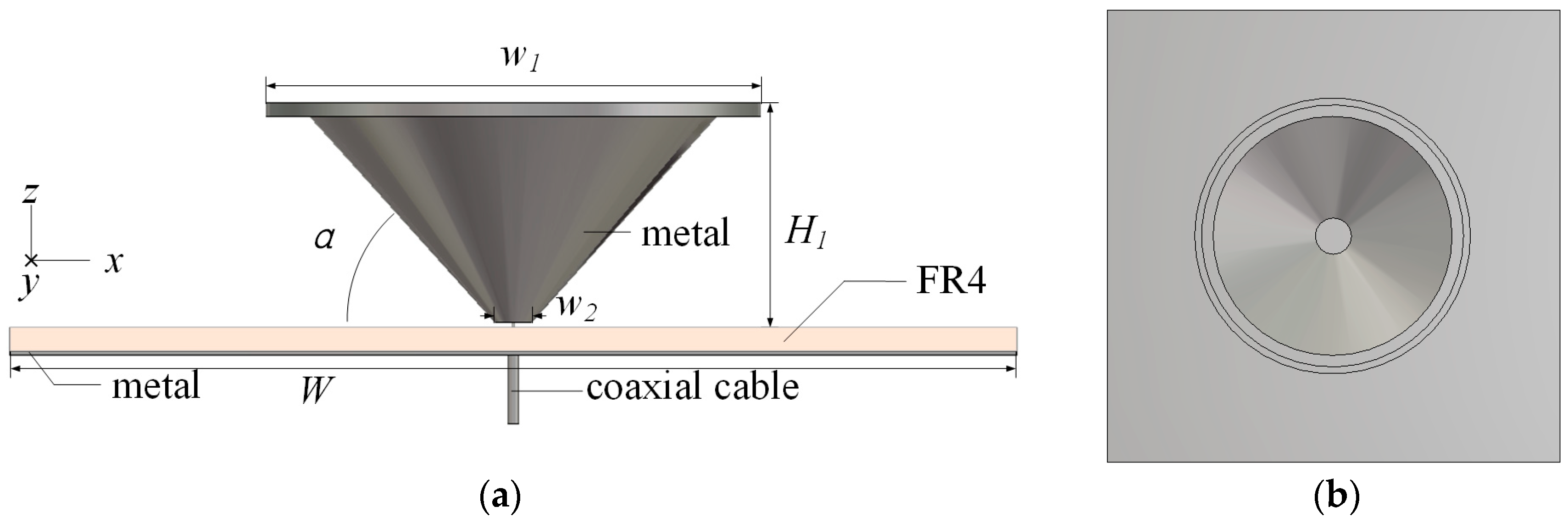
2.1. Bowl-Shape Monopole Antenna Design

A metal cone antenna Design 1 is first proposed, as shown in Figure 2, which consists of the metal bowl structure, reflective ground, and a coaxial cable. In order to achieve a lightweight, the inner part of the cone monopole is removed without affecting the radiation performance. The thickness of the metal to make the bowl structure is 0.5 mm.
To further analyze the working mechanism of the monopole antenna, Figure 3 shows the current distribution of Design 1 at 2.4 GHz, 6 GHz, and 11 GHz. It can be seen that the current is mainly distributed on the outer surface of the hollow cone, so the internal structure of the monopole has little influence on the reflection coefficient and radiation. The reflection coefficients of the solid conical and hollow conical structures are also compared in Figure 4a to prove this. The uniformly distributed current along the bowl structure at the same height leads to an omnidirectional radiation pattern.
The IMBW for S11 < −10 dB of the monopole antenna is 2.08–12.43 GHz, which is mainly affected by the bowl structure of the monopole. The study of the angle α is shown in Figure 4. With the variation of α, the structure of the antenna changes, resulting in the change of the antenna impedance, which affects the impedance bandwidth. The IMBWs of the three angles are 2.26–13, 2.06–13, and 2.06–12.67 GHz. When the α is close to 45°, a wider IMBW and lower reflection coefficient can be obtained.
With the increase of α, it is obvious that the IMBW between the 1.89 and 10 GHz frequency band improves, while the impedance matching of 10–12 GHz becomes worse. To achieve a wide IMBW, α = 45° is selected.

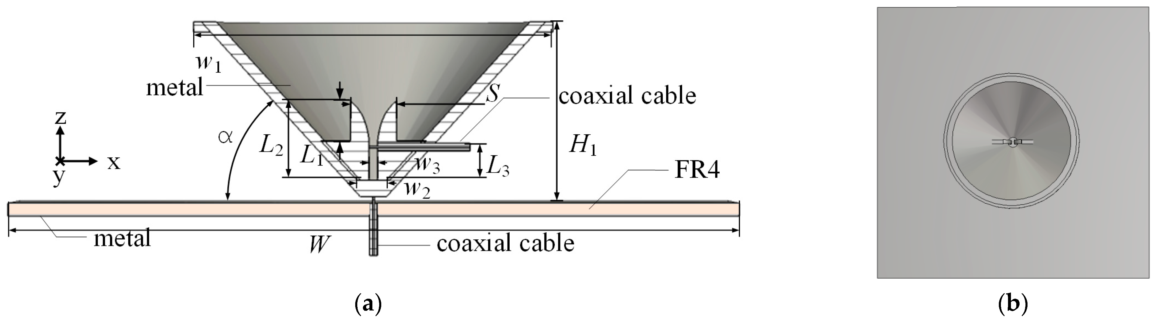
2.2. Vivaldi Antenna Design

To enable the designed antenna to cover the high-frequency frequency band, a metal Vivaldi antenna is placed inside the antenna Design 1 to form Design 2. The structure of Design 2 is shown in Figure 5. The feeding structure of Design 2 uses the lateral coaxial cable. The inner conductor of this coaxial cable is connected to one ridge of the Vivaldi antenna, and the outer conductor is connected to the other ridge, which facilitates the integration and processing of the Vivaldi antenna and monopole antenna.
The expression equation for the exponential opening curve of the Vivaldi antenna is expressed as follows (C1 and C2 are constants, and the α is the curvature of the groove line of the Vivaldi antenna) [31]:
x ( z ) = C 1 e α z + C 2
In order to obtain a wide IMBW, the study of the Vivaldi antenna’s key parameters is investigated. The working bandwidth of the Vivaldi antenna is mainly determined by the S and w3, which are the opening width at both ends of the exponential groove. The S and w3 are about half the wavelength of the cut-off frequencies of 21.02 and 29.6 GHz. In addition, the impedance-matching performance of the antenna is related to the length L1 of the exponential conical groove and L3, which represents the position of the coaxial cable feeding structure.
Combined with the theoretical basis, the parameter L1 is analyzed to obtain a wider IMBW. Figure 6 shows the reflection coefficients of Design 2 with different L1, L3, and w3, indicating that two deep resonances at 25 and 29 GHz are generated within the operating bandwidth. When w3 increases, it can be seen that the low cut-off frequency of IMBW shifts to a higher frequency. When L1 increases, the overall working bandwidth of the antenna moves to the low frequency. Finally, L1 = 6, L3 = 5, and w3 = 1.3 are selected, and the optimized IMBW of the Vivaldi antenna is 21.02–29.6 GHz (8.58 GHz, 33.8%).
To better analyze the working mechanism of Design 2, the electric field distribution of the antenna at 25 GHz is analyzed, and the corresponding electric field distribution is exhibited in Figure 7. It can be observed that when only the Vivaldi antenna structure exists, the energy radiates from the exponential gap to the opening of the antenna. The radiation field radiates in a large angle range, resulting in a sphere wave. By adding the hollow bowl around the Vivaldi antenna, the energy is more concentrated, which can be seen in Figure 7b. The electric field of the antenna in the maximum radiation direction is nearly the same as a plane wave after loading the metal bowl structure. There is negligible electric field distribution outside the metal bowl structure, and the radiation energy of the antenna is relatively more concentrated along the z-axis direction. As Figure 8 shows, the realized gain of Design 2 in the operating band is obviously higher than the one without loading the hollow cone structure, which proves the cone structure’s function of concentrating energy.

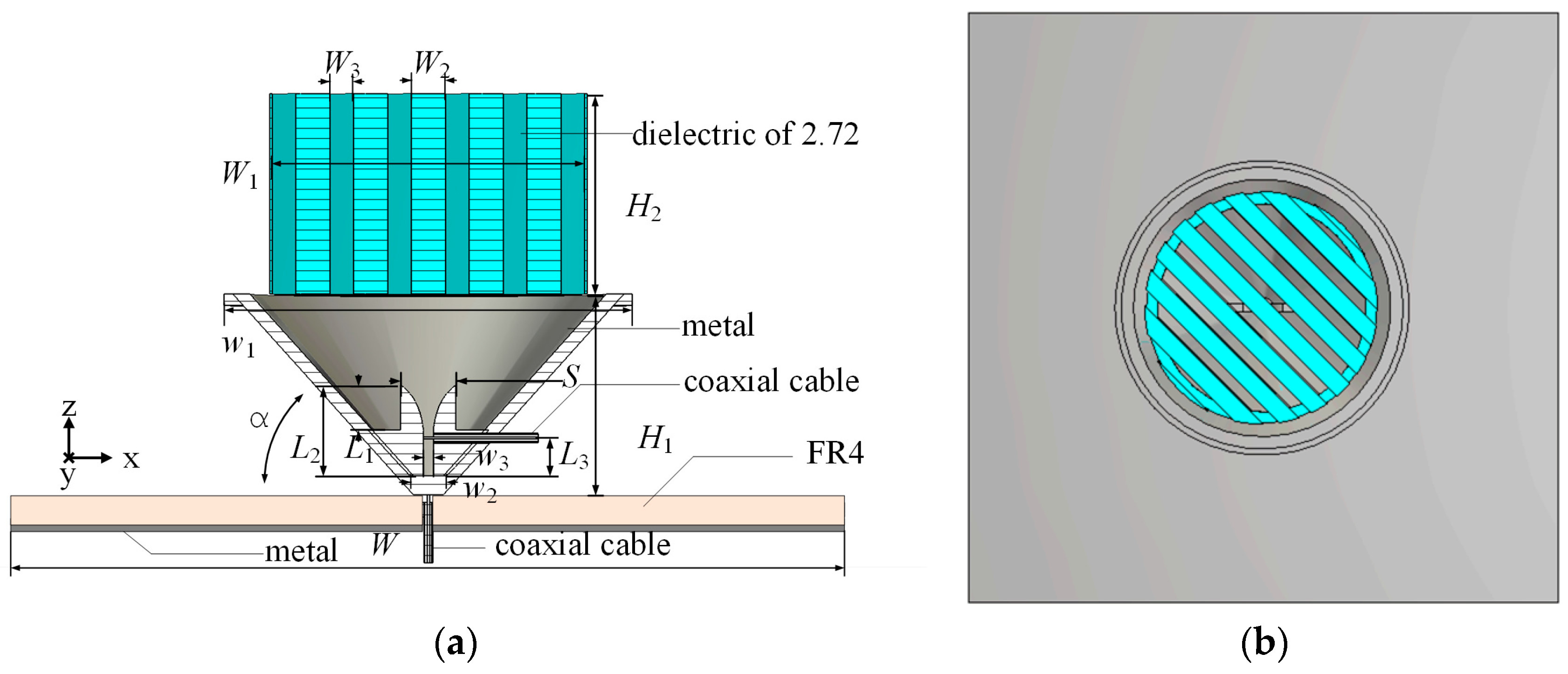
2.3. Medium Polarization Converter Design

The circularly polarized antenna can receive arbitrary polarization of linear polarization wave, which helps to solve the issue of polarization mismatch, and it also has advantages in inhibiting multi-path interference. There are many novel polarization converter designs. In this paper, the proposed circular polarized antenna is designed by adding a suitable dielectric polarization converter to achieve circular polarization.
The medium polarization converter model used in this paper is shown in Figure 9. The medium polarization converter is placed above antenna Design 2, which can convert the linear polarization to the circular polarization in the desired band. It consists of medium grid slabs of width W2 and air gaps of width W3. As shown in Figure 1 and Figure 9, the size of the converter is π × 1.942 × 1.9 λ02 at 21.6 GHz. The dielectric constant of the selected medium material is 2.72, which can be fabricated by 3D printing.
The medium polarization converter can turn the linear polarization waves emitted by the Vivaldi antenna into circular polarization waves. The medium polarization converter is placed directly above the monopole cone antenna, and its slabs form an angle of 45° along with the Vivaldi antenna. In the xoy plane shown in Figure 9a, the direction of −45 degrees from the x-axis is defined as the u direction, and the direction of 45 degrees from the x-axis is defined as the v direction, as shown in the figure. The linear polarized electric field of the Vivaldi antenna enters the circular polarization converter. Therefore, the electric field is decomposed into two orthogonal electric fields along the u and v directions, which are indicated as Eu and Ev. Because the different structural composition of the polarizer along the u and v directions leads to different equivalent dielectric constants in the two paths, the two electric fields in the u and v directions produce a phase difference of 90°. The equivalent dielectric constant in the direction of the medium polarization converter of the u direction can be written as [30]
ε u = ε 1 W 2 + ε 2 W 3
where ε1 and ε2 are the relative permittivity of the air and the medium, respectively. The equivalent dielectric constant in the v direction can be written as [30]
ε v = ε 1 ε 2 ε 1 W 2 + ε 2 W 3
Therefore, the phase difference between them can be written as
α = Δ β H 2 = ( β u β v ) H 2 = 2 π f H 2 c ( ε u ε v )
where βu and βv are the phase constants in the u and v directions, respectively. H2 represents the height of the medium polarization converter. A circular polarization wave can be generated when two orthogonal linear polarization waves are of the same magnitude and have a phase difference of ±90°. According to the above equation, the circular polarization radiation can be realized by adjusting the medium slabs and air widths to control the phase difference of the electric field in the u and v directions.
The medium polarization converter designed in this paper can not only convert the Vivaldi antenna from linear polarization to circular polarization but also improve the radiation gain of the Vivaldi antenna. As Figure 9b shows, when the electromagnetic wave of the Vivaldi antenna is transmitted to free space along the +z axis direction through a medium polarization converter, the medium does not change the propagation path of the wave. However, when the wave from the bottom is oblique into the medium polarization converter, the wave, after two refractions, will converge in an axial direction according to Snell’s law, which will improve the gain.
Figure 10a shows the high-frequency reflection coefficient comparison of the Vivaldi antenna in the hollow cone with and without the polarization converter. It can be seen that the addition of the medium polarization converter causes little fluctuation in the reflection coefficient of the Vivaldi antenna, but the working bandwidth does not change significantly. The IMBW of the antenna is 21.6–29.6 GHz (8 GHz, 31.2%).
The gain of the Vivaldi antenna with and without a polarization converter is shown in Figure 10b. Before incorporating the medium polarization converter, the Vivaldi antenna can achieve a maximum gain of 17 dBi at 29 GHz, and the gain within the bandwidth is relatively stable. Adding the medium polarization converter helps to improve the gain consistently across the entire working bandwidth. With the addition of the polarization converter, the axial ratio is less than 3 dB within 21.2–29.9 GHz, which proves that the proposed antenna has good circular polarization radiation ability in the high-frequency band. The peak gain of the proposed antenna is 18.9 dBi, and the gain fluctuation in the whole bandwidth is relatively flat, which is less than 3 dBi within the axial ratio bandwidth (ARBW) of 21.2–29.9 GHz. The gain within the ARBW is higher than 16 dBi. The efficiency across the 2.09–11.61 GHz (9.52 GHz, 138.9%) and 21.6–29.6 GHz (8 GHz, 31%) are higher than 89.4% and 84%, respectively, as shown in Figure 10c.

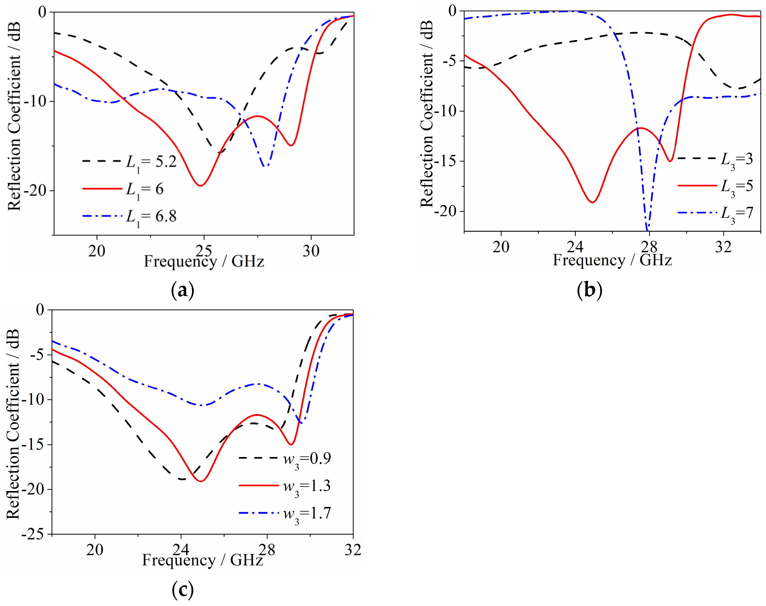
3. Results and Discussion

The simulated reflection coefficient of the proposed antenna is shown in Figure 11. The low-frequency IMBW of the proposed antenna is similar to that of Design 1 and Design 2 (Design 1 is the monopole antenna, and Design 2 is the monopole antenna loaded with Vivaldi antenna). The Vivaldi antenna and the medium polarization converter have a slight impact on the reflection coefficient of the monopole antenna, and the final working bandwidth is 2.09–11.61 GHz (9.52 GHz, 138.9%), meeting the requirement of the ultra-wideband (Ultra-Wide Band, UWB) frequency range. Figure 11b indicates that the isolation in the low- and high-frequency bands are higher than 46.5 and 58 dB, respectively. The medium polarizer has little effect on the high-frequency impedance matching, and the high-frequency IMBW covers 21.6–29.6 GHz (8 GHz, 31%). The axial ratio of the proposed antenna is shown in Figure 12a. The axial ratio is less than 3 dB within 21.2–29.9 GHz. The overall gain of the proposed antenna is shown in Figure 12b. The peak gain within 2.09–11.61 GHz is from 2.7 to 7.1 dBi, and the broadside gain within 21.6–29.6 GHz is from 16.1 to 18.8 dBi.
Figure 13 shows the radiation pattern at 2.4 GHz, 6 GHz, and 11 GHz, and Figure 14 depicts the normalized radiation pattern of the proposed antenna at 25 GHz and 29 GHz. It can be seen that the Vivaldi antenna realizes directional radiation across the high-frequency band, while the monopole antenna radiates an omnidirectional pattern across the low-frequency band. The cross-polarization of both the Vivaldi antenna and the monopole antenna is lower than −15 dB, while the front-to-back ratio of the Vivaldi antenna is lower than −30 dB. The proposed antenna possesses a stable radiation pattern.

4. Design Guideline and Comparison

According to the above analysis, the proposed antenna design principle can be given as follows:
(1)
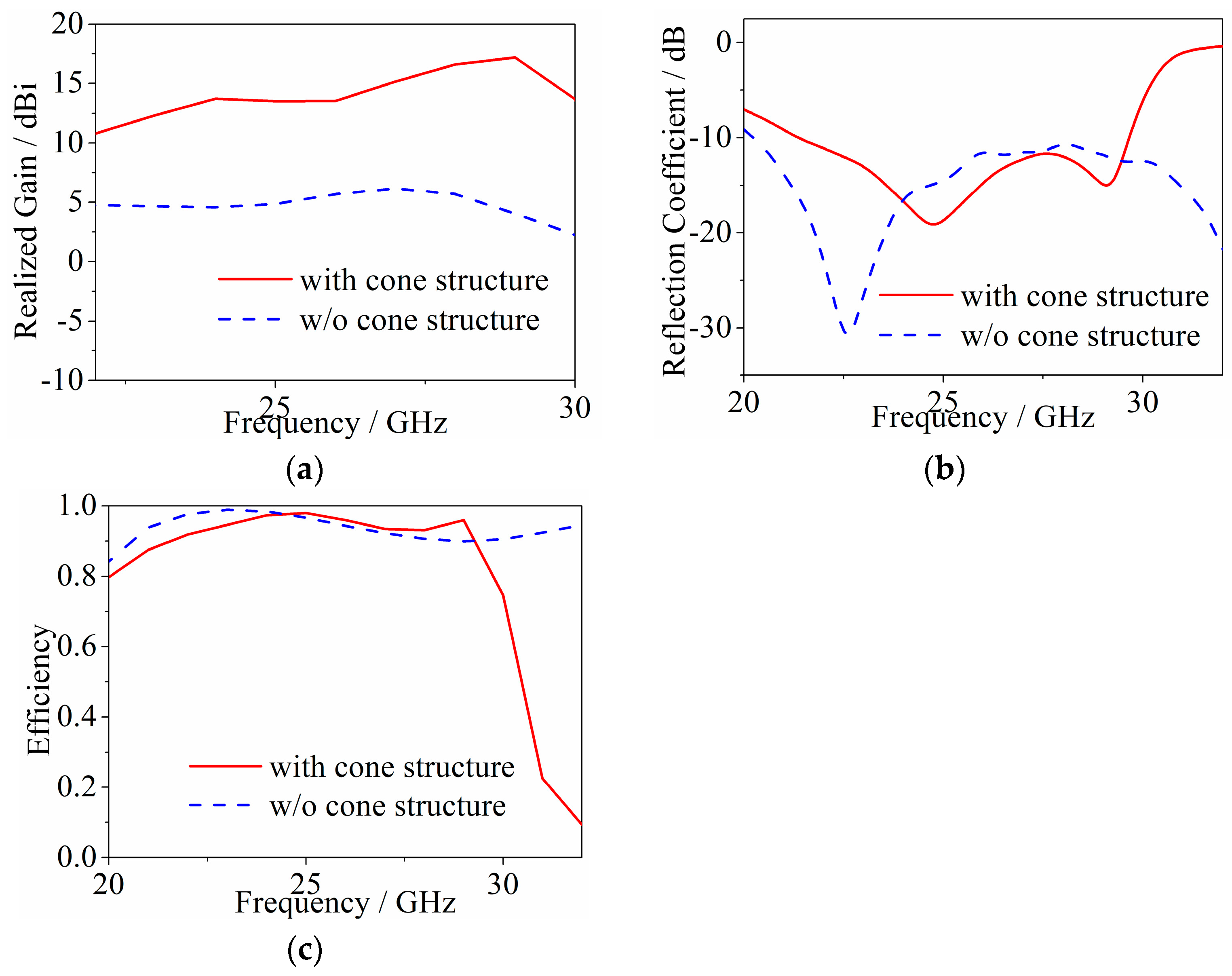
The omnidirectional monopole antenna is designed based on the cone structure to work in the low-frequency band. Then, the internal metal is removed without affecting the radiation performance;
(2)
A Vivaldi antenna made of metal is designed to be located at the bottom of the cone to work in the high-frequency band. The addition of the Vivaldi antenna has no effect on the radiation performance of the monopole antenna;
(3)
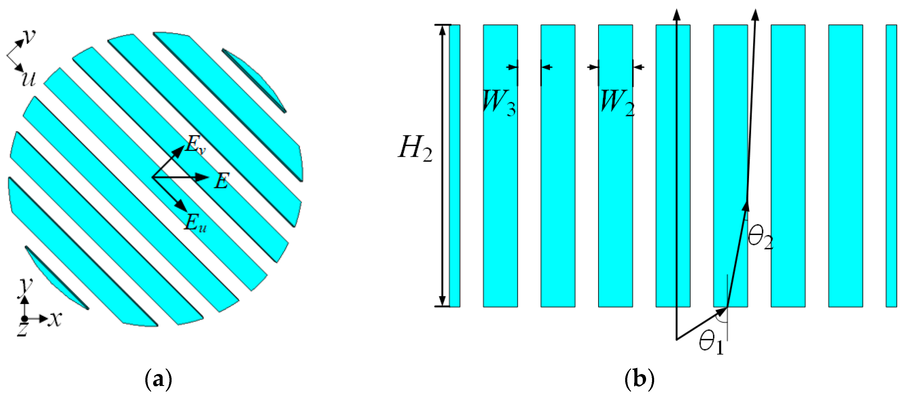
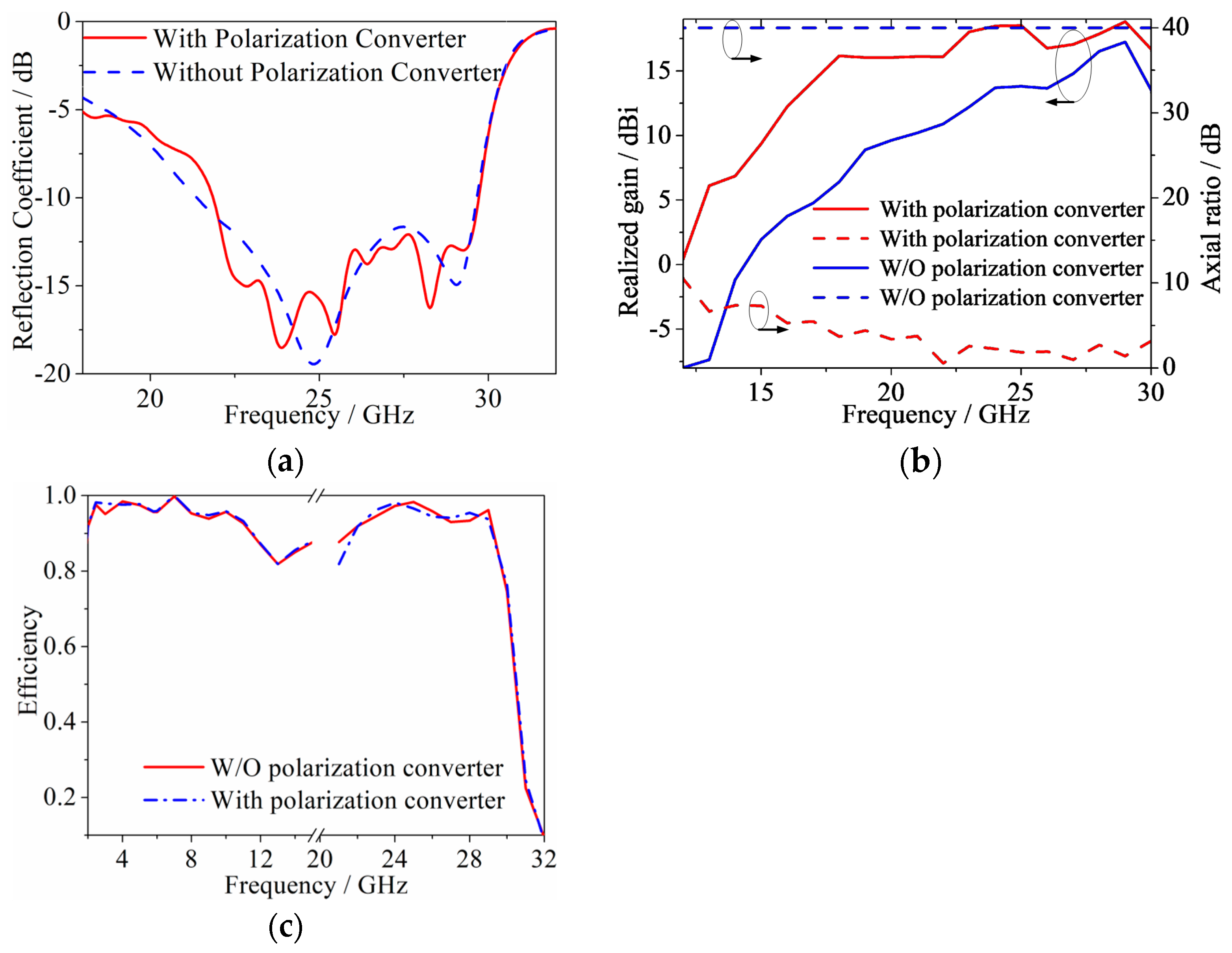
Design the circular polarization medium converter and adjust the proportion of medium and air to ensure that the axis ratio of the Vivaldi antenna is less than 3 dB. Then, the circular polarization medium converter is placed above the cone monopole antenna.
Finally, the proposed antenna is compared with other works in Table 2. It can be seen that most antennas exhibit dual LP directional radiation in the dual bands except [5]. The proposed antenna shows wider bandwidths than others, and both polarization and radiation pattern diversities are achieved.

5. Conclusions

In this paper, a hollow cone monopole low-frequency antenna is designed, then a metal high-frequency Vivaldi antenna is added at the bottom of the cone, which can be fabricated through the 3D printing technique. In the end, a dielectric polarization converter is added above the cone without affecting the radiation performance of the monopole antenna, which realizes the transformation from linear polarization to circular polarization of the Vivaldi antenna. At the same time, the dielectric polarization converter can also improve the broadside gain of the Vivaldi antenna. The working bandwidth of the proposed antenna is 2.09–11.61 GHz (9.52 GHz, 138.9%) and 21.6–29.6 GHz (8 GHz, 31%), which can be a good candidate for multi-band communication systems.

Author Contributions

Conceptualization, C.Z.; methodology, J.C. and T.G.; validation, T.G. and J.C.; formal analysis, J.C. and D.H.; investigation, T.G. and D.H.; data curation, T.G. and D.H.; writing, J.C., T.G. and C.Z.; supervision, C.Z.; project administration, C.Z. All authors have read and agreed to the published version of the manuscript.

Funding

This research was funded by the Natural Science Foundation of China under Grant 62371088 and Grant U23A20290, the Fundamental Research Funds for the Central Universities under Grant DUT24ZD126, and a grant from the National Key Laboratory of Electromagnetic Information Control and Effects under Grant HX20231736.

Institutional Review Board Statement

Not applicable.

Informed Consent Statement

Not applicable.

Data Availability Statement

Data is contained within the article.

Conflicts of Interest

The authors declare no conflicts of interest.

References

  1. Hao, J.N.; Feng, L.Y.; Ji, W.S.; Liu, Y. Dual-Wideband Dual-Frequency Antenna With Large Frequency Ratio for 5G Applications. IEEE Trans. Antennas Propag. 2024, 72, 1887–1892. [Google Scholar] [CrossRef]
  2. Yang, X.; Ge, L.; Ji, Y.; Zeng, X.R.; Li, Y.J.; Ding, C. An integrated tri-band antenna system with large frequency ratio for WLAN and WiGig applications. IEEE Trans. Ind. Electron. 2021, 68, 4529–4540. [Google Scholar] [CrossRef]
  3. Feng, L.Y.; Leung, K.W. Dual-fed hollow dielectric antenna for dual frequency operation with large frequency ratio. IEEE Trans. Antennas Propag. 2017, 65, 3308–3313. [Google Scholar] [CrossRef]
  4. Feng, L.Y.; Leung, K.W. Dual-frequency folded-parallel-plate antenna with large frequency ratio. IEEE Trans. Antennas Propag. 2016, 64, 340–345. [Google Scholar] [CrossRef]
  5. Xiao, F.; Lin, X.; Su, Y.H. Dual-band structure-shared antenna with large frequency ratio for 5G communication applications. IEEE Antennas Wirel. Propag. Lett. 2020, 19, 2339–2343. [Google Scholar] [CrossRef]
  6. Ding, Y.R.; Cheng, Y.J. A tri-band shared-aperture antenna for (2.4, 5.2) GHz Wi-Fi application with MIMO function and 60 GHz Wi-Gig application with beam-scanning function. IEEE Trans. Antennas Propag. 2020, 68, 1973–1981. [Google Scholar] [CrossRef]
  7. Xiang, B.J.; Zheng, S.Y.; Wong, H.; Pan, Y.M.; Wang, K.X.; Xia, M.H. A flexible dual-band antenna with large frequency ratio and different radiation properties over the two bands. IEEE Trans. Antennas Propag. 2018, 66, 657–667. [Google Scholar] [CrossRef]
  8. Feng, L.Y.; Hao, J.N.; Zhao, H.K.; Ji, W.S.; Liu, Y. Design of Singly Fed Dual-Band Antenna With a Large Frequency Ratio by Introducing a Monopole Mode to Yagi–Uda Antenna. IEEE Trans. Antennas Propag. 2023, 71, 9042–9047. [Google Scholar] [CrossRef]
  9. Ikram, M.; Nguyen-Trong, N.; Abbosh, A. Multi-band MIMO microwave and millimeter antenna system employing dual-function tapered slot structure. IEEE Trans. Antennas Propag. 2019, 67, 5705–5710. [Google Scholar] [CrossRef]
  10. Ren, J.; Zuo, M.M.; Zhang, B.; Du, X.Y.; Chen, Z.; Liu, Y. Large frequency ratio Vivaldi antenna system with low frequency gain enhancement utilizing dual-function taper slot. IEEE Trans. Antennas Propag. 2022, 70, 4854–4859. [Google Scholar] [CrossRef]
  11. Sadananda, K.G.; Abegaonkar, M.P.; Koul, S.K. Gain Equalized Shared-Aperture Antenna Using Dual-Polarized ZIM for mmWave 5G Base Stations. IEEE Antennas Wirel. Propag. Lett. 2019, 18, 1100–1104. [Google Scholar] [CrossRef]
  12. Hussain, R.; Abou-Khousa, M.; Iqbal, N.; Algarni, A.; Alhuwaimel, S.I.; Zerguine, A.; Sharawi, M.S. A Multiband Shared Aperture MIMO Antenna for Millimeter-Wave and Sub-6GHz 5G Applications. Sensors 2022, 22, 1808. [Google Scholar] [CrossRef]
  13. Zhang, J.F.; Cheng, Y.J.; Ding, Y.R.; Bai, C.X. A Dual-Band Shared-Aperture Antenna With Large Frequency Ratio, High Aperture Reuse Efficiency, and High Channel Isolation. IEEE Trans. Antennas Propag. 2019, 67, 853–860. [Google Scholar] [CrossRef]
  14. Yang, J.; Cao, Z.; Meng, H.; Li, Q.; Li, Y. A Mutually Enhanced Ka/W Dual-Band Shared-Aperture Horn Antenna. IEEE Trans. Antennas Propag. 2024, 72, 1234–1240. [Google Scholar] [CrossRef]
  15. Ren, J.; Wang, Z.; Sun, Y.X.; Huang, R.; Yin, Y. Ku/Ka-Band Dual-Frequency Shared-Aperture Antenna Array With High Isolation Using Frequency Selective Surface. IEEE Antennas Wirel. Propag. Lett. 2023, 22, 1736–1740. [Google Scholar] [CrossRef]
  16. Ali, A.; Awan, M.N.; Malik, W.A.; Chaudhry, S.Y.; Hidayatullah; Haider, J. A Compact and High Gain X/Ku Band Shared Aperture Antenna Array With Enhanced Inter-Band and Cross-Band Isolation. IEEE Access 2024, 12, 146137–146146. [Google Scholar] [CrossRef]
  17. Surse, K.; Gopika, R.; Saha, C. Dual-Band Shared Aperture Antenna (SAA) Array for Feedback-Enabled WPT Application. In Proceedings of the 2022 IEEE Microwaves, Antennas, and Propagation Conference (MAPCON), Bangalore, India, 12–16 December 2022; pp. 750–753. [Google Scholar]
  18. Li, T.; Chen, Z.N. Metasurface-based shared-aperture 5G S-/K-band antenna using characteristic mode analysis. IEEE Trans. Antennas Propag. 2018, 66, 6742–6750. [Google Scholar] [CrossRef]
  19. Smith, T.; Gothelf, U.; Kim, O.S.; Breinbjerg, O. An FSS-backed 20/30 GHz circularly polarized reflect array for a shared aperture L-and Ka-band satellite communication antenna. IEEE Trans. Antennas Propag. 2014, 62, 661–668. [Google Scholar] [CrossRef]
  20. Li, T.; Chen, Z.N. Shared-surface dual-band antenna for 5G applications. IEEE Trans. Antennas Propag. 2020, 68, 1128–1133. [Google Scholar] [CrossRef]
  21. Li, D.; Shen, Z.; Li, E.P. Spurious-free dual-band band-pass frequency selective surfaces with large band ratio. IEEE Trans. Antennas Propag. 2019, 67, 1065–1072. [Google Scholar] [CrossRef]
  22. Zhou, C.F.; Yuan, S.S.; Li, H.; Wang, B.; Wong, H. Dual-band shared-aperture antenna with bi-functional metasurface. IEEE Antennas Wirel. Propag. Lett. 2021, 20, 2013–2017. [Google Scholar] [CrossRef]
  23. Zhu, Y.; Chen, Y.; Yang, S. Decoupling and low-profile design of dual-band dual-polarized base station antennas using frequency-selective surface. IEEE Trans. Antennas Propag. 2019, 67, 5272–5281. [Google Scholar] [CrossRef]
  24. Zhu, J.; Yang, Y.; Liao, S.; Li, S.; Xue, Q. Dual-band aperture-shared fabry-perot cavity-integrated patch antenna for millimeter-wave/Sub-6 GHz communication. IEEE Antennas Wirel. Propag. Lett. 2022, 21, 868–872. [Google Scholar] [CrossRef]
  25. Zou, J.; Zhao, Y.; Yang, X.; Ge, L.; Sun, Y.X. Dual-Band Dual-Polarized Shared-Aperture Grid Antenna With Large Frequency Ratio. IEEE Antennas Wirel. Propag. Lett. 2023, 22, 1513–1517. [Google Scholar] [CrossRef]
  26. Guo, Q.-Y.; Lin, Q.W.; Wong, H. A high gain millimeter-wave circularly polarized fabry–pérot antenna using prs-integrated polarizer. IEEE Trans. Antennas Propag. 2021, 69, 1179–1183. [Google Scholar] [CrossRef]
  27. Wang, K.X.; Wong, H. A wideband millimeter-wave circularly polarized antenna with 3-D printed polarizer. IEEE Trans. Antennas Propag. 2017, 65, 1038–1046. [Google Scholar] [CrossRef]
  28. Ding, C.; Luk, K.-M. Wideband high-gain circularly polarized antenna using artificial anisotropic polarizer. IEEE Trans. Antennas Propag. 2019, 67, 6645–6649. [Google Scholar] [CrossRef]
  29. He, Y.Q.; Zhao, X.Y.; Zhao, L.Y.; Fan, Z.X.; Wang, J.K.; Zhang, L. Design of broadband double-ridge horn antenna for millimeter-wave applications. IEEE Access 2021, 9, 118919–118926. [Google Scholar] [CrossRef]
  30. Wang, K.X.; Wong, H. Design of a wideband circularly polarized millimeter-wave antenna with an extended hemispherical lens. IEEE Trans. Antennas Propag. 2018, 66, 4303–4308. [Google Scholar] [CrossRef]
  31. Zhou, Q.H.; Zhang, J.H.; Zheng, X.; Zhang, J.F.; Zhang, Z.H.; Huang, L. A High-Gain Antipodal Vivaldi Antenna Operating at 1 GHz to 40 GHz for Photonic-Assisted Receiver. IEEE Antennas Wirel. Propag. Lett. 2024, 23, 3068–3072. [Google Scholar] [CrossRef]
Figure 1. Geometry of the proposed antenna: (a) side view, and (b) top view.
Applsci 15 00878 g001
Figure 2. (a) Side view, and (b) top view of monopole antenna Design 1.
Applsci 15 00878 g002
Figure 3. Current distribution of monopole antenna Design 1 of (a) side view of 2.4 GHz, (b) top view of 2.4 GHz, (c) side view of 6 GHz, (d) top view of 6 GHz, (e) side view of 7.5 GHz, (f) top view of 7.5 GHz.
Applsci 15 00878 g003
Figure 4. (a) Reflection coefficient comparison between solid and hollow cone structure, (b) simulated reflection coefficient at different parameter α.
Applsci 15 00878 g004
Figure 5. Structure of Design 2, (a) side view, and (b) top view.
Applsci 15 00878 g005
Figure 6. Simulated reflection coefficients of the Vivaldi antenna at different parameters (a) L1, (b) L3, and (c) w3.
Applsci 15 00878 g006
Figure 7. Vivaldi antenna electric field distribution, (a) without, and (b) with cone structure.
Applsci 15 00878 g007
Figure 8. Comparison of Design 2 and Design 2 without single cone structure in (a) realized gain, (b) reflection coefficient, and (c) efficiency.
Applsci 15 00878 g008
Figure 9. Medium polarization converter structure and electromagnetic wave passage path. (a) Top view, and (b) side view.
Applsci 15 00878 g009
Figure 10. Comparison of Vivaldi antennas with polarization converter and without polarization converter in (a) reflection coefficients, (b) axial ratio and realized gain, and (c) efficiency.
Applsci 15 00878 g010
Figure 11. (a) Comparison of reflection coefficients of Design 1, Design 2, and proposed antenna, (b) transmission coefficient of the proposed antenna.
Applsci 15 00878 g011
Figure 12. (a) Axial ratio, (b) peak gain of the proposed antenna.
Applsci 15 00878 g012
Figure 13. Radiation patterns of the proposed antenna in the E-plane (xoz-plane) and H-plane (xoy-plane). (a) Theta = 90° at 2.4 GHz, (b) Phi = 0° at 2.4 GHz, (c) Theta = 90° at 6 GHz, (d) Phi = 0° at 6 GHz, (e) Theta = 90° at 11 GHz, (f) Phi = 0° at 11 GHz. (—sim. co-pol.; - - -: sim. cross-pol.).
Applsci 15 00878 g013aApplsci 15 00878 g013b
Figure 14. Radiation patterns of the proposed antenna in the E-plane (xoz-plane) and H-plane (yoz-plane). (a) Phi = 0° at 25 GHz; (b) Phi = 90° at 25 GHz; (c) Phi = 0° at 29 GHz; and (d) Phi = 90° at 29 GHz. (—: sim. co-pol.; - - -: sim. cross-pol).
Applsci 15 00878 g014
Table 1. Optimized parameter values for the proposed antenna.
ParametersValue
L16 mm
L212 mm
L35 mm
W110 mm
W142 mm
W23.2 mm
W32.2 mm
w154 mm
w22 mm
w31.3 mm
S7.31 mm
H127.5 mm
H226.5 mm
α45°
Table 2. Comparison of different dual-band antennas.
Ref.IMBWRadiation PatternPeak Gain/dBiIsolation
/dB
PolarizationSize
λ03
[1]1.61–2.44 GHz (40.9%)
20–36.4 GHz (58.2%)
directional/
directional
10.2/17.495/30LP/LP0.805 × 0.805 × 0.195
[3]2.30–3.20 GHz (32.73%)
23.64–25.06 GHz (5.83%)
directional/
directional
8.23/18.2/LP/LP0.767 × 0.767 × 0.18
[4]2.37–2.55 GHz (7.3%)
23.92–24.46 GHz (2.23%)
directional/
directional
7.23/11.2670/33LP/LP0.79 × 0.79 × 0.194
[5]3.02−5.03 GHz (49.94%)
27.3−28.8 GHz (5.35%)
omnidirectional/directional2.55/9.630/30LP/LP0.443 × 0.302 × 0.005
[14]3.2–4.05 GHz (23.45%)
25.22–26.46 GHz (4.8%)
directional/
directional
10.88/22.475/24LP/LP1.067 × 1.067 × 0.051
[16]3.2–4.05 GHz (23.45%)
26.8–29.55 GHz (9.76%)
directional/
directional
10.44/14.674/19LP/LP0.461 × 0.461 × 0.063
[18]2.12–2.75 GHz (25.8%)
5.69–5.91 GHz (3.8%)
directional/
directional
7.9/11.727/20LP/LP0.495 × 0.495 × 0.161
[20]2.40–2.48 GHz (3.28%)
27.7–28.1 GHz (1.43%)
directional/
directional
8/1538/25LP/LP0.6 × 0.6 × 0.033
[21]3.41–3.59 GHz (5.14%)
26.62–30.26 GHz (12.8%)
directional/
directional
8.75/12.7924.2/18.4LP/LPπ × 0.3982 × 0.321
This work2.09–11.61 GHz (138.9%)
21.6–29.6 GHz (31%)
Omnidirectional/directional7.1/18.846.5/58LP/CP0.76 × 0.76 × 0.37
Disclaimer/Publisher’s Note: The statements, opinions and data contained in all publications are solely those of the individual author(s) and contributor(s) and not of MDPI and/or the editor(s). MDPI and/or the editor(s) disclaim responsibility for any injury to people or property resulting from any ideas, methods, instructions or products referred to in the content.

