Article

Transient Vibration Loads Characteristics Analysis of Variable Speed Rotor

National Key Laboratory of Helicopter Aeromechanics, China Helicopter Research Design Institute, Jingdezhen 333001, China
*
Author to whom correspondence should be addressed.
Appl. Sci. 2025, 15(19), 10493; https://doi.org/10.3390/app151910493
Submission received: 27 August 2025 / Revised: 18 September 2025 / Accepted: 23 September 2025 / Published: 28 September 2025

Abstract

To investigate the rotor vibration loads during the variable speed transient process, a transient rotor aeroelastic method based on the medium beam deformation theory and Hamilton’s principle is developed to simulate the rotor transient dynamic loads in the transient state. Different variable rotor speed strategies in different forward flight cases are investigated. Specifically, parameter characteristic analyses are conducted to better understand the transient rotor vibration load characteristics. Results indicate that there is significant overshoot in rotor hub torque at both the start and end of the rotor speed changing time. The maximum total overshoot of hub torque is 1940 N·m within 0.2 s at 400 km/h rotor speed decrease transient process. Different from the previous work, the impulsive features are primarily caused by the linear angular acceleration, while the transient inertial moment in hub torque is caused by the 1st frequency blade root lag bending moment. The overshoot of rotor hub torque during the transient process is mainly associated with angular acceleration, whereas flight speed and rotor thrust have minimal impact. The value of overshoot/time can be reduced by 98.6% at most in three angular acceleration strategies, and it can be reduced by 92.7% at most in three transient times. Adjusting the rotor pitch attitude during the transient state appears to be an effective strategy for reducing hub torque.

1. Introduction

Military and commercial customers continue to express a strong interest in aircraft that combine high speed capability with the hover and low speed efficiencies and flying qualities of conventional helicopters [1]. With the development of the green low altitude economy, electric vertical takeoff and landing (eVTOL) aircraft have experienced rapid development [2]. Whether high-speed helicopters (coaxial helicopters [3], tilt-rotor aircraft [4], compound helicopters [5], or eVTOL aircraft [6], the future development of rotorcraft is closely tied to variable rotor speed technology. A detailed analysis of the transient rotor vibration load characteristics of variable rotor speed rotors is essential. However, new aeroelastic dynamics problems will arise during the variable rotor speed transient process, such as rotor vibration loads, transient rotor drivetrain coupling, or transient rotor electrical drivetrain coupling.
Graham [7] conducted a detailed analysis of the airloads, blade loads, and performance of variable RPM (Revolutions Per Minute) rotors at high advance ratios. The results indicate that reverse flow and asymmetry of airloads are severe but can be effectively mitigated by reducing rotor speed. Felix and Christoph [8] analyzed the influence of the drivetrain on blade loads, demonstrating that rotor speed fluctuations significantly affect blade lead lag loads. Wang et al. [9] carried out a series of experiments to investigate the behavior of variable RPM rotors at high advance ratios, revealing that blade structural load levels are substantially higher. However, current research on transient aeroelasticity remains limited. Han et al. [10] developed a transient aeroelastic response model and summarized the rotor aeroelastic response with ship motion; however, the details of transient rotor vibration loads under variable rotor speed conditions have not been adequately simulated. Yu et al. [11] analyzed the aeroelastic characteristics of variable RPM rotors, showing that second-order blade loads on the rotor increase significantly at high speeds, although this study is limited to steady state conditions. Huang et al. [12] summarized the characteristics of blade transient section loads, but accurate simulation of hub torque details remains challenging. Zhao et al. [13] employed the Helios/RACS coupling model to investigate S-97 RAIDER flight loads during transient maneuvers, finding that time-varying RPM significantly influences blade lag bending moments. Constantin et al. [14] utilized the FLOWer/HOST coupling model to study X-3 flight loads at high speeds, discovering that level accelerations exceeded 2G in time-varying RPM transient high-speed flight tests. Carlos and Shannah [15] developed a coupled rotor motor dynamic model, demonstrating that the motor’s electrical characteristics and rotor inertias significantly influenced control system performance and handling quality metrics. Brenner et al. [16] introduced a rotor dynamic model integrated with an electric propulsion system, showing that the coupled simulation codes provided more accurate estimates of rotor transient responses. Changik et al. [17] employed variable RPM to induce small torque perturbations and utilized the damping effect of the main electric motor’s rotor torque to mitigate vibrations in a quad tiltrotor eVTOL. However, the rotor dynamics models in these studies were based on rigid blade assumptions, neglecting the dynamic loads induced by blade elastic deformation. Consequently, this paper aims to develop a transient rotor aeroelastic method that accounts for these effects.
In this paper, a transient rotor aeroelastic method is established to conduct a further study on the mechanism of transient vibration load characteristics. The kinetic energy resulting from the rotor angular acceleration is adopted in the virtual variation in kinetic energy, and the extra blade inertia forces and moment caused by rotor angular acceleration are taken into account to compute the rotor blade loads. Transient vibration loads are investigated in different variable RPM strategies in various forward flight cases. Different parameter analyses in the transient process are carried out to make a better understanding of the characteristics of transient rotor vibration loads, and some new conclusions are obtained. Meanwhile, some strategies for reducing hub torque overshoot are implemented to demonstrate the potential of rotor load reduction in the maneuvering state.

2. Methods

2.1. Transient Rotor Dynamic Method

The medium beam deformation beam model is adopted in the transient rotor dynamics based on the Euler–Bernoulli beam [18]. The medium deformation model is based on isotropic beam assumptions, ignoring the influence of temperature on the model. The Hamilton principle is adopted in the dynamic equation, which is shown below:
( δ U δ T δ W ) = 0
where δ U represents the virtual variation in strain energy, δ T represents the virtual variation in kinetic energy, δ W denotes the virtual work performed by external forces. The equation of virtual variation in strain energy δ U is written as Equation (2), where σ represents stress, ε represents strain, ( x , η , ζ ) denotes the spatial coordinates of a point on the blade in the deformation coordinate system, A denotes the sectional area of the blade in the undeformed coordinate system, R denotes rotor radius, x denotes the undeformed blade length coordinate. The equation of the virtual variation in kinetic energy δ T is written as Equation (2), where ( x , η , ζ ) represents blade linear density, V represents Space velocity at any point of the blade, which includes the flapping, lag and torsional motion. The equation of the virtual work performed by external forces δ W is written as Equation (2), where, L u , L v , L w respectively represent the external forces in blade axial u, lag deflection v, and flap deflection w, M denotes torsion in the torsional ϕ direction. The external forces are mainly from aerodynamic forces.
δ U = 0 R A ( σ x x ε x x + σ x η ε x η + σ η ζ ε η ζ ) d A d x δ T = 0 R A   ρ V · δ V   d A d x δ W = 0 R ( L u δ u + L v δ v + L w δ w + M ϕ δ ϕ ) d x
The kinetic energy includes blade rotational, flapping, shimmy, and torsional motions. The relative coordinate description method is adopted to describe any point in the blade space. Rotor speed Ω is assumed to be constant in traditional rotor dynamics models, thereby neglecting the kinetic energy variations during transient processes. Therefore, the virtual variation in kinetic energy in the transient rotor dynamics method must be considered, incorporating the kinetic energy changes associated with rotor speed during these transient events [12]. The extra equations can be written below (Equation (3)), where Ω ˙ represents angular acceleration, β P represents rotor pre-cone angle, e g represents blade section center of gravity offset from elastic axis, θ represents blade section pitch angle, ϕ represents elastic twist in deformed blade coordinate system, and v , w represent lag deflection and flap deflection in the blade section.
Δ T v = Ω ˙ β p w + Ω ˙ v e g cos θ + Ω ˙ w e g sin θ Ω ˙ x Δ T v = Ω ˙ v e g cos θ Δ T w = Ω ˙ β p v Ω ˙ β p e g cos θ Δ T w = Ω ˙ v e g sin θ Δ T ϕ ^ = Ω ˙ x e g sin θ + Ω ˙ ϕ ^ x e g cos θ Δ T F = Ω ˙ v 0 x v δ v + w δ w d ξ
The virtual work energy is contributed by the external load of the rotor blade, including the aerodynamic lift, drag, and pitch moment, which can be accurately modeled using the Leishman-Beddoes dynamic stall model, and the Pitt-Peters dynamic inflow model [19] is employed. The external load is a periodically varying dynamic load.
The 15 degree of freedom (DOF) beam element model is employed for the spatial discretization of the blade through the structural finite element analysis method. Each element comprises 12 end nodes and 3 internal nodes (as shown in Figure 1). Symbolic subscripts denote node numbers within the finite element, and symbols have been explained previously. The boundary conditions of the finite element model are determined by the configuration of the rotor hub, and the rotor hub is assumed to be a rigid body.
The mass matrix, damping matrix, stiffness matrix, and load column vector of each finite element unit are derived by the method of finite element discretization. Finally, the finite elements are assembled to form the final rotor transient dynamics equation of the rotor system (Equation (4)), where M represents the mass matrix, C represents the damping matrix, K represents the stiffness matrix, F represents the loads matrix, and q represents the dynamic response matrix.
M q ¨ + C q ˙ + K q = F
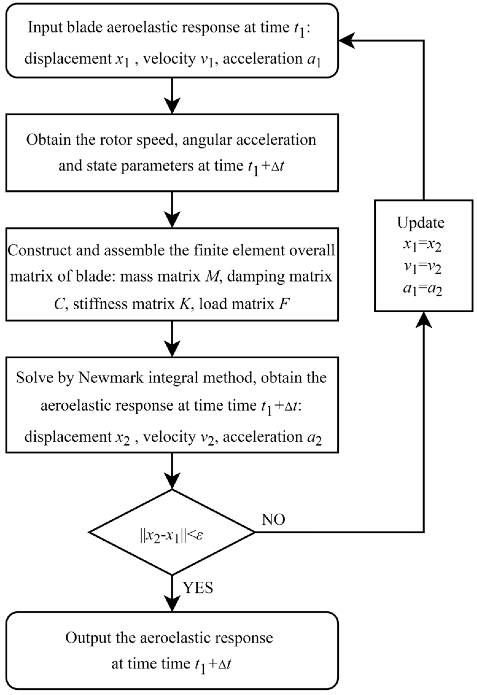
Newmark direct integration method combined with Newton-Raphson iteration is employed to solve the transient dynamic equations, which has been proved to be robust by engineering practice. Due to the time-varying nature of rotor speed, the transient aeroelastic response at each time instant is computed using a time-marching algorithm, with a fixed time step Δt = 0.01 s. The computational procedure for advancing the aeroelastic response is illustrated in Figure 2, where ε denotes the iterative convergence tolerance set to 0.005.

2.2. Transient Rotor Loads Method

The blade section loads contain blade aerodynamic and blade inertial loads. These loads are calculated using the force summation method (Equation (5)). At any given location x0 along the blade, the forces and moments per unit span in the undeformed reference frame are:
F x F y F z = x 0 1 L u L v L w d x , M x M y M z = x 0 1 M u L v w w 0 + L w v v 0 M v + L u w w 0 L w x + u x 0 u 0 M w L u v v 0 + L v x + u x 0 u 0 d x
where F x , F y , F z represent the blade section forces in the undeformed reference frame, and M x , M y , M z represent the blade section moment in the undeformed reference frame. By the transformation coordinate matrix, the hub loads are obtained from each blade root load.
The extra blade forces and moment caused by rotor speed in the transient process can be written below (Equation (6)), where m represents blade section mass per unit length, m k m 2 , m k m 1 2 , m k m 2 2 represent polar, normal, and chordwise mass moments of inertia.
Δ L u = m Ω ˙ v Ω ˙ ϕ ^ e g sin θ + Ω ˙ e g cos θ Δ L v = m Ω ˙ β p w Ω ˙ x + Ω ˙ v e g cos θ + Ω ˙ w e g sin θ Δ L w = m Ω ˙ β p v Δ M u = m Ω ˙ β p k m 2 Ω ˙ v ( k m 2 2 k m 1 2 ) cos θ sin θ Ω ˙ w ( k m 2 2 sin 2 θ + k m 1 2 cos 2 θ ) + Ω ˙ v e g sin θ Δ M v = m Ω ˙ ( k m 2 2 k m 1 2 ) cos θ sin θ 2 Ω Ω ˙ β p ( k m 2 2 sin 2 θ + k m 1 2 cos 2 θ ) Ω ˙ v e g sin θ Δ M w = m Ω ˙ ( k m 2 2 sin 2 θ + k m 1 2 cos 2 θ ) ( Ω ˙ v Ω ˙ x v ) e g cos θ + Ω ˙ x w e g sin θ

2.3. Rotor Trim Model

To achieve a specific value of rotor thrust, roll moment, and pitch moment balance during the initial stage, a trim procedure is necessary. In forward flight, the control settings form the input vector, while the rotor performance metrics constitute the response vector, as illustrated below (Equation (7)).
x = θ 0 θ 1 c θ 1 s , y = T M x M y
where θ 0 is collective pitch, θ 1 c is lateral pitch, θ 1 s is longitudinal pitch, T is rotor thrust, M x is roll moment, M x and is pitch moment. The target performance metrics are specified as T = Thrust, M x = 0 , M y = 0 . The relationship between the input and response vectors can be expressed by a nonlinear equation system. This function can be approximated using a first-order Taylor expansion at x 0 , where J represents the Jacobian matrix. By neglecting higher-order terms, the Newton iteration method (Equation (8)) is applied to solve the equation.
Δ x = ( x - x 0 ) = J 1 ( f ( x 0 + Δ x ) f ( x 0 ) ) = J 1 Δ y
The transient state of rotor speed variation can be analyzed by dividing the entire transient process into multiple quasi-steady states, where the trim objective for each quasi-steady state remains consistent. Consequently, the control strategy for the rotor during the transient process can be effectively determined.

2.4. Validation of the Numerical Method

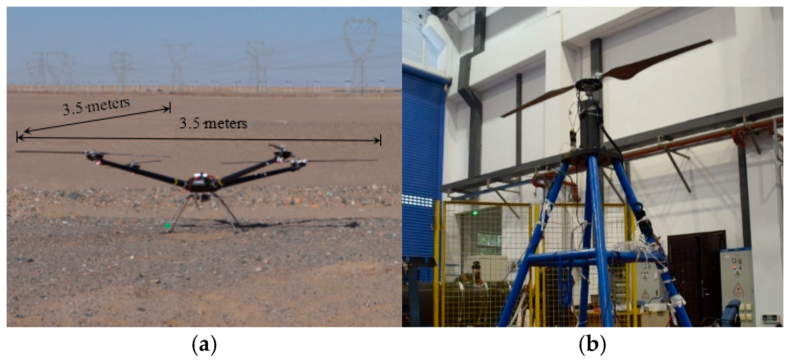
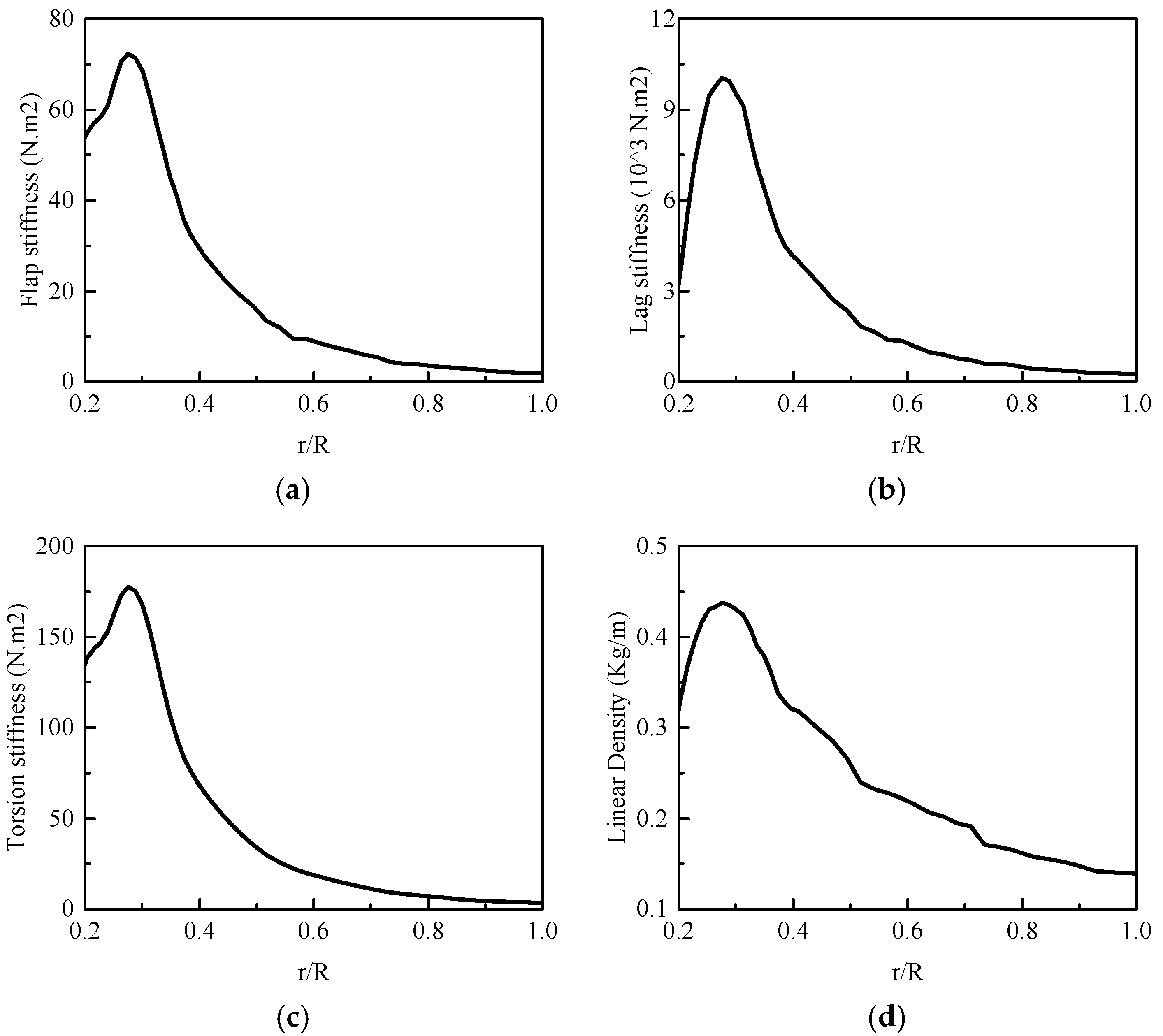
Figure 3a shows a 20 kg quad-copter UAV (Unmanned Aerial Vehicle), which was designed by CHRDI(China Helicopter Research Design Institute), whereas Figure 3b depicts the single rotor hover experiment of this UAV. The primary parameters are detailed in Table 1. The rotor blade profile is detailed in Figure 4a; the SD703 low Reynolds number airfoil is used in this rotor blade, and the rotor is equipped with only a lag-pitch coupling hinge (Figure 4b). The structural parameters of the blade are detailed in Figure 5, including flap stiffness, lag stiffness, torsion stiffness, and linear density.
Hub torque is measured using a six-axis force measurement system in the hover experiment, with a data acquisition frequency of 2 kHz. The motor used is the T-MOTOR 16,210, and rotor speed data are obtained from the motor’s feedback system at a sampling frequency of 20 Hz.
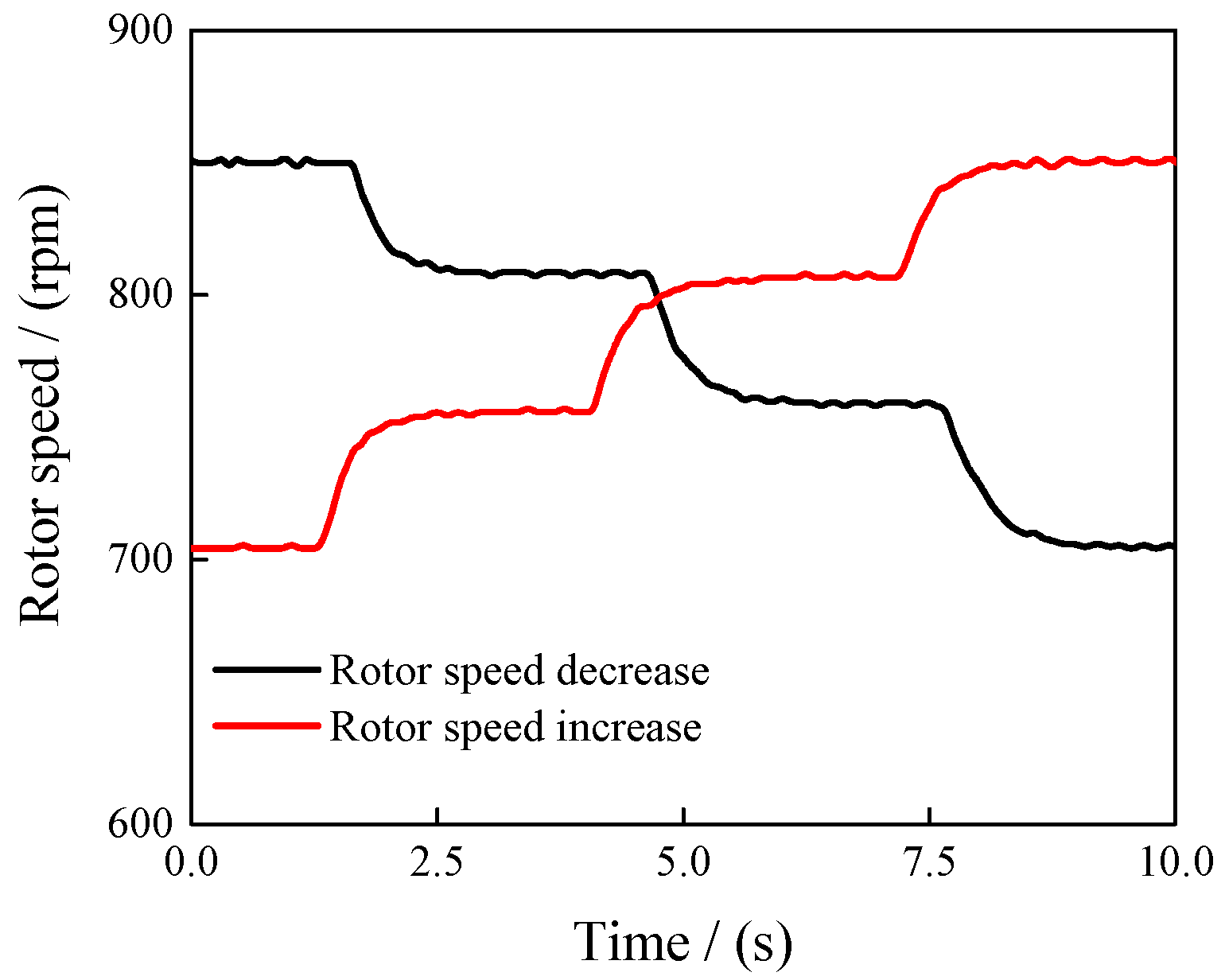
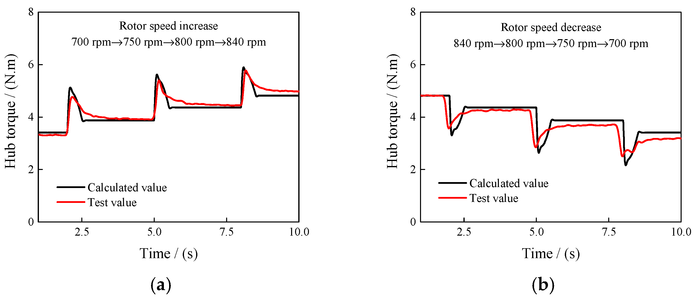
The hover experiment encompasses various rotor speeds ranging from 700 rpm to 850 rpm, including both constant speed and transient speed conditions. Table 2 compares the computed rotor torque with experimental data under various constant rotor speeds. The results show excellent agreement with the experimental data, with the maximum relative error in hub torque being less than 5%. Figure 6 presents the measured rotor speed data from transient experiments, including both increases and decreases in rotor speed, where the rotor speed ranges between 700 rpm and 840 rpm. The measured rotor speed fluctuates to a certain extent.
Figure 7 compares the computed transient rotor torque with experimental data. The rotor hub torque can be accurately predicted, especially as rotor speed increases, with a Mean Absolute Percentage Error (MAPE) of 3.6% compared to 5.6% during rotor speed decrease. Due to certain fluctuations in the measured rotor speed during the test, the test result curve of hub torque is not smooth. The results indicate that the hub torque overshoot is well captured, suggesting the effectiveness of the transient rotor dynamics model.

3. Analysis

The analyses of transient vibration loads are conducted using the XH-59A rotor. The main rotor parameters are provided in Table 3, with a 100% rotor speed of 345 rpm. Detailed rotor parameters can be found in [20]. Initially, transient vibration load analyses are performed for forward flight speeds of 300 km/h and 400 km/h, starting from a steady state. The trim conditions at both the start and end of these analyses are defined as follows: rotor thrust (T = 2250 kg), hub roll moment t ( M x = L o s T R ), and hub pitch moment ( M y = 0). The lift offset (Los), whose equation is as follows (Equation (9)), R means rotor radius. The lift offset is maintained at 0.27 for 300 km/h and at 0.315 for 400 km/h, consistent with the lift offset strategy employed by the XH-59A helicopter [21,22]. Subsequently, the entire transient process is segmented into partial steady states during rotor speed variations, maintaining the same trim goals for each segment. This approach allows for the comprehensive determination of rotor control throughout the transient process.
L o s = M x T · R
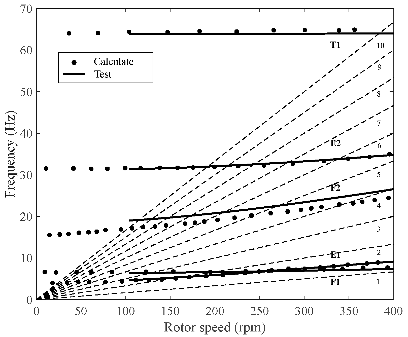
Figure 8 compares the computed rotor modal frequencies with the experimental data, where E represents lag modal, F represents flap modal, and T represents torsion modal. The dashed lines in the figure represent the frequency corresponding to the speed multiplication factor. The error between the calculation and test in the figure is less than 5%. The XH-59A rotor, a hingeless rotor, exhibits a 1st lag modal frequency of 7.12 Hz at 100% rotor speed and 6.94 Hz at 90% rotor speed according to the experimental data.

3.1. Hub Torque Overshoot

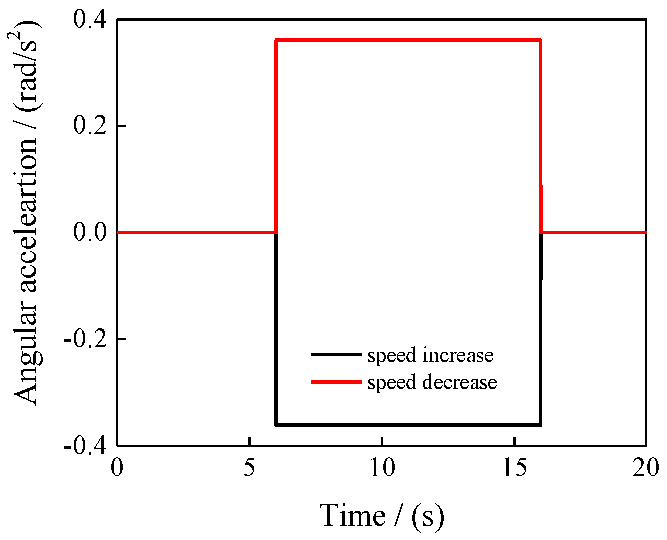
In this section, the impact of speed increase and decrease conditions during forward flight at two velocities (300 km/h and 400 km/h) is examined. The rotor speed variation ranges from 100% to 90% at 300 km/h and from 90% to 80% at 400 km/h. Figure 9 shows the angular acceleration curve under a linear change in rotor speed. The total duration is 20 s, with the rotor speed change occurring between 6 and 16 s. And the same angular acceleration curve in 400 km/h.
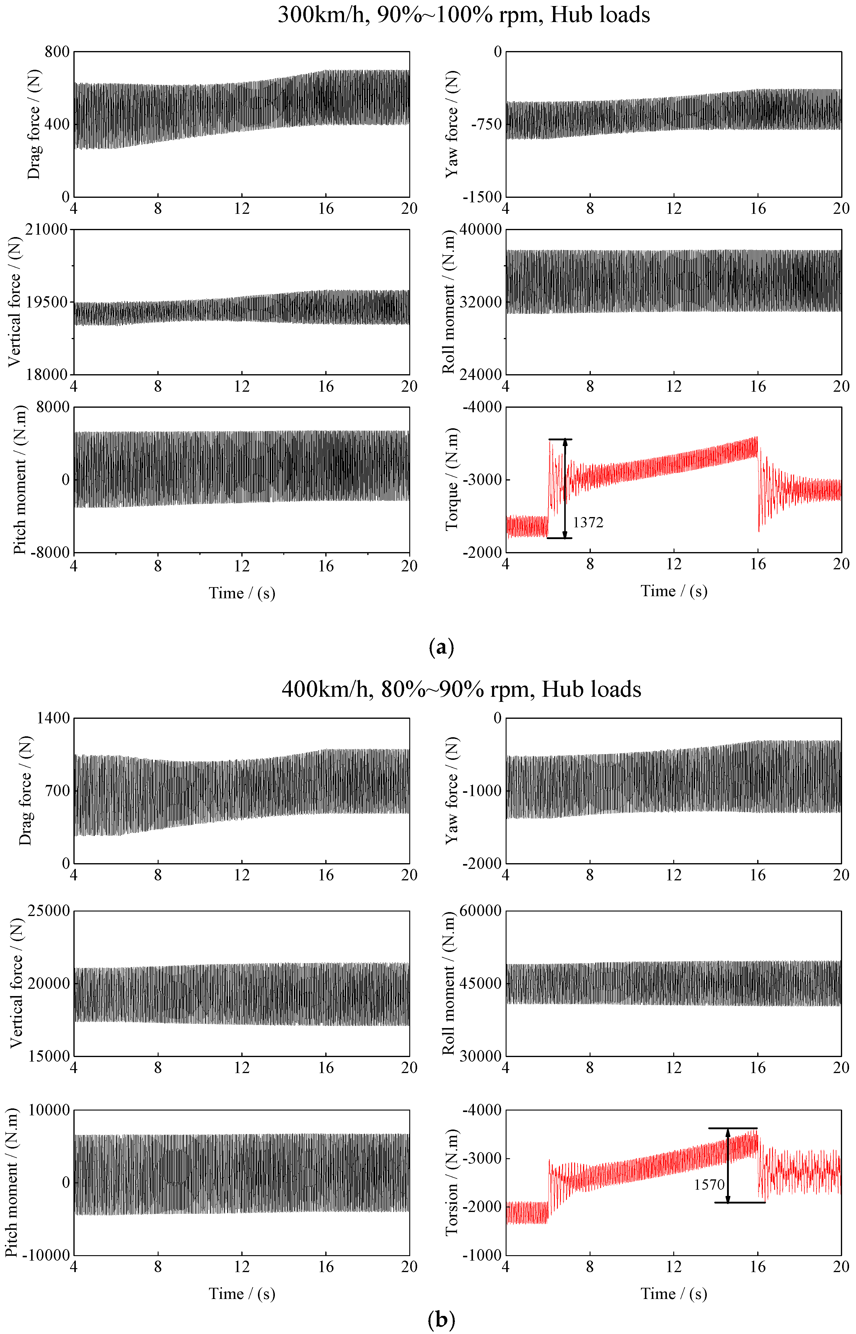
Figure 10 shows the computed hub loads results during the transient condition of rotor speed increase at two forward flight speeds. Throughout the entire transient process, the hub torque is most significantly influenced by rotor speed changes, while the forces and moments in other directions remain relatively stable.
At 300 km/h, the maximum hub torque transient overshoot occurs at the initiation of rotor speed changes. The torque transient overshoot (within 0.2 s) is around 1372 N·m, which is approximately 58.3% of the mean pre-start hub torque. At 400 km/h, the maximum hub torque transient overshoot occurs at the end of the rotor speed changes. The torque transient overshoot (within 0.5 s) is around 1570 N·m, which is approximately 57.4% of the mean afterward hub torque.
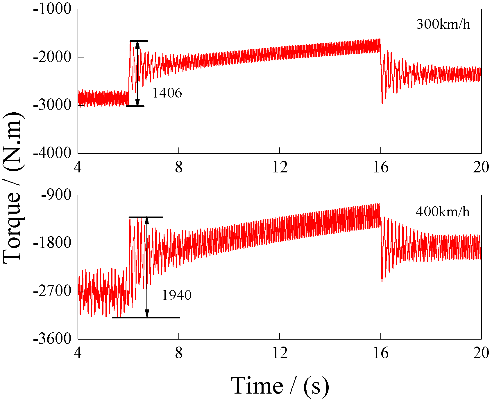
Figure 11 shows the computed hub torque results during rotor speed decrease at two forward flight speeds. An obvious overshoot in hub torque occurs at both the start and end of the rotor speed change, regardless of whether the rotor speed is increasing or decreasing. The hub torque gradually converges and stabilizes over time. This behavior is attributed to the impulsive inertial moment generated by angular acceleration during the start and end phases. Throughout the entire transient process in 300 km/h, the maximum hub torque transient overshoot (within 0.2 s) is around 1406 N·m in 300 km/h, and 1940 N·m in 400 km/h.
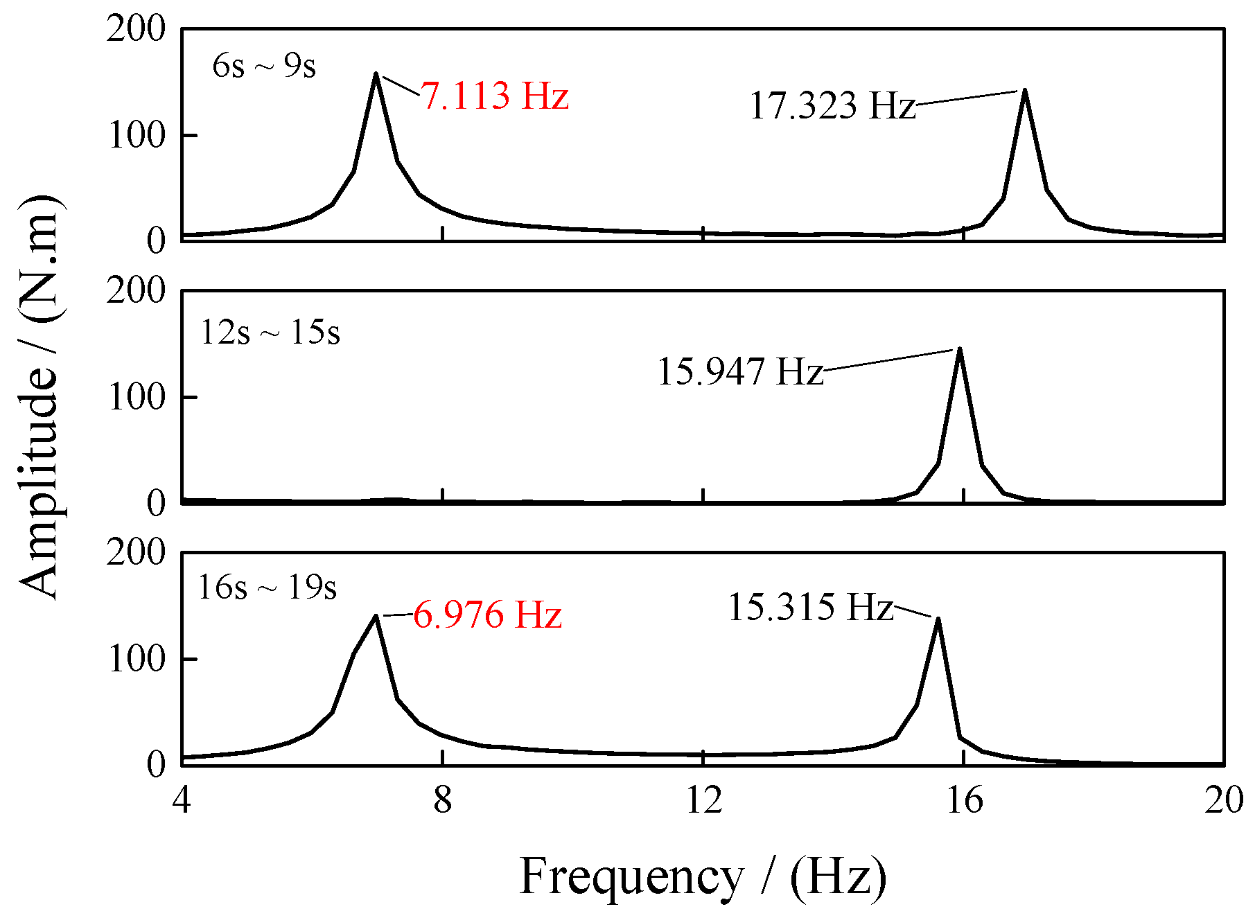
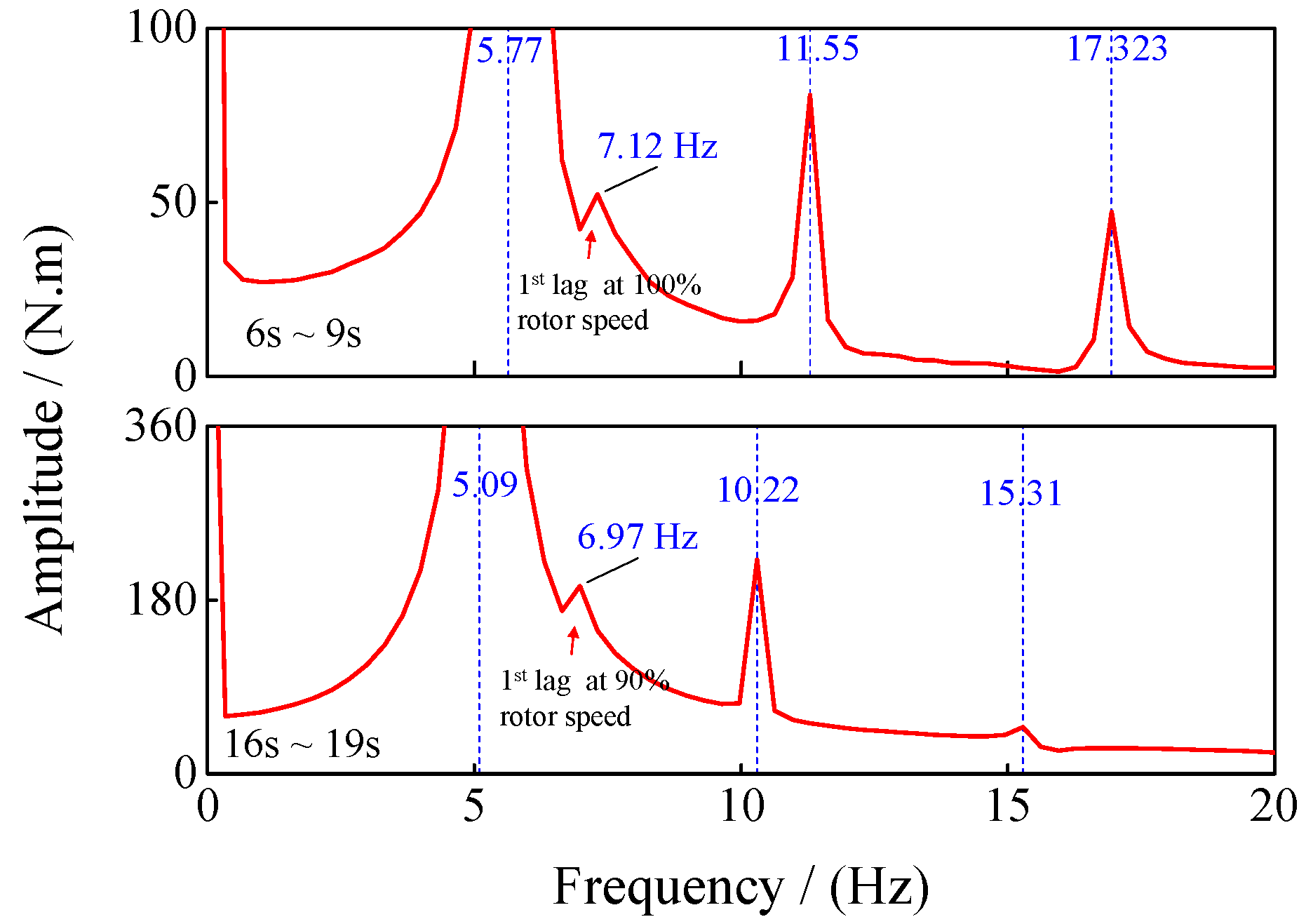
Figure 12 presents the FFT (Fast Fourier Transform) frequency spectrum results during three time intervals: 6~9 s, 12~15 s, and 16~19 s, as the rotor speed decreases during forward flight at 300 km/h. The frequency resolution is 100 Hz. The analysis reveals that low-frequency amplitudes of 7.113 Hz are observed in the initial periods, while low-frequency amplitudes of 6.976 Hz are present in the later periods. The hub torque main frequency is three times the rotor speed frequency, which XH-59A rotor has three blades, but it is noted that 7.113 Hz corresponds to the 1st lag frequency of the blade at 100% rotor speed, whereas 6.976 Hz corresponds to the 1st lag frequency of the blade at 90% rotor speed, as shown in Figure 8. Blade lag bending moment is the primary contributor to rotor hub torque. Consequently, particular attention is drawn to the blade root lag bending moment, as illustrated in Figure 13. The FFT frequency spectrum analysis between 6~9 s and 16~19 s reveals that the blue dotted line values exhibit a multiple relationship with the rotor speed. Notably, significant frequency amplitudes at 7.12 Hz and 6.97 Hz are observed, corresponding to the 1st lag frequency at 100% and 90% of the rotor speed. This indicates that the inertial moment in hub torque is primarily caused by the blade root lag bending moment at the 1st lag frequency during the start and end phases due to impulsive angular acceleration signals. Furthermore, these effects cannot be filtered out by the rotor hub system.

3.2. Parameter Influence

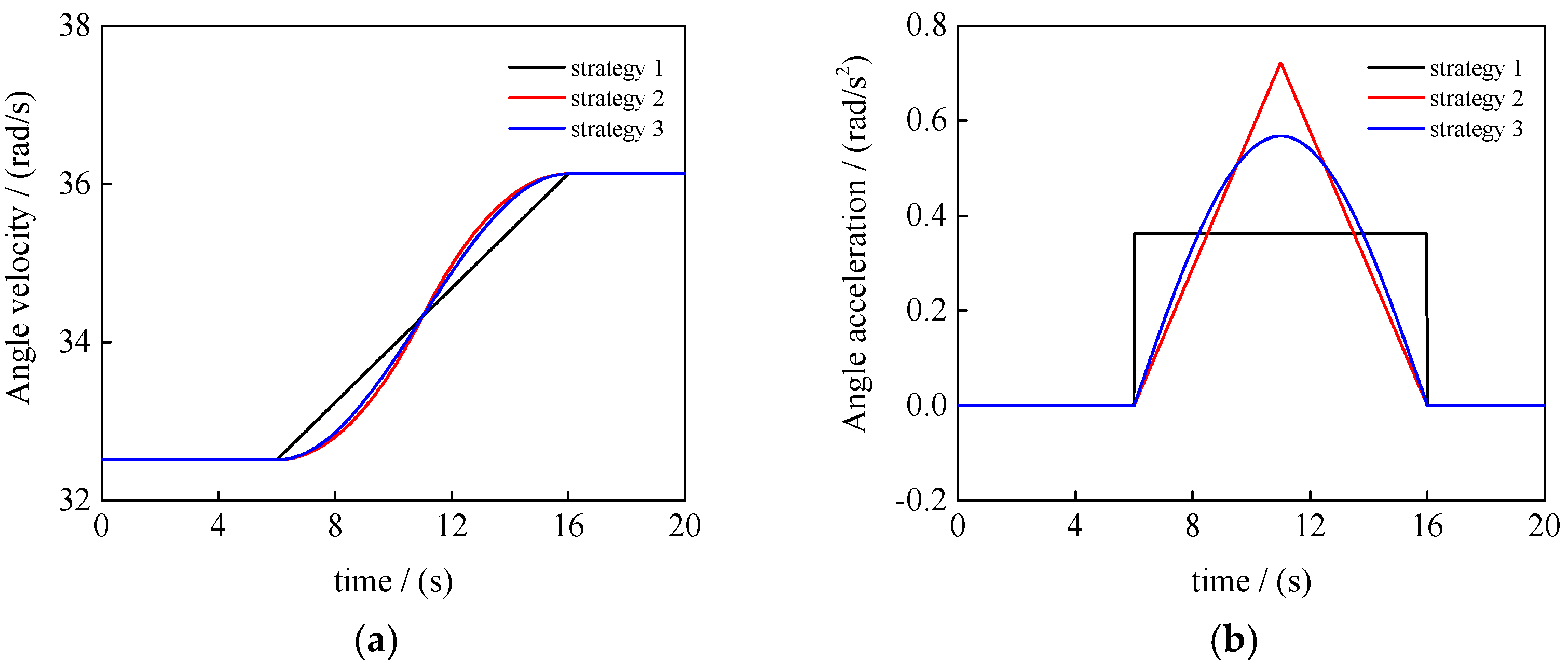
The aforementioned analyses demonstrate that during the transient process of linearly changing rotor speed, impulsive angular acceleration can induce substantial hub torque. This phenomenon poses unfavorable effects on the rotor/drive/engine system. To mitigate this issue, it is crucial to ensure that the rotor angular acceleration during the transient phase is as smooth as possible. In order to study the effect of rotor speed variation on rotor dynamic loads, this section evaluates three distinct transient strategies for a 90% to 100% rotor speed increase during forward flight at 300 km/h (Figure 14). The different rotor speeds are as follows, where Ω 0 represents the initial rotor speed, Ω 1 represents the final rotor speed, t represents time, t e represents the end time, and t s represents the start time.
Ω = Ω 0 , 0 < t 6 Ω 1 Ω 0 10 ( t 6 ) + Ω 0 6 < t 16 Ω 1 16 < t 20 Ω = Ω 0 t < 6 Ω 0 + Ω 1 Ω 0 2 cos ( t 6 10 π + π ) + 1 6 t 16 Ω 1 16 t Ω = Ω 0 0 t < 6 Ω 0 + Ω 1 Ω 0 0.5 ( t e t s ) 2 ( t 6 ) 2 6 t < 11 Ω 1 + Ω 0 Ω 1 0.5 ( t e t s ) 2 ( 16 t ) 2 11 t < 16 Ω 1 16 t 20
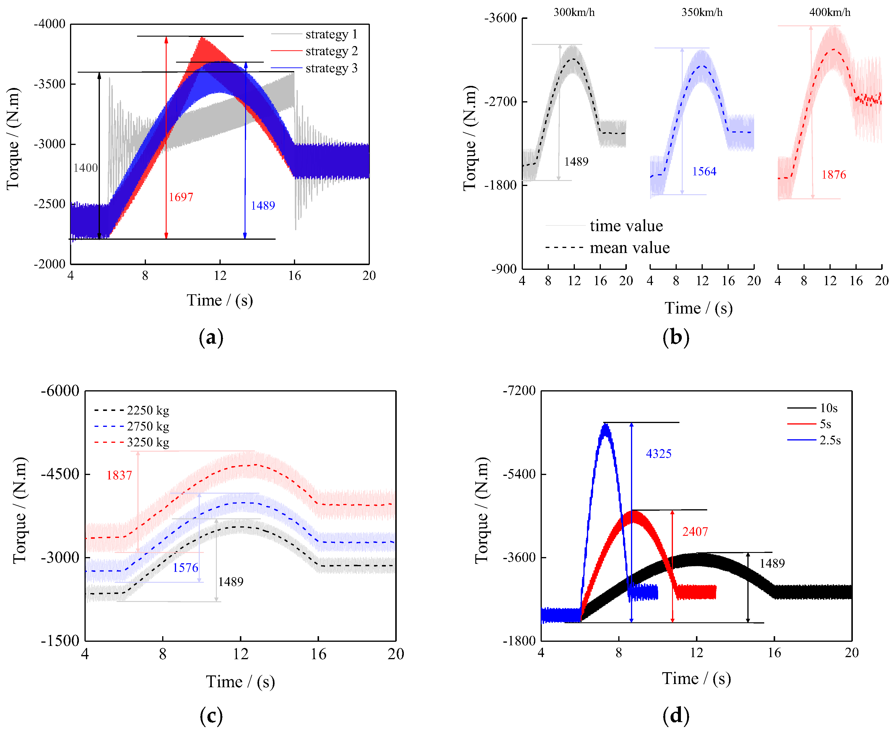
Figure 15a shows the rotor hub torque results under different transient strategies. It is indicated that the characteristics of hub torque closely resemble those of angular acceleration under transient conditions. In three strategies, the total overshoots are 1400 N·m, 1697 N·m, and 1489 N·m throughout the entire transient process. There are approximately 59.5%, 72.1%, and 63.3% of the mean pre-start hub torque. But in strategies 2 and 3, the hub torque transitions more smoothly, and impulsive loads are eliminated. However, under strategy 2, there is a noticeable turning point in the middle of the time period, similar to the behavior observed in angular acceleration. This confirms that impulsive angular acceleration can lead to significant hub torque fluctuations. Among the three strategies, strategy 3 exhibits the smoothest and most stable hub torque. It is validated that the design of angular acceleration transient strategies should be as smooth as possible to minimize impulsive vibration loads. Figure 15a also shows that hub torque overshoots regardless of the angular acceleration transient strategy employed.
In strategy 3, Figure 15b presents the computed hub torque results at various forward flight speeds, while maintaining constant rotor speed, transient process, and rotor thrust (T = 2250 kg) within the same range of 80~90%. The dashed line represents the time domain average of dynamic loads. The total overshoots are 1876 N·m, 1564 N·m, and 1489 N·m throughout the entire transient process in three flight speed conditions. There are approximately 73.5%, 81.9%, and 100.1% of the mean pre-start hub torque. The results indicate that it has a minor increase in the overshoot of rotor hub torque during the transient process. The torque overshoot during the transient process is primarily influenced by the inertial forces of the rotor system, which are mainly determined by angular acceleration, rather than forward flight speed. But in 400 km/h conditions, the total overshoot obviously increases, because the blade drag obviously increases at high flight speed.
In strategy 3, Figure 15d presents the computed hub torque during the 90% to 100% rotor speed transient process under three different transient times at a forward flight speed of 300 km/h. The total overshoots are 4325 N·m, 2407 N·m, and 1489 N·m throughout the entire transient process in three transient times. There are approximately 187.9%, 104.6%, and 63.3% of the mean pre-start hub torque. The findings reveal that shorter transient times result in greater total overshoots of rotor hub torque throughout the entire transient process. This phenomenon occurs because the transient time directly influences the angular acceleration and the transient inertial moment in the hub torque. Consequently, to minimize the overshoot caused by variable rotor speed, it is essential to extend the transient process time as much as possible, thereby ensuring a smoother transition in rotor hub torque.
Table 4 shows the comparison of the results of different strategies. The values of overshoot/time reflect the rate of change in overshoot throughout the entire transient process. The rotor thrust and flight speed have little influence on the rate of change in overshoot, and the rotor angular acceleration and transient times have a significant influence. The value of overshoot/time can be reduced by 98.6% at most in three angular acceleration strategies, and it can be reduced by 92.7% at most in three transient times. In the design of the rotor variable speed strategy, the change time should be prolonged and the angular acceleration should be reduced as much as possible.

3.3. Torque Reduction

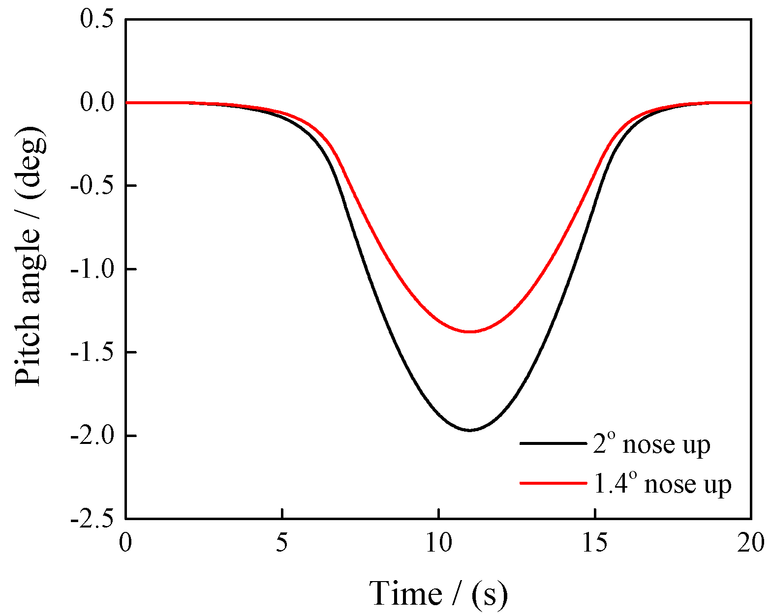
Changing the rotor attitude or rotor control can influence the hub load during forward flight [22]. Based on this principle, adjusting the rotor attitude or control parameters can mitigate hub torque total overshoot during transient processes, thereby achieving smoother transient flight. Figure 16 shows two strategies for varying the rotor pitch angle (negative values indicate nose up) during the 90% to 100% rotor speed transient process at 300 km/h forward flight, where the transient rotor speed is strategy 3.
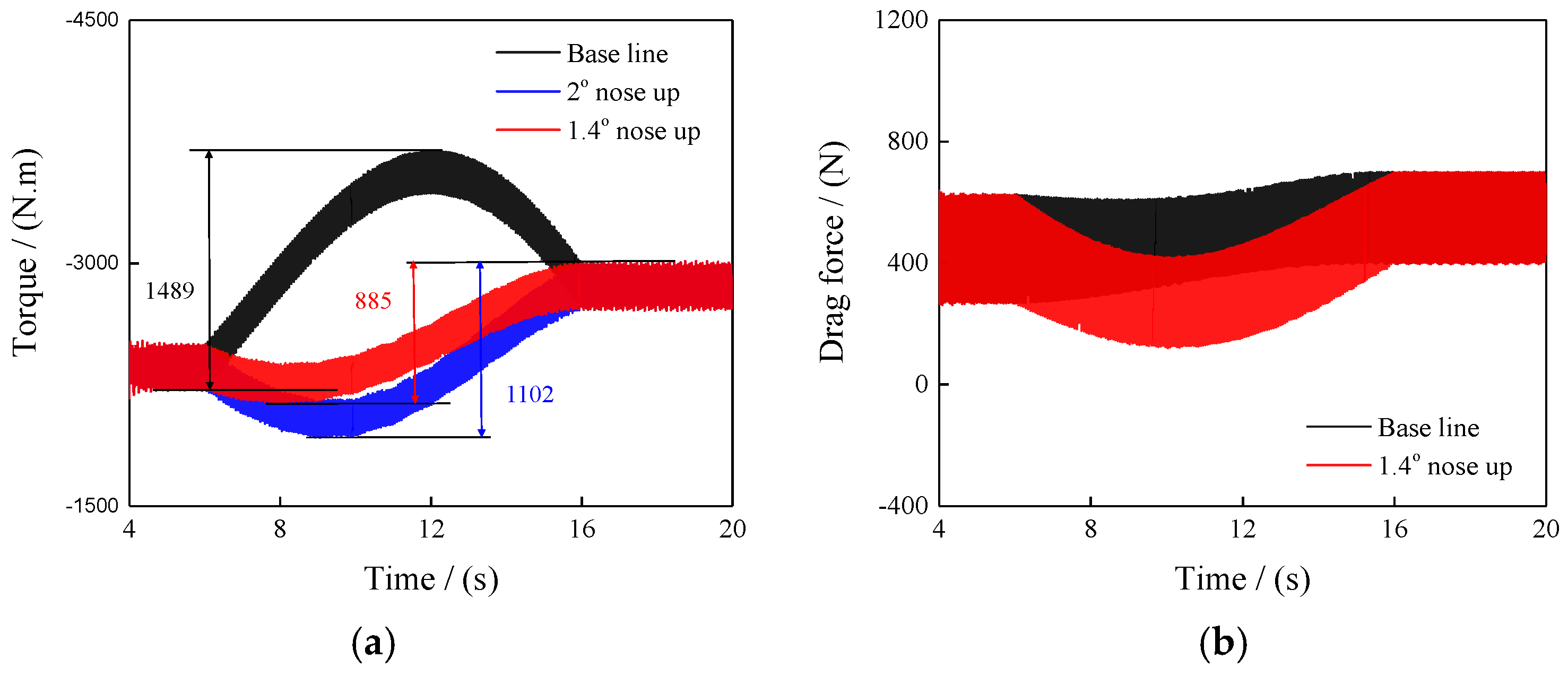
Figure 17a shows the computed results of hub torque under these two different transient strategies. The total overshoots are 1489 N·m 1102 N·m, and 885 N·m throughout the entire transient process in three strategies. There are approximately 63.3%, 46.8%, and 37.6% of the mean pre-start hub torque. The findings indicate that an appropriate increase in the rotor’s nose-up pitch angle during variable speed transients can effectively reduce total torque overshoot, with a 1.4 degree nose-up pitch angle appearing to be particularly effective. Although during the transient state, rotor thrust, roll moment, and pitch moment are based on the trim control, it is important to note that such a nose-up pitch angle may also cause overshoot in hub drag force during the transient state, as shown in Figure 17b, which requires careful consideration.
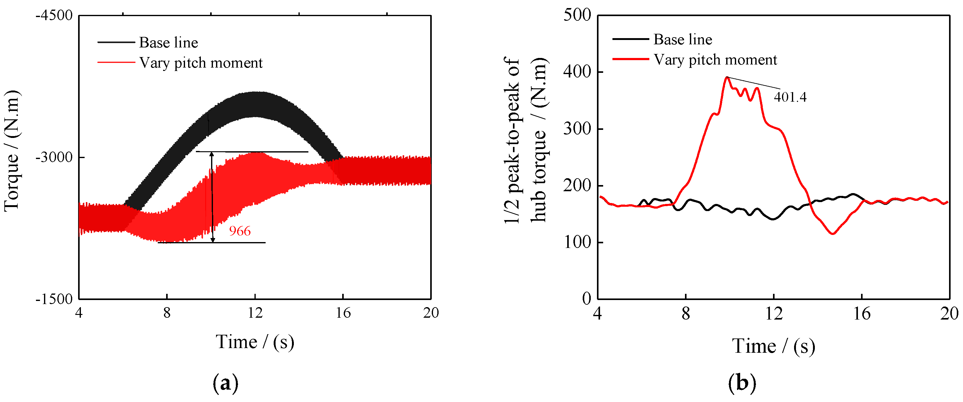
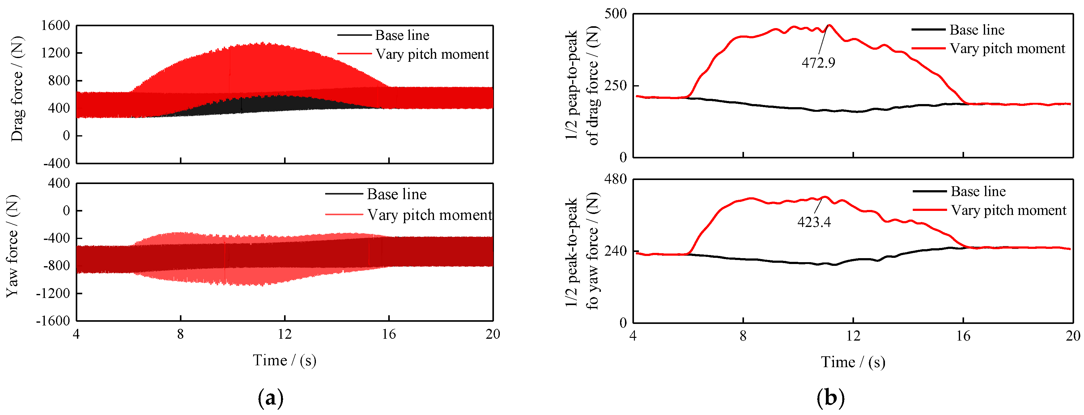
Changing the rotor control can significantly influence the hub load during forward flight. Taking the hub pitch moment My as an example, the trim objective for pitching moment is assumed to fluctuate during the transient, which is expressed in Equation (11), for example. Figure 18a illustrates the computed results of hub torque under a strategy of varying hub pitch moment during the 90% to 100% rotor speed transient process at 300 km/h forward flight. The total overshoot is 996 N·m throughout the entire transient process in the varying pitch moment strategy. It is approximately 43.2% of the mean pre-start steady-state hub torque. And the results are both lower than the base results (1489 N and 63.3% in Figure 17a). The results indicate that appropriately adjusting the hub pitch moment during variable speed transients can reduce total torque overshoot, but the 1/2 peak-to-peak of hub torque significantly increases in an 8~14 s interval (Figure 18b). The maximum 1/2 peak-to-peak of hub torque is 401.4 N·m. It is approximately 246% of the 1/2 peak-to-peak of the hub torque in the steady state. Figure 19 shows that the hub drag force and yaw force also increase (Figure 19a), the maximum 1/2 peak-to-peak of drag force is 472.9 N (Figure 19b). It is approximately 227% of the 1/2 peak-to-peak of the drag force in the steady state. The maximum 1/2 peak-to-peak of yaw force is 423.4 N. It is approximately 185% of the 1/2 peak-to-peak of the yaw force in the steady state.
Modifying the hub pitch moment during the transient state incurs additional costs and does not appear to be an effective torque reduction strategy. Moreover, there are various control strategies for reducing rotor loads during maneuvering states to address the torque overshoot problem, which need further research and analysis.
M y = 27600 0 t < 6 sin ( ( t 6 ) π / 10 ) 6 t 16 0 16 t

4. Conclusions

In this paper, the transient rotor system dynamics model and transient blade load calculation model are utilized to investigate the characteristics of transient vibration loads, different from the traditional steady-state rotor dynamics analysis based on fixed rotor speed, leading to the following conclusions:
(1)
During transient processes, the rotor hub torque is significantly affected, whereas other hub forces and moments remain largely unchanged. Notably, there is a pronounced overshoot in rotor hub torque at both the start and end of the rotor speed change, whether the rotor speed is accelerated or decelerated. The maximum total overshoot is 1940 N·m within 0.2 s at 400 km/h rotor speed decrease transient process. Special attention should be given to the dynamic behavior of the rotor and transmission system.
(2)
The characteristics of rotor hub torque are closely associated with the transient process of rotor angular acceleration. A linear transient process of angular acceleration results in significant impulsive effects at the start and end of the rotor speed change. The maximum value of overshoot/time is 17,500 N·m·s−1. To minimize these effects, it is essential to ensure that the rotor angular acceleration is as smooth as possible, thereby achieving a smoother variation in rotor hub torque.
(3)
The overshoot of rotor hub torque during the transient process is primarily influenced by angular acceleration, whereas flight speed and rotor thrust have minimal impact. The value of overshoot/time can be reduced by 98.6% at most in three angular acceleration strategies, and it can be reduced by 92.7% at most in three transient times.
(4)
Adjusting the rotor pitch attitude and control mechanisms can effectively mitigate hub torque overshoot. Adjusting the rotor pitch attitude during the transient state appears to be an effective strategy for reducing hub torque. Altering the hub pitch moment during transient states incurs additional costs and does not appear to be an effective torque reduction strategy; the 1/2 peak-to-peak of hub torque, drag force, and yaw force would increase by around 2 times. Future research should focus on analyzing load reduction techniques during maneuvering.

Author Contributions

Methodology, J.H.; Validation, Y.C.; Writing—original draft, Z.Y.; Writing—review & editing, Z.Y. and C.L. All authors have read and agreed to the published version of the manuscript.

Funding

This research received no external funding.

Data Availability Statement

Due to work confidentiality, it is not convenient to publicly provide the data.

Conflicts of Interest

The authors declare no conflicts of interest.

References

  1. Deng, J.H. Key technologies and development for high-speed helicopters. Acta Aeronaut. Et Astronsutica Sin. 2024, 45, 1–20. [Google Scholar]
  2. Deng, J.H. Technical status and development of electric vertical take-off and landing aircraft. Acta Aeronaut. Et Astronsutica Sin. 2024, 45, 47–69. [Google Scholar]
  3. Schuster, D. S-97 Raider Propulsor Flight Loads and Validation. In Proceedings of the 79th Annual Vertical Flight Society Forum and Technology Display, West Palm Beach, FL, USA, 16–18 May 2023. [Google Scholar]
  4. Muscarello, V.; Quaranta, G. Optimal Tiltrotor Blade Twist to Extend Whirl-Flutter Stability Boundaries. In Proceedings of the 62nd American Institute of Aeronautics and Astronautics Science and Technology Forum and Exposition, Harbor, MD, USA, 23–27 January 2023. [Google Scholar]
  5. Lu, Y.L.; Cao, D.; Qu, Q.; Zu, J.K. Active Disturbance Rejection Control for a Compound Helicopter during Transitional Period. In Proceedings of the 2023 China Automation Congress(CAC), Chongqing, China, 17–19 November 2023. [Google Scholar]
  6. Littell, J.; Putnam, J. A Summary of Test Results from a NASA Lift + Cruise eVTOL Crash Test. In Proceedings of the 79th Annual Vertical Flight Society Forum and Technology Display, West Palm Beach, FL, USA, 16–18 May 2023. [Google Scholar]
  7. Graham, M.B.D. Performance and Loads of Variable Tip Speed Rotorcraft at High Advance Ratios. Ph.D. Thesis, University of Maryland, College Park, MD, USA, 2015. [Google Scholar]
  8. Weiss, F.; Kessler, C. Drivetrain Influence on the Blade Loads of Hingeless Helicopter Rotors. In Proceedings of the 79th Annual Vertical Flight Society Forum and Technology Display, Philadelphia, PA, USA, 13–16 May 2019. [Google Scholar]
  9. Wang, X.; Bauknech, A.; Maurya, S.; Chopra, I. Slowed Hingeless Rotor Wind Tunnel Tests and Validation at High Advance Ratios. J. Aircr. 2020, 58, 1–14. [Google Scholar] [CrossRef]
  10. Han, D.; Wang, H.W.; Gao, Z. Aeroelastic analysis of a shipboard helicopter rotor with ship motions during engagement and disengagement operations. Aerosp. Sci. Technol. 2012, 16, 1–9. [Google Scholar] [CrossRef]
  11. Yu, Z.; Zhuo, Y.; Song, B. Aeroelastic modeling and load analysis of a variable speed rotor in high advance ratio. J. Vib. Shock 2021, 40, 17–22. [Google Scholar]
  12. Huang, J.; Yu, Z.; Cheng, Y. Transient dynamic modeling and load characteristic analysis of variable speed rotor. China Sci. Technol. Inf. 2023, 22, 41–45. [Google Scholar]
  13. Jinggen, Z.; Lorber, P.F.; Brigley, M. S-97 RAIDER Empennage Loads and Vibrations: Analysis, Correlation and Understanding. In Proceedings of the 61st American Institute of Aeronautics and Astronautics Science and Technology Forum and Exposition, San Diego, CA, USA, 3–7 January 2022. [Google Scholar]
  14. Öhrle, C.; Frey, F.; Thiemeier, J.; Keßler, M.; Krämer, E.; Embacher, M.; Cranga, P.; Eglin, P. Compound Helicopter X-3 in High-Speed Flight: Correlation of Simulation and Flight Test. In Proceedings of the 75th Annual Vertical Flight Society Forum and Technology Display, Philadelphia, PA, USA, 13–16 May 2019. [Google Scholar]
  15. Malpica, C.; Withrow-Maser, S. Handling Qualities Analysis of Blade Pitch and Rotor Speed Controlled eVTOL Quadrotor Concepts for Urban Air Mobility. In Proceedings of the VFS International Powered Lift Conference, San Jose, CA, USA, 21–23 January 2020. [Google Scholar]
  16. Brenner, F.; Foraste, G.L.; Goericke, J.; Hasbun, M. Comprehensive Simulation for eVTOL Air-craft-Diagnosing Coupled Airframe Propulsion Dynamic Instabilities. In Proceedings of the 78th Annual Vertical Flight Society Forum and Technology Display, Fort Worth, TX, USA, 10–12 May 2022. [Google Scholar]
  17. Cho, C.; Rahn, C.D.; Smith, E.; Singh, P. Active Vibration Damping and Harmonic Vibration Reduction in an eVTOL Aircraft Model Using Electric Rotor Torque. In Proceedings of the 80th Annual Vertical Flight Society Forum and Technology Display, Montreal, QC, Canada, 7–9 May 2024. [Google Scholar]
  18. Yu, Z.; Huang, J.; Jiang, Q.; Fan, F.; Huang, S. Rotor Dynamic Loads Characteristic Analysis With Blade Tip Twist Distribution. In Proceedings of the 34th Congress of the International Council of the Aeronautical Sciences, Florence, Italy, 9–13 September 2024. [Google Scholar]
  19. Yu, D.; Sirohi, J.; Mortimer, P. Extraction of a Dynamic Inflow Model from Wake Measurements on a Hovering Rotor. In Proceedings of the 80th Annual Vertical Flight Society Forum and Technology Display, Montreal, QC, Canada, 7–9 May 2024. [Google Scholar]
  20. Felker, F.F. Performance and Loads Data form a wind Tunnel Test of a Full-Scale, Coaxial, Hingeless Rotor Helicopter; Report No. TM81329; NASA: Washington, DC, USA, 1981.
  21. Ferguson, K.M. Towards a Better Understanding of the Flight Mechanics of Compound Helicopter Configurations. Ph.D. Thesis, University of Glasgow, Glasgow, UK, 2015. [Google Scholar]
  22. Eller, E. X2TM Load Alleviating Controls. In Proceedings of the 68th American Helicopter Society International Annual Forum, Fort Worth, TX, USA, 1–4 May 2012; p. 1578. [Google Scholar]
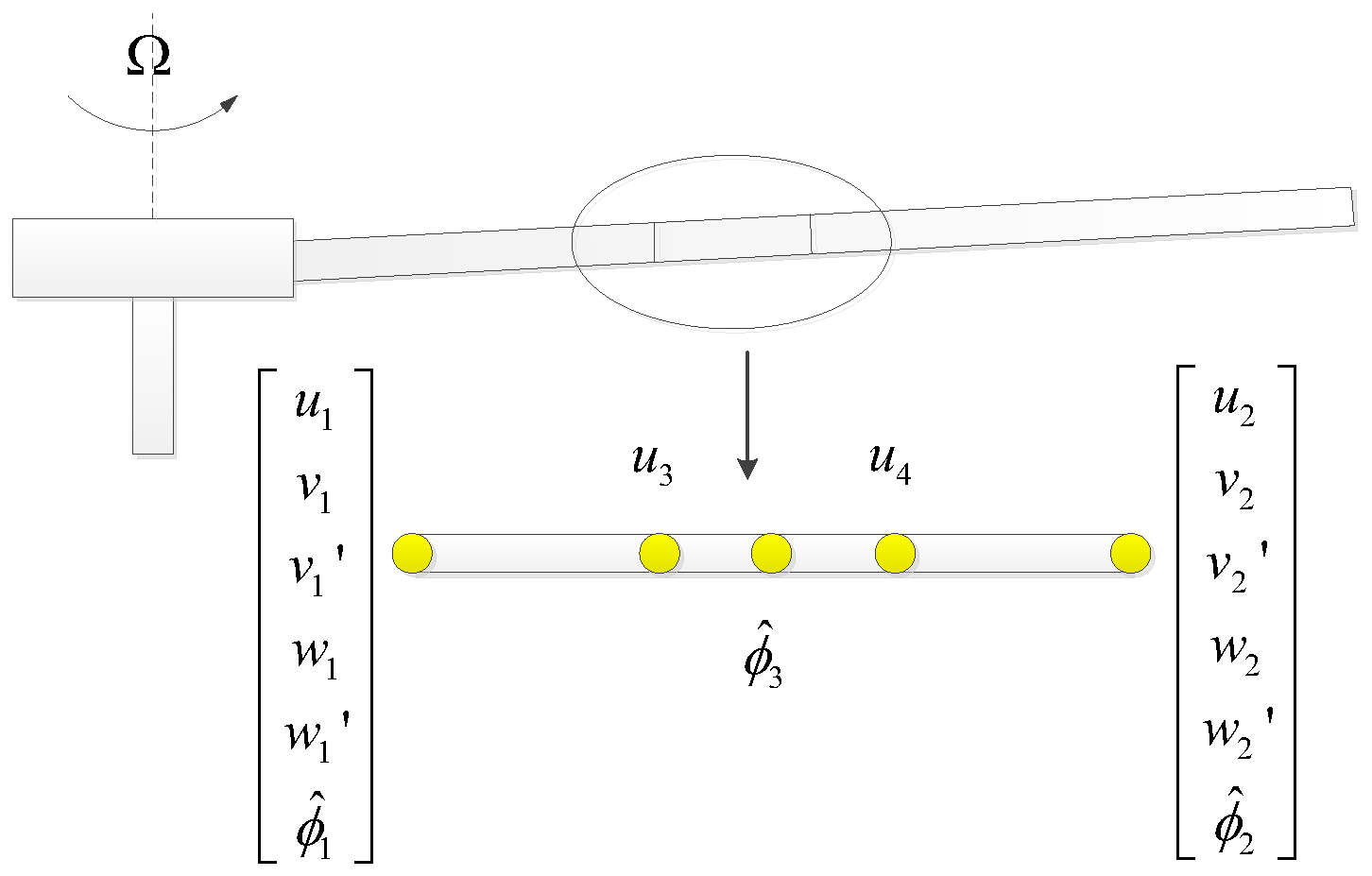
Figure 1. Finite element unit schematic diagram.
Applsci 15 10493 g001
Figure 2. Flowchart of response solving.
Applsci 15 10493 g002
Figure 3. (a) 20kg quad-copter UAV, (b) Single rotor hover experiment.
Applsci 15 10493 g003
Figure 4. (a) Blade profile, (b) Lag-pitch coupling hinge.
Applsci 15 10493 g004
Figure 5. (a) Flap stiffness, (b) Lag stiffness, (c) Torsion stiffness, (d) Linear density.
Applsci 15 10493 g005
Figure 6. Measured rotor speed.
Applsci 15 10493 g006
Figure 7. (a) Hub torque in rotor speed increase, (b) Hub torque in rotor speed decrease.
Applsci 15 10493 g007
Figure 8. Rotor resonance.
Applsci 15 10493 g008
Figure 9. Rotor angular acceleration.
Applsci 15 10493 g009
Figure 10. (a) Hub loads in 300 km/h, (b) Hub loads in 400 km/h.
Applsci 15 10493 g010
Figure 11. Hub torque in rotor speed decreases.
Applsci 15 10493 g011
Figure 12. Hub torque frequency spectrum at 300 km/h.
Applsci 15 10493 g012
Figure 13. Blade root lag bending moment frequency spectrum at 300 km/h.
Applsci 15 10493 g013
Figure 14. (a) Rotor speed, (b) Angular acceleration.
Applsci 15 10493 g014
Figure 15. (a) Hub torque, (b) Hub torque, (c) Hub torque, (d) Hub torque.
Applsci 15 10493 g015
Figure 16. Rotor pitch angle variation.
Applsci 15 10493 g016
Figure 17. (a) Hub torque, (b) Hub drag force.
Applsci 15 10493 g017
Figure 18. (a) Hub torque, (b) 1/2 peak-to-peak of hub torque.
Applsci 15 10493 g018
Figure 19. (a) Hub force, (b) 1/2 peak-to-peak of hub force.
Applsci 15 10493 g019
Table 1. Main rotor parameters.
ParameterValues
Rotor radius (m)0.829
Number of blades2
Extension of lag hinge (mm)100
Mass (g)250
Rotor solidity (σ)0.049
Blade installation angle (o)6.5
Blade twist angle (o)−10.2
Table 2. Comparison of computed hub torque and experimental data.
Rotor Speed (rpm)Test Value (N·m)Calculated Value (N·m)Error
7003.313.15−4.8%
7453.673.55−3.3%
7543.83.63−4.5%
7753.953.83−3.0%
8054.314.12−4.4%
8474.754.54−4.4%
Table 3. XH-59A rotor parameters.
ParametersValues
Rotor radius (m)5.4864
Number of blades2 × 3
Taper ratio2:1
Tip chord0.286
Rotor space (m)0.762
Pre-twist (deg)3
Rotor solidity0.1267
Rotor speed (rad/s)36.11
Table 4. Comparison of Results.
StrategyThe Total Overshoot
(N·m)
Time to Total Overshoot (s)Overshoot/Time (N·m·s−1)
Angular accelerationStrategy 114000.0817500
Strategy 216975.02338.04
Strategy 314896.21239.77
Flight speed300 km/h14895.84254.97
350 km/h15646.04258.94
400 km/h18766.65282.10
Rotor thrust2250 kg14895.79257.17
2750 kg15766.24252.56
3250 kg18376.51282.18
Transient times10 s14896.09244.50
5 s24072.77868.95
2.5 s43251.293352.71
Disclaimer/Publisher’s Note: The statements, opinions and data contained in all publications are solely those of the individual author(s) and contributor(s) and not of MDPI and/or the editor(s). MDPI and/or the editor(s) disclaim responsibility for any injury to people or property resulting from any ideas, methods, instructions or products referred to in the content.