Article

Characteristics of Mining-Induced Stress Rotation Due to Unloading in Deep Roadway Excavation and Surrounding Rock Control Countermeasures

School of Resources and Safety Engineering, Central South University, Changsha 410083, China
*
Author to whom correspondence should be addressed.
Appl. Sci. 2025, 15(18), 9950; https://doi.org/10.3390/app15189950
Submission received: 20 August 2025 / Revised: 8 September 2025 / Accepted: 9 September 2025 / Published: 11 September 2025
(This article belongs to the Topic Failure Characteristics of Deep Rocks, Volume II)

Abstract

As metal mines advance into deep mining, the increase in tectonic stress and horizontal stress leads to a higher degree of joint and fissure development in roadway surrounding rocks, along with a significant rise in both the fragmentation degree of the rock mass and the support cost. This paper adopts field monitoring and numerical simulation methods to analyze the characteristics of mining-induced stress rotation after unloading due to deep roadway excavation in the Jinchuan mining area, and proposes corresponding surrounding rock control countermeasures and optimized schemes for the original support. The research results show that after the unloading caused by the excavation of deep roadway surrounding rock, the magnitudes and directions of the maximum, intermediate, and minimum principal stresses all exhibit a trend of slow change, followed by drastic change, and finally gradual stabilization. When the roadway advances to 4 m in front of the monitor section, the adjustment of the magnitude of principal stress of the surrounding rock is the most drastic. Moreover, as the working face moves away from the monitor section, the principal stress gradually stabilizes and becomes lower than the initial stress value. When the roadway advances to 6 m in front of the monitor section, the adjustment of the direction of the principal stress of the surrounding rock is the most drastic. The rotation angle of the maximum principal stress shows a trend of first increasing and then decreasing with the increase in the excavation step, while the rotation angles of the intermediate and minimum principal stresses show a trend of first decreasing and then increasing as the excavation step increases. Based on the spatial distribution characteristics of joints and fissures in the roadway surrounding rock, the sensitive area for the rotation of mining-induced stress direction is defined. By changing the advancing direction of the roadway, the rotation trajectory of the principal stress can be deviated from the sensitive area, thereby improving the self-stabilization ability of the roadway surrounding rock. It is proposed that asymmetric coupling support be adopted to reinforce the positions where the principal stress rotation of the rock mass around the anchorage is severe, which can effectively reduce the range of the plastic zone in the roadway surrounding rock. The research results provide new ideas for the surrounding rock control of deep roadways, as well as a theoretical basis for the design and optimization of roadway support parameters in similar mines.

1. Introduction

As metal mines gradually move into deep mining, the increase in tectonic stress and the enhancement of mining disturbance effects have led to a higher degree of development of joints and fissures in the surrounding rock of deep roadways, as well as an aggravation of rock mass fragmentation [1,2,3,4]. Affected by mining disturbance effects, engineering disasters such as floor heave in deep roadways [5], large deformation of surrounding rock on both sides [6], roof subsidence [7], and failure of support structures [8] occur frequently, which seriously affect the tunneling efficiency of deep mines and the safe recovery of resources [9,10]. Therefore, existing supports for deep roadways are not enough to control the impact of mining-induced stress rotation on the damage and failure of the surrounding rock, so it is necessary to optimize the support scheme according to the characteristics of mining-induced stress rotation of the surrounding rock [11].
After the excavation and unloading of deep roadways, the initial in situ stress is redistributed, which is mainly manifested in the changes in the magnitude and the rotation of the direction of the principal stress [12]. Kaiser et al. [13,14] hold that the change in the direction of the principal stress in the roadway surrounding rock has a significant impact on the failure mode of the rock mass and the fracture propagation path. Eberhardt et al. [15] argue that during the excavation of underground space engineering, the rotation of principal stresses plays a decisive role in the propagation path of fractures. Therefore, the change in the magnitude of the principal stress controls the depth of the propagation of joints and fissures in rock mass in the vicinity of roadway, while the change in the direction of the principal stress controls the direction and density of such propagation [16,17]. Due to the limitations of indoor test equipment, most studies on the stress paths of deep rock masses are based on tests such as uniaxial compression [18], triaxial compression [19], dynamic loading [20], and combined dynamic–static loading [21], often neglecting the impact of stress rotation paths on roadway surrounding rock [22]. At present, the hollow torsional shear test is one of the methods used to study the influence of principal stress rotation paths on the mechanical properties of roadway surrounding rocks [23], and the rotation angle of principal stress significantly affects the development degree of torsional shear cracks in the rock mass during the failure process [24]. In terms of theoretical analysis, Zuo et al. [25] established a mechanical model of deep roadways under three-dimensional stress conditions and revealed the influences of the two types of stress adjustments on the failure modes of roadways based on the magnitude and rotation law of principal stresses. Xiong et al. [26] established a comprehensive criterion that accounts for the coupling effects of multiple factors, quantifying the influence of the principal stress rotation angle on the stability of support structures. In terms of numerical simulation, Wang et al. [27,28] studied the rotation characteristics of mining-induced stress in deep mines with ultra-long working faces and proposed a method to control deep rock masses by utilizing these rotation characteristics. Lu et al. [29] analyzed the evolution law of the principal stress direction during fault activation using numerical software. In terms of field applications, Oliva et al. [30] hold that the rotation of the stress field reflects the key role played by rift magmatic activities in shaping landforms and plate stress states, as well as volcanic and tectonic processes.
To sum up, the characteristics of principal stress rotation in the surrounding rock of deep roadways have an impact on the mechanical properties, crack propagation paths, and final failure modes of the rock mass. Due to the fact that the law of principal stress rotation induced by roadway excavation in deep hard rock metal mines is still unclear, conventional support methods are difficult to effectively control the large deformation of surrounding rock. Therefore, taking the deep roadways in the Jinchuan mining area as the engineering background and based on the FLAC3D 6.0 numerical simulation software, this paper studies the evolution laws of the magnitude and direction of the subsequent stress in the surrounding rock after roadway excavation. In response to the characteristics of mining-induced stress rotation in rock mass in the vicinity of a roadway, the concept of a principal stress direction sensitive area is proposed. By altering the trajectory of mining-induced stress rotation, the self-stabilization capacity of the rock mass is enhanced. Additionally, this paper optimizes the original support scheme and puts forward a suggestion: the adoption of asymmetric coupled support can effectively control the deformation degree of roadway surrounding rocks and improve the self-stability of rock mass.

2. Engineering Background and Numerical Simulation

2.1. Engineering Background

As shown in Figure 1, this paper takes the deep roadway in Jinchuan II Mining Area, Jinchang City, Gansu Province, China, as the engineering background. The common cross-sectional form of deep roadways in the Jinchuan mining area is a straight-wall semicircular arch, with a straight-wall height of 2 m, a semicircular arch radius of 2.5 m, an overall roadway height of 4.5 m, and an overall roadway width of 5 m. Most of the roadways adopt combined shotcrete–bolt–mesh support. The roadway is buried at a depth of over 1100 m, with well-developed joints and fissures in the rock mass. Under the compression of high in situ stress, the surrounding rock is severely broken, and the mechanical conditions are complex, leading to poor overall stability of the surrounding rock in the deep roadway.
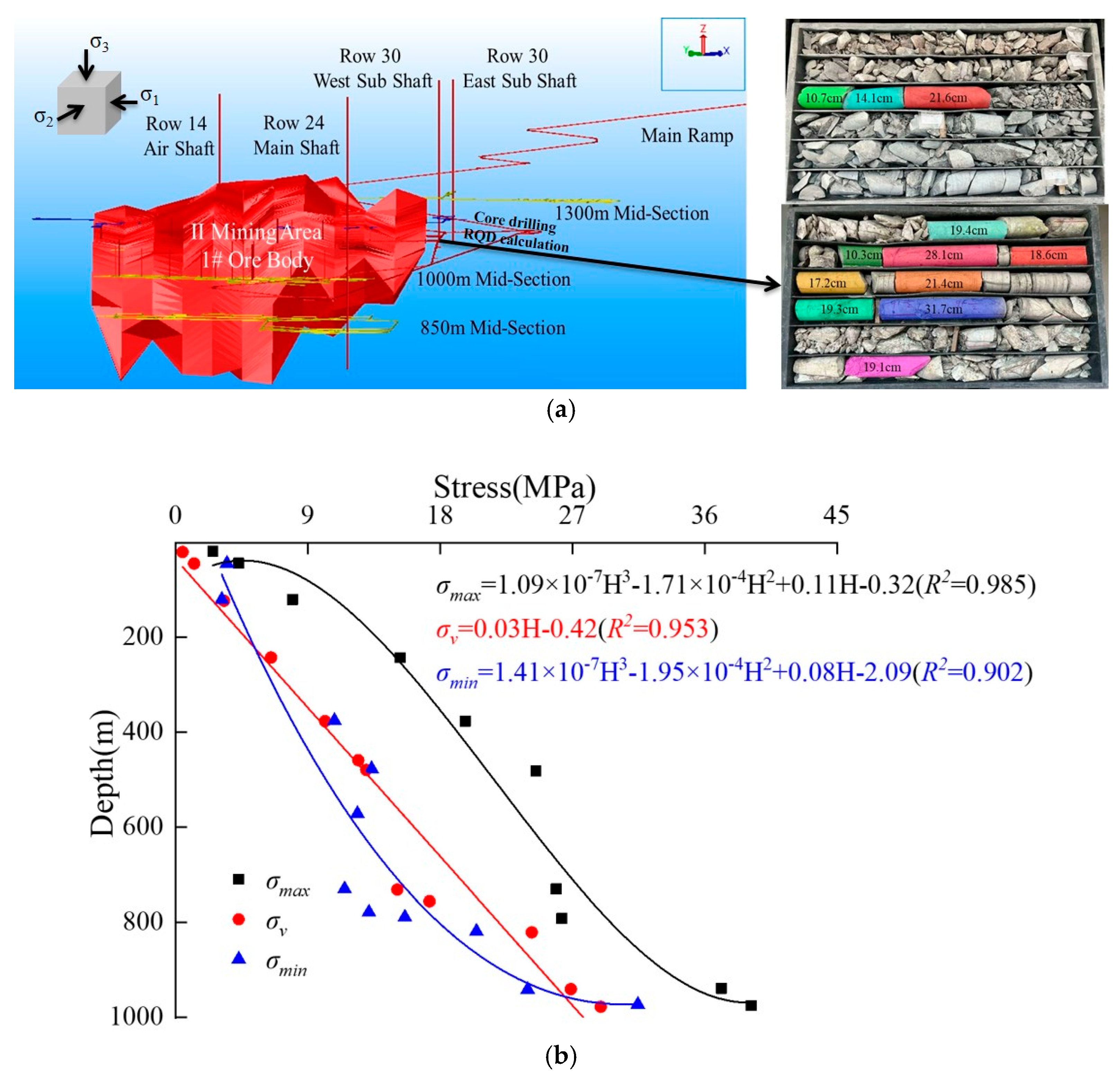
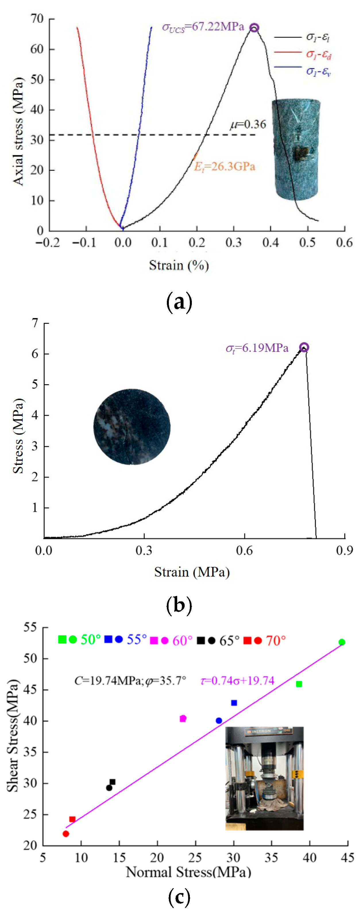
As shown in Figure 2, the development system of Jinchuan II Mining Area adopts a combined development mode of a main ramp and a vertical shaft. In situ stress testing is carried out using the hollow inclusion stress relief method. The in situ stress measurement is conducted in other areas of Jinchuan II Mine. Fitting analysis of the statistical results reveals that the in situ stress is dominated by horizontal stress, with the maximum horizontal in situ stress exceeding 50 MPa and the lateral pressure coefficients being 1.15 and 1.80, respectively. The Rock Quality Designation (RQD) value of the roadway surrounding rock is 29. As shown in Figure 3, Poisson’s ratio, elastic modulus, and unconfined compressive strength (UCS) are obtained through uniaxial compression tests; tensile strength is obtained through Brazilian splitting tests; and cohesion and internal friction angle are obtained through variable-angle shear tests. The basic physical and mechanical properties of the rock mass are shown in Table 1. Due to the strong rheological properties of deep rock masses, the surrounding rock of the roadway undergoes various forms of structural damage, mainly including roof crushing failure, shear dislocation of the sidewall surrounding rock, and tensile floor heave failure. The surrounding rock of deep roadways generally exhibits a full-section convergence and deformation mode, which not only increases the number of roadway repairs but also severely restricts the driving efficiency and raises the roadway repair cost.

2.2. Construction and Reliability Verification of Numerical Model

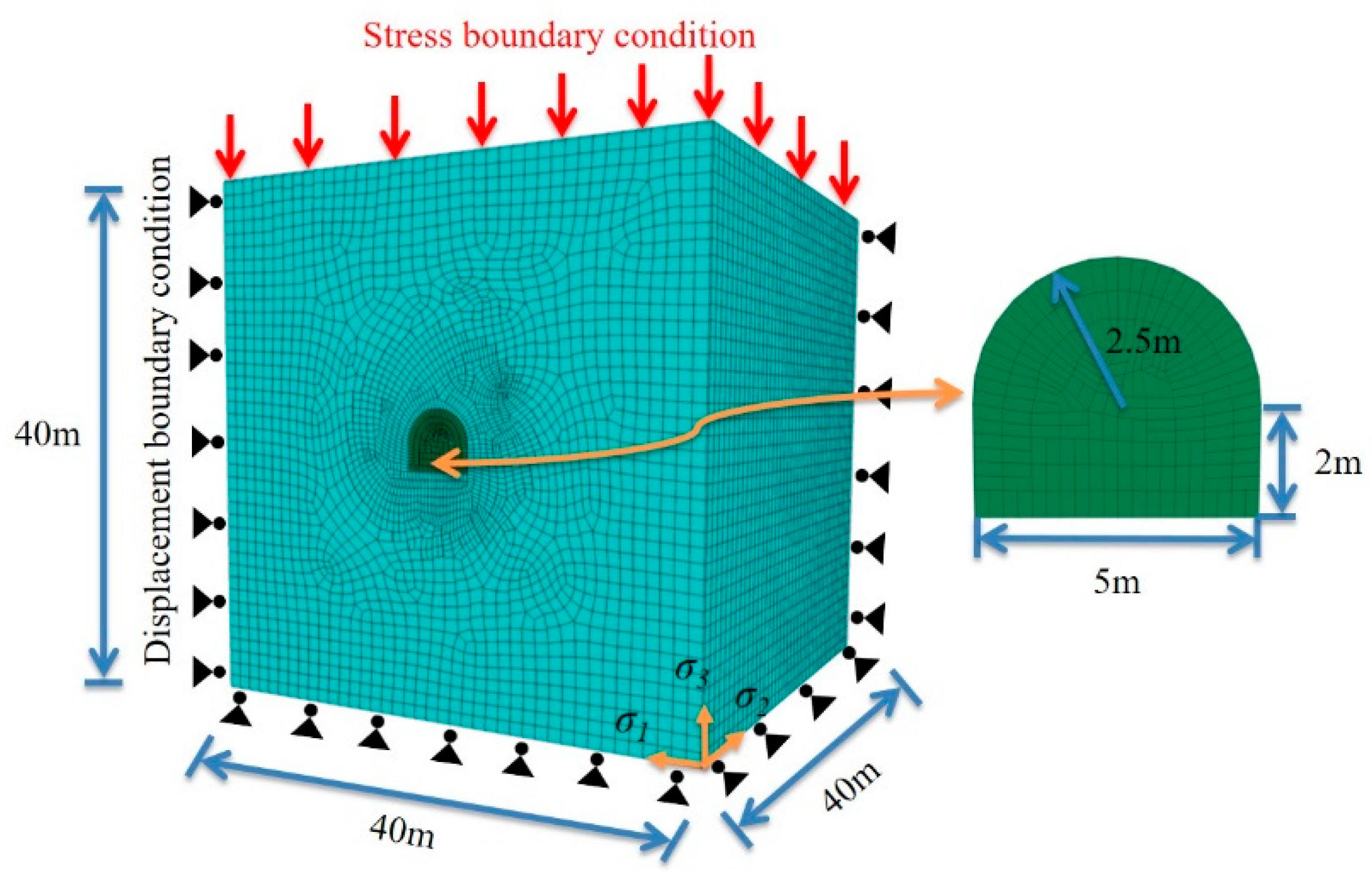
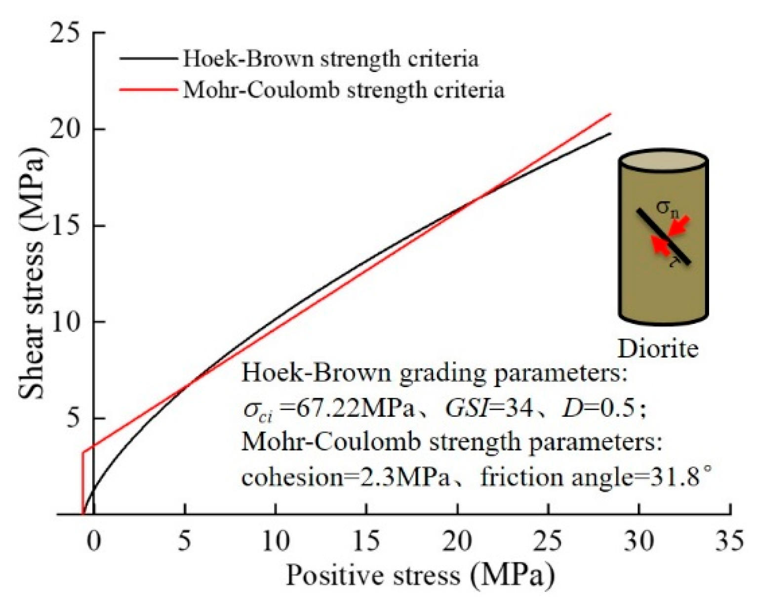
As shown in Figure 4, in order to study the evolution laws of the magnitude and direction of the maximum, intermediate, and minimum principal stresses during the excavation and unloading process of the surrounding rock in deep roadways, this paper constructs a three-dimensional numerical model based on the FLAC3D numerical simulation software. The numerical model is a cube with a side length of 40 m, and the roadway cross-section is a standard straight-wall semicircular arch commonly used in the Jinchuan mining area. The nodes at the bottom and surrounding sides of the numerical model adopt sliding displacement boundary conditions, where the boundaries are only fixed in displacement in their normal direction, while sliding is allowed in the direction parallel to the normal direction. Stress boundary conditions are applied to the nodes at the top of the numerical model to simulate the self-weight stress of the unmodeled rock strata. The maximum principal stress σ1 (58.85 MPa) of the initial stress field in the numerical model is set to be perpendicular to the roadway advance direction (along the X-axis), the intermediate principal stress σ2 (37.47 MPa) parallel to the roadway advance direction (along the Y-axis), and the minimum principal stress σ3 (32.58 MPa) distributed along the vertical direction (along the Z-axis). As shown in Figure 5, the geological strength index GSI values for deep roadway surrounding rock are firstly determined. Secondly, the grading parameters and strength parameters of the generalized Hoek–Brown strength criterion are calculated. Finally, the Hoek–Brown strength criterion grading parameters and strength parameters of different lithological surrounding rock are imported into RockData 3.0 software to establish the Hoek–Brown strength criterion and Mohr–Coulomb strength relationship. The surrounding rock of the deep roadway is altered diorite. The specific mechanical parameters are shown in Table 2. The constitutive model assigned to the numerical simulation elements is the ideal elastoplastic model (Mohr–Coulomb constitutive model).
σ 1 = σ 3 + σ c i ( m b σ 3 σ c i + s ) a
m b = m i exp ( G S I 100 28 14 D )
s = exp ( G S I 100 9 3 D )
a = 1 2 + exp ( G S I / 15 ) exp ( 20 / 3 ) 6
where σci is the uniaxial compressive strength of the rock, MPa; mb, s, a are semi-empirical parameters for rock mass properties; mi is the rock material constant; and D is the weakening factor of the rock mass disturbed by anthropogenic or natural factors, taking the value of 0.5.
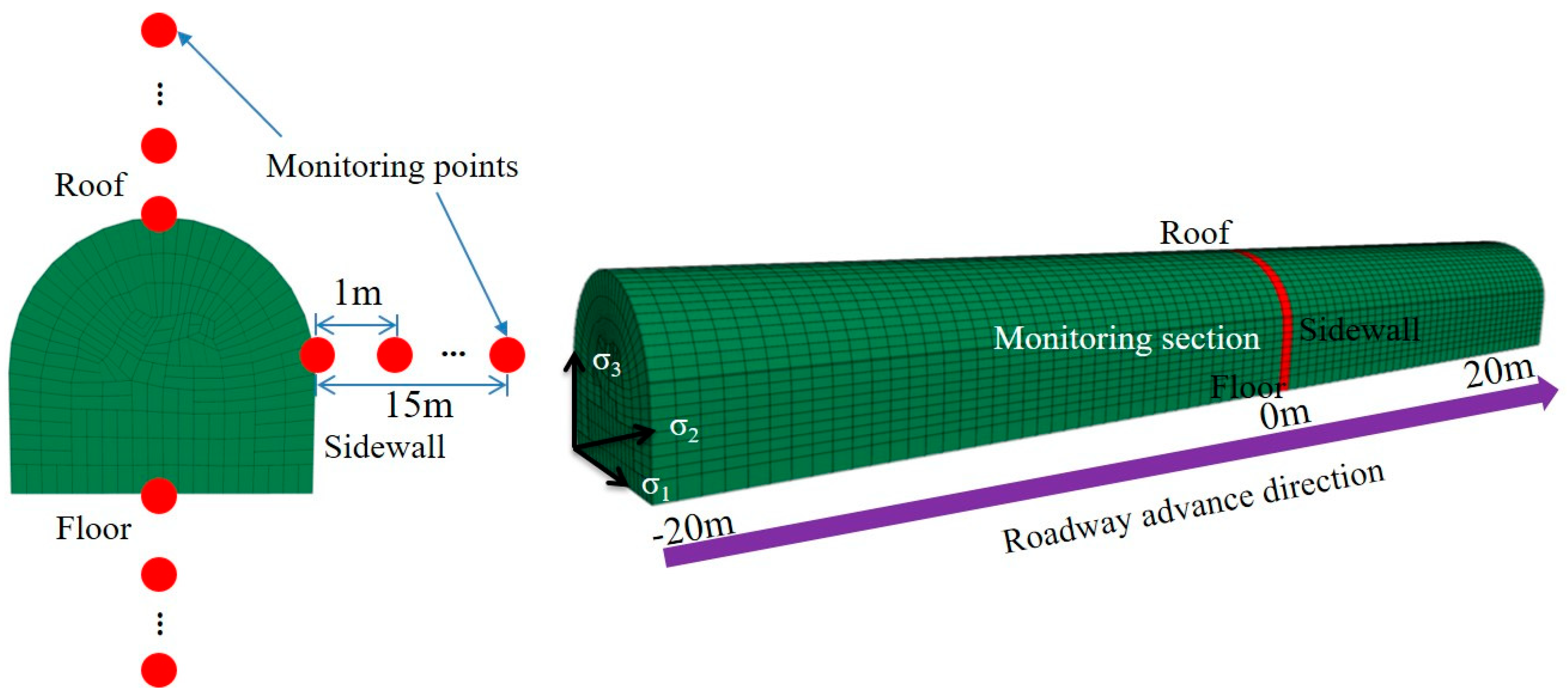
As shown in Figure 6, due to the fact that the traditional drilling and blasting technology is adopted for roadway excavation in the Jinchuan mining area, with an advance footage of approximately 2 m, the roadway excavation is carried out in a step-by-step manner, with a step distance of 2 m. Stress monitoring points are arranged on the roof, two sidewalls, and floor of the deep roadway, respectively, with 15 monitoring points at each location, and the distance between each monitoring point is 1 m. The mining distance of the deep roadway along the Y-axis is 40 m, and the stress monitoring points are arranged at the middle position of the Y-axis, with an advancing distance L = 0.
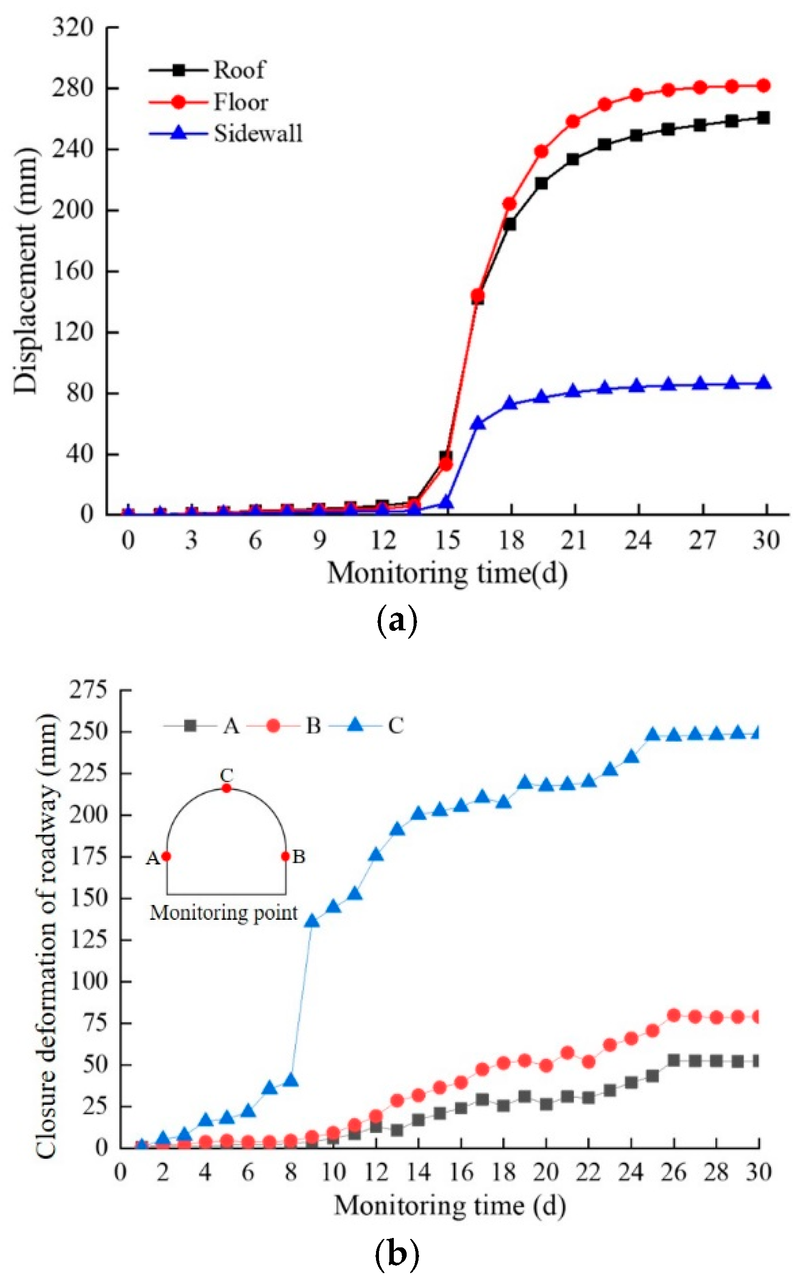
As shown in Figure 7, to verify the reliability of the numerical model, displacement monitoring points are arranged on the roof, floor, and sidewall surrounding rocks of the 1150 m sublevel ramp in Jinchuan II Mining Area. The deformation of the roadway surrounding rocks is monitored in real time by a multi-point displacement meter, with an overall monitoring period of 30 d. Since installing multi-point displacement meter on the roadway floor for displacement monitoring would interfere with vehicle traffic, no on-site monitoring of the floor surrounding rock is conducted. The multi-point displacement meter is 8 m, contains 5 monitoring points, and can cover deformation monitoring in the depth range of 0–6 m. It is mainly arranged on the roof and sidewalls of deep roadways. The displacement vectors of the monitoring points in the surrounding rock of the deep roadway all point to the free surface. The deformation of the floor surrounding rock is the largest, followed by that of the two sidewalls, with the maximum deformation reaching 310 mm. The deformation magnitude of the surrounding rock in the deep roadways of the Jinchuan mining area shows a variation trend of first increasing and then decreasing as the monitoring time increases. Due to the three stages of rapid accumulation, sudden release, and slow adjustment of elastic energy in the surrounding rock after the excavation and unloading of deep roadways, the convergent deformation of the surrounding rock also undergoes three stages: slow initiation, rapid development, and stable growth. Since the deformation of the roadway surrounding rock extracted from the numerical simulation is close to the on-site monitoring results and the variation trends are consistent, the subsequent research on the rotation characteristics of mining-induced stress can be carried out.

3. Evolution Characteristics of Mining-Induced Stress in Surrounding Rock During Excavation and Unloading of Deep Roadways

3.1. Mechanism of Principal Stress Rotation in Surrounding Rock

As shown in Figure 8, before being disturbed by mining activities, the surrounding rock of the deep roadway is in a state of triaxial stress. When the surrounding rock of the roadway is disturbed by excavation, the initial stress state of the rock mass is broken, and the stress field begins to redistribute, which is mainly manifested in two aspects: the change in the magnitude of the principal stress and the rotation of its direction. Obvious shear dislocation phenomena begin to occur between deep rock layers, and shear stress emerges inside the surrounding rock. The new principal stress plane of the surrounding rock can be determined by the Mohr stress circle, and the angle between the new principal stress plane and the initial principal stress plane is the principal stress rotation angle θ.
In the FLAC3D numerical simulation software, the six stress components, namely, σx, σy, σz, τxy, τyz, and τzx, of each monitoring point can be extracted through the Zone.stress() function. According to the theory of generalized plastic mechanics [31], the three principal stress directions acting on a rock mass element are orthogonal to each other. Therefore, the rotation angle θ of the principal stress is calculated by solving the cosine values of the angles between the three principal stress directions and their respective plane axes (X, Y, Z), to describe the variation process of principal stress directions. Reference [12] provides the calculation formulas for the cosine values Li, Mi, Ni corresponding to the principal stress σi (i = 1, 2, 3) and the X, Y, Z axes. The angles αi, βi, γi between the principal stress σi and the X, Y, Z axes can be solved by Equations (5)–(9).
L i = σ i + τ x y τ y z σ y ( σ x σ i ) ( σ y σ i ) τ x y 2 2 + τ x y τ z x ( σ x σ i ) 2 + τ x y τ y z ( σ y σ i ) 2
M i = σ i + τ x y τ z x σ x ( σ x σ i ) ( σ y σ i ) τ x y 2 2 + τ x y τ z x ( σ x σ i ) 2 + τ x y τ y z ( σ y σ i ) 2
N i = ( σ x σ i ) ( σ y σ i ) τ x y 2 ( σ x σ i ) ( σ y σ i ) τ x y 2 2 + τ x y τ z x ( σ x σ i ) 2 + τ x y τ y z ( σ y σ i ) 2
L i 2 + M i 2 + N i 2 = 1
α i = arccos L i β i = arccos M i γ i = arccos N i
As shown in Figure 9, after the surrounding rock of the deep roadway is disturbed by excavation, the directions of the maximum, intermediate, and minimum principal stresses change, and their variation process can be described by the dip angle and azimuth angle. Define the rotation dip angle θi of the initial principal stress and secondary principal stress as the angle between the direction of the principal stress and the XOY plane; define the rotation azimuth angle ψi of the principal stress as the angle through which the projection of the principal stress direction onto the XOY plane rotates clockwise to the reference point.
It can be known from Equation (9) that the rotation dip angle θi and rotation azimuth angle ψi of the principal stress can be calculated through the angles αi, βi, γi between the principal stress σi and the X, Y, Z axes.
θ i = 90 γ i
ψ i = 18 0 arctan ( L i N i )

3.2. Variation Process of the Principal Stress Magnitude in the Surrounding Rock

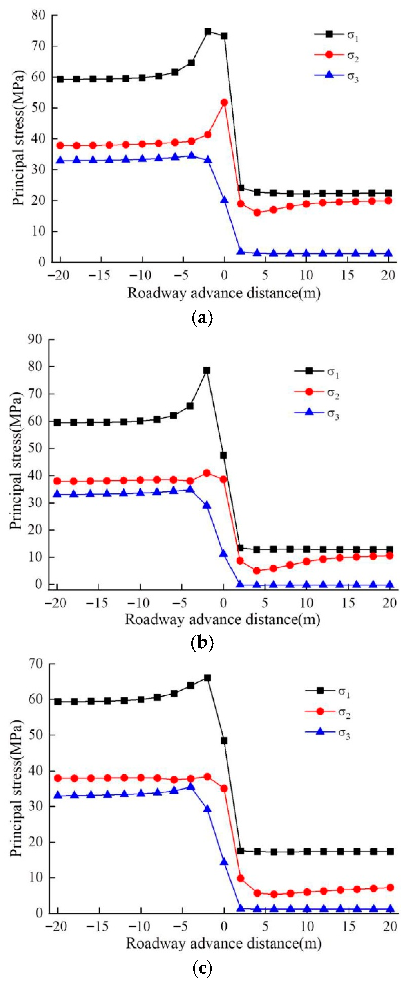
As shown in Figure 10, this is the variation process of the principal stress magnitude at different monitoring points in the surrounding rock of the deep roadway. When the driving face is in front of the monitoring section, with the increase in the roadway advance distance, the maximum, intermediate, and minimum principal stresses of the surrounding rock begin to increase slowly, which is mainly due to the small disturbance of the monitoring section in the early stage of roadway excavation. When the disturbance range of roadway excavation is 4 m away from the monitor section, the stress magnitude of the surrounding rock begins to adjust drastically. At this time, the maximum and intermediate principal stresses of the surrounding rock around the roadway increase rapidly, while the minimum principal stress starts to decrease, indicating that the excavation disturbance has a severe impact on the principal stress magnitude of the monitoring section. When the disturbance from roadway excavation advances to the monitor section, the principal stress of the surrounding rock reaches its peak value. The peak stress of the surrounding rock at the roadway floor is the largest (78.71 MPa) with a stress concentration factor of approximately 1.34; the peak stress of the surrounding rock at the two sides is the smallest (66.15 MPa) with a stress concentration factor of about 1.12, which indicates that the surrounding rock at the roadway floor is failing more severely. During the stage of severe adjustment of the principal stress in the roadway surrounding rock, the magnitude of the maximum principal stress changes most drastically, while the magnitude of the minimum principal stress changes relatively slowly. When the roadway driving face is located behind the monitoring section, the maximum and minimum principal stresses begin to decrease rapidly, and when reaching the position 2 m away from the monitoring section, the principal stresses gradually tend to stabilize. The intermediate principal stress shows a trend of first decreasing and then increasing, and gradually stabilizes at a position 10 m away from the monitoring section. Moreover, after the principal stress of the surrounding rock stabilizes, it is significantly lower than the initial stress value.

3.3. Evolution Law of Principal Stress Direction in Surrounding Rock

As shown in Figure 11, this is the process of changes in the principal stress direction of the rock mass at different monitoring points in the deep roadways of the Jinchuan mining area. When the roadway driving face is far from the monitoring section, the degree of change in the principal stress dip angles of the rock mass in the roadway roof, floor, and both sidewalls is relatively slow. The rotation dip angle θ1 of the maximum principal stress in the surrounding rock of the deep roadway increases slowly from the initial 0°, while the rotation dip angles θ2 and θ3 of the intermediate and minimum principal stresses decrease slowly from the initial 90°. When the disturbance range of roadway excavation is 6 m away from the monitor section, the principal stress direction of the surrounding rock begins to adjust drastically. The principal stress direction of the surrounding rock at the sidewalls undergoes the most significant change, while that of the surrounding rock at the floor changes the least. When the disturbance from roadway excavation advances to the monitor section, the rotation of the directions of the maximum and intermediate principal stresses in the surrounding rock reaches their peak values. The rotation dip angles of the maximum principal stress (θ1) in the surrounding rock of the roof, floor, and sidewalls increase from 0° to their maximum values, which are 40.91°, 33.22°, and 88.94°, respectively; while the rotation dip angles of the intermediate principal stress (θ2) decrease from 90° to their minimum values, which are 38.74°, 35.39°, and 1.13°, respectively. When the driving face is behind the monitor section, the rotation dip angle of the maximum principal stress in the roadway surrounding rock gradually decreases and tends to stabilize, while the rotation dip angle of the intermediate principal stress shows a trend of first increasing, then decreasing, and finally stabilizing. When the roadway driving face is approximately 2 m away from the monitoring section, the rotation dip angle θ3 of the minimum principal stress in the rock mass decreases from 90° to its minimum values, which are 32.73°, 38.81°, and 3.05° respectively. As the roadway driving face moves away from the monitoring section, the rotation dip angle θ3 of the minimum principal stress in the roadway rock mass gradually tends to stabilize.
It can be known from the variation process of the magnitude and direction of the principal stress in the rock mass of the deep roadways in the Jinchuan mining area that the variation trends of the magnitude and direction of the principal stress in the surrounding rock are similar. Given that the drastic changes in the direction of the principal stress in the roadway surrounding rock occur earlier than those in the magnitude of the principal stress, while the stabilization of the principal stress direction lags behind that of the principal stress magnitude, it can be inferred that after the excavation and unloading of the surrounding rock in the deep roadways of the Jinchuan mining area, and before the rock mass reaches the peak stress, the propagation path of the failure fractures in the rock mass undergoes corresponding adjustments due to the change in the principal stress direction. Hence, the impact of principal stress rotation on the deformation and failure of the surrounding rock should be taken into account.
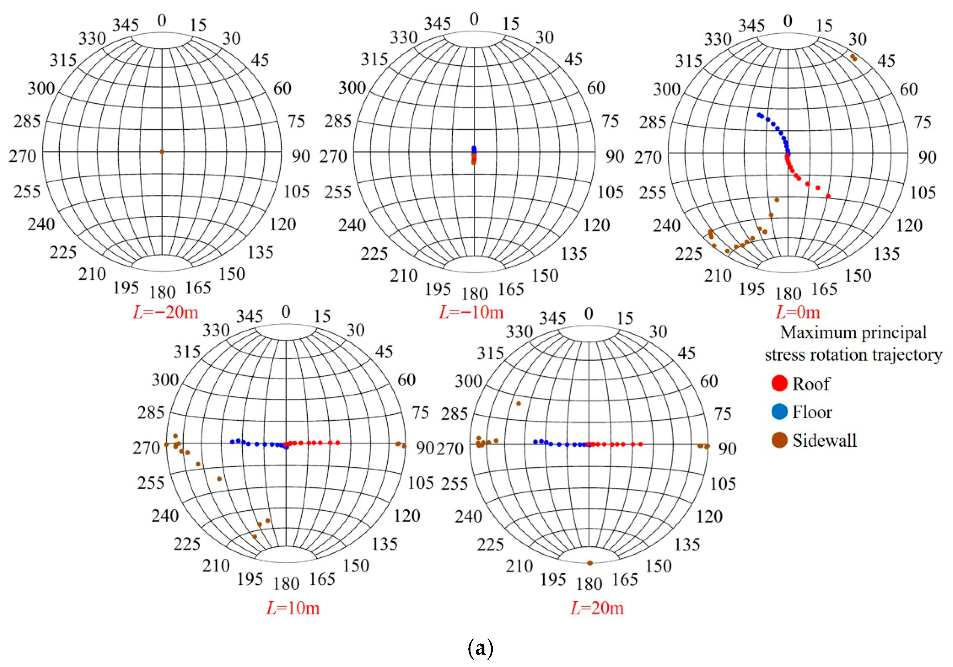
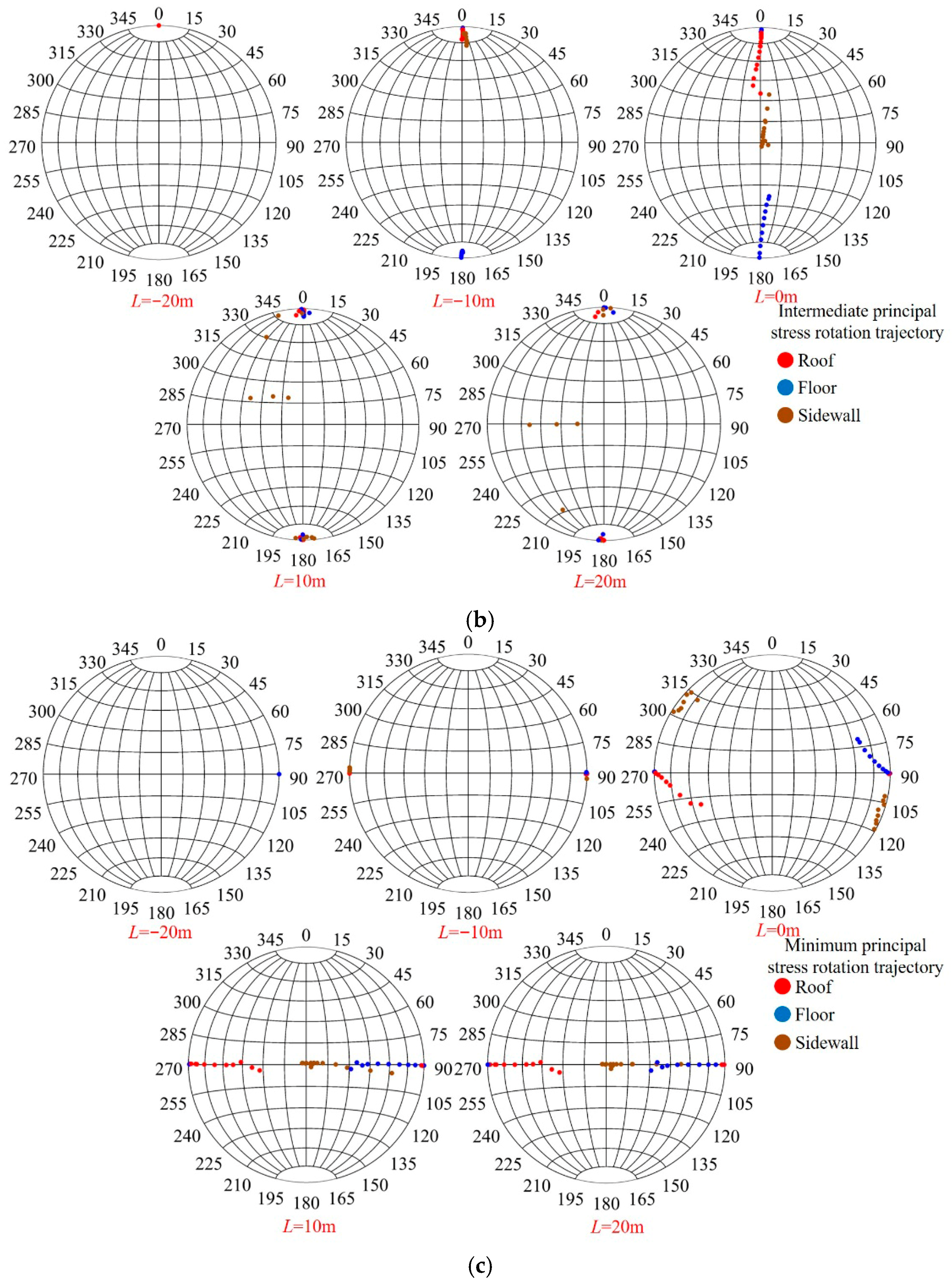
As shown in Figure 12, these are the mining-induced stress rotation trajectories of the surrounding rock in the roof, floor, and sidewalls of the deep roadway. The mining-induced stress rotation trajectory of the surrounding rock in deep roadways refers to the path that mining-induced stress undergoes from its initial state to the mining-induced state. The stereographic projection enables the effective representation of spatial three-dimensional information on a two-dimensional plane, and the principal stress direction of the rock mass can be described by points in the stereographic projection. In the stereographic projection, the center position indicates that the principal stress direction is horizontal, while the peripheral positions indicate that the principal stress direction is vertical. The circumferential scale of the stereographic projection represents the azimuth angle ψi of the principal stress direction inside the roadway rock mass, and the radial scale represents the dip angle θi of the principal stress direction inside the surrounding rock. Therefore, the rotation trajectory of mining-induced stress can be described by the change in the position of the points representing the principal stress in the stereographic projection.
Given that the dip angle range of each principal stress in the rock mass of deep roadways is from 0° to 90° and the azimuth angle ranges from 0° to 360°, under the initial state, the dip angle and azimuth angle of the maximum principal stress are 0° and 90°, respectively; the dip angle and azimuth angle of the intermediate principal stress are 90° and 0°, respectively; and the dip angle and azimuth angle of the minimum principal stress are 90° and 90°, respectively. When the roadway driving face is located 10 m in front of the monitoring section, the direction of the principal stress in the rock mass begins to change significantly; furthermore, as the distance from the roadway contour surface increases, the rotation angles of the maximum, intermediate, and minimum principal stresses all start to decrease. The direction of the maximum principal stress in the rock mass of the roof and two sidewalls of the deep roadway begins to rotate downward, while that in the surrounding rock of the floor begins to deflect upward, indicating that both the dip angle and azimuth angle of the maximum principal stress direction in the roadway surrounding rock are gradually increasing. The dip angle and azimuth angle of the maximum principal stress in the floor surrounding rock exhibit the largest rotation amplitude, with the dip angle ranging from 0° to 4.7° and the azimuth angle ranging from 90° to 180°. Along the survey line, the rotation amplitudes of both the intermediate and minimum principal stresses in the floor surrounding rock remain the largest, followed by those in the roof surrounding rock, with the smallest observed in the sidewall surrounding rock. When the roadway driving face advances to the monitoring section, the variation degree of the maximum, intermediate, and minimum principal stresses in the rock mass becomes more significant. Furthermore, the variation degree of the maximum principal stress in the surrounding rock of the roadway roof and floor increases slowly as the distance from the contour surface increases, while the variation degree of the maximum principal stress in the surrounding rock of the two sidewalls shows a trend of first increasing and then decreasing with the increase in distance from the contour surface.
The rotation directions of the maximum principal stress in the surrounding rock of the roadway roof and floor are 32.5°/143° and 40.9°/317°, respectively. The rotation direction of the maximum principal stress in the sidewall surrounding rock reaches a peak at 12 m along the survey line, approximately 82.9°/43.7°. This indicates that the direction of the maximum principal stress in the rock mass of the two sidewalls has rotated from being parallel to the X-axis to being perpendicular to the X-axis. The angle of the intermediate principal stress direction in the roadway roof surrounding rock shows a trend of first increasing and then decreasing as the distance from the contour surface increases. The angle of the intermediate principal stress direction in the floor surrounding rock exhibits a trend of slowly increasing with the increasing distance from the contour surface, while the intermediate principal stress direction in the sidewall surrounding rock rotates from being parallel to the Y-axis to being perpendicular to the Y-axis. The minimum principal stress in the roadway roof surrounding rock exhibits the highest rotational sensitivity, followed by that in the floor surrounding rock, with the lowest in the sidewall surrounding rock. When the driving face is 20 m behind the monitor section, the rotation degree of the principal stress in the roadway surrounding rock gradually tends to stabilize compared with the previous stage. As the distance from the monitoring surface increases, the rotation angle of the maximum principal stress direction in the rock mass of the roof and floor gradually increases, while the angle of the maximum principal stress direction in the rock mass of the two sidewalls gradually decreases. At this time, the intermediate principal stress in the rock mass of the roof and floor of the deep roadway gradually returns to its initial state. Meanwhile, the minimum principal stress in the rock mass of the two sidewalls of the roadway changes from its initial state of being parallel to the Z-axis to a state of being perpendicular to the Z-axis. The angles of the minimum principal stress direction in the surrounding rock of the roadway roof and floor show an increasing trend as the distance from the contour surface increases.
As shown in Figure 13, by integrating the principal stress rotation characteristics of the three survey lines on the monitor section of deep roadway surrounding rock, the schematic diagram of the principal stress direction rotation in the surrounding rock after excavation disturbance can be drawn. After the excavation and unloading of deep roadways, the secondary stress causes different forms of structural failure to the surrounding rock. The failure range is approximately 4 m near the roof and floor surrounding rock, and about 2 m near the sidewall surrounding rock. The rotation dip angles and azimuth angles of the maximum principal stress in the surrounding rock of the roadway roof and floor show a trend of first increasing and then decreasing as the excavation step increases. As the roadway excavation step increases, the rotation dip angle of the maximum principal stress in the rock mass of the two roadway sidewalls first increases and then decreases, while the variation trend of the rotation azimuth angle of the maximum principal stress is the opposite. Ultimately, the direction of the principal stress in the rock mass located in the original rock stress area gradually returns to its initial state. Therefore, after the excavation and unloading of deep roadway surrounding rock, the rotation of principal stress leads to the generation of a large number of macroscopic fractures inside the rock mass, resulting in the rapid development and expansion of the surrounding rock plastic zone. The key areas for support should focus on the range where the principal stress rotation is intense.

4. Mining-Induced Stress Rotation Guiding Roadway Surrounding Rock Control

4.1. Determination of Dominant Rotation Trajectory of Mining-Induced Stress

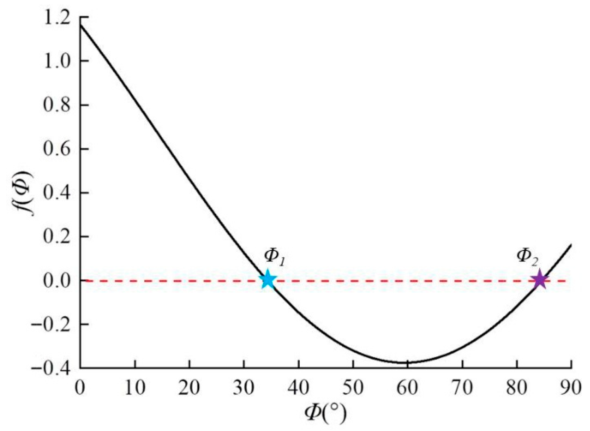
Due to the fact that the development depth of the underground engineering in Jinchuan II Mine Area exceeds 1100 m, the surrounding rock of the deep roadway has undergone long-term geological tectonic movements, resulting in a large number of joints and fissures in the rock mass. Dominant joint and fissure groups in the surrounding rock of deep roadways can be obtained through on-site surveys. According to rock mechanics theory, the bearing capacity of roadway surrounding rock is affected by the spatial positional relationship between the loading direction and the direction of joints and fissures [32]. Therefore, during the development of large main ramps, the mining-induced stress rotation trajectory of the surrounding rock can be controlled by adjusting the roadway advancement direction, the principal stress direction, and the dip angle direction of the dominant joint and fissure groups can satisfy a certain relationship. An advantageous stress rotation trajectory can effectively enhance the self-stabilization capacity of the surrounding rock and reduce the number of roadway repair operations. Reference [33] provides the determination formulas for the uniaxial compressive strength of intact rock and fractured rock masses. When the calculation result of Equation (13) is smaller than that of Equation (12), it indicates that the stability of roadway surrounding rock is severely affected by the direction of joints and fissures, and the rock masses exhibit obvious damage and deterioration. At this time, the angle Φ between the direction of the maximum principal stress and the external normal direction of the joints and fissures surface satisfies Equation (14).
R c = 2 C cos φ 1 sin φ
R c f = 2 C f sin 2 ϕ ( 1 c o t ϕ tan φ f )
f ( ϕ ) = C f cot φ f ( 1 sin φ ) 2 C cos φ + cos 2 ϕ cot φ f sin ϕ cos ϕ 0
where RC and RCF are the uniaxial compressive strengths of intact rock and fractured rock masses, in MPa; C, φ and Cf, φf are the cohesion and internal friction angles of intact rock and fractured rock masses, respectively, in MPa and °.
As shown in Figure 14, this is the curve shape distribution of the function f(Φ). When the angle Φ between the direction of the maximum principal stress and the external normal direction of the joints and fissures surface is equal to Φ1 or Φ2, the function f(Φ) is equal to 0 at this point. When the angle Φ is within the interval [Φ1, Φ2], the mechanical properties of the deep roadway rock mass are greatly affected by the occurrence of joints and fissures, and the excavation unloading of the surrounding rock reduces its overall stability. Therefore, the interval [Φ1, Φ2] can be defined as the sensitive area of the principal stress direction in the roadway surrounding rock. Since the occurrence distribution of joints and fissures in the deep roadway surrounding rock is mainly determined by early geological tectonic movements and is less affected by mining disturbances. The angle Φ between the direction of the maximum principal stress and the external normal direction of the joint and fissure surfaces can be kept away from the principal stress sensitive interval of the surrounding rock by changing the mining-induced stress rotation trajectory, to achieve the goal of improving the self-stabilization capacity of the roadway surrounding rock.
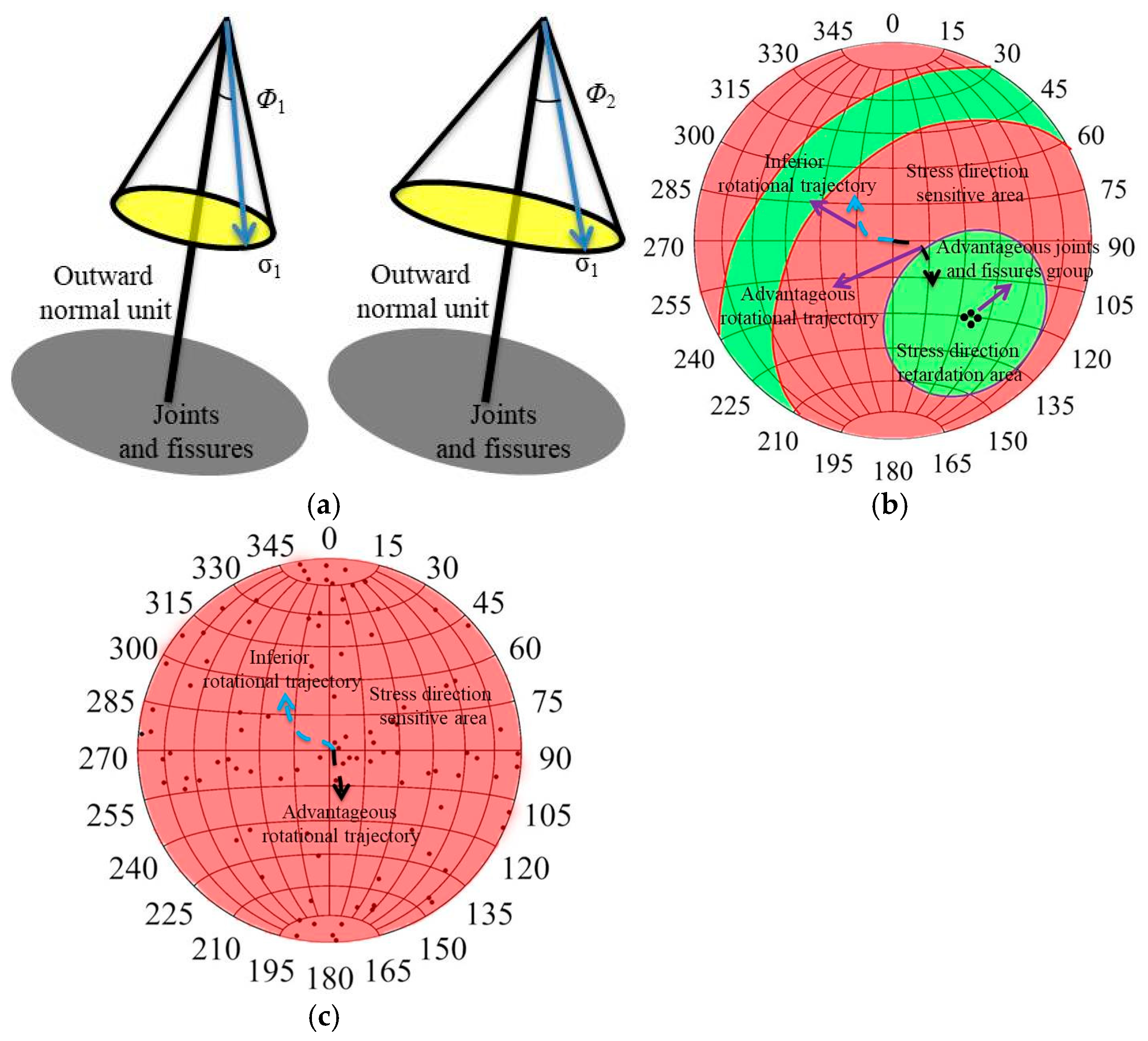
As shown in Figure 15, the angles Φ1 and Φ2 between the direction of the maximum principal stress and the external normal direction of the dominant joint-fissure groups are represented as boundary lines in the stereographic projection diagram. The red area indicates that the overall strength of the deep roadway rock mass is greatly affected by mining-induced stress, and this area is defined as the sensitive area for the rotation direction of the principal stress. The green area indicates that the bearing capacity of the deep roadway surrounding rock is less affected by mining-induced stress, and it is defined as the principal stress direction retardation area. When the occurrence of the dominant joint-fissure groups in the deep roadway surrounding rock is determined, the sensitive area of the principal stress direction partially covers the stereographic projection diagram. To prevent the rock mass from increasing damage and deterioration due to mining-induced stress rotation, the rotation trajectory of the maximum principal stress in the surrounding rock can be made to deviate from the principal stress sensitive area or the range where the rotation trajectory falls into the principal stress sensitive area can be shortened by changing the roadway advancement direction. This turns the rotation trajectory of the principal stress into a dominant rotation trajectory, thereby improving the self-stabilization capacity of the roadway surrounding rock. When the occurrence of joints and fissures in the deep roadway surrounding rock is randomly distributed, the sensitive area of the principal stress direction fully covers the stereographic projection diagram. At this time, the rotation trajectory of mining-induced stress after excavation disturbance in deep roadways will drive the surrounding rock to undergo damage and deterioration, leading to instability of the roadway structure. To reduce the degree of damage and deterioration of deep roadway surrounding rock, the amplitude of the maximum principal stress rotation trajectory can be reduced by changing the roadway advancement direction, thereby shortening the extension length of the rotation trajectory in the stereographic projection diagram.

4.2. Asymmetric Coupling Support Scheme

After the excavation and unloading of deep roadways, the direction and magnitude of the principal stress in the rock mass change significantly, leading to varying degrees of non-uniform structural failure in the surrounding rock. Therefore, based on the influence of mining-induced stress rotation in deep roadways on the failure of the surrounding rock, the conventional support methods in Jinchuan II mining area are optimized, with enhanced support applied to the surrounding rock of the roof and floor where the principal stress rotates violently. The parameters of the anchor structural elements are shown in Table 3. As shown in Figure 16, the conventional support scheme fails to effectively control the long-term rheological failure of the surrounding rock in the roadway roof, and the surrounding rock in the floor is not effectively supported. Under unsupported conditions, the maximum plastic zone depth of the surrounding rock in deep roadways is approximately 4.16 m. Therefore, for the surrounding rock of the two sides of the deep roadway, the conventional 2.25 m-long mortar bolts are still used for support, while the surrounding rock of the roof and floor is supported by 4.3 m-long anchor cables with a spacing and row spacing of 1 × 1 m. Under the original support conditions, the maximum plastic zone depth of the surrounding rock is approximately 3.94 m. The plastic zones in the floor and roof surrounding rock have not been effectively restrained, and they still belong to risk areas. Under the condition of asymmetric coupling support, the maximum plastic zone depth of the surrounding rock is approximately 2.31 m. The designed anchor length exceeds the plastic zone range of the surrounding rock in the entire cross-section of the roadway, allowing the anchors to fully exert their suspension effect. Compared with the unsupported condition, both the original support and the new support can reduce the plastic zone volume of the roadway surrounding rock by approximately 29.5% and 63.4% respectively, indicating that the asymmetric coupling support can significantly improve the stability of rock masses.

5. Conclusions

(1) For the straight-wall semicircular arch-shaped diorite roadway, after the excavation and unloading of the surrounding rock, the variation processes of the magnitude and direction of the maximum, intermediate, and minimum principal stresses in the rock mass are similar, all following a trend of slow change at first, then drastic change, and finally stabilization. When the driving face is 4 m away from the monitor section, the adjustment of the principal stress magnitude in the surrounding rock is the most drastic, and the principal stress decreases rapidly after reaching its peak value. As the roadway driving face moves away from the monitoring section, the variation degree of the rock mass’s principal stress magnitude gradually stabilizes and becomes significantly lower than the initial in situ stress value.
(2) For the straight-wall semicircular arch diorite roadway, the maximum principal stress rotation angle of the surrounding rock shows a trend of first increasing and then decreasing with the increase in excavation step distance, while the rotation angles of the intermediate and minimum principal stresses show a trend of first decreasing and then increasing with the increase in excavation step distance. Moreover, both the direction and magnitude of the principal stress in the rock mass located in the original rock stress area gradually return to their initial state.
(3) The characteristics of mining-induced stress rotation affect the bearing capacity and failure mode of the surrounding rock in deep roadways. Based on the spatial distribution characteristics of joints and fissures in the surrounding rock, the mining-induced stress rotation sensitive area can be characterized by stereographic projection diagrams. When the occurrence of joints and fissures is stable, the mining-induced stress rotation sensitive area partially covers the stereographic projection diagram, and the dominant mining-induced stress rotation trajectory should deviate from the sensitive area. When the occurrence of joints and fissures is randomly distributed, the mining-induced stress rotation sensitive area fully covers the stereographic projection diagram, and the dominant mining-induced stress rotation trajectory should reduce the rotation amplitude and shorten the extension length.
(4) Based on the variation process of the magnitude and direction of the principal stress in the surrounding rock of deep roadways, an asymmetric coupling support is proposed to strengthen the positions where the principal stress rotation in the rock mass around the anchorage is intense. The maximum plastic zone depth of the new support is reduced to 2.31 m, and the plastic zone volume is decreased by 63.4%. Asymmetric strong anchoring can control the degree of damage and deterioration of surrounding rock caused by mining-induced stress rotation, and significantly improve the overall stability of rock masses.

Author Contributions

Resources, D.L.; Writing—original draft, H.G.; Writing—review & editing, Z.H., W.R. and P.L.; Funding acquisition, D.L. All authors have read and agreed to the published version of the manuscript.

Funding

The authors are thankful for the financial support from the National Natural Science Foundation of China (Nos. 52374153 and 52504110) and Natural Science Foundation of Changsha of China (kq2502150).

Data Availability Statement

Data will be made available on reasonable request.

Conflicts of Interest

The authors declare that they have no known competing financial interests or personal relationships that could have appeared to influence the work reported in this paper.

References

  1. Dai, L.; Feng, D.; Pan, Y.; Wang, A.; Ma, Y.; Xiao, Y.; Zhang, J. Quantitative principles of dynamic interaction between rock support and surrounding rock in rockburst roadways. Int. J. Min. Sci. Technol. 2025, 35, 41–55. [Google Scholar] [CrossRef]
  2. Zhang, C.; Li, D.; Su, X.; Luo, P.; Ma, J.; Zhu, Q. Fracture behavior of thermally treated granite under compression-shear loading. Int. J. Rock. Mech. Min. Sci. Géoméch. Abstr. 2024, 184, 105966. [Google Scholar] [CrossRef]
  3. Si, X.; Zhang, Z.; Li, X.; Yi, G.; Luo, Y.; Tan, L.; Han, K. Influences of maximum principal stress direction and cross-section shape on tunnel stability. J. Rock. Mech. Geotech. Eng. 2025, 17, 2159–2180. [Google Scholar] [CrossRef]
  4. Han, Z.; Li, D.; Li, X. Dynamic mechanical properties and wave propagation of composite rock-mortar specimens based on SHPB tests. Int. J. Min. Sci. Technol. 2022, 32, 793–806. [Google Scholar] [CrossRef]
  5. Gong, H.; Li, D.; Luo, P.; Ru, W.; Zhang, G.; Liu, Y. Floor heave mechanism and stiff control technology by I-beam for deep mine roadway. Eng. Fail. Anal. 2025, 175, 109600. [Google Scholar] [CrossRef]
  6. Zhao, C.; Li, Y.; Liu, G.; Meng, X. Mechanism analysis and control technology of surrounding rock failure in deep soft rock roadway. Eng. Fail. Anal. 2020, 115, 104611. [Google Scholar] [CrossRef]
  7. Yang, Z.; Tao, M.; Ranjith, P. Novel insights into grain size effect of stressed crystalline rock using weakened grain boundary model. Int. J. Rock. Mech. Min. Sci. Géoméch. Abstr. 2025, 189, 106098. [Google Scholar] [CrossRef]
  8. Li, G.; Ma, F.; Guo, J.; Zhao, H.; Liu, G. Study on deformation failure mechanism and support technology of deep soft rock roadway. Eng. Geol. 2020, 264, 105262. [Google Scholar] [CrossRef]
  9. Jing, H.; Wu, J.; Yin, Q.; Wang, K. Deformation and failure characteristics of anchorage structure of surrounding rock in deep roadway. Int. J. Min. Sci. Technol. 2020, 30, 593–604. [Google Scholar] [CrossRef]
  10. Han, Z.; Li, J.; Wang, H.; Zhao, J. Initiation and propagation of a single internal 3D crack in brittle material under dynamic loads. Eng. Fract. Mech. 2023, 285, 109299. [Google Scholar] [CrossRef]
  11. Wang, Z.; Sun, W.; Shui, Y.; Liu, P. Mining-induced stress rotation trace and its sensitivity to face advance direction in kilometer deep longwall panel with large face length. J. China Coal Soc. 2022, 47, 634–650. [Google Scholar]
  12. Liu, J.; Zhu, K.; Zuo, J.; Sun, K.; Sheng, Y.; Jia, B. Soft rock deformation and failure modes under principal stress rotation from roadway excavation. Bull. Eng. Geol. Environ. 2024, 83, 83. [Google Scholar] [CrossRef]
  13. Diederichs, M.; Kaiser, P.; Eberhardt, E. Damage initiation and propagation in hard rock during tunnelling and the influence of near-face stress rotation. Int. J. Rock. Mech. Min. Sci. Géoméch. Abstr. 2004, 41, 785–812. [Google Scholar] [CrossRef]
  14. Kaiser, P.; Yazici, S.; Maloney, S. Mining-induced stress change and consequences of stress path on excavation stability—A case study. Int. J. Rock. Mech. Min. Sci. Géoméch. Abstr. 2001, 38, 167–180. [Google Scholar] [CrossRef]
  15. Eberhardt, E. Numerical modelling of three-dimension stress rotation ahead of an advancing tunnel face. Int. J. Rock. Mech. Min. Sci. Géoméch. Abstr. 2001, 38, 499–518. [Google Scholar] [CrossRef]
  16. Du, S.; Wu, G.; Zhao, Y.; Ma, L. Re-orientation of principal stresses during tunnel excavation: Model development and support strategy. Alex. Eng. J. 2024, 107, 591–613. [Google Scholar] [CrossRef]
  17. Ma, J.; Li, D.; Du, S.; Han, Z.; Luo, P.; Zhao, J. Comparison of subcritical crack growth and dynamic fracture propagation in rocks under double-torsion tests. Int. J. Rock. Mech. Min. Sci. Géoméch. Abstr. 2023, 56, 7905–7922. [Google Scholar] [CrossRef]
  18. Colwell, M.; Frith, R. Why uniaxial compressive strength and Young’s modulus are commonly poor indicators of roadway roof stability-except in the tailgate. In Proceedings of the International Conference on Ground Control in Mining, Morgantown, WV, USA, 1–3 August 2006. [Google Scholar]
  19. Li, K.-S.; Luan, Y.-Q.; Zhang, J.-P.; Liu, C.-X. Experimental study on mechanical behavior, AE response and energy evolution of fissure-filled sandstone from mine roadway under conventional triaxial compression. Theor. Appl. Fract. Mech. 2024, 130, 104334. [Google Scholar] [CrossRef]
  20. Kong, P.; Jiang, L.; Jiang, J.; Wu, Y.; Chen, L.; Ning, J. Numerical analysis of roadway rock-burst hazard under superposed dynamic and static loads. Energies 2019, 12, 3761. [Google Scholar] [CrossRef]
  21. Zhou, X.; Zhang, D.; Nowamooz, H.; Jiang, C.; Ye, C. Investigation on damage and failure mechanisms of roadway surrounding rock triggered by dynamic–static combined loads. Rock. Mech. Rock. Eng. 2022, 55, 5639–5657. [Google Scholar] [CrossRef]
  22. Han, Z.; Yan, Z.; Li, D.; Wang, H.; Wang, H. Dynamic fracture mechanism from a pre-existing flaw in granite: Insights from grain-based modelling. Soil. Dyn. Earthq. Eng. 2024, 184, 108810. [Google Scholar] [CrossRef]
  23. Ma, Q.; He, X.; Zhou, Y.-G.; Chen, Y.-M.; Han, Y.-S. An approach to DEM simulation of hollow torsional shear tests for achieving general loading paths. Comput. Geotech. 2024, 172, 106402. [Google Scholar] [CrossRef]
  24. Zhou, H.; Jiang, Y.; Lu, J.; Gao, Y.; Chen, J. Development of a hollow cylinder torsional apparatus for rock. Rock. Mech. Rock. Eng. 2018, 51, 3845–3852. [Google Scholar] [CrossRef]
  25. Zuo, J.; Ma, Z.; Xu, C.; Zhan, S.; Liu, H. Mechanism of principal stress rotation and deformation failure behavior induced by excavation in roadways. J. Rock. Mech. Geotech. Eng. 2024, 16, 4605–4624. [Google Scholar] [CrossRef]
  26. Xiong, X.; Nie, W.; Ouyang, Y.; Dai, J.; Huang, Y. Principal stress rotation effect and multi-factor coupling support optimization in roadways of inclined coal seams. Sci. Rep. 2025, 15, 25628. [Google Scholar] [CrossRef]
  27. Wang, J.C.; Wang, Z.H.; Yang, S.L. Stress analysis of longwall top-coal caving face adjacent to the gob. Int. J. Min. Reclam. Environ. 2020, 34, 476–497. [Google Scholar] [CrossRef]
  28. Wang, J.; Wang, Z.; Yang, S. A coupled macro- and meso-mechanical model for heterogeneous coal. Int. J. Rock. Mech. Min. Sci. Géoméch. Abstr. 2017, 94, 64–81. [Google Scholar] [CrossRef]
  29. Lu, Z.; Ju, W.; Zhao, Y.; Wang, H.; Zheng, J.; Liu, A. Analysis of the mining induced stress rotation influence on fault stability. Rock Soil Mech. 2019, 40, 4459–4466. [Google Scholar]
  30. Oliva, S.J.; Ebinger, C.J.; Rivalta, E.; Williams, C.A.; Wauthier, C.; Currie, C.A. State of stress and stress rotations: Quantifying the role of surface topography and subsurface density contrasts in magmatic rift zones (Eastern Rift, Africa). Earth Planet. Sci. Lett. 2022, 584, 117478. [Google Scholar] [CrossRef]
  31. Zheng, Z.; Feng, X.-T.; Zhang, X.; Zhao, J.; Yang, C.-X. Residual strength characteristics of cjpl marble under true triaxial compression. Rock. Mech. Rock. Eng. 2019, 52, 1247–1256. [Google Scholar] [CrossRef]
  32. Wang, J.; Wang, Z.; Tang, Y.; Sun, W.; Feng, Y. Regional failure mechanism of main roof and zonal method for ground control inkilometer-deep longwall panel with large face length. J. China Coal Soc. 2023, 48, 3615–3627. [Google Scholar]
  33. Jaeger, J.C. Shear failure of anistropic rocks. Geol. Mag. 1960, 97, 65–72. [Google Scholar] [CrossRef]
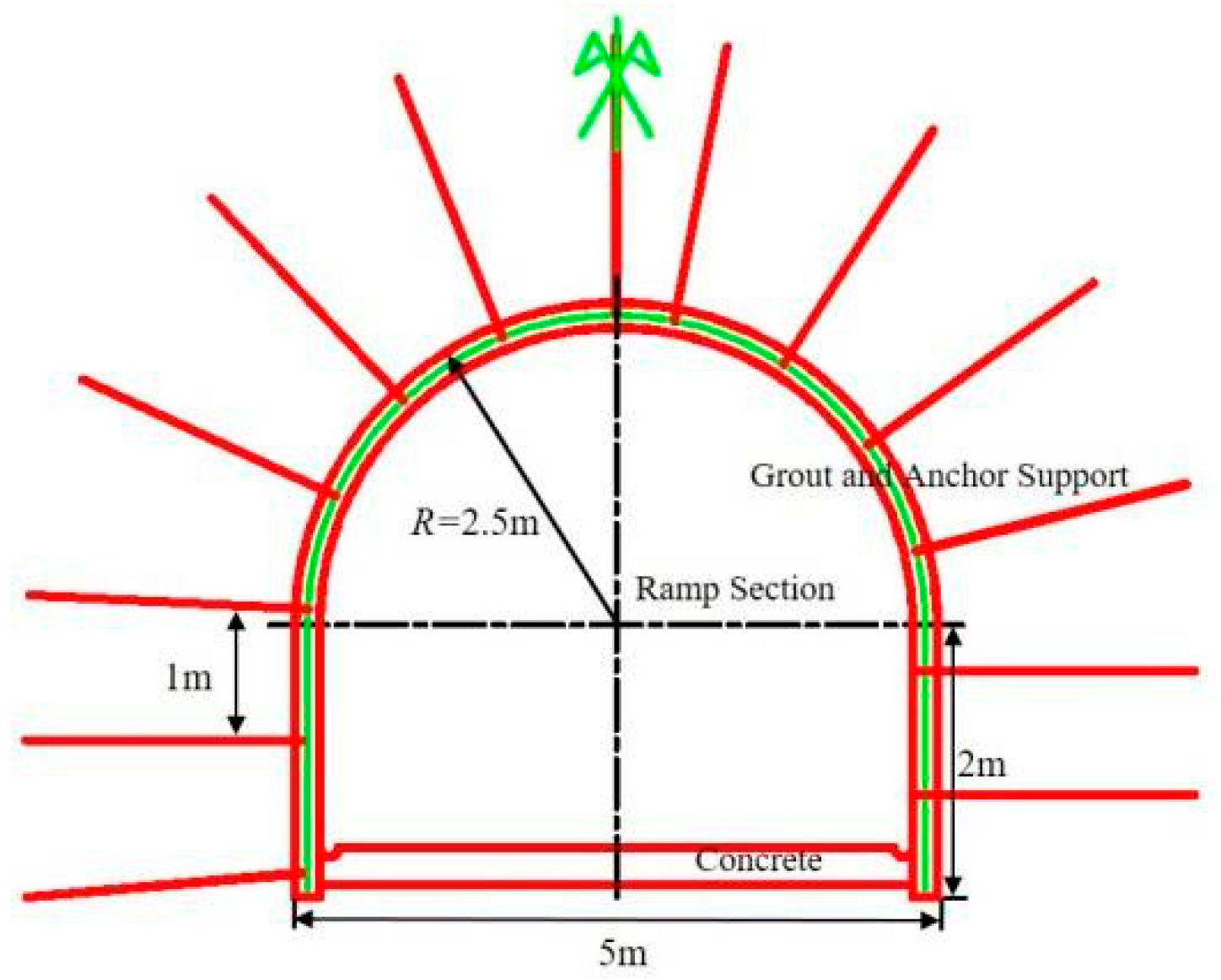
Figure 1. Support parameters of development roadways.
Applsci 15 09950 g001
Figure 2. Roadway development engineering and in situ stress distribution in Jinchuan II Mining Area: (a) roadway development engineering; (b) in situ stress distribution.
Applsci 15 09950 g002
Figure 3. Testing of rocks mechanical parameters: (a) uniaxial compression tests; (b) Brazilian splitting tests; (c) variable-angle shear tests.
Applsci 15 09950 g003
Figure 4. Construction of numerical model.
Applsci 15 09950 g004
Figure 5. Determination of deep roadway surrounding rock parameters based on RockData 3.0 software.
Applsci 15 09950 g005
Figure 6. Layout of monitoring points for surrounding rock of deep roadways.
Applsci 15 09950 g006
Figure 7. Monitoring of surrounding rock deformation in deep roadways: (a) numerical simulation results; (b) field monitoring results.
Applsci 15 09950 g007
Figure 8. Schematic diagram of principal stress rotation in surrounding rock of deep roadways.
Applsci 15 09950 g008
Figure 9. Schematic diagram of rotation dip angle and azimuth angle of principal stress in surrounding rock of deep roadways.
Applsci 15 09950 g009
Figure 10. Variation process of principal stress magnitude at different monitoring points in surrounding rock of deep roadways: (a) roof surrounding rock; (b) floor surrounding rock; (c) sidewall surrounding rock.
Applsci 15 09950 g010
Figure 11. Evolution law of principal stress direction at different monitoring points in the surrounding rock of deep roadways: (a) roof surrounding rock; (b) floor surrounding rock; (c) sidewall surrounding rock.
Applsci 15 09950 g011
Figure 12. Mining-induced stress rotation trajectories of deep roadway surrounding rock: (a) maximum principal stress; (b) intermediate principal stress; (c) minimum principal stress.
Applsci 15 09950 g012aApplsci 15 09950 g012b
Figure 13. Schematic diagram of principal stress direction rotation in deep roadway surrounding rock.
Applsci 15 09950 g013
Figure 14. Determination of the sensitive area for principal stress direction in deep roadway surrounding rock.
Applsci 15 09950 g014
Figure 15. Influence of mining-induced stress rotation trajectory on the stability of deep roadway surrounding rock: (a) determination of the angle Φ; (b) determination of the dominant joints–fissures group; (c) random distribution of joints and fissures.
Applsci 15 09950 g015
Figure 16. Distribution of plastic zones in deep roadway surrounding rock under different support methods.
Applsci 15 09950 g016
Table 1. Basic mechanical parameters of rocks in deep roadways.
Lithologyσc (MPa)σt (MPa)Cohesion (MPa)Friction Angle (°)Elastic Modulus (GPa)Poisson’s RatioDensity (g/cm3)
Diorite67.226.1919.7435.726.30.362.84
Table 2. Basic mechanical parameters of surrounding rock in deep roadways.
LithologyCohesion (MPa)Friction Angle (°)Elastic Modulus (GPa)Poisson’s RatioTension Strength (MPa)
Diorite2.331.82.630.321.17
Table 3. The parameters of the anchor structural elements.
Structural TypeYong Modulus (GPa)Poisson’s RatioCross-Sectional Area (m2)Yield Tension (GPa)Grout Cohesion (GPa)
Anchor73.90.216 × 10−35.121.75
Disclaimer/Publisher’s Note: The statements, opinions and data contained in all publications are solely those of the individual author(s) and contributor(s) and not of MDPI and/or the editor(s). MDPI and/or the editor(s) disclaim responsibility for any injury to people or property resulting from any ideas, methods, instructions or products referred to in the content.