Locations of Non-Cooperative Targets Based on Binocular Vision Intersection and Its Error Analysis
Abstract
1. Introduction
2. Establishment of Target Location Model
2.1. Establishment of Coordinate System and Definition of Internal and External Orientation Elements
2.1.1. Camera Coordinate System
2.1.2. POS Measurement Coordinate System
2.1.3. POS Navigation Coordinate System
2.2. Establishment of Coordinate Systems Transformation Relations
2.2.1. Transformation Between POS Measurement Coordinate System and Camera Coordinate System
2.2.2. Transformation Between POS Navigation Coordinate System and POS Measurement Coordinate System
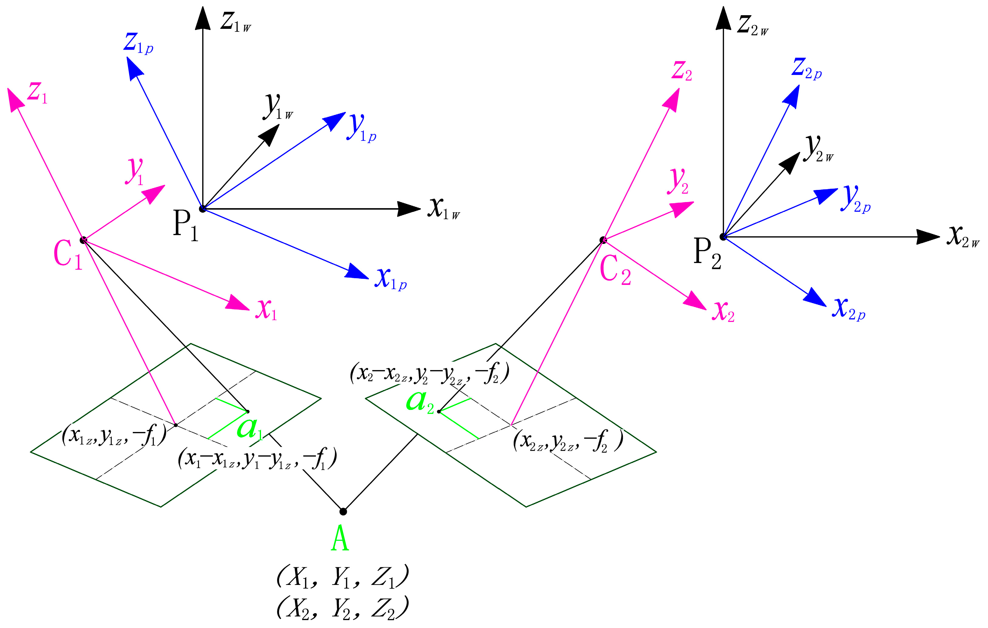
3. Principle of Forward Intersection of Binocular Vision
4. Analysis and Estimation of Location Error
4.1. Analysis of Location Error
4.2. Estimation of Location Error
- , , and the location errors of P1—the measurement center of POS 1—are caused by the errors of the position measurement system (such as the GPS of POS 1). and are taken to be 3 m, and is taken to be 5 m.
- : The elevation difference between camera 1 and target A is represented by . When calculating the location error, is taken to be 2000 m, 3000 m, and 5000 m, respectively.
- , , and : The IMU drift error is a random error, which cannot be corrected and will bring a large target location error. When calculating the target location error, the main error source of the errors of the attitude angles measurement , , and is the IMU drift error. The measurement errors for the heading, pitch, and roll angles can be estimated based on the specification of the IMU of the POS. In the target location method, the real-time measurement accuracy of the IMU and the calibration accuracy of the IMU installation are considered comprehensively; the heading angle measurement error is taken to be 0.08° and the pitch angle measurement error and the roll angle measurement error are both taken to be 0.04°.
- , , and : for camera photography imaging, the average values of the angles between its principal ray and the three coordinate axes of the POS 1 navigation coordinate system is 45°, and the three posture angles-heading angle , pitch angle , and roll angle —are all set to be 45° when calculating the location accuracy.
- and : The focal length of the camera 1 is represented by , and the value of is 129.4 mm. The calibration error of the focal length is represented by, and the value of is 9 µm.
- and : In the image 1 coordinate system, the coordinate values of image point are and . Based on the size of the photosensitive surface of the imaging detector, the maximum value of is determined to be 8.3 mm, and is determined to be 7 mm.
- and : The measurement errors of image point are represented by and , and their generation stem from factors such as image distortion and target identification errors. The distortion of the camera optical lens is less than 0.4%, and after the image is processed by the distortion correction software, the distortion of the final image is less than 0.1%. The main error sources of the measurement errors of the image point are the misidentification and errors in image registration. and are determined to all be 26 µm (4 pixels) after comprehensive consideration.
- and : The calibration errors of the main point of the internal orientation elements are represented by and , which are determined to all be 3 µm.
5. Verification Experiment of Target Location Based on Binocular Vision
5.1. Coordinate Extraction of the Image Point
5.1.1. Coordinate Extraction of the Image Point in Image 1
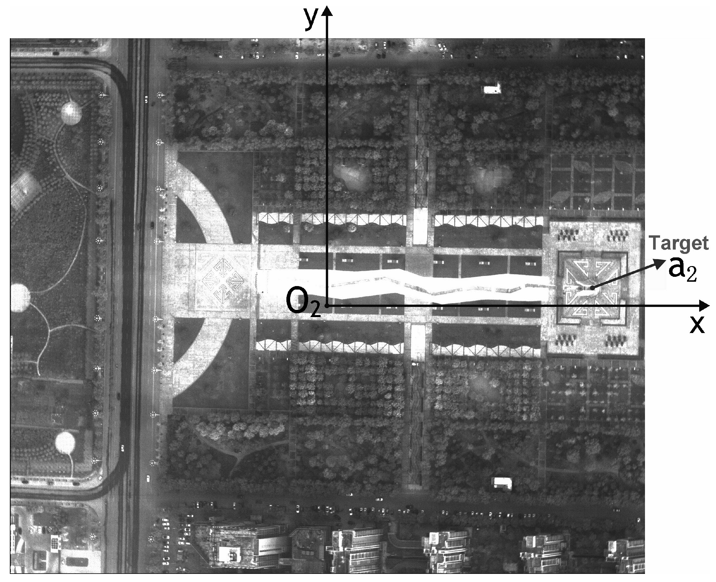
5.1.2. Coordinate Extraction of the Image Point in Image 2
5.2. Calculation of Target Coordinate
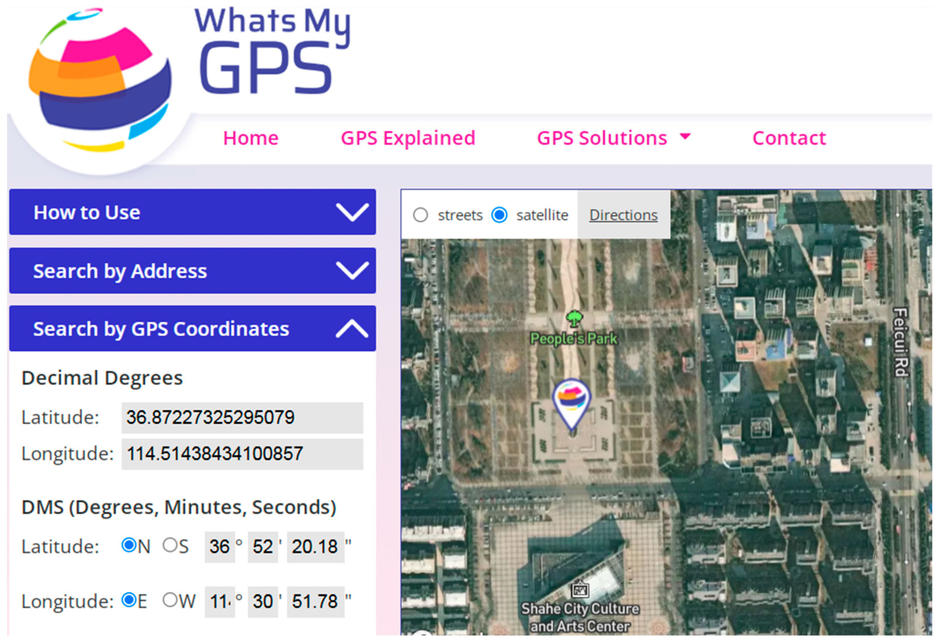
5.3. Calculation of the Latitude and Longitude of Target
5.4. Calculation of the Target Location Error in Experiment
5.5. Analysis of the Target Location Experiment Result
6. Conclusions
Author Contributions
Funding
Institutional Review Board Statement
Informed Consent Statement
Data Availability Statement
Conflicts of Interest
Abbreviations
| POS | Position and Orientation System |
| GPS | Global Positioning System |
| IMU | Inertial Measurement Unit |
| ECEF | Earth-Centered Earth-Fixed |
References
- Santana, B.; Cherif, E.; Bernardino, A.; Ribeiro, R. Real-Time Georeferencing of Fire Front Aerial Images Using Iterative Ray-Tracing and the Bearings-Range Extended Kalman Filter. Sensors 2022, 22, 1150. [Google Scholar] [CrossRef] [PubMed]
- Li, S.; Yoon, H. Vehicle Localization in 3D World Coordinates Using Single Camera at Traffic Intersection. Sensors 2023, 23, 3661. [Google Scholar] [CrossRef]
- Liu, C.; Cui, X.; Guo, L.; Wu, L.; Tang, X.; Liu, S.; Yuan, D.; Wang, X. Satellite Laser Altimetry Data-Supported High-Accuracy Mapping of GF-7 Stereo Images. Remote Sens. 2022, 14, 5868. [Google Scholar] [CrossRef]
- Yang, B.; Ali, F.; Zhou, B.; Li, S.; Yu, Y.; Yang, T.; Liu, X.; Liang, Z.; Zhang, K. A Novel Approach of Efficient 3D Reconstruction for Real Scene Using Unmanned Aerial Vehicle Oblique Photogrammetry with Five Cameras. Comput. Electr. Eng. 2022, 99, 107804. [Google Scholar] [CrossRef]
- Wang, J.; Choi, W.; Diaz, J.; Trott, C. The 3D Position Estimation and Tracking of a Surface Vehicle Using a Mono-Camera and Machine Learning. Electronics 2022, 11, 2141. [Google Scholar] [CrossRef]
- Shao, X.; Tao, J. Location Method of Static Object based on Monocular Vision. Acta Photonica Sin. 2016, 45, 1012003. [Google Scholar]
- Wang, T.; Zhang, Y.; Zhang, Y.; Yu, Y.; Li, L.; Liu, S.; Zhao, X.; Zhang, Z.; Wang, L. A Quadrifocal Tensor SFM Photogrammetry Positioning and Calibration Technique for HOFS Aerial Sensors. Remote Sens. 2022, 14, 3521. [Google Scholar] [CrossRef]
- Liu, Z.; Zhang, X.; Kuang, H.; Li, Q.; Qiao, C. Target Location Based on Stereo Imaging of Airborne Electro-Optical Camera. Acta Opt. Sin. 2019, 39, 1112003. [Google Scholar] [CrossRef]
- Sun, H.; Jia, H.; Wang, L.; Xu, F.; Liu, J. Systematic Error Correction for Geo-Location of Airborne Optoelectronic Platforms. Appl. Sci. 2021, 11, 11067. [Google Scholar] [CrossRef]
- Taghavi, E.; Song, D.; Tharmarasa, R.; Kirubarajan, T. Geo-registration and Geo-location Using Two Airborne Video Sensors. IEEE Trans. Aerosp. Electron. Syst. 2020, 56, 2910–2921. [Google Scholar] [CrossRef]
- Liu, C.; Ding, Y.; Zhang, H.; Xiu, J.; Kuang, H. Improving Target Geolocation Accuracy with Multi-View Aerial Images in Long-Range Oblique Photography. Drones 2024, 8, 177. [Google Scholar] [CrossRef]
- Zhang, X.; Yuan, G.; Zhang, H.; Qiao, C.; Liu, Z.; Ding, Y.; Liu, C. Precise Target Geo-Location of Long-Range Oblique Reconnaissance System for UAVs. Sensors 2022, 22, 1903. [Google Scholar] [CrossRef]
- Yang, B.; Ali, F.; Yin, P.; Yang, T.; Yu, Y.; Li, S.; Liu, X. Approaches for Exploration of Improving Multi-slice Mapping via Forwarding Intersection Based on Images of UAV Oblique Photogrammetry. Comput. Electr. Eng. 2021, 92, 107135. [Google Scholar] [CrossRef]
- Wang, X.; Liu, J.; Zhou, Q. Real-Time Multi-Target Localization from Unmanned Aerial Vehicles. Sensors 2017, 17, 33. [Google Scholar] [CrossRef] [PubMed]
- Yuan, D.; Ding, Y.; Yuan, G.; Li, F.; Zhang, J.; Wang, Y.; Zhang, L. Two-step Calibration Method for Extrinsic Parameters of an Airborne Camera. Appl. Opt. 2021, 60, 1387–1398. [Google Scholar] [CrossRef] [PubMed]
- Cai, Y.; Zhou, Y.; Zhang, H.; Xia, Y.; Qiao, P.; Zhao, J. Review of Target Geo-Location Algorithms for Aerial Remote Sensing Cameras without Control Points. Appl. Sci. 2022, 12, 12689. [Google Scholar] [CrossRef]
- Xu, C.; Huang, D.; Liu, J. Target location of unmanned aerial vehicles based on the electro-optical stabilization and tracking platform. Measurement 2019, 147, 106848. [Google Scholar] [CrossRef]
- Mu, S.; Qiao, C. Ground-Target Geo-Location Method Based on Extended Kalman Filtering for Small-Scale Airborne Electro-Optical Platform. Acta Opt. Sin. 2019, 39, 0528001. [Google Scholar]
- Zhang, G.; Xu, K.; Jia, P.; Hao, X.; Li, D. Integrating Stereo Images and Laser Altimeter Data of the ZY3-02 Satellite for Improved Earth Topographic Modeling. Remote Sens. 2019, 11, 2453. [Google Scholar] [CrossRef]
- Li, B.; Ding, Y.; Xiu, J.; Li, J.; Qiao, C. System error corrected ground target geo-location method for long-distance aviation imaging with large inclination angle. Opt. Precis. Eng. 2020, 28, 1265–1274. [Google Scholar]
- Skibicki, J.; Jedrzejczyk, A.; Dzwonkowski, A. The Influence of Camera and Optical System Parameters on the Uncertainty of Object Location Measurement in Vision Systems. Sensors 2020, 20, 5433. [Google Scholar] [CrossRef] [PubMed]
- Chen, Y.; Luo, L.; Jin, W.; Guo, H.; Zhao, S.; Yang, J. Target positioning method for Tian-shaped four-aperture infrared biomimetic compound eyes. Opt. Precis. Eng. 2024, 32, 1836–1848. [Google Scholar] [CrossRef]
- Qiao, C.; Ding, Y.; Xu, Y.; Xiu, J.; Du, Y. Ground target geo-location using imaging aerial camera with large inclined angles. Opt. Precis. Eng. 2017, 25, 1714–1726. [Google Scholar]
- Li, Z.; Kuang, H.; Zhang, H.; Zhuang, C. A target location method for aerial images through fast iteration of elevation based on DEM. Chin. Opt. 2023, 16, 777–787. [Google Scholar] [CrossRef]
- Bai, G.; Liu, J.; Song, Y.; Zuo, Y. Two-UAV Intersection Localization System Based on the Airborne Optoelectronic Platform. Sensors 2017, 17, 98. [Google Scholar] [CrossRef]
- Yao, Y.; Song, C.; Shao, J. Real-time Detection and Localization Algorithm for Military Vehicles in Drone Aerial Photography. Acta Armamentarii 2024, 45, 354–360. [Google Scholar]


| HA − H1 | 2000 | 3000 | 5000 | |||
|---|---|---|---|---|---|---|
| x1w | y1w | x1w | y1w | x1w | y1w | |
| 3 | 0 | 3 | 0 | 3 | 0 | |
| 0 | 3 | 0 | 3 | 0 | 3 | |
| 6.13 | 10.12 | 6.13 | 10.12 | 6.13 | 10.12 | |
| 0.73 | 0.54 | 1.10 | 0.81 | 1.83 | 1.36 | |
| 2.85 | 2.41 | 4.28 | 3.61 | 7.13 | 6.01 | |
| 0.04 | 4.17 | 0.06 | 6.25 | 0.09 | 10.42 | |
| 0 | 0.04 | 0.01 | 0.06 | 0.01 | 0.10 | |
| 0.90 | 1.71 | 1.35 | 2.57 | 2.25 | 4.28 | |
| 0.88 | 0.22 | 1.33 | 0.34 | 2.21 | 0.56 | |
| 0.10 | 0.20 | 0.16 | 0.30 | 0.26 | 0.49 | |
| 0.10 | 0.03 | 0.15 | 0.04 | 0.25 | 0.06 | |
| 7.54 | 11.75 | 8.35 | 13.08 | 10.52 | 16.64 | |
| 14.0 | 15.5 | 19.7 | ||||
| Parameters | Values |
|---|---|
| Detector pixel | 2560 (H 1) × 2160 (V 2) |
| Pixel size | 6.5 μm × 6.5 μm |
| Size of the photosensitive surface | 16.64 mm × 14.04 mm |
Disclaimer/Publisher’s Note: The statements, opinions and data contained in all publications are solely those of the individual author(s) and contributor(s) and not of MDPI and/or the editor(s). MDPI and/or the editor(s) disclaim responsibility for any injury to people or property resulting from any ideas, methods, instructions or products referred to in the content. |
© 2025 by the authors. Licensee MDPI, Basel, Switzerland. This article is an open access article distributed under the terms and conditions of the Creative Commons Attribution (CC BY) license (https://creativecommons.org/licenses/by/4.0/).
Share and Cite
Shi, K.; Yang, H.; Feng, J.; Liu, G.; Chen, W. Locations of Non-Cooperative Targets Based on Binocular Vision Intersection and Its Error Analysis. Appl. Sci. 2025, 15, 9867. https://doi.org/10.3390/app15189867
Shi K, Yang H, Feng J, Liu G, Chen W. Locations of Non-Cooperative Targets Based on Binocular Vision Intersection and Its Error Analysis. Applied Sciences. 2025; 15(18):9867. https://doi.org/10.3390/app15189867
Chicago/Turabian StyleShi, Kui, Hongtao Yang, Jia Feng, Guangsen Liu, and Weining Chen. 2025. "Locations of Non-Cooperative Targets Based on Binocular Vision Intersection and Its Error Analysis" Applied Sciences 15, no. 18: 9867. https://doi.org/10.3390/app15189867
APA StyleShi, K., Yang, H., Feng, J., Liu, G., & Chen, W. (2025). Locations of Non-Cooperative Targets Based on Binocular Vision Intersection and Its Error Analysis. Applied Sciences, 15(18), 9867. https://doi.org/10.3390/app15189867


