Abstract
A PWM-based rotor position and speed estimator is presented in this study. The method is based on the measurement of the current response to conventional space vector pulse width-modulated voltage (SV-PWM) for PMSM drive applications. Model reference adaptive system (MRAS) estimators are often used for sensorless speed estimation. A MRAS typically uses two models: the reference model (voltage model) and the adaptive model (current model). The voltage model in flux-based MRAS uses the integration of stator voltages to calculate the stator flux. The pure integrator is usually replaced by a low-pass filter; however, this results in phase errors at low frequencies. The position is estimated using oversampling and averaging over a switching SV-PWM cycle, eliminating the need for integrators. Extensive experimental tests are presented to evaluate the performance of the PWM-based estimator. The results of the experiments demonstrate good performance at various speeds and under various load circumstances, in both motoring and regenerating modes. The proposed method also shows robustness to changes in motor parameters.
1. Introduction
Permanent magnet synchronous machines (PMSMs) are increasingly adopted in both industrial and high-performance applications, such as electric vehicle traction, due to their high efficiency, high power density, and relatively simple structure [1]. Field-oriented control is commonly employed to achieve high accuracy and rapid dynamic responses [2]. However, this strategy requires accurate rotor position information, which is typically obtained from encoders or resolvers. In low-cost applications, these sensors add undesired complexity, wiring, and cost, while in high-performance systems such as electric vehicles, sensor reliability remains a critical challenge. Consequently, sensorless control methods have attracted significant attention both as low-cost alternatives and as backup strategies to enhance drive reliability.
A variety of sensorless techniques have been developed over the years. Observer-based methods, including extended Kalman filters, sliding-mode observers, fuzzy logic, and artificial neural networks, offer robustness against measurement noise and parameter variations but often require heavy computation and may suffer from instability at low speeds [3,4,5,6,7,8]. Signal injection techniques exploit motor saliency to estimate rotor position at zero and very low speeds, yet they introduce torque ripple, audible noise, and additional hardware requirements, limiting their applicability in traction and industrial systems [9].
Among these approaches, model reference adaptive system (MRAS) estimators have gained widespread popularity for their simplicity and relatively low computational demands [10,11,12]. MRAS methods are generally derived from back-EMF voltage models and provide satisfactory performance at medium and high speeds [13]. However, their reliance on integrators in the voltage model introduces offsets, drift, and sensitivity to parameter variations. While low-pass filters have been used to mitigate these issues, they often cause phase delays, reduce bandwidth, and increase tuning complexity [14,15,16]. Solutions such as programmable filters, modified integration algorithms, and fuzzy-augmented designs can improve performance in some cases, but they still rely on filters or complex computations, and may exhibit instability during speed reversals [17,18,19,20]. Higher-order observers, such as generalized integrator-based flux observers and Active Disturbance Rejection Control (ADRC) schemes, have also shown enhanced robustness, yet their implementation complexity can be prohibitive for real-time embedded systems [21,22,23]. More recently, [24] introduced a stator feed-forward voltage estimation MRAS method that improves low-speed performance, while [25] analyzed stator-current-based MRAS with sensitivity adaptation to enhance robustness under parameter variations. These applications demonstrate progress towards reliable low-speed sensorless operation but still depend on integrators or require careful filter tuning. Also, [26] proposed an extended-flux (EF) model-based PI observer that uses derivatives of extended-flux components to estimate rotor position, with LQR-tuned PI gains employed to mitigate the noise amplification inherent in differentiation. While this approach achieves accurate low-speed estimation and robustness to load variations, it depends on precise machine parameters, and involves higher computational complexity.
Despite these advances, a key research gap remains in achieving accurate, low-speed, and integrator-independent MRAS estimation without relying on filters that introduce phase delay, bandwidth reduction, instability, or additional implementation complexity. In addition, the reliance on complex tuning procedures and heavy computational requirements further increases implementation complexity, reducing their practicality for real-time and cost-sensitive applications.
To address these challenges, this paper introduces a PWM-based MRAS estimator for PMSM drives. Unlike classical flux-based MRAS, which relies on pure integrators or LPFs, the proposed approach eliminates the integrator by exploiting the PWM duty-cycle information in the voltage model. This results in an integrator-independent reference model that avoids phase-lag issues and ensures accurate estimation at low speeds. The approach builds on earlier PWM-aided estimation concepts [27] but introduces a formulation based on the d-axis voltage equation, enabling reliable rotor speed and position estimation under parameter variations. The proposed method is validated through extensive experiments, demonstrating improved low-speed performance, robustness under parameter uncertainties, low computational complexity, and stable operation across all four quadrants, thus addressing the limitations of existing MRAS-based techniques.
2. Control and Estimation
2.1. Machine Model
The voltage equations of a PMSM represented in the rotating dq-reference frame are expressed as follows [11]:
where , , , and are dq-axis voltages and currents, respectively; and are the dq-axis inductances, is the stator resistance, is the rotor speed, and is the rotor PM flux linkage.
2.2. Classical Flux-Based MRAS Speed Estimator
The classical MRAS speed estimation compares estimated stator flux linkage based on integrating back emf (3), with stator flux linkage from magnet flux and current (4) [11].
Equation (4) is transformed into the stationary reference frame by using the Clarke to Park transform as follows:
where , , , and are the estimated flux components for the voltage and current models, respectively; , , , and are voltages and currents in the stationary α, β reference frame; and are the currents in the estimated dq-rotating frame; and is the estimated rotor position.
The estimated speed is obtained by minimizing the angle error between the two stator flux linkages vectors estimations. This can be achieved by calculating the magnitude of the cross product of the two estimated fluxes as follows:
The error in Equation (6) is then fed to a PI controller to produce an estimation of rotor speed, which is integrated to obtain the estimated position. As shown in Figure 1, the position is fed back to the current model to drive the error to zero.
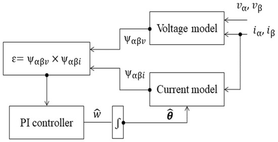
Figure 1.
Block diagram of the classical flux-based MRAS estimator.
2.3. PWM-Based Speed Estimator
Equation (1) can be represented in the estimated rotating dq-reference frame as follows:
where , , and are the estimated dq-axis voltages and currents, respectively; is the estimated rotor speed, and is the flux on the estimated q-axis.
Figure 2 shows the simulation of three PWM gate signals, each with a period of 500 μs controlling the top three transistors in a two-stage voltage source inverter. It also shows the corresponding and , sampled at 50 μs.
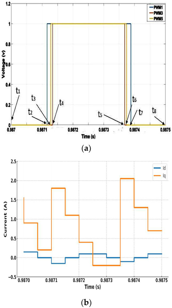
Figure 2.
PWM signals and d–q currents in one switching period: (a) PWM signals, (b) d–q currents.
Assuming that … (shown in Figure 2) are the time instants at which a different voltage vector is applied and is the constant during one switching period, Equation (7) is discretized with a sampling time . The resultant relationships between two adjacent sampling points are given as follows:
where n is the integer number of sampling points in one switching cycle, is the starting point of the PWM period, and is the last sampling point in the period.
The derivative term can be approximated by
Multiplying the n − 1 equations by and adding each equation to the next yields:
where , with as the switching frequency, k = 0, 1, …, n − 2, and as the th equation.
According to [27], the sum is equivalent to the average PWM voltage:
where , , , and are the results of the switching vectors being transformed from the αβ reference frame to estimated dq-rotating reference frame.
As the switching period consists of two symmetrical switching combinations, it can be easily verified that
Therefore, after rearranging Equation (11) to get this now becomes
The rotating voltage reference vector’s location on the space vector diagram is used to calculate the average PWM voltage at the beginning of a PWM switching period; hence, the reference voltage on αβ stationary frame (, ) should take the form of a rotating space vector.
The actual reference magnet fluxes in the real dq-rotating frame are represented as and 0. the estimated flux on the estimated -axis, is proportional to the sine of the angle estimation error. Figure 3 shows the simulation result of . The vector product ϵ of the flux components, shown in Equation (16), is fed into a PI controller, which produces the estimated speed. Finally, the integration of the speed gives the estimated position, as shown in Figure 4.
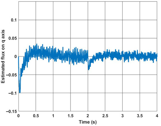
Figure 3.
Simulation of , with speed changes from 40 to 100 rad/s at 2 s under load of 3 Nm.
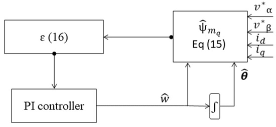
Figure 4.
Block diagram of the PWM-based estimator.
For vector controlled PMSM drive (), Equation (15) can be simplified as follows:
For comparison, the execution time on the Speedgoat real-time system (1.99 GHz) is approximately 1 µs for the proposed PWM-based method and 0.7 µs for the classical method when using the optimized fast math library. On a representative low-cost controller such as the TI C2000 DSP (150 MHz), the estimated execution times are about 13 µs and 9 µs, respectively.
3. Simulation Results
The PWM-based method was tested for various conditions by using MATLAB/Simulink R2021a. It was assumed that neither the inverter nonlinearity nor the dead-time effects were considered. The motor parameters are shown in Table 1. In Figure 5, the machine is tested at 50 rad/s under rated torque. The torque is initially set to 0 Nm and then set to the rated value at 1 s. Figure 5b shows that the position error negligibly increases from 0 to about 0.02 rad at rated torque. Figure 6 shows the simulation result of the performance of the PWM-based method at a low speed, where the reference speed is set to 3 rad/s and then changed to 1 rad/s at time 1 s, as seen in Figure 6a. From Figure 6b, it can be seen that the position accuracy is not affected at low speeds as expected and the error is nearly zero. A simulation was performed under fast-speed ramp conditions to examine dynamics, as seen in Figure 7; it may introduce inaccuracies during rapid transients. Although a slight deviation in position accuracy is observed during the transient, the estimator rapidly converges, indicating that the assumption remains acceptable.

Table 1.
Machine and control parameters.
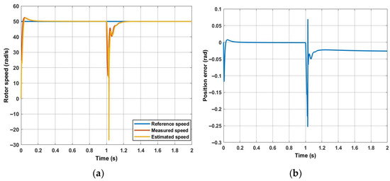
Figure 5.
PWM-based MRAS is tested at 50 rad/s under rated torque: (a) speed; (b) position error.
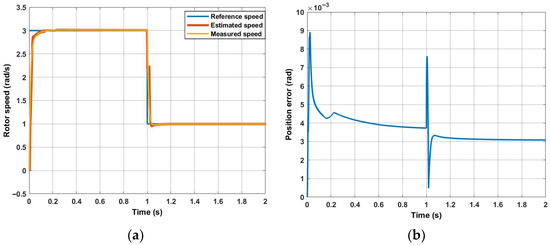
Figure 6.
PWM-based is tested at very low speed under rated torque: (a) speed; (b) position error.
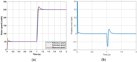
Figure 7.
PWM-based MRAS is tested at step speed: (a) speed; (b) position error.
4. Experimental Setups
The experimental setup (Figure 8) consists of two identical 2.1 kW PMSMs. One dynamometer is connected to a three-phase two-levels inverter (Semikron IGBT module stack) and controlled by a Speedgoat real-time controller. The second Drive Unit is controlled by a Nidec Unidrive 700 M drive. The two motors can be controlled in either speed or torque modes. The motor parameters are presented in Table 1. A 4096 counts/rev resolution quadrature encoder is used to measure the rotor position for verification purposes, and two TA189 current sensors are used for current phase measurements. Position and currents are sampled at 80 μs. The inverter switching frequency is set to 3.125 kHz with a dead time of 0.5 μs. The control strategy (FOC), illustrated in Figure 9 (the switch box is performed manually to compare the performance of the two methods), is executed at a sampling frequency of 80 μs using the Speedgoat real-time controller, which is fully integrated with MATLAB/Simulink. The estimation algorithm is executed using a MATLAB function block, and is triggered at the beginning of each PWM switching period. The choice of a 3.125 kHz switching frequency and 0.5 µs dead time is based on Semikron datasheet specifications, ensuring safe operation without shoot-through, while keeping the dead time short relative to the PWM period (0.16%) to avoid excessive voltage distortion. Consequently, the resulting dead-time voltage error is negligible, minimizing its effect, particularly at low speeds. The 3.125 kHz frequency was also selected to ensure that the ratio between the sampling frequency and the switching frequency was an integer, so that the number of equations within a switching period was consistent. The command voltages generated by the controller are used in place of the measured voltages. Therefore, inverter nonlinearity and dead-time effects are not taken into account. At low speeds, as the effects of inverter nonlinearities are pronounced, the speed oscillation becomes higher so a low-pass filter with a 10 Hz cut-off frequency is used to reduce the oscillation. The PI controller gains of the proposed method are set to 500 and 2000, whereas the classical method employs gains of 200 and 2000. The trial-and-error approach is employed for tuning the gains to achieve the best possible performance for each method in terms of stability, convergence speed, and estimation accuracy. The current and speed control loop bandwidths are 318 Hz and 2 Hz, respectively. A first-order LPF with a 3 Hz cut-off frequency is used in the classical method instead of the integrator to minimize drift and initial condition problems. However, it causes a position error of about 0.3 rad at 3 Hz. The trade-off between angle error and filtering is used as a design criterion.
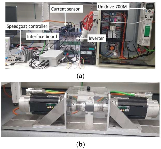
Figure 8.
Experimental test rig: (a) the experimental hardware; (b) two identical PMSMs.
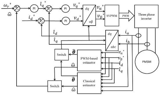
Figure 9.
The block diagram of both sensorless PMSM drives.
5. Experimental Results
To evaluate the comparative performance of the proposed estimator and the classical flux-based MRAS scheme, extensive tests are performed in FOC under position sensorless operation. Both estimators’ performances are evaluated under the condition () and with the same sampling time and switching frequency. As shown in Figure 10, a rotating signal injection method is used for zero speed. This starts as back-EMF is unobservable at zero speed for both the conventional technique and the proposed method, and this could explain the discrepancies observed in the transient response between the measured speed and the estimated speed (time interval 0–0.25 s). The injection frequency and amplitude of the injected voltage are 40 volts and 400 Hz, respectively. Figure 10 shows that the drive operates smoothly during the gradual transition from the injection method to the proposed method at 3 s. A blending strategy was used to transition from the startup injection method to the proposed method to ensure a smooth and seamless switch while minimizing transient effects. The position error by the injection method is driven to zero once the proposed method is activated, as shown in Figure 10b.
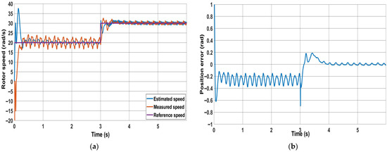
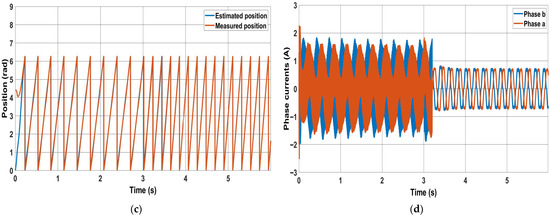
Figure 10.
Injection method combined with the PWM method: (a) speed response; (b) position error; (c) measured and estimated position for the new method; (d) phase currents.
In Figure 11 and Figure 12, the performance of the novel and the classical methods are tested at low speeds with no load. From Figure 11a and Figure 12a, it is clearly shown that the speed oscillation is higher for the classical method compared to the proposed method. Moreover, Figure 11b shows that as the speed decreases, the position accuracy in the steady period is nearly not affected in the proposed method, but the error increases in the classical MRAS until it fails at a speed of 10 rad/s as shown in Figure 12b. The loss of control occurs because the estimated currents and deviate from their reference’s values and . This deviation occurs as the position error increases significantly. This is clearly noticed from Figure 11d and Figure 12d, which show the phase currents for the two methods. It is evident from Figure 11d that the phase currents are not affected when switching from the sensored mode to sensorless mode at 5 s using the proposed method, and the current decreases as the speed decreases. In contrast, the classical method produces larger currents due to a higher position error.
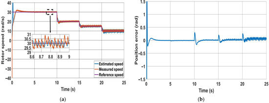
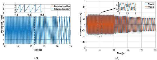
Figure 11.
PWM method performance at low speeds: (a) speed; (b) position error; (c) rotor positions; (d) phase currents.
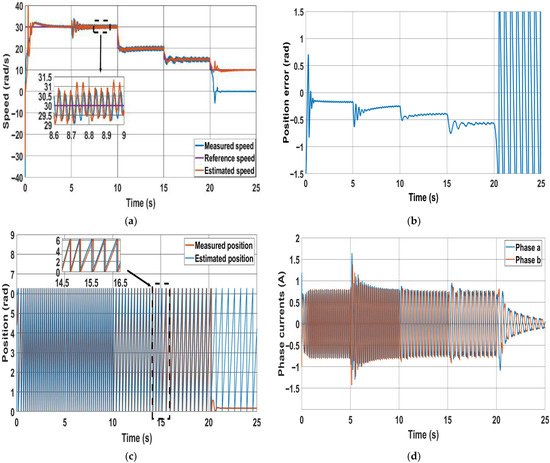
Figure 12.
Classical method at 30 rad/s, 20 rad/s, 15 rad/s and 10 rad/s: (a) speed response; (b) position error; (c) estimated and measured positions; (d) phase currents.
Both methods are tested in motoring and regenerative modes, as illustrated in Figure 13 and Figure 14, respectively. Initially, the reference speed is set to 50 rad/s with 20% of the rated torque applied, which is then increased to 40% of the rated torque. In the motoring mode (Figure 13), it is clear that both the speed ripples and the position error during the steady state are smaller for the new method compared to the classical method. However, during the transient period, both speed and position errors generated by the new method are slightly higher than those produced by the classical method. The performance of the PWM-based method can be enhanced beyond that of the classical method during the transient period. This can be achieved by further tuning the PI gain of the estimator used in the new method. In the regenerative mode (Figure 14), the classical method shows higher-speed ripples than the PWM-based method in both steady-state and transient periods. Concerning position error, it is evident that as the load increases, nearly + 0.05 rad is added to the error for every 20% increase in rated torque for both methods, as illustrated in Figure 14b,d.
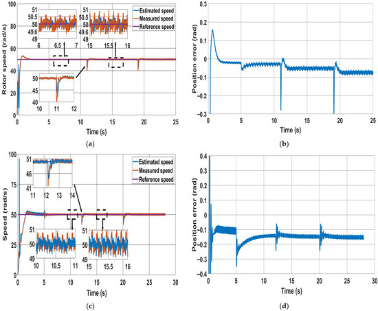
Figure 13.
Motoring mode at 20% and 40% of rated torque: (a) speed response for the PWM-based method; (b) position error for PWM-based method; (c) speed response for the classical method; (d) position error for the classical method.
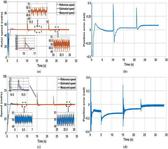
Figure 14.
Sensorless operation with regenerative mode at 20% and 40% of rated torque: (a) speed response for the PWM-based; (b) corresponding position error for the PWM-based; (c) speed response for the classical MRAS; (d) position error for the classical MRAS.
To test the proposed scheme’s robustness against motor parameter variations and compare it with the classical method, two experimental tests have been carried out. In the first test, (Figure 15), the sensorless mode occurs at 2 s and a change of 50% is applied to the stator resistance in the estimator models at 5 s; it is then further increased to 100% at 8 s. In the second test, (Figure 16), Lq in the estimator models changes by 20% at 5 s, followed by an increase to 40% at 8 s. It can be observed that the PWM-based method shows robustness against motor parameter variations. This can be noted by comparing both the speed error and the position error produced by the PWM-based method before and after the changes, as shown in Figure 15 and Figure 16. These show that both the position error and speed ripples are not affected. In contrast, in the classical method, the speed oscillation increases as the resistance rises, though it is less sensitive to changes in Lq. It is clear from Equation (3) that the stator flux linkage, obtained from stator voltage integration, is dependent on the value of stator resistance. The proposed method, instead, is based on the estimation of the q-axis magnet flux, which is independent of the stator resistance, as given by Equation (17). Therefore, we can conclude that the proposed method is, in principle, insensitive to stator resistance.
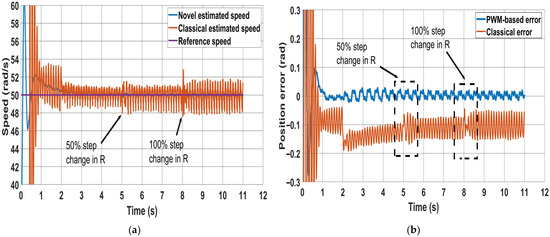
Figure 15.
Effect of stator resistance change on both methods (50% and 100% step changes): (a) speed response; (b) position error.
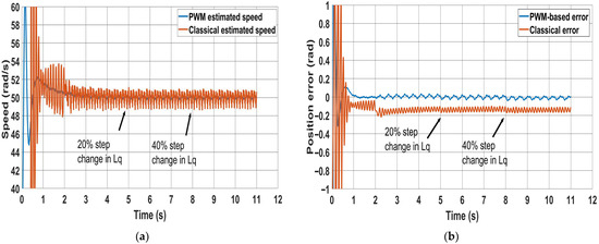
Figure 16.
Effect of q-inductance change on both methods (20% and 40% step changes): (a) speed error; (b) corresponding position error.
Table 2 presents a comparative experimental analysis between the classical flux-based MRAS and the proposed PWM-based MRAS under identical test conditions. The results clearly show that the proposed method provides superior estimation accuracy and robustness, particularly at low speeds. For instance, at 30 rad/s, the peak position error with the classical MRAS is 0.2 rad, whereas the proposed PWM-based MRAS reduces it to only 0.02 rad. Similarly, at 50 rad/s no load, the error decreases from 0.14 rad (classical) to 0.034 rad (proposed). Speed ripple is also consistently reduced: at 30 rad/s, the classical MRAS exhibits 8.3% ripple compared to only 2.67% with the proposed method. In dynamic response tests, both methods achieve similar settling times, but overshoot is substantially lower in regenerative mode with the proposed scheme (20% vs. 40%). Furthermore, while the classical MRAS loses accuracy and fails to operate at 10 rad/s, the PWM-based MRAS maintains stable performance down to speeds lower than 10 rad/s. It is worth mentioning that at very low speeds, the position accuracy of the proposed method remains unaffected; however, the speed ripple increases due to inverter nonlinearities and dead-time effects not being considered. This suggests that compensating for dead time would further enhance low-speed performance. Finally, robustness to parameter mismatch is improved, since changes in stator resistance degrade the classical MRAS, whereas the proposed PWM-based MRAS remains unaffected.

Table 2.
Consolidated quantitative performance metrics of the two methods.
The performance of the PWM-based method is also tested for ≠ 0 to investigate the effect of canceling the voltage terms and in Equation (7) on the position accuracy. Figure 17 shows the position error resulting from setting the d-axis current reference to nonzero values. In the test, the d-axis current reference is set to 0.5 A and 1 A at 7 s and 10 s, respectively. The implementation of Equation (17) shows that the accuracy of the position experiences only a slight decrease compared to the compensated error arising from the use of Equation (15), where all voltage terms are fully considered.
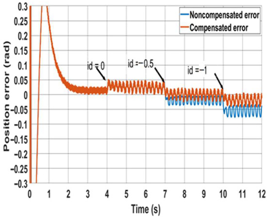
Figure 17.
Effect of nonzero d-axis currents on the estimated position accuracy for the PWM-based method.
6. Conclusions
In this paper, a PWM-based MRAS speed estimator is proposed for sensorless control of PMSM drives. The method uses the oversampling of PWM voltages and currents during a switching cycle. The PWM-based method is proved to perform better than the classical MRAS method, with smaller position errors in most operating conditions. Unlike the classical flux-based MRAS method, the position accuracy is not affected in the PWM-based method at low speeds due to the lack of integrator. The proposed method is also shown to be less sensitive to parameter variation. Compensation for the inverter nonlinearity and dead-time effects can be employed in further research to reduce speed oscillation at very low speeds. It is also recommended to extensively test the performance of this method on PM machines operating in the flux-weakening region, where ≠ 0. Although the stability of the proposed MRAS estimator has been validated through experimental and simulation results under various operations conditions and parameter variations, formal stability proof (e.g., Lyapunov or small-signal analysis) is not provided in this study and is identified as an important topic for future research.
Author Contributions
Conceptualization, A.G.; methodology, S.B.S.; software, S.B.S.; validation, S.B.S.; formal analysis, S.B.S.; investigation, S.B.S.; resources, A.G.; data curation, S.B.S.; writing—original draft preparation, S.B.S.; writing—review and editing, A.G.; visualization, S.B.S.; supervision, A.G.; project administration, A.G. All authors have read and agreed to the published version of the manuscript.
Funding
This research was funded by the Libyan embassy in London, UK. PhD Scholarship.
Institutional Review Board Statement
Not applicable.
Informed Consent Statement
Not applicable.
Data Availability Statement
The data presented in this study are available in the article.
Conflicts of Interest
The authors declare no conflicts of interest.
References
- Krishnan, R. Permanent Magnet Synchronous and Brushless DC Motor Drives; CRC Press: Cleveland, OH, USA, 2017. [Google Scholar]
- Bose, B.K. Power Electronics and Variable Frequency Drives; Wiley: Hoboken, NJ, USA, 1996. [Google Scholar]
- Zuo, Y.; Lai, C.; Iyer, K.L.V. A Review of Sliding Mode Observer Based Sensorless Control Methods for PMSM Drive. IEEE Trans. Power Electron. 2023, 38, 11352–11367. [Google Scholar] [CrossRef]
- Krishna, S.M.; Daya, J.F. MRAS speed estimator with fuzzy and PI stator resistance adaptation for sensorless induction motor drives using RT-lab. Perspect. Sci. 2016, 8, 121–126. [Google Scholar] [CrossRef]
- Maiti, S.; Verma, V.; Chakraborty, C.; Hori, Y. An Adaptive Speed Sensorless Induction Motor Drive with Artificial Neural Network for Stability Enhancement. IEEE Trans. Ind. Inform. 2012, 8, 757–766. [Google Scholar] [CrossRef]
- Matsumoto, A.; Hasegawa, M.; Tomita, M.; Matsui, K. Algebraic design of full-order flux observer for IPMSM position sensorless control. In Proceedings of the IEEE International Electric Machines & Drives Conference (IEMDC), Niagara Falls, ON, Canada, 22 August 2011; pp. 1276–1281. [Google Scholar]
- Lee, K.-G.; Lee, J.-S.; Lee, K.-B. SPMSM sensorless control for wide speed range using full-order flux observer. In Proceedings of the IEEE International Conference on Industrial Technology (ICIT), Busan, Republic of Korea, 26 February–1 March 2014; pp. 164–168. [Google Scholar]
- Xu, Y.; Yao, M.; Sun, X. Overview of Position-Sensorless Technology for Permanent Magnet Synchronous Motor Systems. World Electr. Veh. J. 2023, 14, 212. [Google Scholar] [CrossRef]
- Xu, P.L.; Zhu, Z.Q. Comparison of carrier signal injection methods for sensorless control of PMSM drives. In Proceedings of the IEEE Energy Conversion Congress and Exposition (ECCE), Montreal, QC, Canada, 20–24 September 2015; pp. 5616–5623. [Google Scholar]
- Zhang, Z. Sensorless Back EMF Based Control of Synchronous PM and Reluctance Motor Drives—A Review. IEEE Trans. Power Electron. 2022, 37, 10290–10305. [Google Scholar] [CrossRef]
- Zhang, X.; Bodrov, A.; Apsley, J.; Semjonovs, A.; Zbede, Y. Speed Sensorless Control of a Surface-mounted Permanent Magnet Drive. In Proceedings of the 2019 10th International Conference on Power Electronics and ECCE Asia (ICPE 2019—ECCE Asia), Busan, Republic of Korea, 27–30 May 2019; pp. 2853–2859. [Google Scholar]
- Kumar, R.; Das, S.; Syam, P.; Chattopadhyay, A.K. Review on model reference adaptive system for sensorless vector control of induction motor drives. IET Electr. Power Appl. 2015, 9, 496–511. [Google Scholar] [CrossRef]
- Zhao, Y.; Wei, C.; Zhang, Z.; Qiao, W. A Review on Position/Speed Sensorless Control for Permanent-Magnet Synchronous Machine-Based Wind Energy Conversion Systems. IEEE J. Emerg. Sel. Top. Power Electron. 2013, 1, 203–216. [Google Scholar] [CrossRef]
- Teja, A.R.; Verma, V.; Chakraborty, C. A New Formulation of Reactive-Power-Based Model Reference Adaptive System for Sensorless Induction Motor Drive. IEEE Trans. Ind. Electron. 2015, 62, 6797–6808. [Google Scholar] [CrossRef]
- Karol, W.; Grzegorz, T.; Krzysztof, S.; Seiichiro, K. Improving Regenerating Mode Operation of MRAS-Based Induction Motor Speed Estimation Using the Multilayer Technique. IEEE Access 2024, 12, 153063–153073. [Google Scholar] [CrossRef]
- Zbede, Y.B.; Gadouie, S.M.; Atkinson, D.J. Model Predictive MRAS Estimator for Sensorless Induction Motor Drives. IEEE Trans. Ind. Electron. 2016, 63, 3511–3521. [Google Scholar] [CrossRef]
- Shin, M.H.; Hyun, D.S.; Cho, S.B.; Choe, S.Y. An improved stator flux estimation for speed sensorless stator flux orientation control of induction motors. IEEE Trans. Power Electron. 2000, 15, 312–318. [Google Scholar] [CrossRef]
- Hinkkanen, M.; Luomi, J. Modified integrator for voltage model flux estimation of induction motors. IEEE Trans. Ind. Electron. 2003, 50, 818–820. [Google Scholar] [CrossRef]
- Huang, K.; Li, W.; Huang, S.; Xiao, L.; Zheng, L.; Xu, Z. Sensorless control of direct-driven permanent magnet wind power generation system based on improved MRAS. In Proceedings of the 2011 International Conference on Electrical Machines and Systems, Beijing, China, 20–23 August 2011; pp. 1–5. [Google Scholar]
- Strinić, T.; Silber, S.; Gruber, W. The Flux-Based Sensorless Field-Oriented Control of Permanent Magnet Synchronous Motors without Integrational Drift. Actuators 2018, 7, 35. [Google Scholar] [CrossRef]
- Xu, W.; Jiang, Y.; Mu, C.; Blaabjerg, F. Improved nonlinear flux observer-based second-order soifo for PMSM sensorless control. IEEE Trans. Power Electron. 2019, 34, 565–579. [Google Scholar] [CrossRef]
- Zuo, Y.; Ge, X.; Zheng, Y.; Chen, Y.; Wang, H.; Woldegiorgis, A.T. An Adaptive Active Disturbance Rejection Control Strategy for Speed-Sensorless Induction Motor Drives. IEEE Trans. Transp. Electrif. 2022, 8, 3336–3348. [Google Scholar] [CrossRef]
- Accetta, A.; Cirrincione, M.; Girolamo, S.D.; D’Ippolito, F.; Pucci, M.; Sferlazza, A. Robust Nonlinear Control for Induction Motor Drives Based on Adaptive Disturbance Compensation. IEEE Trans. Ind. Appl. 2025, 61, 3163–3173. [Google Scholar] [CrossRef]
- Pindoriya, R.M.; Tejan, K.V.; Rajpurohit, B.S. Stator feed-forward voltage estimation with MRAS technique for position sensorless PMSM drive. Int. J. Power Electron. 2023, 18, 460–481. [Google Scholar] [CrossRef]
- Zaky, M.S.; Metwaly, M.K. Sensitivity analysis of a stator current-based MRAS estimator for sensorless induction motor drives. Eng. Technol. Appl. Sci. Res. 2024, 14, 17584–17590. [Google Scholar] [CrossRef]
- Salman, E.; Yilmaz, M. A Novel Sensorless Control Approach for IPMSM Using Extended Flux Based PI Observer for Washing Machine Applications. Int. J. Control. Autom. Syst. 2023, 21, 2313–2322. [Google Scholar] [CrossRef]
- Xiao, S.; Griffo, A. PWM-Based Flux Linkage and Rotor Temperature Estimations for Permanent Magnet Synchronous Machines. IEEE Trans. Power Electron. 2020, 35, 6061–6069. [Google Scholar] [CrossRef]
Disclaimer/Publisher’s Note: The statements, opinions and data contained in all publications are solely those of the individual author(s) and contributor(s) and not of MDPI and/or the editor(s). MDPI and/or the editor(s) disclaim responsibility for any injury to people or property resulting from any ideas, methods, instructions or products referred to in the content. |
© 2025 by the authors. Licensee MDPI, Basel, Switzerland. This article is an open access article distributed under the terms and conditions of the Creative Commons Attribution (CC BY) license (https://creativecommons.org/licenses/by/4.0/).