Article

Energy Consumption Analysis and Thermal Equilibrium Research of High-Voltage Lithium Battery Electric Forklifts

1
Fujian Key Laboratory of Green Intelligent Drive and Transmission for Mobile Machinery, Xiamen 361021, China
2
College of Mechanical Engineering and Automation, Huaqiao University, Xiamen 361021, China
3
Machinery Industry Key Laboratory of Green Electromechanical Hydraulic Drive and Transmission, Technology for Construction Machinery, Huaqiao University, Xiamen 361021, China
4
Shanghai Institute of Special Equipment Inspection and Technical, Shanghai 200062, China
*
Author to whom correspondence should be addressed.
Appl. Sci. 2025, 15(18), 9854; https://doi.org/10.3390/app15189854 (registering DOI)
Submission received: 13 August 2025 / Revised: 31 August 2025 / Accepted: 4 September 2025 / Published: 9 September 2025
(This article belongs to the Section Mechanical Engineering)

Abstract

Featured Application

The proposed high-voltage lithium battery powertrain solution can effectively extend the operating endurance of electric forklifts while reducing system-wide energy losses.

Abstract

With the escalation of global warming and environmental pollution, electric products characterized by zero emissions, low vibration, and minimal pollution are increasingly favored by consumers. As a pivotal loading and transportation tool, the electrification of forklifts progressed earlier and is relatively mature. However, the prevalent low-voltage systems (72 V or 80 V) in current electric forklifts exhibit issues such as elevated heat loss, restricted motor instantaneous power due to voltage constraints, susceptibility to electrical erosion, and challenges in achieving rapid charging. To address these challenges, a powertrain solution employing high-voltage lithium batteries (320 V) as energy storage units for electric forklifts is proposed. The key parameters of the high-voltage lithium battery were meticulously calculated and selected. The powertrain architecture of the high-voltage lithium battery electric forklift was analyzed, and operational conditions were thoroughly examined. To verify the superior energy efficiency performance of the proposed high-voltage electric forklift in comparison to its low-voltage counterparts, a test prototype was constructed, and comprehensive tests, including average energy consumption and thermal equilibrium assessments, were conducted. The test results demonstrated that under average energy consumption conditions, the operational duration ranged from 8.89 to 13.34 h, surpassing the 7.5 h achieved by low-voltage electric forklifts. The thermal equilibrium temperatures of all electrical control units remained below 43 °C, significantly lower than the 80 °C shutdown protection threshold allowed for low-voltage forklifts. These findings indicate that the proposed high-voltage lithium battery electric forklift exhibits relatively low energy consumption, significantly enhances overall operational efficiency, and ensures stable operation, providing a viable solution and reference for the electrification of forklifts and other construction machinery.

1. Introduction

As environmental pollution intensifies and energy consumption accelerates, the development of green and clean energy has become a core focus of current industrial strategies, and various countries have also introduced relevant policies. Against this backdrop, construction machinery with clean emissions is undoubtedly the main direction of future development, and the electrification of construction machinery is one of the key research areas at present. Forklifts are the most commonly used construction machinery in the logistics industry. They have a wide range of application scenarios, including indoor warehouses, port terminals, assembly workshops, and airport aprons. Electric forklifts have fundamentally resolved issues associated with excessive vibration, high noise, and emission pollution caused by internal combustion forklift engines [1]. The market share of electric forklifts has been steadily increasing, prompting manufacturers to introduce various series of electric forklifts. Traditional 3-ton electric forklifts typically employ 72 V or 80 V lead-acid batteries as energy storage units. However, the limitations of lead-acid batteries, such as low energy/volume density, poor cycle life, and weak low-pressure power, have led manufacturers to adopt lithium batteries in recent years. The advantages of lithium batteries will bring lower cost of use and higher efficiency in the future. Jiao et al. found that the initial low procurement cost is a clear advantage of lead-acid battery forklifts, but this advantage will eventually be offset by subsequent maintenance and replacement costs. From a TCO (Total Cost of Ownership) perspective, lithium battery forklifts are more economical than lead-acid battery forklifts [2], and compared to other batteries, lithium is the least harmful to the environment [3]. In addition, with the further development of lithium-ion battery technology, its price will continue to decrease, and it can be used in cascades and material recycling after retirement [4].
Nevertheless, the current approach merely replaces lead-acid batteries with lithium batteries without fully leveraging the high-power performance advantages of lithium batteries. Consequently, in-depth research on the powertrain control of electric forklifts is imperative to enhance overall energy efficiency [5].
Compared to other electric construction machinery, electric forklifts developed earlier and are technologically mature, with a wide range of practical applications. Extensive research on electric forklifts has been conducted both domestically and internationally, primarily focusing on potential energy recovery [6,7,8] and hydraulic systems [9]. Given that forklifts are operational construction machinery, their traveling power systems constitute a current research hotspot.
The traveling system of electric forklifts can be classified into hydrostatic transmission, single drive motor and multi-drive motor according to the different transmission methods. Yang proposed a control system for the traveling mechanism of electro-hydrostatic transmission forklifts, which enables the movement of the electric forklift by driving the traveling motor through the hydraulic system. Based on the proposed system structure, a control strategy for the hydrostatic transmission system was proposed to achieve forklift traveling speed control, with AMESim simulation analysis verifying a traveling speed of 18.21 km/h on flat ground and stable fine motion functionality of 0.053 m/s [10].
Wang conducted a study on a 3-ton lithium-electric forklift and proposed a dual-motor independent drive system. The parameters of each component were matched, and the genetic algorithm was used to optimize the drive system parameters. A simulation model was constructed using the MATLAB/Simulink (R2018a, MATLAB, Natick, MA, USA) platform, revealing that the dual-motor independent drive system saved 0.6% of battery power compared to traditional single-motor electric forklifts [11].
Li and Lutzemberger designed a series-hybrid forklift truck powertrain, with the simulation results indicating energy savings of up to 35% [12]. Sayed et al. investigated the electric vehicle powertrain and its energy management using fuzzy logic control (FLC), demonstrating superior energy-saving performance under real driving cycle data tests [13]. Mazali et al. reviewed multispeed discrete transmission, continuously variable transmission, and multi-motor configurations used in electric vehicle powertrains, discussing shifting strategies for diverse driving cycles and optimizing traction distribution on wheels to reduce power consumption, providing a reference for forklift powertrain design [14].
For the energy consumption analysis of forklift traveling systems, Tong et al. proposed a traveling speed planning method utilizing a data-driven model to estimate energy consumption. Application tests on electric forklifts revealed that compared to time-optimal speed, speed planning reduced energy consumption by 13% to 27% while increasing traveling time by only 10% to 20%. Additionally, they developed an energy management strategy with an adjustable degree of hybridization (DOH) to optimize power distribution under various conditions, resulting in energy consumption reductions of 28% to 35% compared to electric forklifts without energy recovery [15,16].
Various standards exist for the analysis and testing of forklift energy consumption. Zajac et al. summarized VDI 2198 [17], ISO 50001 [18], MTM, and proprietary PZM test cycles to determine forklift energy consumption, comparing energy consumption for various parameters of forklift travel and providing a reference for forklift energy consumption testing [19]. Tong et al. introduced a high-precision battery-electric forklift drive cycle for estimating energy consumption. The mean of the relative error for the assessment parameters is approximately 0.5% [20]. The Chinese industry standard “Counterbalance lift trucks—Testing method for whole machines” (JB/T 3300-2024) is also widely used in forklift performance testing [21].
In terms of lithium battery safety, international standards such as ISO 21262:2020 and IEC 62619:2022 also stipulate the requirements for the safe operation of battery packs in industrial vehicles [22,23]. The lithium battery thermal management system (BTMS) can also maintain the uniform temperature distribution of the battery pack to avoid thermal runaway [24]. According to data from the International Energy Agency (IEA), the number of public fast charging piles in the world is expected to reach 25 million by 2035 [25], and the construction of fast charging infrastructure will greatly facilitate electric industrial vehicles.
This paper focuses on 3-ton high-voltage lithium battery electric forklifts. This paper is organized as follows: Section 2 presents the advantages and parameter selection design of the high-voltage lithium battery pack. Section 3 describes the basic structure of the high-voltage lithium battery pack forklift powertrain. Section 4 discusses the test research and investigates the energy consumption and thermal balance of the proposed electric forklifts. And a conclusion and future work are summarized in Section 5.

2. Advantages and Parameter Selection Design of High-Voltage Lithium Battery Pack

Most commercial lithium forklifts employ low-voltage battery systems, which pose multiple technical challenges due to high-current operation under equivalent power conditions:
(1)
Vehicle Wiring Harness: High current increases wire diameter requirements, complicating connector manufacturing and harness routing and raising overall costs. Moreover, the high current slew rate results in greater resistive heating and elevated temperature rise in conductors.
(2)
Motor Controllers: Under the same contact resistance, higher current leads to more severe heating in connectors and internal copper busbars. Since internal power modules are temperature-sensitive components, this increases cooling requirements for the motor controller. In low-voltage, high-current motor controllers, parallel connection of power modules is necessary to meet inverter power demands, but parameter variations affect their reliability.
(3)
Motors: A relatively low voltage level reduces their instantaneous power and overload capability, while a high current slew rate under large current conditions makes them more prone to electrical erosion, leading to increased bearing damage.
(4)
Battery Charging: Low voltage makes it difficult to achieve fast charging for battery packs. Since public charging stations typically support higher voltages, low-voltage lithium battery forklifts require additional dedicated chargers, increasing the overall purchase cost.
Therefore, adopting higher voltage in lithium-powered forklift electric systems can reduce operating current at the same power level, thereby avoiding the aforementioned issues. Considering factors such as motor voltage rating selection and battery installation space, the lithium iron phosphate battery voltage for the selected high-voltage electric forklift ranges between 250 V and 410 V.
The traditional 3-ton low-voltage lithium battery forklift or lead-acid battery forklift consumes approximately 4.05 kWh (kilowatt-hours per hour), resulting in a battery energy consumption per work shift of
W b = n b W b 1 η b
where Wb is battery energy consumption per work shift; Wb1 is energy consumption per hour; nb is hours per shift (7.5); ηb is battery discharge efficiency (0.95).
The calculated energy consumption per shift for the electric forklift is 31.97 kWh. For simplified parameter calculation, a 32 kWh lithium battery is selected. The battery capacity calculation formula is
Q = 1000 W b U b
where Q is battery capacity; Ub is nominal battery voltage (320 V).
The calculated lithium battery capacity is 100 Ah. Considering that the common nominal voltage of lithium iron phosphate (LiFePO4) battery cells is 3.2 V with a standard cell capacity of 1 Ah, a series connection of 100 cells is required.
Therefore, the battery parameters selected for the high-voltage lithium-electric forklift are as shown in Table 1.

3. Basic Structure of High-Voltage Lithium Battery Forklift Powertrain

3.1. Basic Composition Structure of the Powertrain

Given that 3-ton forklifts can meet the cargo handling requirements in most conventional industrial and logistics scenarios, a 3-ton high-voltage lithium-electric forklift is selected as the research object. Considering the advantages of single-drive motor systems, such as simple motor control, good cost-effectiveness, excellent maneuverability, and low assembly complexity, this paper adopts this system to align with market practices.
The schematic of its traveling drive system is illustrated in Figure 1. The drive motor is connected to the transmission, which transfers power through the differential to the wheels, enabling the drive motor to match the required traveling torque and speed. Typically, either low-voltage DC (Direct Current) motors or low-voltage AC (Alternating Current) motors can be employed, and through the motor controller, seamless speed stepless regulation can be achieved.
For 3-ton compact forklifts, the transmission system only requires a fixed-ratio speed reducer to achieve optimal torque and speed matching. This results in a simplified internal layout that offers more compact structural advantages compared to internal combustion forklifts of the same tonnage.
The main difference between high-voltage lithium battery and low-voltage electric forklifts lies in their powertrain systems. The forklift powertrain comprises the prime mover, energy storage unit, hydraulic system, and other critical components. Herein, the drive motor and its controller serve as the prime mover for forklift travel, while the lifting motor and its controller act as the prime mover for the hydraulic system.
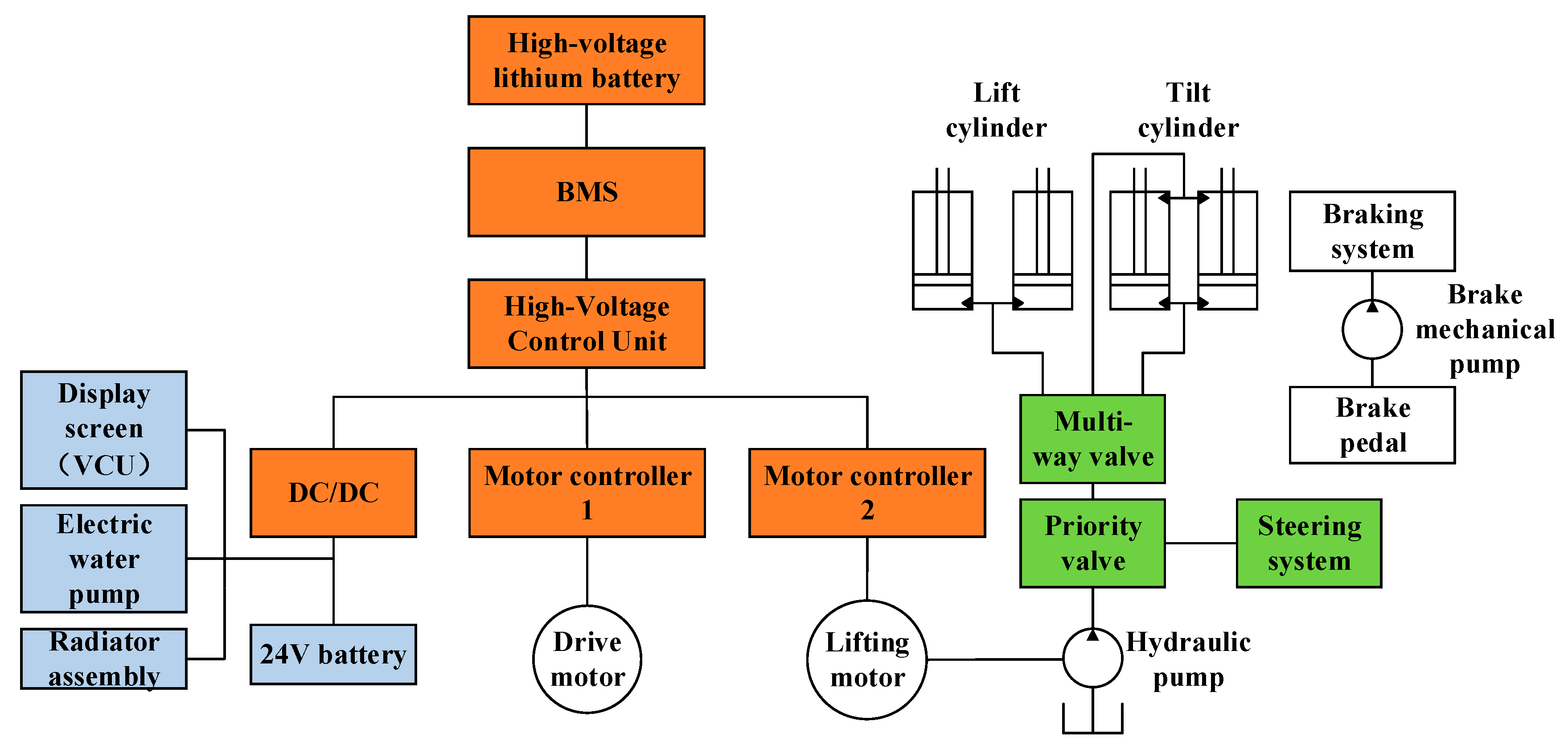
Figure 2 illustrates the basic composition of the designed high-voltage lithium battery electric forklift powertrain, with its energy storage unit supplied by high-voltage lithium batteries managed by the battery management system (BMS). The high-voltage lithium battery in this powertrain system needs to supply power to three circuits (the drive motor, the lifting motor, and the DC/DC converter). A process for powering on and off high-voltage lithium battery electric forklifts has been developed, suitable for this powertrain system. The High-Voltage Management Unit (HVMU) manages the pre-charging control, energy distribution, and high-voltage electrical protection functions for the entire forklift. The vehicle control strategy also incorporates a fault handling module to ensure the safety of the powertrain system during its operational process.

3.2. Forklift Operation Analysis

The forklift powertrain is designed by analyzing the operational characteristics of forklifts. Forklifts exhibit different operating modes and patterns under various working conditions. The most common application for 3-ton electric forklifts is in warehousing and logistics, where they are primarily used for loading, unloading, and short-distance transportation of goods. When deployed for cargo handling in warehouse operations, the forklift typically follows the cyclic route illustrated in Figure 3. The forklift follows a cyclic operation sequence, Position X—Route 1—Position A—Route 2—Position X—Route 3—Position B—Route 4—Position Y—Route 5—Position X, thereby facilitating the transportation of goods from Location A to Location B.
During the aforementioned cyclic operations, the electric forklift primarily involves six different working conditions: travel movement, mast lifting, mast lowering, mast tilting backward, mast tilting forward, and travel steering [26], as illustrated in Figure 4.

4. Test Research and Analysis

4.1. Prototype Hardware Configuration

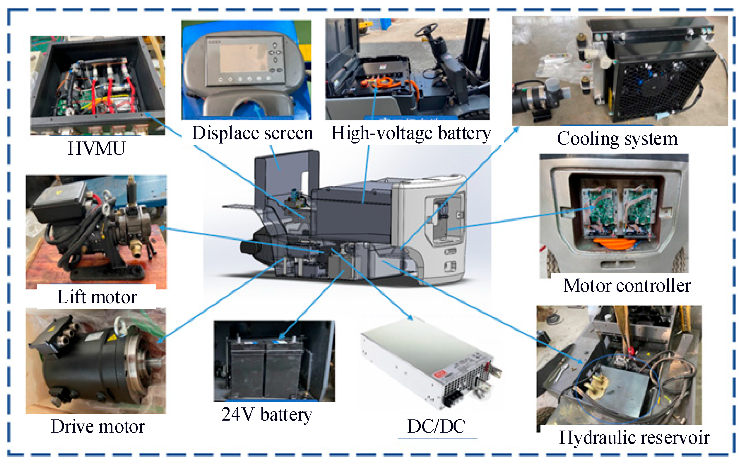
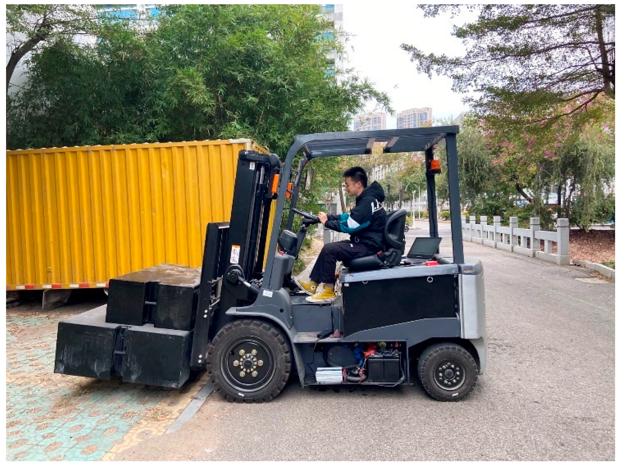
Based on the designed powertrain solution for high-voltage lithium battery electric forklifts, the original 3-ton electric forklift was retrofitted, as illustrated in Figure 5. A physical photograph of the experimental prototype is shown in Figure 6.
For the 3-ton high-pressure lithium battery electric forklift testing prototype constructed in this study, experiments were carried out on a flat, paved surface in the laboratory. The experimental procedures and methods strictly adhered to the industry standard “Test Methods for Counterbalanced Forklift Trucks” (JB/T 3300-2024), encompassing the operating route and sequence of cyclic operations. In compliance with the test specifications, the experiment lasted for over 1 h of continuous operation, during which 37 cycles were completed. Throughout the testing process, a qualified operator, who had received appropriate training, was responsible for controlling the forklift’s operation and load handling while adhering to the requirements specified in the standard “Industrial Trucks—Safety Rules for Application, Operation and Maintenance” (ISO 21262:2020).
The effectiveness of the proposed powertrain was validated through whole-vehicle energy consumption tests, and the system’s energy efficiency was evaluated. A photograph of the on-site energy consumption testing is shown in Figure 7.

4.2. Analysis of Average Energy Consumption Measurement Results

According to the parameters of the 3-ton high-voltage lithium battery forklift prototype, the specific test parameters for the average energy consumption experiment are shown in Table 2. Each lifting and traveling operation are performed at the maximum load capacity of 3000 kg, with the test load composed of standard weights (2000 kg + 1000 kg). The physical setup of the standard test weights is illustrated in Figure 8.
Data collection of vehicle parameters was conducted throughout the entire testing process. CAN messages containing the battery’s total voltage and total current were extracted and decoded, with corresponding voltage and current curves plotted. Based on the recorded data, the 3-ton high-voltage lithium battery forklift operated for a total test duration of 4026 s during the average energy consumption test, completing 37 duty cycles with an average cycle time of 108.81 s per cycle.
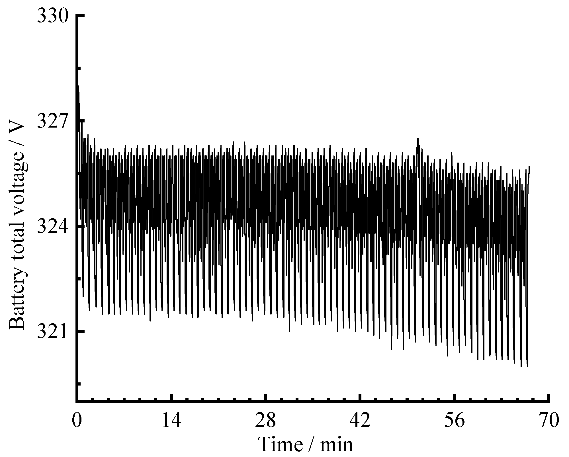
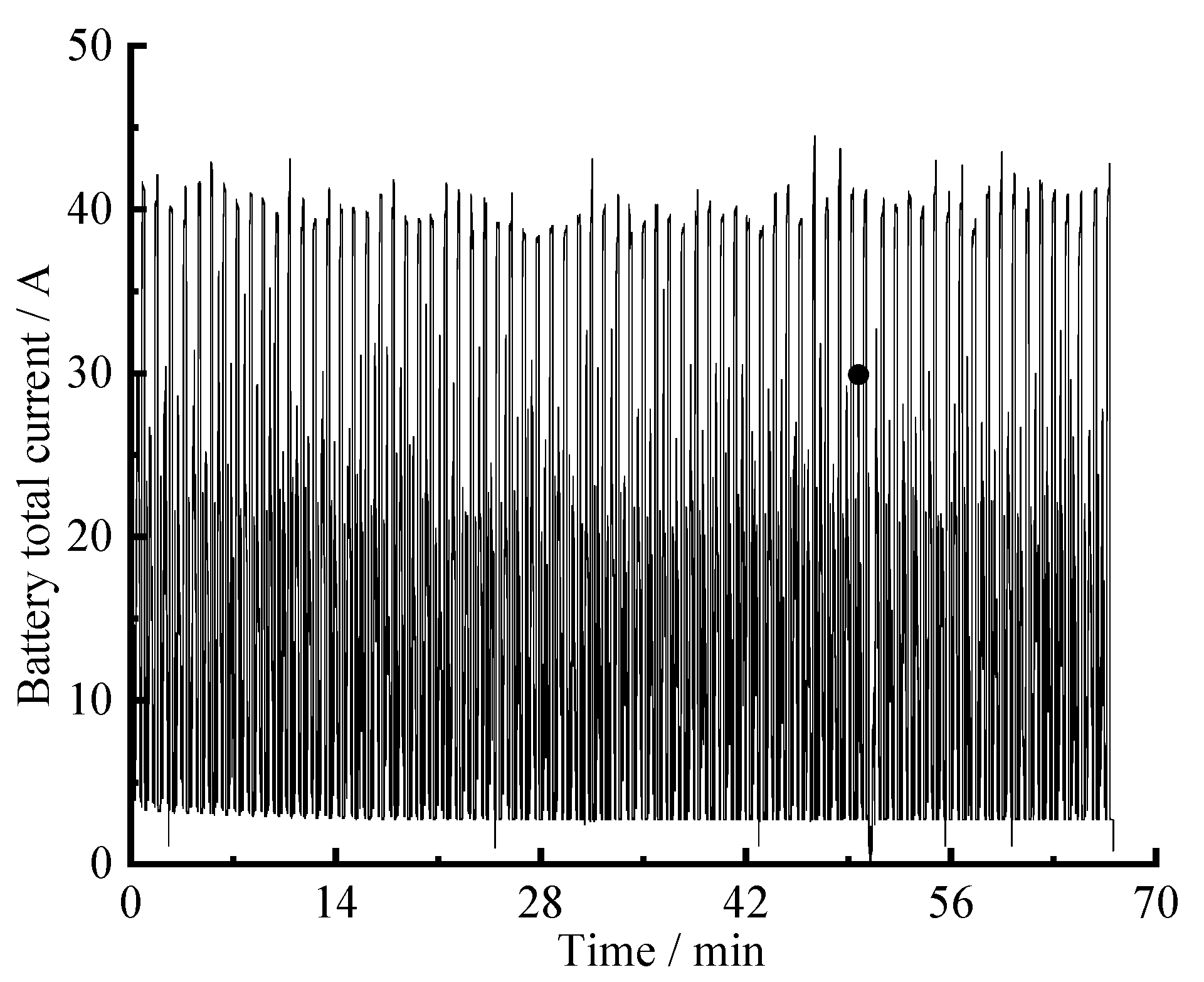
As shown in Figure 9, the battery voltage curve demonstrates minor fluctuations (320~328.5V range) corresponding to different operational states within each cycle. Figure 10 presents the battery current profile, which varies significantly with instantaneous power demand—peaking at 44.5 A during full-load lifting operations when the lift motor requires maximum power output.
By integrating the battery current shown Figure 10, the total consumed capacity during these 37 operational cycles was calculated as 19.07 Ah. Using Formula (3), the number of allowable cycles for this battery under such operating conditions can be determined.
n x = η b Q Q d
where nx is the number of allowable cycles for the battery; Qd is the average consumed capacity per cycle.
The operational duration of the battery under average energy consumption testing conditions is
t m = n x T d 3600
where tm is the battery’s available test cycle duration. Td is the average time per cycle.
The operational duration of the 3-ton high-voltage lithium battery forklift prototype under normal working conditions can be estimated based on the working time obtained from the average energy consumption test, as calculated by Formula (5).
t G = K t m
where tG is the battery operational time for the prototype. K is the forklift user work factor (2.0~3.0).
The total power output of the storage battery during experimental operation can be obtained through CAN messages transmitted by the BMS, as illustrated in Figure 11. Given the relatively stable battery voltage fluctuations, the periodic trend in the total power output curve closely resembles that in the total current curve, with a maximum power of 14.3 kW. By integrating the curve, the total energy consumption of the prototype during the average energy consumption test can be calculated.
W c 1 = 0 t P c 1 d t c 1 3600
where Wc1 is the total energy consumption of the prototype during the average energy consumption test. Pc1 is the battery total output power. tc1 is the test duration of the prototype during the average energy consumption trial.
Based on the aforementioned calculations, under standard energy consumption test conditions, the 3-ton high-voltage lithium-electric forklift prototype recorded a total test energy consumption of 6.16 kWh. The battery’s total capacity allows for 184 cycles of operation and can support 5.56 h of continuous work under these conditions. The hourly energy consumption of this prototype is 1.11 kWh, which is clearly lower than the approximately 4.05 kWh of traditional 3-ton low-pressure forklifts or lead-acid forklifts. By multiplying by the forklift user’s operational duty factor, it can be determined that the prototype can operate for 11.12 to 16.68 h under normal working conditions. However, to prevent complete battery depletion during user operation, a 20% capacity reserve must be maintained. This reserve ensures sufficient power for forklift relocation to charging stations and prevents over-discharge, which would otherwise degrade battery lifespan. With this 20% reserve, the prototype’s operational duration under normal conditions reduces to 8.89~13.34 h, meeting the 7.5 h single-shift requirement specified in the battery selection design criteria.
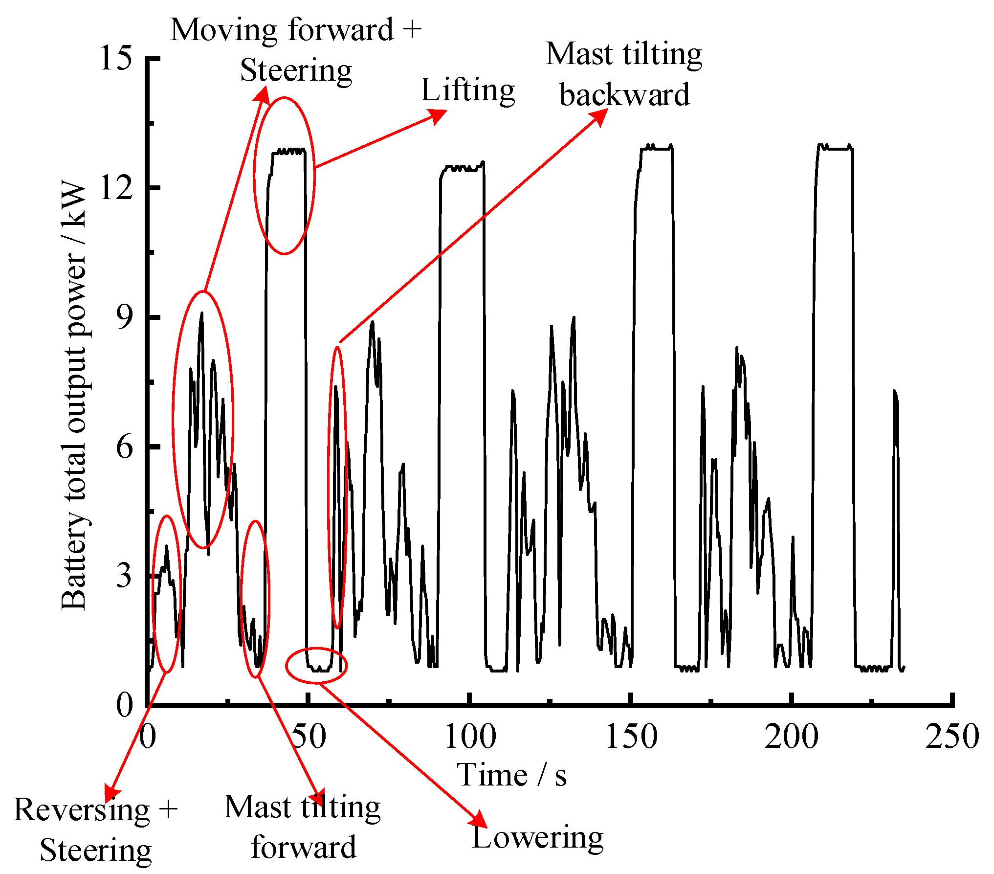
As shown in Figure 12, the battery total output power curves for two cycles of the 3-ton high-voltage lithium battery electric forklift prototype during average energy consumption testing are presented. Different operating conditions of the electric forklift can be distinguished through lift signals, tilt signals, throttle signals, and brake signals, as indicated in Figure 12. By conducting integral analysis at each stage, the energy consumption ratio under different conditions can be calculated, according to the following formula and results detailed in Table 3:
R i = m = 1 n E c y c l e , m , i E t o t a l   × 100 % = m = 1 n t s , m , i t e , m , i P ( t ) d t t s t e P ( t ) d t
where i is the i-th working condition in a single cycle, with a total of six working conditions. Ri is the energy consumption proportions under the working condition i. Etotal is the total energy consumption under all operating conditions during the entire test period. Ecycle,m,i is the energy of condition i during the m-th cycle. n is the total number of cycles, which is 37. ts,m,i is the start time of condition i during the m-th cycle. te,m,i is the end time of condition i during the m-th cycle. ts is the test start time. te is the test end time.
When the 3-ton high-voltage lithium battery electric forklift operates under rated load conditions, its peak energy consumption occurs during full-load lifting, accounting for over 50% of the total energy consumption in the average energy consumption test. The travel power system, which includes forward/reverse motion and steering, accounts for 36.7% of total energy consumption during the average test.
During the lowering of heavy loads, as the forklift remains stationary (parked), only the lifting cylinder performs the lowering action. The lifting motor enters energy-saving standby mode due to the absence of detected signals for lifting, tilting, throttle, or braking. In this state, the forklift’s primary energy consumption stems from powering auxiliary components and the operation of the DC/DC converter.
Through calculation and analysis of energy consumption proportions across different operating conditions during the average energy consumption test, it is revealed that: (1) Full-load lifting represents the highest energy consumption scenario, accounting for 53.1% of total energy use. (2) The travel power system ranks second, contributing 36.7% of total energy consumption.

4.3. Thermal Equilibrium Analysis During Normal Forklift Operations

To verify the energy efficiency of the proposed high-voltage lithium battery forklift powertrain, thermal equilibrium testing can be employed for validation and assessment. Prior to conducting thermal equilibrium testing, it is essential to calibrate the locations of temperature measurement points. In both the drive motor controller and lifting motor controller systems, the primary heat generation originates from power components, with IGBT (Insulated Gate Bipolar Transistor) modules being the most significant contributors due to their high heat output and temperature sensitivity. Therefore, temperature monitoring of the motor controllers focuses primarily on areas adjacent to the IGBT modules.
For the drive motor and lifting motor, temperature measurement points are established within their respective installation spaces. Both motors are positioned beneath the driver’s footrest cover and under the seat. Motor-generated heat directly impacts the operator’s working environment and may adversely affect adjacent electrical components, including the high-voltage management unit, battery enclosure, and DC/DC converter.
For the thermal equilibrium test of the 3-ton high-voltage lithium battery electric forklift, temperature data acquisition is performed in real time via the I/O interfaces of the two motor controllers. These controllers transmit the collected temperature information to the CAN bus through their integrated CAN communication modules. The host computer utilizes PCAN-Explorer5 software to record and perform real-time parsing of temperature messages on the bus.
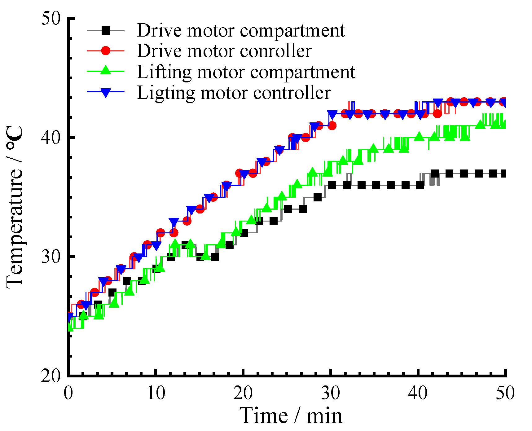
To expedite the prototype’s attainment of thermal equilibrium, this test adopts the same operational conditions as the average energy consumption test, employing a 3000 kg load with a duty cycle encompassing normal operations: traveling, steering, lifting, lowering, and tilting. This approach ensures rapid temperature elevation in both motors and their controllers. The temperature acquisition results from the prototype’s thermal equilibrium test are presented in Figure 13.
As indicated by the curves in Figure 13, the ambient temperature at the thermal equilibrium test site was 24 °C. Comparative analysis reveals that both the drive motor controller and lifting motor controller exhibited faster temperature increases, reaching higher temperatures than their respective motor compartments. After approximately 30 min of continuous operation, the temperatures of the drive motor controller, lifting motor controller, and drive motor compartment began to stabilize at 42 °C, 42 °C, and 36 °C, respectively, while the lifting motor compartment temperature continued to rise gradually. The continued temperature rise in the lifting motor compartment can be attributed to the following factors:
(1)
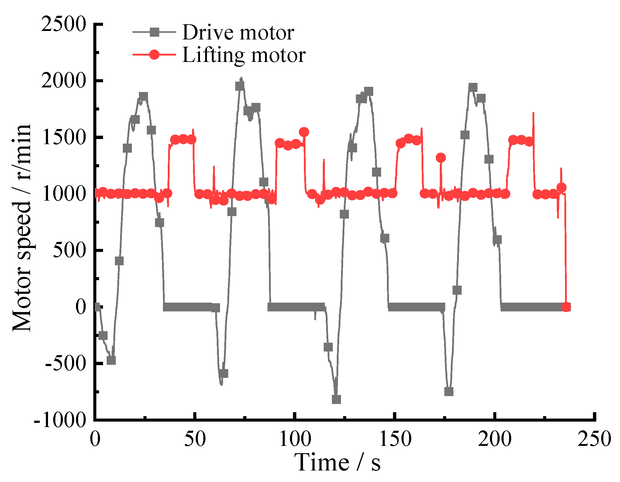
Motor Operating Modes: As shown in Figure 14, which displays motor speed curves over two test cycles, the lifting motor operated nearly continuously at full-load lifting and 1000 r/min idle speed throughout the test. In contrast, the drive motor followed an intermittent operation pattern, resulting in sustained heat generation in the lifting motor.
(2)
Cooling System Configuration: the drive motor employs a dedicated cooling water circuit, whereas the lifting motor’s cooling system is connected in series to the rear ends of both motor controllers. This configuration causes residual heat from the upstream water circuit to further elevate temperatures in the lifting motor compartment.
(3)
Thermal Environment Differences: The drive motor is mounted at the rear of the forklift’s front drive axle, allowing natural heat dissipation during vehicle movement. Conversely, the lifting motor is installed beneath the battery pack and adjacent to the hydraulic oil tank, creating a relatively enclosed space that retains heat while also being affected by thermal radiation from the hydraulic system.
Ultimately, the lifting motor reached thermal equilibrium at 43 min, with the entire vehicle operating under steady-state thermal conditions.
In summary, under the average energy consumption test conditions, the 3-ton high-voltage lithium battery electric forklift prototype required 43 min to reach thermal equilibrium across the entire vehicle. At this point, the thermal equilibrium temperatures were recorded as follows: 43 °C for both the drive motor controller and lifting motor controller, 37 °C for the drive motor compartment, and a sustained fluctuation between 41 and 42 °C for the lifting motor. Given that the motor controllers’ shutdown protection temperature is set at 80 °C, and all components remained far below this threshold after achieving thermal equilibrium, the vehicle’s cooling system is verified to ensure long-term stable operation of the 3-ton high-voltage lithium battery electric forklift.

5. Conclusions

To further enhance the energy efficiency of electric forklifts, this paper proposes a high-voltage lithium battery electric forklift powertrain solution and conducts comprehensive energy consumption and thermal equilibrium analyses. The following conclusions are derived:
(1)
The construction of the 3-ton high-voltage lithium battery electric forklift test prototype was completed. Based on standardized testing protocols, average energy consumption measurements confirm that the proposed high-voltage system enables 8.89 to 13.34 h of continuous operation, significantly exceeding the 7.5 h service duration achieved by low-voltage lithium battery counterparts.
(2)
Based on average energy consumption experiments, the full-load lifting operation represents the highest energy consumption mode for the complete vehicle, accounting for 53.1% of total energy use, followed by the driving power system at 36.7%.
(3)
All electronic control units (ECUs) in the vehicle maintain thermal equilibrium temperatures below 43 °C, under the 80 °C shutdown threshold for low-voltage forklifts. This ensures long-term stable operation of the equipment while further demonstrating the lower energy consumption characteristics of the high-voltage lithium battery system.
Future development will fully account for the frequent start-stop operations inherent in forklift working cycles [27], which generate substantial regenerative braking energy. By integrating walking energy recovery control strategies into the system architecture, we aim to further enhance the energy efficiency of high-voltage lithium battery forklifts. However, this study also has limitations: (1) Testing was only performed on a single prototype, failing to reflect the “cumulative effects of long-term multi-shift operations”. (2) Further specific research is needed to confirm the advantages of the high-voltage lithium-ion powertrain in larger-tonnage forklifts.

Author Contributions

X.W. and T.L. conceived and designed the experiments; X.W. and C.M. performed the experiments; J.C. and W.G. analyzed the data; X.W. and Z.L. wrote the paper. All authors have read and agreed to the published version of the manuscript.

Funding

This research was funded by National Natural Science Foundation of China—Regional Innovation and Development Joint Fund (Grant No. U24A20110), National Natural Science Foundation of China (Grant No.52175051), Natural Science Foundation of Fujian province (Grant No 2023J01118), Quanzhou City “Unveiling the List and Assigning the Leadership” Project (Grant No.2024QZGZ6), and Shanghai Municipal Administration for Market Regulation (Grant No.2024BZ13).

Institutional Review Board Statement

Not applicable.

Informed Consent Statement

Not applicable.

Data Availability Statement

Data is contained within the article.

Conflicts of Interest

The authors declare no conflicts of interest.

References

  1. Copetti, D.F.; Canha, L.N.; Botezeli, L.K.; Tolotti, D.; Schmidt, E.; Silva, J.V.D.C.; NeuhausSchneider, A.J.; Da Silva, G.K.; Eggers, D. Electric Forklifts: Technological Advancements and Impacts on Energy Transition and Sustainability. In Proceedings of the 2023 15th Seminar on Power Electronics and Control (SEPOC), Santa Maria, Brazil, 22–25 October 2023; IEEE: New York, NY, USA, 2023; Volume 10, pp. 1–6. [Google Scholar]
  2. Jiao, M.; Pan, F.; Huang, X.; Yuan, X. Evaluation on Total Cost of Ownership of Electric Forklifts with lithium-ion battery. In Proceedings of the 2021 4th International Electrical and Energy Conference (CIEEC), Wuhan, China, 28–30 May 2021; IEEE: New York, NY, USA, 2021; pp. 1–5. [Google Scholar]
  3. Yudhistira, R.; Khatiwada, D.; Sanchez, F. A comparative life cycle assessment of lithium-ion and lead-acid batteries for grid energy storage. J. Clean. Prod. 2022, 358, 131999. [Google Scholar] [CrossRef]
  4. Sadeq, A.M. Hybrid and Electric Vehicles: A Comprehensive Guide, 1st ed.; Routledge: London, UK, 2024; pp. 104–112. [Google Scholar]
  5. Lin, T.; Lin, Y.; Ren, H.; Chen, H.; Li, Z.; Chen, Q. A double variable control load sensing system for electric hydraulic excavator. Energy 2021, 223, 119999. [Google Scholar] [CrossRef]
  6. Saeed, B.; Yilma, C.; Kivanc, O.; Tuncay, R.N. Development of a Hybrid Energy Storage System for a Forklift Vehicle. In Proceedings of the 2024 6th Global Power, Energy and Communication Conference (GPECOM), Budapest, Hungary, 4–7 June 2024; IEEE: New York, NY, USA, 2024; Volume 6, pp. 120–125. [Google Scholar]
  7. Cheng, L.; Zhao, D.; Li, T.; Wang, Y. Modeling and simulation analysis of electric forklift energy prediction management. Energy Rep. 2022, 8, 353–365. [Google Scholar] [CrossRef]
  8. Zhang, K.; Chen, J. Research on Potential Energy Recovery System Control Strategy for Electric Forklifts. China Mech. Eng. 2015, 26, 844–851. [Google Scholar]
  9. Yu, C.; Wang, Y.; Zhao, C. Forklift hydraulic system design. Appl. Mech. Mater. 2013, 303–306, 2748–2753. [Google Scholar] [CrossRef]
  10. Yang, W.; Ke, J.; Yang, Z.; Wang, Y.; Li, L. Design and Simulation of Hydrostatic Transmission System in Electric Forklift. Mach. Tool Hydraul. 2020, 48, 71–75. [Google Scholar]
  11. Wang, W. Research on Key Technologies of the Drive System for 3T Electric Forklift. Master’s Thesis, Chang’an University, Xi’an, China, 2021. [Google Scholar]
  12. Li, J.; Lutzemberger, G.; Poli, D.; Scarpelli, C.; Piazza, T. Simulation and experimental validation of a hybrid forklift truck. In Proceedings of the 2019 AEIT International Conference of Electrical and Electronic Technologies for Automotive (AEIT AUTOMOTIVE), Turin, Italy, 2–4 July 2019; IEEE: New York, NY, USA, 2019. [Google Scholar]
  13. Sayed, K.; Kassem, A.; Saleeb, H.; Alghamdi, A.S.; Abo-Khalil, A.G. Energy-saving of battery electric vehicle powertrain and efficiency improvement during different standard driving cycles. Sustainability 2020, 12, 10466. [Google Scholar] [CrossRef]
  14. Mazali, I.I.; Daud, Z.H.C.; Hamid, M.K.A.; Tan, V.; Samin, P.M.; Jubair, A.; Ibrahim, K.A.; Kob, M.S.C.; Xinrui, W.; Talib, M.H.A. Review of the methods to optimize power flow in electric vehicle powertrains for efficiency and driving performance. Appl. Sci. 2022, 12, 1735. [Google Scholar] [CrossRef]
  15. Tong, Z.; Guan, S.; Zhang, Q.; Cao, X.E. Data-driven energy efficient speed planning for battery electric industrial vehicles: Forklift as a case study. J. Clean. Prod. 2024, 443, 140923. [Google Scholar] [CrossRef]
  16. Tong, Z.; Jiang, Y.; Tong, S.; Zhang, Q.; Wu, J. Hybrid drivetrain with dual energy regeneration and collaborative control of driving and lifting for construction machinery. Autom. Constr. 2023, 150, 104806. [Google Scholar] [CrossRef]
  17. VDI 2198; Type Sheets for Industrial Trucks. Verein Deutscher Ingenieure (VDI): Düsseldorf, Germany, 2018.
  18. PN-EN IS0 50001; Energy Management System -Requirements and Recommendations for Use. Polish Committee for Standardization (PKN): Warsaw, Poland, 2012.
  19. Zajac, P.; Rozic, T. Energy consumption of forklift versus standards, effects of their use and expectations. Energy 2022, 239, 122187. [Google Scholar] [CrossRef]
  20. Tong, Z.; Guan, S. Developing high-precision battery electric forklift driving cycle with variable cargo weight. Transp. Res. Part D. Transp. Environ. 2024, 136, 104443. [Google Scholar] [CrossRef]
  21. JB/T 3300-2024; Counterbalance Lift Trucks—Testing Method for Whole Machines. China Machine Press: Beijing, China, 2024.
  22. ISO 21262:2020; Industrial Trucks—Safety Rules for Application, Operation and Maintenance. The International Organization for Standardization (ISO): Geneva, Switzerland, 2020.
  23. IEC 62619:2022; Secondary Cells and Batteries Containing Alkaline or Other Non-Acid Electrolytes—Safety Requirements for Secondary Lithium Cells and Batteries, for Use in Industrial Applications. The International Electrotechnical Commission (IEC): Geneva, Switzerland, 2022.
  24. Shahid, S.; Agelin-Chaab, M. A review of thermal runaway prevention and mitigation strategies for lithium-ion batteries. Energy Convers. Manag. X 2022, 16, 100310. [Google Scholar] [CrossRef]
  25. Global EV Outlook 2024, IEA. Available online: https://www.iea.org/reports/global-ev-outlook-2024 (accessed on 24 August 2025).
  26. Fu, S.; Chen, H.; Ren, H.; Lin, T.; Miao, C.; Chen, Q. Potential Energy Recovery System for Electric Heavy Forklift Based on Double Hydraulic Motor-Generators. Appl. Sci. 2020, 10, 10113996. [Google Scholar] [CrossRef]
  27. Jiang, Y.; Tong, Z.; Tong, S.; Xu, Z.; Li, Y. Hydraulic dual-module hybrid driving system with adjustable waste energy recovery for industrial vehicles. Energy 2024, 307, 132546. [Google Scholar] [CrossRef]
Figure 1. Schematic of traveling drive system of single-drive motor system.
Applsci 15 09854 g001
Figure 2. Basic components of the powertrain for high-voltage lithium battery electric forklifts.
Applsci 15 09854 g002
Figure 3. Forklift Handling Route Map. The forklift starts at Position X and performs a cyclic operation of transporting goods from Location A to Location B. The operation follows a repetitive sequence: Position X → Route 1 → Location A → Route 2 → Position X → Route 3 → Location B → Route 4 → Position Y → Route 5 → Position X.
Applsci 15 09854 g003
Figure 4. Forklift duty cycle diagram.
Applsci 15 09854 g004
Figure 5. System architecture of the 3-ton high-voltage lithium battery electric forklift prototype.
Applsci 15 09854 g005
Figure 6. Physical image of the 3-ton high-voltage lithium battery electric forklift test prototype.
Applsci 15 09854 g006
Figure 7. On-site testing photos of the 3-ton high-voltage lithium battery electric forklift.
Applsci 15 09854 g007
Figure 8. Physical image of the load standard weights.
Applsci 15 09854 g008
Figure 9. Battery total voltage.
Applsci 15 09854 g009
Figure 10. Battery total current.
Applsci 15 09854 g010
Figure 11. Battery total output power.
Applsci 15 09854 g011
Figure 12. Battery output power curve.
Applsci 15 09854 g012
Figure 13. Thermal equilibrium during normal operation.
Applsci 15 09854 g013
Figure 14. Motor speed during the thermal equilibrium test.
Applsci 15 09854 g014
Table 1. Battery parameters.
Parameter NameValues
Battery typeLiFePO4 battery (Lithium Iron Phosphate battery, Anhui Qianhang New Energy Technology Co., Ltd., Bengbu, China)
Number of cells in series/parallel1P100S
Nominal voltage320 V
Nominal capacity100 Ah
Total battery capacity32 kWh
Operating voltage range250~365 V
Maximum continuous discharge current100 A
Peak discharge current (10 s)200 A
Communication methodCAN (Controller Area Network) communication
Table 2. Parameters during the average energy consumption test.
ItemsValue
Rated load m03000 kg
Moving distance L030 m
Maximum lifting height2000 mm
Test time tc14026 s
Cycle number37 times
Environmental Temperature(25 ± s2 °C)
Table 3. Energy consumption proportions under different operating conditions.
ItemsConditionsEnergy Consumption Proportions
1Reversing + Steering7.1%
2Moving forward + Steering29.6%
3Mast tilting forward3.7%
4Lifting53.1%
5Lowering2.1%
6Mast tilting backward4.4%
Disclaimer/Publisher’s Note: The statements, opinions and data contained in all publications are solely those of the individual author(s) and contributor(s) and not of MDPI and/or the editor(s). MDPI and/or the editor(s) disclaim responsibility for any injury to people or property resulting from any ideas, methods, instructions or products referred to in the content.