Article

Toppling Deformed Rock Mass Hydraulic Fracturing Analysis Based on Extended Finite Elements

Earth Sciences and Engineering College, Hohai University, Nanjing 210098, China
*
Author to whom correspondence should be addressed.
Appl. Sci. 2025, 15(18), 10177; https://doi.org/10.3390/app151810177
Submission received: 25 July 2025 / Revised: 31 August 2025 / Accepted: 15 September 2025 / Published: 18 September 2025

Abstract

Natural cracks are prone to form in toppling deformed rock masses during the toppling process, and these cracks are likely to undergo hydraulic fracturing failure under the action of high water head. This paper leverages the advantage of the extended finite element method (XFEM) in simulating crack propagation, considers the effect of water pressure on the crack surface, conducts numerical simulation and analysis on the hydraulic fracturing of cracks in toppling deformed rock masses, and studies the influences of different crack lengths, rock formation dip angles and crack surface water pressures on crack propagation. The main conclusions are as follows: (1) After hydraulic fracturing occurs in the rock mass, with the continuous rise in the water level, the crack propagation rate is slow first and then fast. When the water pressure is low, microcracks extend slowly; when the water pressure reaches a certain level, the rock formation cracks expand rapidly and eventually fracture. (2) Under the same water pressure, rock formations with longer initial crack lengths are more prone to hydraulic fracturing, and their cracks expand faster; rock formations with a dip angle of 45° are more likely to undergo hydraulic fracturing than those with other dip angles, while rock formations with a dip angle close to 90° are hardly susceptible to hydraulic fracturing. (3) The instability failure mechanism of hydraulic fracturing in toppling deformed rock masses is tension shear action. As the fissure water pressure rises, the tensile stress at the crack tip will increase sharply. Once new microcracks appear in the initial crack, it will be in an unstable expansion state.

1. Introduction

Rockslides are a serious natural disaster that can easily cause casualties and huge economic losses [1]. Among them, toppling deformation and failure is a typical form of deformation and failure of layered rock masses. With the increasing global energy demands and rapid infrastructure development, the investigation of crack propagation and failure mechanisms in rock engineering has emerged as a pivotal research focus in geomechanics, hydraulic engineering, and energy development [2,3,4]. In recent years, during the construction of hydropower projects in southwest China, toppling deformed rock masses are often distributed at certain elevations on bank slopes, whether in dam site areas or reservoir areas. The toppling deformation and failure of rock masses are usually influenced by engineering geological and rock mass mechanical environmental factors such as the physical properties of the rock mass, tectonic stress, and other external forces. The forms and degrees of their development often show strong spatial and temporal differences. In toppling deformed rock slopes where the water level of some rivers or reservoirs often fluctuates, water pressure is usually an important factor causing the failure of toppling deformed rock masses. Hydraulic fracturing is a physical phenomenon in which microcracks in rock masses initiate, propagate, and eventually develop into macroscopic cracks under the action of high water pressure, leading to instability and failure [5,6,7]. During the bending and fracturing of toppling rock masses, tensile fractures of varying degrees form on their surfaces. Consequently, rock masses are highly susceptible to hydraulic fracturing under high water pressure. In practical engineering scenarios such as hydraulic fracturing, tunnel excavation, and the construction of underground energy storage caverns, the processes of crack initiation, propagation, and penetration in rock under coupled stress seepage fields directly influence the safety and operational reliability of engineering structures [8]. Therefore, studying the influence of hydraulic fracturing force on rock masses is of great significance for theoretical and practical guidance.
The fundamental cause of hydraulic fracturing in rock masses is that the stress intensity factor at the crack tip exceeds the fracture toughness of the rock mass [9]. Azarov, A et al. [10] showed that the path of the hydraulic fracture depends strongly on the hydrostatic stress in the medium and the distance between the crack and the cavity. Liu, Y et al. [11] suggested that a lower rock tensile strength and natural fractures’ cementation strength improved the main fracture length. A higher tensile strength of rock increased the initiation pressure of the induced fracture, while the cementing strength of the natural fractures showed no impact on it. Tang, X et al. [12] indicated that the GMTS criterion, considering T stress, is more suitable for describing the characteristics of Type I–II composite fractures under rock-splitting loads. Liu, T et al. [13] showed that crack initiation strength is inversely related to hydraulic pressure, that hydraulic pressure aggravates the wing crack’s growth, and that the wing crack’s behavior under high hydraulic pressure shifts from stable to unstable expansion. Huang Y et al. [14] studied the condition of high-pressure water, derived the expression between the permeability coefficient of fractured rock masses and water pressure, and provided the calculation formulas for the permeability coefficient before and after hydraulic fracturing. Li et al. [15] derived the analytical formula for the fracture strength of rock masses considering the additional water pressure in fractures using the compression shear fracture criterion. Zhang, J et al. [16] obtained the phase field governing equation considering plastic damage coupling, enabling the simulation of the energy evolution in rock from the elastic stage to plastic damage and unstable failure. Research on hydraulic fracturing mainly adopts four types of methods: in situ tests, model tests, numerical simulations, and analytical analyses. Hu et al. [17] used a scaled-down model test to analyze the hydraulic fracturing deformation characteristics of dams under different water pressures and initial crack lengths. Liu et al. [18] carried out a series of physical simulation tests on hydraulic fracturing under true triaxial stress conditions. They used acoustic emission devices to monitor the propagation of hydraulic fractures in real time and analyzed the key influencing factors of the interaction between holes and hydraulic fractures as well as the characteristics of typical fracturing curves. Huang, W. et al. [19] conducted triaxial tests under different hydraulic pressures and low surrounding pressures to study the effect of hydraulic pressure on the mechanical properties of laminated rocks. With the rapid development of computer technology, numerical analysis methods have also been increasingly widely applied to the research on rock mass hydraulic fracturing. Liu, W. et al. [20] adopted FLAC3D finite element software to construct a cylindrical hard rock model with intermediate prefabricated holes to simulate the effect of water pressure on rock mechanics. Zhang et al. [21] implemented a brittle material phase field fracture model in the COMSOL 5.5 Multiphysics platform, clarifying through sensitivity analysis the influences of Young’s modulus and the critical energy release rate on crack trajectories. Liu et al. [22] simulated hydraulic fracturing in bedded shale using PFM yet treated the rock as purely elastic. At present, the numerical simulation of hydraulic fracturing is relatively complex. The numerical calculation methods applicable to hydraulic fracturing analysis include the finite difference method, finite element method, boundary element method, among others. Among these, the finite element method remains the most widely used and mature numerical method. The extended finite element method (XFEM) is more effective than other numerical analysis methods. The basic principle of the XFEM is to incorporate enrichment functions into the framework of the conventional finite element method based on the idea of partition of unity to reflect discontinuities. Zhao H J et al. [23] established a continuous discontinuous coupled hydro-mechanical model and studied the propagation laws of hydraulic fracturing under different conditions. Cao Z et al. [24] established a statistical damage constitutive model and a finite element numerical algorithm for rock masses and verified their effectiveness through triaxial compression tests. Sheng M et al. [25] applied XFEM to simulate the hydraulic fracturing process in rock masses, presented the propagation paths of hydraulic cracks, and compared them with experimental results, thus verifying the reliability of XFEM in simulating hydraulic fracturing in rock masses. Yongping Y et al. [26] based on the extended finite element method, established a new model for hydraulic fracturing in horizontal wells containing gas, water, and sand using the cohesive zone method, and obtained the fracture development patterns and propagation laws of a silty hydrate reservoir. Zheng et al. [27,28] introduced additional functions reflecting the local characteristics of fractures at the additional nodes of fracture-containing elements, derived the hydraulic fracturing control equations based on XFEM, and carried out simulations of the tunnel cracking process under the action of fracture water pressure as well as the hydraulic fracturing process of the main controlling structural planes of dangerous rocks. Shi et al. [29] analyzed the influences of different crack lengths, angles, and water pressures on crack surfaces on crack propagation in concrete gravity dams based on the extended finite element method. Hu [30] conducted a numerical simulation and analysis of the hydraulic fracturing in hydraulic pressure tunnels using the extended finite element method (XFEM), and the results showed that hydraulic fracturing has a minor impact on the Mode II stress intensity factor, while it leads to an increase in the Mode I stress intensity factor.
The occurrence of bending and fracturing of a toppling deformed rock mass requires not only the fulfillment of mechanical conditions, but also the fulfillment of certain hydraulic conditions for a soft fracture surface. The formation of weak rupture surface is closely related to the development process of slope cracks: when groundwater infiltrates into the cracks, the water pressure inside the cracks rises, the cracks continue to expand, leading to the permeability of the slope of the toppling deformed rock mass being enhanced, and the rate of water infiltration is accelerated until the cracks penetrate through the slope destabilization and cause immediate destruction. Previously, there are relatively few studies on hydraulic fracturing of toppling deformed rock masses; therefore, in order to simulate the fracturing effect of the magnitude of the water pressure on a toppling deformed rock mass, this paper utilizes the finite element software ABAQUS for simulation, arranges the cracks by prefabrication, applies the theory of the maximum circumferential tensile stress intensity factor, and analyzes the crack propagation of the toppling rock mass with the help of the subroutine XFEM in the software. The research includes (1) the establishment of a numerical model of a toppling deformed rock mass, setting different dip angles and initial crack lengths of the rock mass; (2) numerical simulation of crack propagation in a toppling deformed rock mass under high water pressure; and (3) the analysis of the relationship between the crack propagation state (crack extension length and tension width) and the dip angle and initial crack length and water pressure of the rock mass. Therefore, this study provides certain reference value for the engineering of toppling deformed rock slopes under high water pressure and has certain theoretical and practical significance.

2. Basic Theory

2.1. Extended Finite Element Method Displacement Equation

Based on the unit decomposition method, an additional function reflecting the local characteristics of the crack is introduced into the finite element approximate displacement expression, yielding the extended finite element approximate displacement calculation formula [31]:
u = i Ω N i x [ u i + H ( x ) a i i Ω Γ + i = 1 4 F l x b i ( l ) i Ω Λ ]
In this formula, Ω denotes the set of all discrete nodes; N i is the conventional finite element shape function; Ω Λ is the node set of the crack tip element (as shown by the square in Figure 1); Ω Γ is the node set of the crack propagation element (as shown by the triangle in Figure 1); u i is the conventional node degrees of freedom; a i is the additional degrees of freedom associated with the step function; and b i ( l ) is the crack tip additional degrees of freedom.
The step function for cracks penetrating the unit is defined as follows:
H ( x ) = + 1   Above   the   crack 1   Below   the   crack
Since the crack surface does not penetrate the crack tip element, the step function cannot reflect the deformation characteristics of the crack tip element. Therefore, it is necessary to introduce an additional function for the crack tip. The crack tip additional function F l x for an isotropic elastic body is expressed as follows:
F l x = r sin θ 2 cos θ 2 sin θ cos θ 2 sin θ sin θ 2
In the formula, r and θ are the local polar radius and angle of the crack tip, respectively.
For units containing additional functions, the relative displacement at a given point on the crack surface can be obtained from Formula (1).
w = u + u = 2 i Ω Γ N i a i + 2 r i Ω Λ N i b i ( l )
In the formula, w represents the relative displacement between crack surfaces.

2.2. Control Equation

After constructing the displacement model, the virtual work equation for the hydraulic fracturing problem in cracked structures can be derived using the virtual work principle.
Ω σ : δ ϵ d Ω = Ω b δ u d Ω + Γ t t δ u d S + Γ c p δ w d S
In the formula, δ u is the virtual displacement; and p, t, and b are the water pressure, external force, and body force on the crack surface, respectively.
The extended finite element discrete equation is
K d = f
d = u i , a i , b i ( 1 ) , b i ( 2 ) , b i ( 3 ) , b i ( 4 ) T
In the formula, K and f are the overall stiffness matrix and external force column vector, respectively; and d is the node displacement column vector, which includes the displacements of nodes in enriched units and conventional units.
The overall stiffness matrix is assembled from unit stiffness matrices, where the unit stiffness matrix K e is defined as
K e = Ω e ( B r ) T D B s d Ω   r ,   s = u ,   a ,   b
In the equation, Ω e is the sub-unit, and the crack surface lies on the boundaries of these units; B u , B a , and B b represent the equivalent nodal load vector.

2.3. Crack Propagation Criteria

Selecting the maximum circumferential stress theory [32] as the fracture criterion for crack propagation, the crack propagation angle θ c should satisfy
θ c = 2 a r c t a n 1 4 K I K II ± K I K II 2 + 8
In the formula, K I and K II are the stress intensity factors for Type I and Type II cracks, respectively.
The equivalent stress intensity factor K I e q formula is
K I e q = 1 2 K I 1 + cos θ c 3 K II sin θ c cos θ c 2

2.4. Stress Intensity Factor

The relationship between the interaction integral and the corresponding stress intensity factor is as follows [33]:
I 1,2 = 2 K I 1 K I 2 + K II 1 K II 2 / E
E = E Plane   stress E / 1 ν 2 Plane   strain
In the formula, K I 1 , K I 2 , K II 1 , and K II 2 are the stress intensity factors of Types I and II corresponding to states 1 and 2, respectively; and E is related to Young’s modulus E and Poisson’s ratio ν .
Set state 1 as the actual state and obtain the expanded finite element numerical solution; set state 2 as the auxiliary state and obtain the asymptotic field at the crack tip [34]. Use state 2 to be the Type I asymptotic field and set K I 2 = 1 , K II 2 = 0 to obtain the stress intensity factor for Type I in state 1.
K I ( 1 ) = I 1 ,   m o d e   I   E / 2
Use state 2 to be the Type II asymptotic field and set K I 2 = 0 , K II 2 = 1 to obtain the stress intensity factor for Type II in state 1.
K II ( 1 ) = I 1 ,   m o d e II   E / 2
Establish a local polar coordinate system with the crack tip as the origin and the tangent direction of the crack surface as the x 1 -axis. The interaction integral can be expressed in the form of an area integral.
I 1,2 = A σ i j 1 u i 2 x 1 + σ i j 2 u i 1 x 1 W 1,2 δ 1 j Q x j d A Γ c p j 1 u i 2 x 1 + p j 2 u i 1 x 1 Q d Γ
W 1,2 = σ i j 1 ε i j 2 + σ i j 2 ε i j 1 / 2
In the formula, I 1,2 is the interaction integral between states 1 and 2; σ i j , ε i j , and u i denote the stress, strain, and displacement components, respectively; δ 1 j is the Korolev symbol; A is the integration region around the crack tip; Q is the weighting function; W 1,2 is the interaction strain energy between states 1 and 2; and p j is the water pressure on the crack surface.

3. Computational Model and Parameters

Based on the failure characteristics of toppling deformed rock masses, natural cracks are prone to develop in rock masses during the downward toppling process. To simulate the splitting effect of water outlet pressure on cracks, a generalized model at the bending fracture surface of a toppling rock mass is established to analyze crack propagation. The finite element software ABAQUS is used for simulation. Cracks are arranged in a prefabricated manner, and the maximum circumferential tensile stress intensity factor theory is applied. The crack propagation analysis of the toppling rock mass is carried out with the help of the subroutine XFEM in the software.
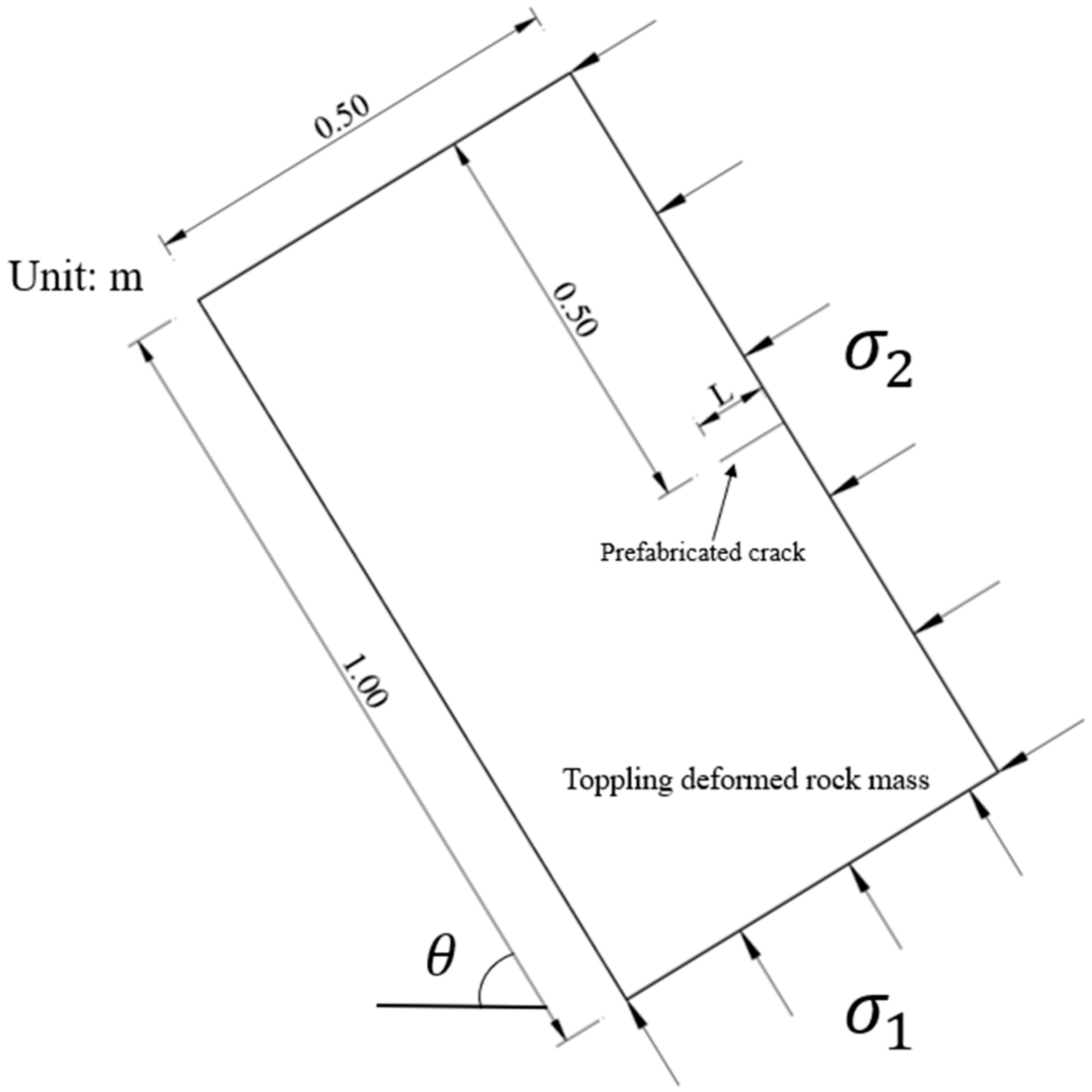
For the overturning of toppling rock masses, regardless of the failure mode, the failure of anti-dip slopes always initiates near the slope toe. Once the rock mass at the slope toe fractures or collapses, the upper rock mass can hardly maintain stability. Therefore, in this simulation, a section of rock formation at the toe of the toppling slope is selected for analysis. Set the rock mass model width to 0.50 m, model length to 1.00 m, initial crack length to a, and rock formation dip angle to θ . Apply horizontal constraints to the left and right boundaries of the model and vertical constraints to the bottom boundary. The rock mass material is defined to be isotropic. Assuming the rock mass is located 200 m below the summit, with an angle of 60° between the rock mass and the horizontal plane, a unit weight of 2.5 × 10⁴ kN/m3, and a lateral pressure coefficient of 0.5, calculations yield σ 1 = 5.6 MPa and σ 2 = 4.7 MPa. Therefore, the initial in situ stress is set to be σ 1 = 5.6 MPa and σ 2 = 4.7 MPa. To simulate the fracturing effect of water pressure on cracks, water was applied via injection. The injection point was located at the midpoint of the initial crack, where concentrated pore seepage flow was introduced. Water pressure was adjusted by controlling the injection rate. At an injection rate of 0.001 m3/s and an injection duration of 1 s, the water pressure reached 1.0 MPa, corresponding to a total head of 100 m. Assuming the water volume within the fracture is not compressible, the flow is Newtonian fluid, satisfying friction laws, the fracture walls are low-permeability rock with negligible filtration loss, and the fracture undergoes expansion under the internal pressure of the water flow. Model parameters are shown in Table 1; the geometric model is shown in Figure 2. Set the X-direction perpendicular to the initial crack, representing the crack opening width; set the Y-direction parallel to the initial crack, representing the crack propagation length.

4. Results

4.1. Different Initial Crack Lengths

Set the initial crack length of the rock formation (L) to 20 mm, 50 mm, 75 mm, and 100 mm, with a rock formation dip angle of 60°.
(1) Crack opening width
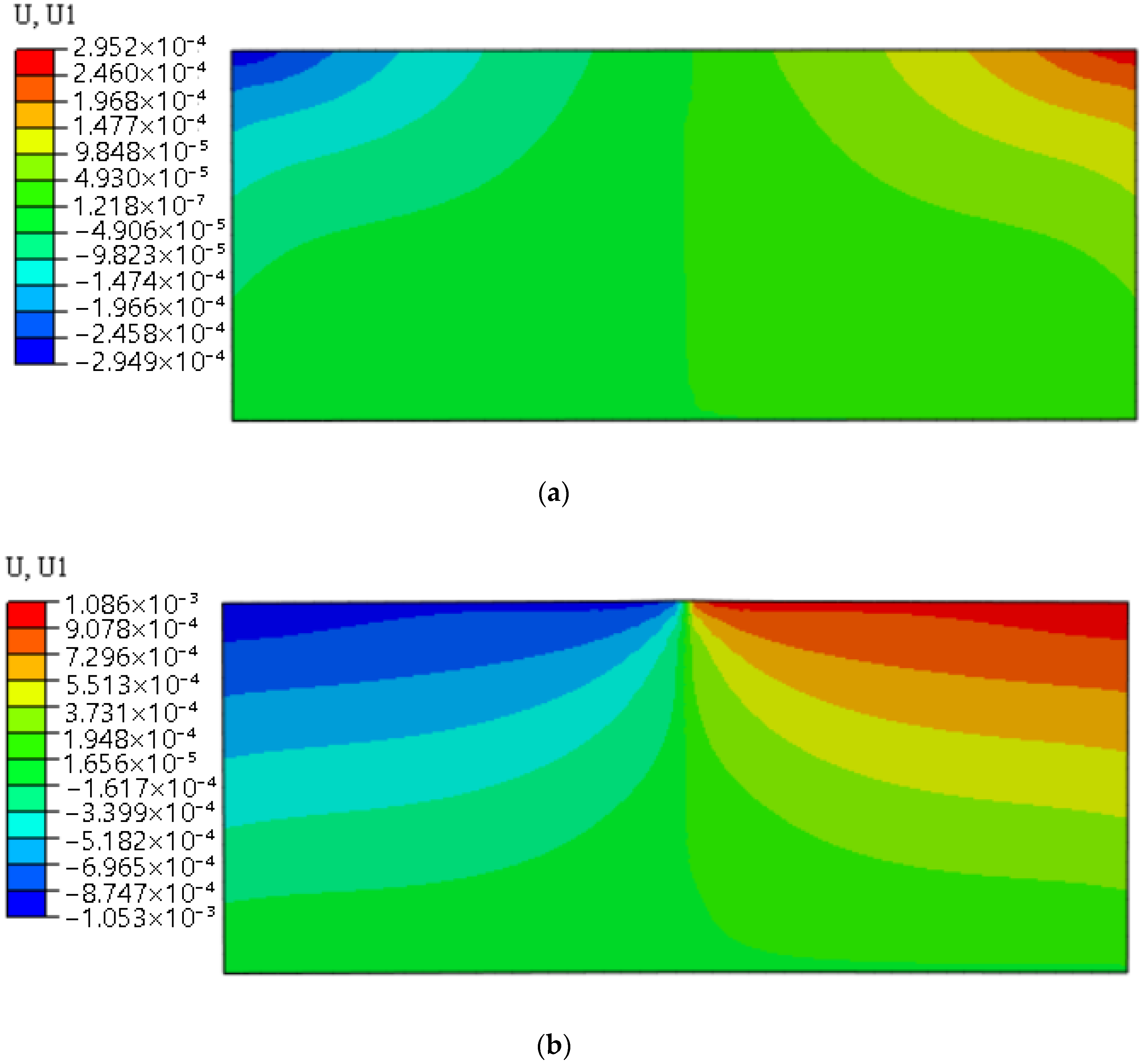
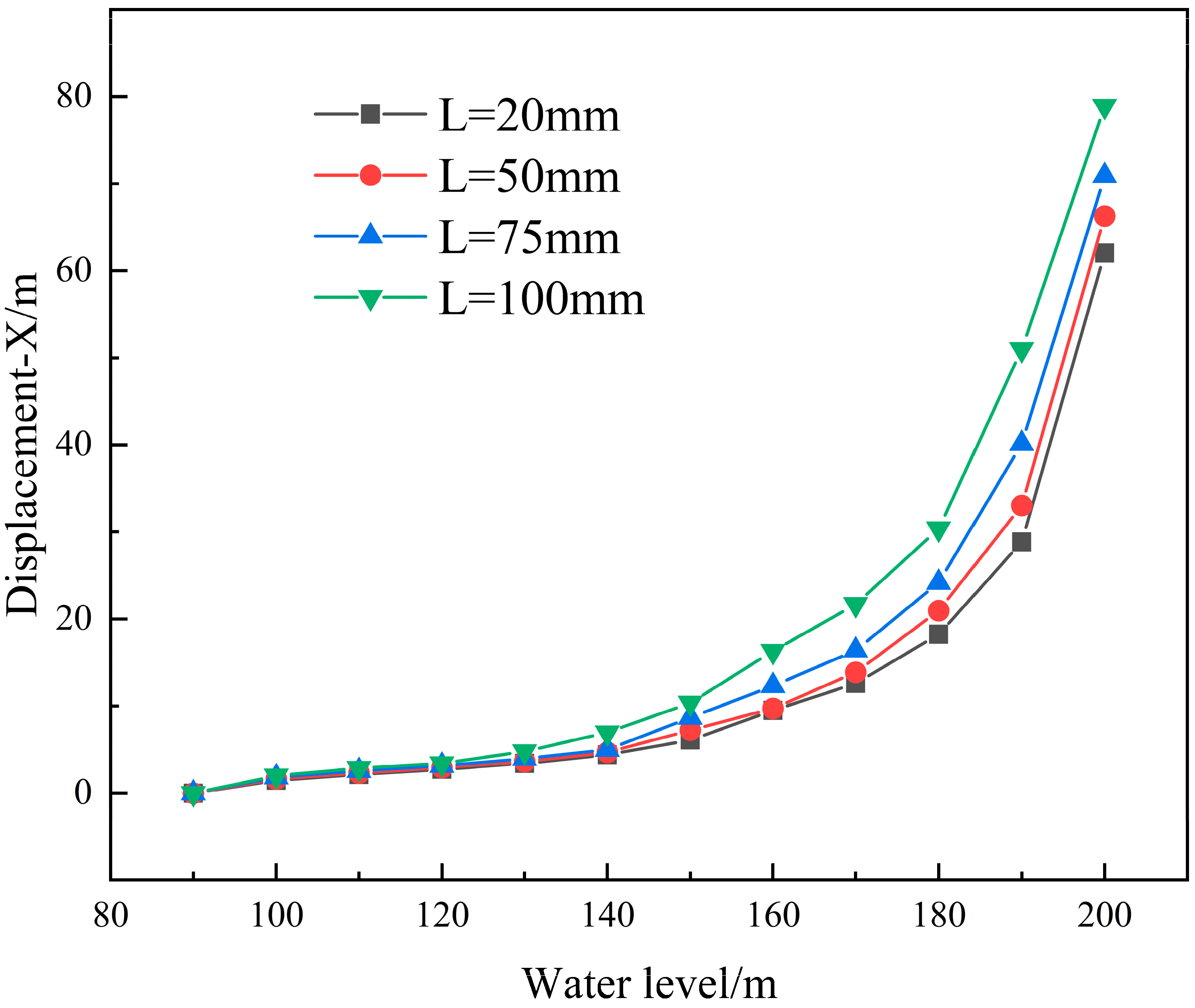
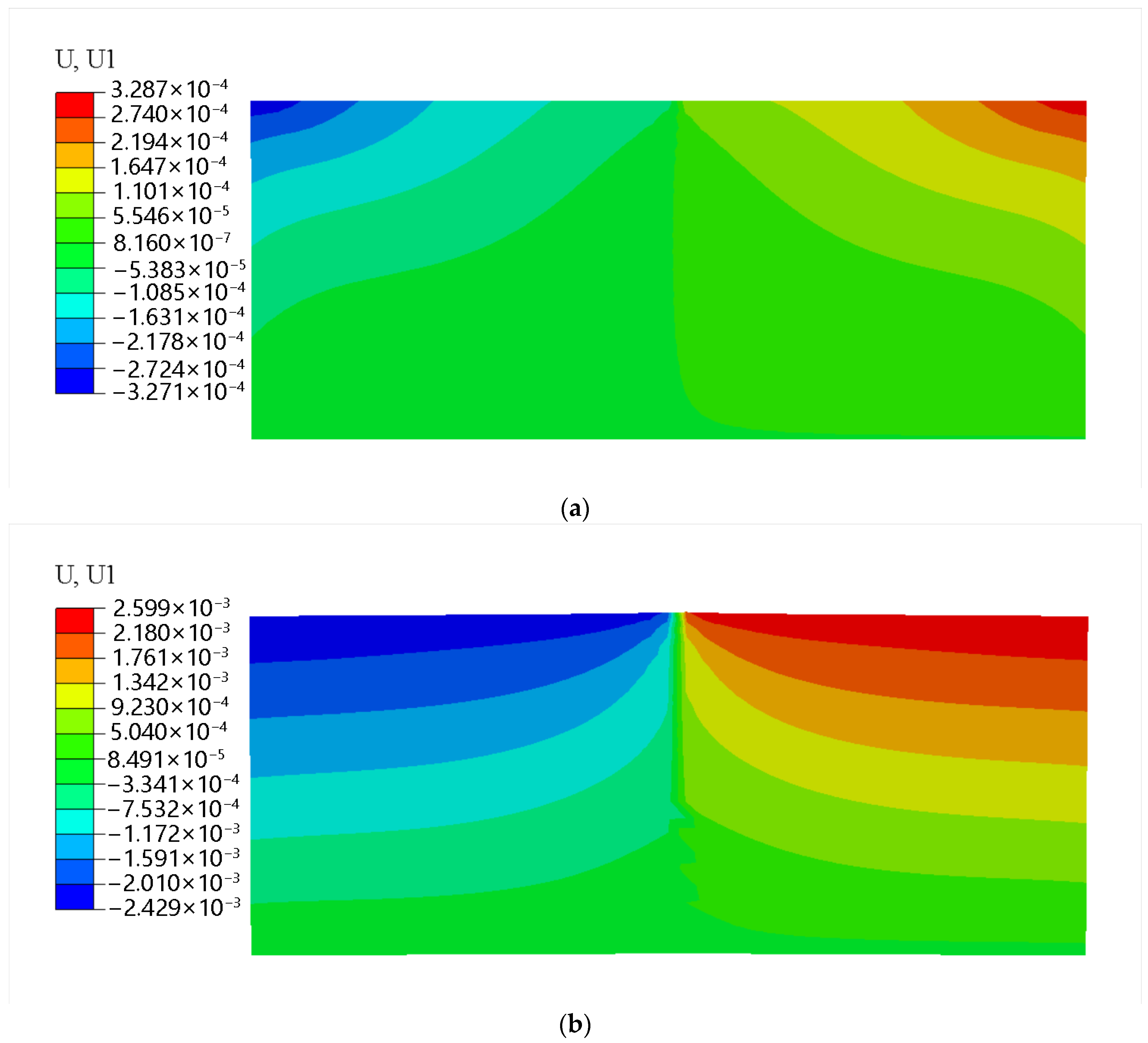
When the initial crack length of the rock formation is 20 mm, the rock formation undergoes hydraulic fracturing as the total water head rises, and the numerical simulation results of the crack opening width are shown in Figure 3; the results of the rock formation crack opening width with different initial crack lengths are presented in Table 2; the relationship curve between the crack opening width and the total water head is displayed in Figure 4. The results indicate that when the total water head rises to approximately 90 m, the initial cracks in the rock formation start to propagate; the corresponding water head heights when crack propagation occurs in rock formation with initial crack lengths of 20 mm, 50 mm, 75 mm, and 100 mm are 97 m, 94 m, 93 m, and 91 m, respectively. As the total water head continues to rise, the crack opening width of the rock formation increases continuously. Specifically, when the water head height is between 90 m and 150 m, the growth rate of the crack opening width is slow; when the water head height is between 150 m and 200 m, the growth rate of the crack opening width increases and tends to accelerate continuously. A possible reason for this is that the rock formation continues to be damaged under the action of water pressure and eventually fractures.
To gain a clearer understanding of the impact of water level height on crack opening width, a nonlinear regression method was used to establish a relevant equation, where the independent variable is the water level height and the dependent variable is the crack opening width. The basic formula based on the univariate nonlinear regression equation is
X = c e k H
In the formula, X is the dependent variable, H is the independent variable, and c and k are the correlation coefficients.
Simplifying the formula into a univariate linear regression equation, we can obtain
y = k H + ln c
In this formula
k ^ = i = 1 n ( H i H ¯ ) ( y i y ¯ ) i = 1 n ( H i H ¯ ) 2
y = ln X
ln c ¯ = y ¯ k ^ · H ¯
Therefore, in the univariate linear regression equation, Table 3 is obtained.
It can be concluded from the table that the y-value increases linearly with the rise in height H. Therefore, by performing a linear fitting on the data in the above table, the following equation can be obtained:
X = 0.0365 e 0.033 H / 1000 ,   98   m < H 200   m ,   L = 20   mm X = 0.042 e 0.0351 H / 1000 ,   94   m < H 200   m ,   L = 50   mm X = 0.0469 e 0.0366 H / 1000 ,   93   m < H 200   m ,   L = 75   mm X = 0.0513 e 0.0367 H / 1000 ,   91   m < H 200   m ,   L = 100   mm
In the formula, X is the crack opening width and H is the water level height.
(2) Crack extension length
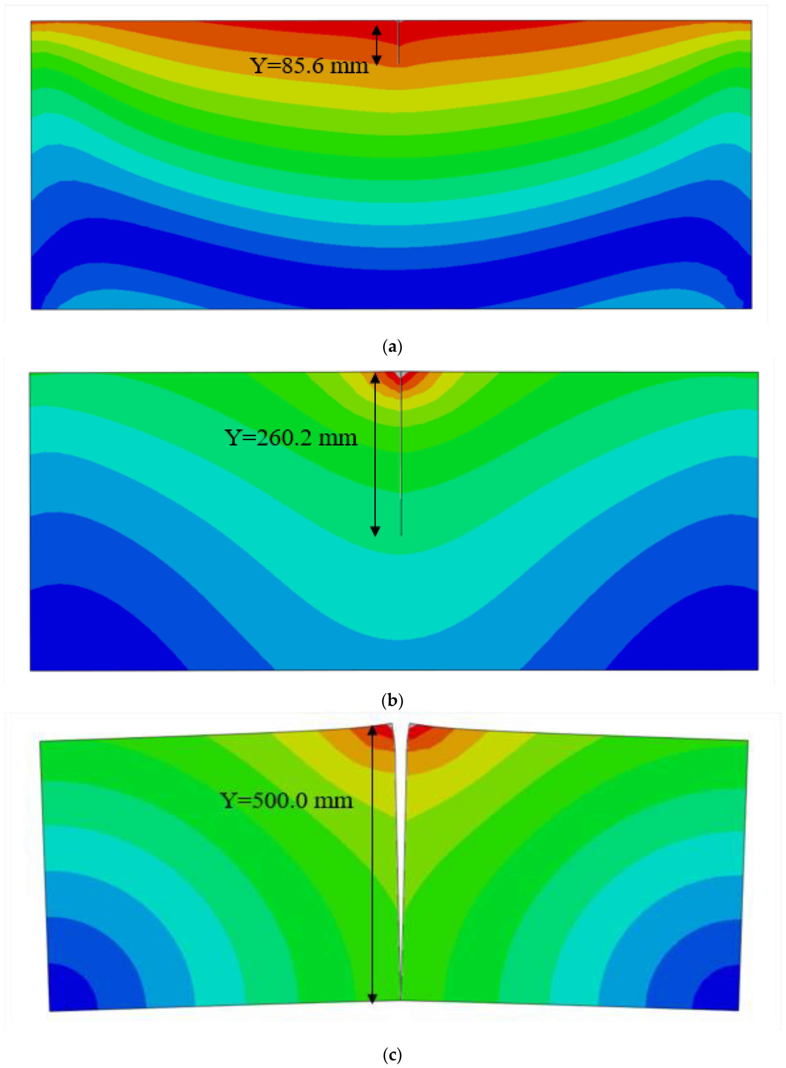
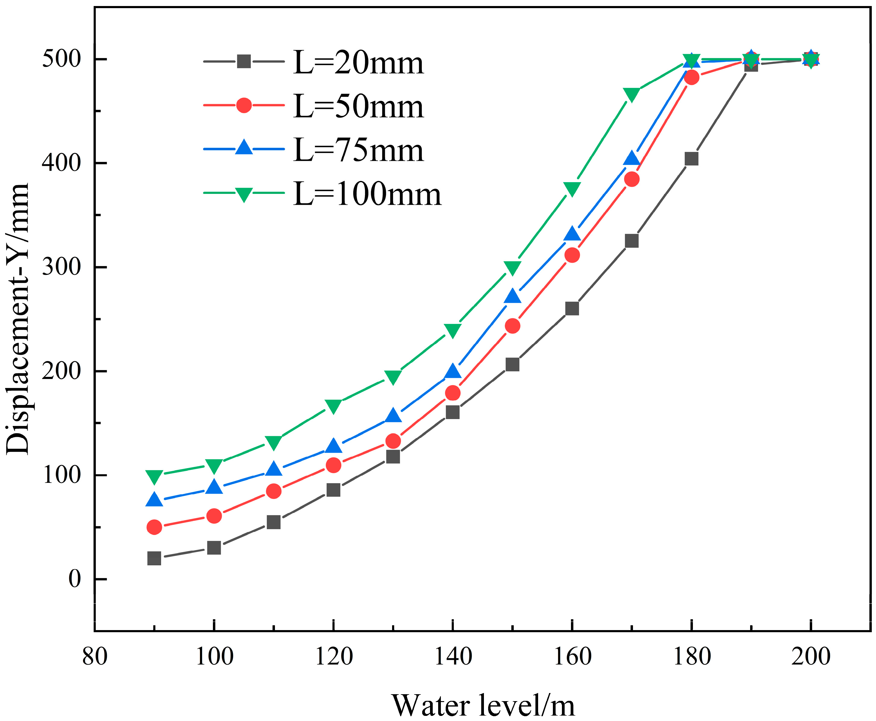
When the initial crack length of the rock formation is 20 mm, the simulation results of the crack extension length are shown in Figure 5; the results of the rock formation crack extension length with different initial crack lengths set are presented in Table 4; the relationship curve between the crack extension length and the total water head height is illustrated in Figure 6. The results indicate that the total water head heights corresponding to the through fracture of rock formation with initial crack lengths of 20 mm, 50 mm, 75 mm, and 100 mm are 192 m, 186 m, 181 m, and 175 m, respectively. Combined with Figure 4 and Figure 6, when different initial crack lengths are set, the extension trends of crack propagation length and opening width are consistent. When the water pressure is low, microcracks develop slowly; once the water pressure reaches a certain level, the crack propagation speed increases rapidly, eventually leading to the failure of the rock formation. Moreover, under the same water pressure, the longer the initial crack in the rock formation, the greater the crack opening width and propagation length caused by the water pressure.
To clearly understand the influence of water level height on the extension length of rock mass cracks, the curves obtained in Figure 6 were subjected to nonlinear fitting, and the following equation was derived:
Y = 2.140 e 0.031 H / 1000 ,   97   m < H 192   m 0.5   m ,   192   m < H 200   m   ,   L = 20   mm Y = 4.953 e 0.026 H / 1000 ,   94   m < H 186   m 0.5   m ,   186   m < H 200   m   ,   L = 50   mm Y = 8.935 e 0.022 H / 1000 ,   93   m < H 181   m 0.5   m ,   181   m < H 200   m   ,   L = 75   mm Y = 12.679 e 0.021 H / 1000 ,   91   m < H 175   m 0.5   m ,   175   m < H 200   m   ,   L = 100   mm
In the formula, X is the crack opening width and H is the water level height.

4.2. Different Rock Formation Dips

The above research mainly focuses on the influence of different initial crack lengths of rock formations on the hydraulic fracturing process. However, in different rock masses, the dip angles of rock formations vary. Therefore, to further understand whether the dip angle of rock formations affects crack propagation during water level rise, the initial crack length of rock formations in the model is set to 20 mm, and the dip angles of the rock formations (θ) are set to 30°, 45°, 60°, and 75°, respectively.
(1) Crack opening width
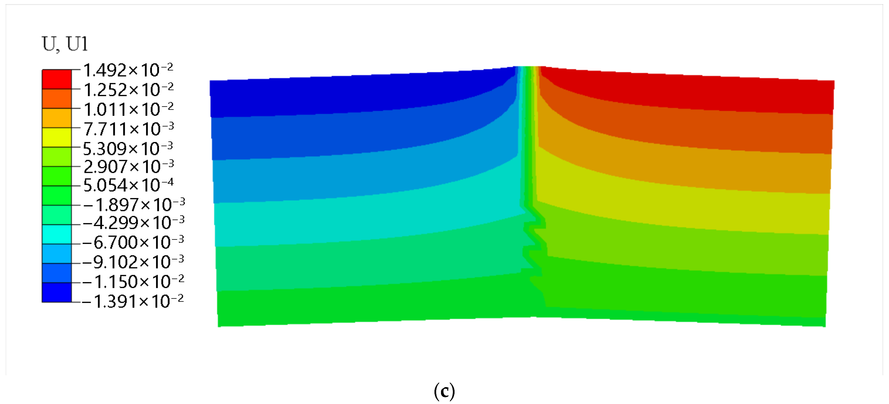
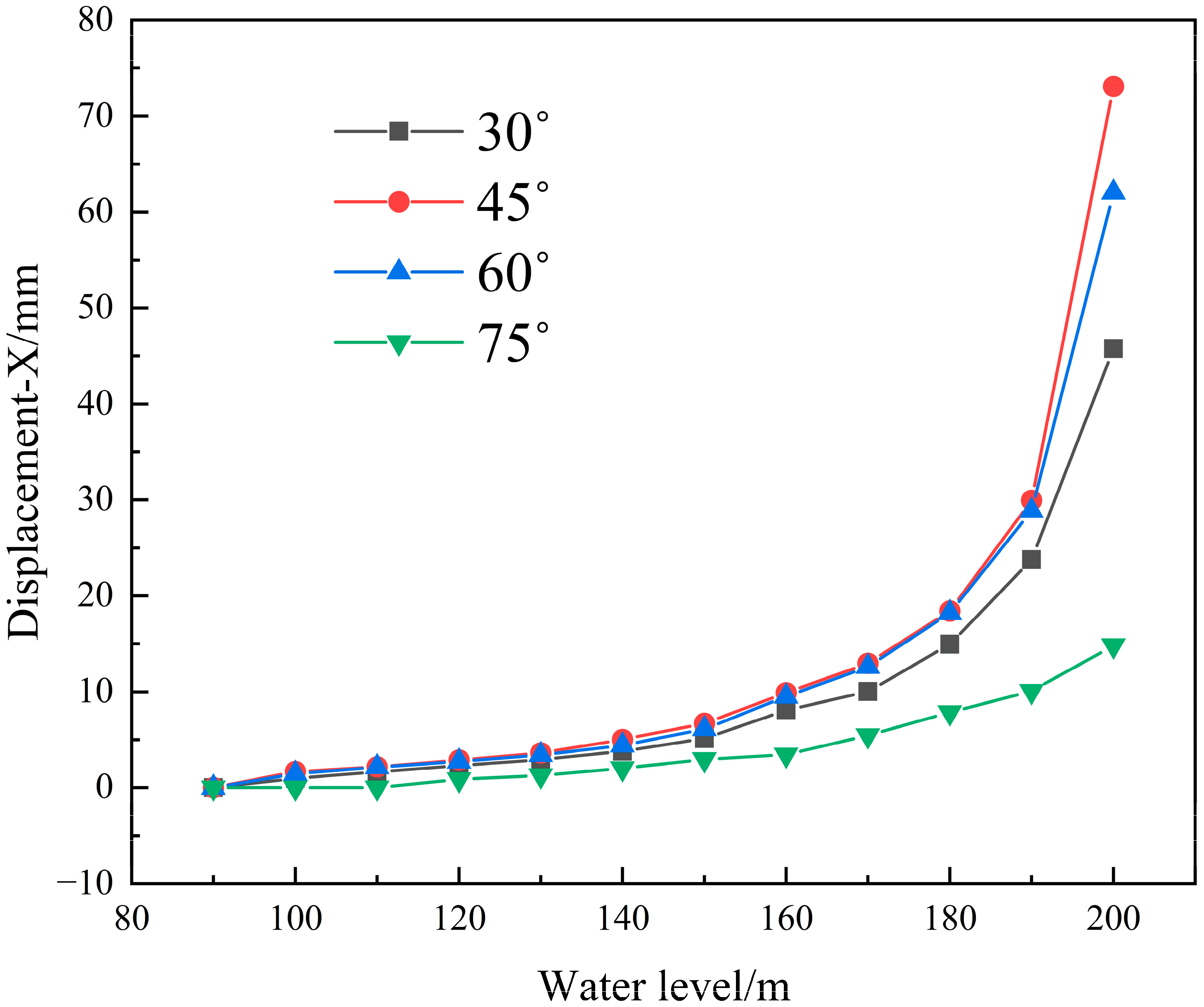
When the rock formation dip angle is 45°, hydraulic fracturing occurs in the rock formation as the total head rises, and the numerical simulation results of the crack opening width are shown in Figure 7; the results of the rock formation crack opening width under different initial rock formation dip angles are shown in Table 5; the relationship curve between the crack opening width and the total head is shown in Figure 8. The results indicate that when the water level reaches approximately 90 m, the rock formations with dip angles of 30°, 45°, and 60° begin to experience crack propagation. The rock formation with a dip angle of 75° requires the maximum water pressure for hydraulic fracturing to occur. A possible reason is that due to the larger dip angle of the rock formation, the component of the self-weight stress of the upper rock mass in the direction perpendicular to the initial crack is larger, which offsets part of the water pressure that causes continuous crack propagation in the rock formation. The water levels corresponding to the crack propagation in the toppling rock masses with dip angles of 30°, 45°, 60°, and 75° are 98 m, 93 m, 97 m, and 112 m, respectively.
To clearly understand the influence of water level height on the crack opening width of rock masses when the rock formation is set at different dip angles, the curves obtained in Figure 8 are subjected to nonlinear fitting, and the following equations are derived:
X = 0.0365 e 0.033 H / 1000 ,   98   m < H 200   m ,   θ = 30 ° X = 0.0758 e 0.03 H / 1000 ,   93   m < H 200   m ,   θ = 45 ° X = 0.0523 e 0.0332 H / 1000 ,   97   m < H 200   m ,   θ = 60 ° X = 0 ,   90   m < H 112   m 0.0137 e 0.0353 H / 1000 ,   112   m < H 200   m ,   θ = 75 °
In the formula, X is the crack opening width and H is the water level height.
(2) Crack extension length
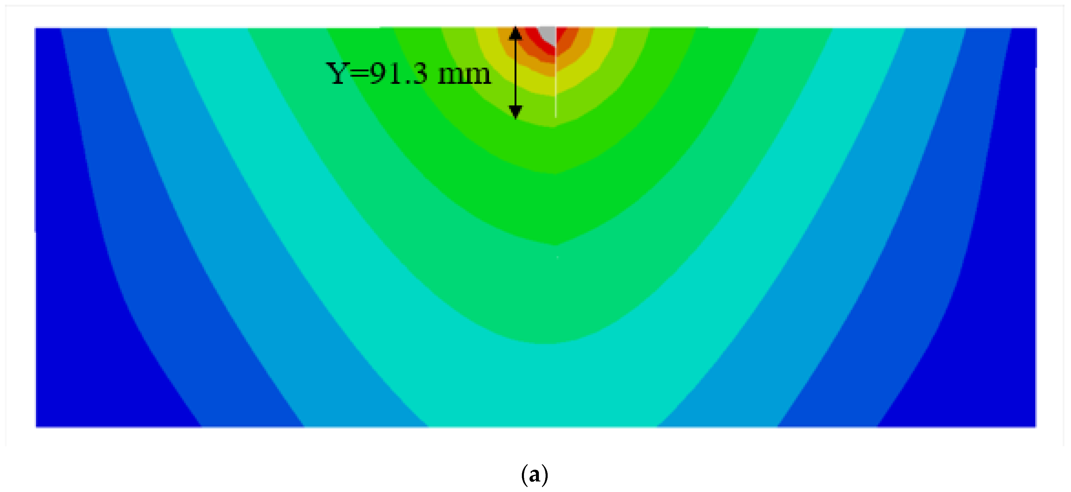
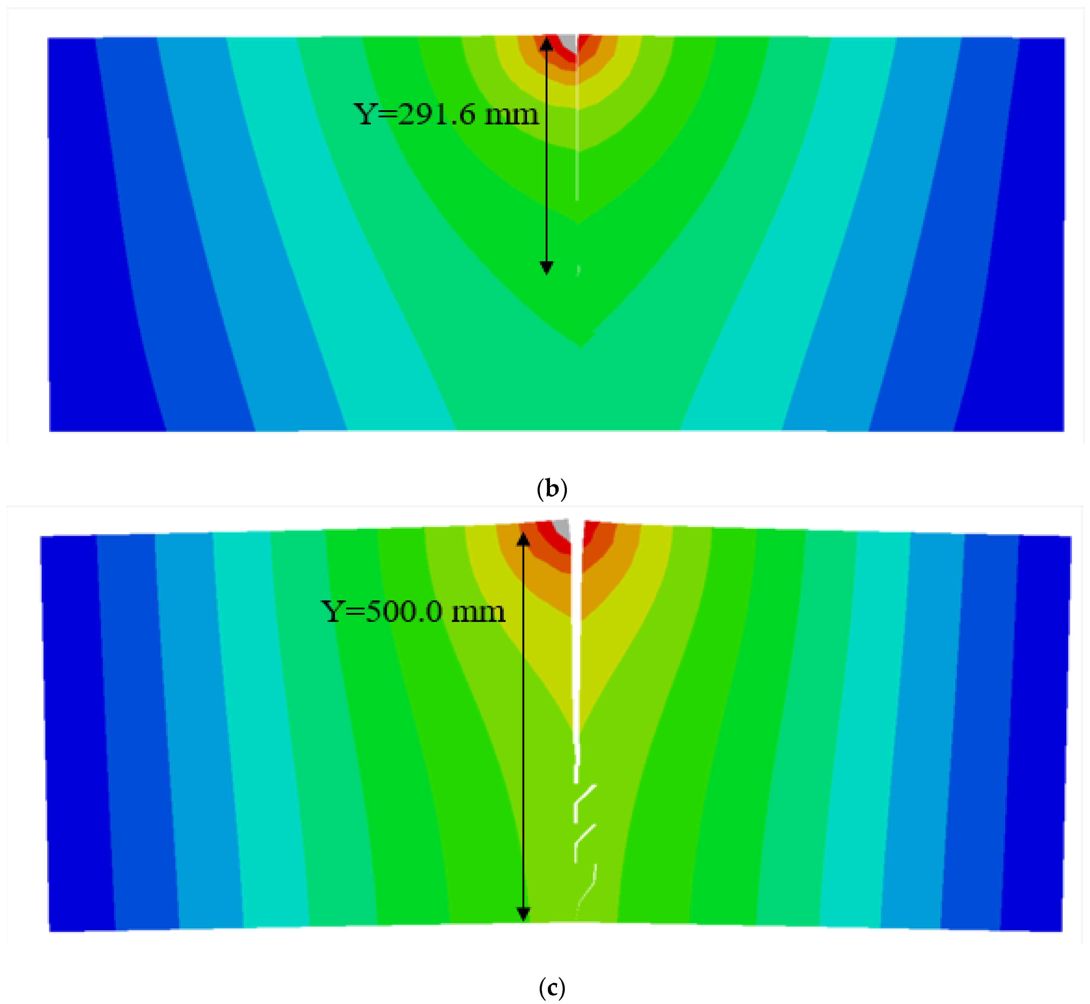
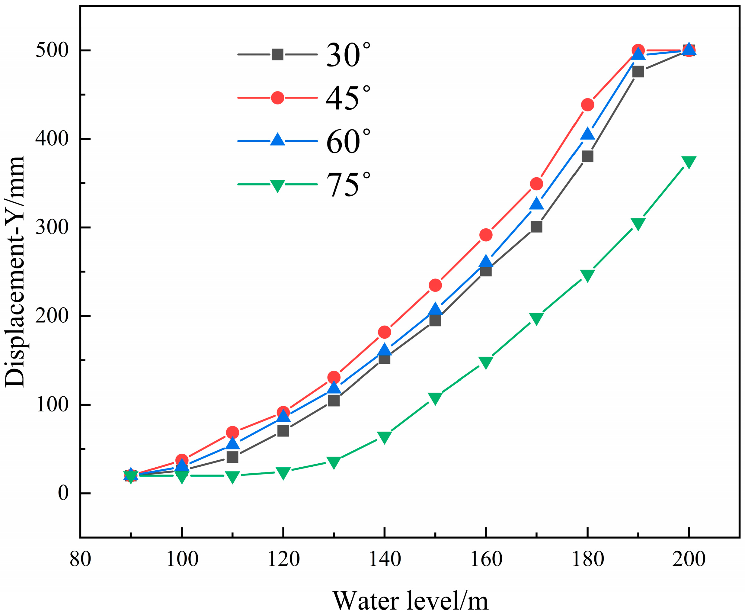
When the rock formation dip angle is 45°, hydraulic fracturing occurs in the rock formation as the total water head rises, and the numerical simulation results of the crack extension length are shown in Figure 9; the results of the rock formation crack extension length under different initial rock formation dip angles are shown in Table 6; the relationship curve between the crack extension length and the total water head is shown in Figure 10. The results show that with the continuous rise in the water level, the extension length of rock formation cracks increases continuously. The water level heights corresponding to the penetration of the toppling rock mass with dip angles of 30°, 45°, and 60° are 198 m, 185 m, and 192 m, respectively, among which the rock formation with a dip angle of 75° does not undergo penetration under the water head pressure of 200 m. By comparing with Figure 8 and Figure 10, it is clear that when different rock formation dip angles are set, the overall expansion trend of rock formation cracks is consistent. When the water pressure is low, microcracks develop slowly; once the water pressure reaches a certain level, the crack expansion speed increases rapidly, eventually leading to the failure of the rock formation. Under the same water pressure, the rock formation with a dip angle of 45° has the maximum degree of crack expansion, and the rock formation with a dip angle close to 90° is not prone to crack expansion.
To clearly understand the influence of water level height on the extension length of rock mass cracks, the curves obtained in Figure 10 were subjected to nonlinear fitting, and the following equation was derived:
Y = 3.935 e 0.028 H / 1000 ,   98   m < H 198   m 0.5   m ,   198   m < H 200   m   ,   θ = 30 ° Y = 4.759 e 0.026 H / 1000 ,   91   m < H 185   m 0.5   m ,   185   m < H 200   m   ,   θ = 45 ° Y = 2.140 e 0.031 H / 1000 ,   93   m < H 192   m 0.5   m ,   192   m < H 200   m   ,   θ = 60 ° Y = 0 ,   90   m < H 112   m 3.353 e 0.024 H / 1000 ,   112   m < H 200   m   ,   θ = 75 °
In the formula, Y is the crack extension length and H is the water level height.

5. Discussion

This paper investigates the variation patterns of crack opening width and propagation length in toppling deformed rock masses under different water pressures through numerical simulation. As no corresponding experimental studies were conducted, the author reviewed the relevant literature to validate the accuracy of the simulation results. Specifically, Reference [35] conducted extensive experiments on the critical water pressure for pre-existing cracks. The results indicate that, when other influencing factors are constant and within a certain range for pre-existing crack width and length, the critical water pressure for crack initiation decreases as the initial width of the pre-existing crack increases. For every 2 mm increase in width, the critical initiation pressure decreases by approximately 20%. When other influencing factors are constant, the critical water pressure for crack initiation decreases with increasing initial crack length. For every 10 mm increase in crack length, the critical water pressure decreases by approximately 35%. This trend is consistent with the numerical simulation results presented in this paper.
This paper still has a number of limitations that need to be acknowledged. This paper only studies the displacement that occurs during crack propagation, and further research is needed on the stress concentration at the crack tip. In the natural state, toppling rock formations often contain multiple natural cracks, and the influence of hydraulic cracks on natural cracks is also a topic worthy of research.

6. Conclusions

Natural cracks are liable to occur in toppling deformed rock masses during the toppling process, and these cracks will continue to expand and extend under the action of water pressure. Based on the basic principles of the extended finite element method (XFEM), taking the toppling deformed rock mass as the research object, this study compares the laws of crack propagation during hydraulic fracturing in toppling rock formations with different initial crack lengths and dip angles when the water level rises, and fits the relevant equations. Considering the self-weight of the toppling rock mass and the water pressure load on the crack surface, by setting different initial crack lengths and rock formation dip angles, the hydraulic fracturing analysis of preset initial cracks in the toppling rock mass is carried out, and the following conclusions can be drawn:
(1) When the water level reaches a certain height, the relatively high water pressure will cause hydraulic fracturing in the toppling rock mass with existing natural cracks. The water level at which hydraulic fracturing occurs is around 100 m. After hydraulic fracturing takes place in the rock mass, as the water level keeps rising, the crack propagation rate is slow first and then fast. When the water pressure is low, microcracks extend slowly; when the water pressure reaches a certain level, the rock formation cracks expand rapidly and eventually fracture.
(2) At the same water level, the initial crack length affects the crack propagation in the rock mass. Rock masses with longer initial cracks are more prone to hydraulic fracturing and more likely to experience penetration. The dip angle of the rock formation is another factor influencing crack propagation. Rock formations with a dip angle of 45° are more susceptible to hydraulic fracturing than those with other dip angles, while rock formations with a dip angle close to 90° hardly undergo hydraulic fracturing.
(3) The instability failure mechanism of hydraulic fracturing in toppling deformed rock masses is tension shear action. The tensile stress at the tip of the rock mass structural plane is the maximum, and water pressure is the main factor causing the tension shear action in the toppling rock mass. As the fissure water pressure rises, the tensile stress at the crack tip will increase sharply. Once new microcracks appear in the initial crack, it will be in an unstable propagation state.

Author Contributions

Conceptualization, H.P. and M.D.; methodology, H.P.; software, H.P.; validation, M.D. and H.P.; formal analysis, H.P.; resources, M.D.; data curation, H.P.; writing—original draft preparation, H.P.; writing—review and editing, M.D.; funding acquisition, H.P. All authors have read and agreed to the published version of the manuscript.

Funding

This research was supported by the Science Foundation of China Huaneng Group Co., Ltd. [20158101216].

Institutional Review Board Statement

Not applicable.

Informed Consent Statement

Not applicable.

Data Availability Statement

Data are contained within the article.

Conflicts of Interest

The authors declare that this study received funding from Science Foundation of China Huaneng Group Co., Ltd. The funder was not involved in the study design, collection, analysis, interpretation of data, the writing of this article or the decision to submit it for publication.

References

  1. Yu, P.; Zhang, Y.; Peng, X. Evaluation of impact force of rock landslides acting on structures using discontinuous deformation analysis. Comput. Geotech. 2019, 114, 103137. [Google Scholar] [CrossRef]
  2. Chen, B.; Barboza, B.R.; Sun, Y.; Bai, J.; Thomas, H.R.; Dutko, M.; Cottrell, M.; Li, C. A review of hydraulic fracturing simulation. Arch. Comput. Methods Eng. 2022, 29, 1–58. [Google Scholar] [CrossRef]
  3. Ismail, A.; Azadbakht, S. A comprehensive review of numerical simulation methods for hydraulic fracturing. Int. J. Numer. Anal. Methods Geomech. 2024, 48, 1433–1459. [Google Scholar]
  4. Liu, X.; Hao, Z.; Liu, S.; Zhang, P.; Pan, Y. Study of fracture behavior in three-dimensional Brazilian disk based on phase field method. J. Dalian Univ. Technol. 2025, 65, 181–190. [Google Scholar]
  5. Zhan, M.L.; Cen, J. Experimental and analytical study on hydraulic fracturing of cylinder sample. Chin. J. Rock Mech. Eng. 2007, 6, 1181–1193. [Google Scholar]
  6. Wang, S.; Li, D.Y.; Mitri, H. Numerical simulation of hydraulic fracture deflection influenced by slotted directional boreholes using XFEM with a modified rock fracture energy. J. Pet. Sci. Eng. 2020, 193, 107375. [Google Scholar] [CrossRef]
  7. Lu, S.F.; Wang, S.W.; Chen, X.J. Natural fractures in soft coal seams and their effect on hydraulic fracture propagation: A field study. J. Pet. Sci. Eng. 2020, 192, 107255. [Google Scholar] [CrossRef]
  8. Ying, Y.; Huang, W.; Ma, Y.; Peng, F. Fracture behavior of periodic porous structures by phase field method. Chin. J. Theor. Appl. Mech. 2022, 54, 3430–3443. [Google Scholar]
  9. Park, B.Y.; Kim, K.S.; Kwon, S. Determination of the hydraulic conductivity components using a there–dimensional fracture network model in volcanic rock. Eng. Geol. 2002, 66, 127–141. [Google Scholar]
  10. Azarov, A.; Patutin, A.; Serdyukov, S. Hydraulic fracture propagation near the cavity in a poroelastic media. Appl. Sci. 2021, 11, 11004. [Google Scholar] [CrossRef]
  11. Liu, Y.; Hu, Y.; Kang, Y. The propagation of hydraulic fractures in a natural fracture network: A numerical study and its implications. Appl. Sci. 2022, 12, 4738. [Google Scholar] [CrossRef]
  12. Tang, X.; Wan, W.; Lu, Z.; Chen, W. Study on composite fracture characteristics and hydraulic fracturing behavior of hard rock. Appl. Sci. 2024, 14, 2585. [Google Scholar] [CrossRef]
  13. Liu, T.; Sheng, Y.; Li, Q.; Zhang, C.; Cui, M.; Yu, Z.; Cao, P. Hydraulic fracture propagation in fractured rock mass. Appl. Sci. 2022, 12, 5846. [Google Scholar] [CrossRef]
  14. Huang, Y.; Zhou, L.T.; Zhou, Z.F. Equations for permeability variation of fractured rock mass under high water pressure. J. Eng. Geol. 2018, 26, 1433–1438. [Google Scholar]
  15. Li, D.Q.; Li, Z.L.; Lv, C.C. Analysis of fracture strength of rock mass considering fissure additional water pressure. Rock Soil Mech. 2018, 39, 3174–3180. [Google Scholar]
  16. Zhang, J.; Qin, G.; Wang, B. Study on elastoplastic damage and crack propagation mechanisms in rock based on the phase field method. Appl. Sci. 2025, 15, 6206. [Google Scholar] [CrossRef]
  17. Hu, S.W.; Wang, Y.; Sun, Y.Y.; Lu, J. Analysis of structure deformation of gravity dam under hydraulic fracturing. J. Water Resour. Archit. 2020, 18, 234–241. [Google Scholar]
  18. Liu, B.; Jin, Y.; Chen, M. Influence of vugs in fractured–vuggy carbonate reservoirs on hydraulic fracture propagation based on laboratory experiments. J. Struct. Geol. 2019, 124, 143–150. [Google Scholar] [CrossRef]
  19. Huang, W.; Wang, H.; Zhang, T.; He, M.; Yan, L. Hydraulic pressure effect on mechanical properties and permeabilities of layered rock mass: An experimental study. Eur. J. Environ. Civ. Eng. 2020, 27, 2422–2433. [Google Scholar] [CrossRef]
  20. Liu, W.; Liu, Y.; Yao, X.; Chu, J.; Chen, X.; Tan, Z. Study on breakdown pressure in hydraulic fracturing process of hard rock based on numerical simulation. Geotech. Geol. Eng. 2021, 39, 909–917. [Google Scholar] [CrossRef]
  21. Zhang, W.; Shen, Z.; Xu, L.; Zhang, H.; Gan, L.; Li, G. A phase-field fracture model for brittle materials based on COMSOL. Chin. J. Comput. Mech. 2023, 40, 273–280. [Google Scholar]
  22. Liu, J.; Xue, Y.; Gao, F.; Teng, T.; Liang, X. Propagation of hydraulic fractures in bedded shale based on phase-field method. Chin. J. Geotech. Eng. 2022, 44, 464–473. [Google Scholar]
  23. Zhao, H.J.; Ma, F.S.; Guo, J. Investigation of hydraulic fracturing mechanism by using a coupled continuous–discontinuous hydromechanical model. IOP Conf. Ser. Earth Environ. Sci. 2020, 570, 042042. [Google Scholar] [CrossRef]
  24. Cao, Z.; Wang, Y.; Lin, H.; Sun, Q.; Wu, X.; Yang, X. Hydraulic fracturing mechanism of rock mass under stress-damage-seepage coupling effect. Geofluids 2022, 2022, 5241708. [Google Scholar]
  25. Mao, S.; Li, G.S. Extended finite element modeling of hydraulic fracture propagation. Eng. Mech. 2014, 31, 123–125. [Google Scholar]
  26. Yu, Y.; Liu, J.; Li, B.; Sun, Y. Analysis of the hydraulic fracturing mechanism and fracture propagation law with a new extended finite element model for the silty hydrate reservoir in the South China Sea. J. Nat. Gas Sci. Eng. 2022, 101, 104535. [Google Scholar] [CrossRef]
  27. Zheng, A.X.; Luo, X.Q.; Chen, Z.H. Hydraulic fracturing coupling model of rock mass based on extended finite element method. Rock Soil Mech. 2019, 40, 799–808. [Google Scholar]
  28. Zheng, A.X.; Luo, X.Q. An extended finite element method for modeling hydraulic fracturing in perilous rock. Rock Soil Mech. 2018, 39, 3461–3468. [Google Scholar]
  29. Shi, Y.K.; Huo, J.Y.; Zhang, D.X. Hydraulic fracturing analysis of concrete gravity dam based on extend finite element method. Sci. Technol. Eng. 2022, 22, 2069–2075. [Google Scholar]
  30. Hu, Y.F. Hydraulic fracturing analysis of hydraulic pressure tunnel based on extended finite element method. Adhesion 2024, 51, 160–164. [Google Scholar]
  31. Gao, J.Q.; Zheng, A.X.; Mao, Q. Hydraulic fracturing analysis of gravity dam based on extended finite element method. Water Resour. Power 2018, 36, 95–97. [Google Scholar]
  32. Li, S.Y.; He, T.M.; Yin, X.C. Introduction to Rock Fracture Mechanics; University of Science and Technology of China Press: Hefei, China, 2010. [Google Scholar]
  33. Fleming, M.; Chu, Y.A.; Moran, B. Enriched element free Galerkin Methods for crack tip fields. Int. J. Numer. Methods Eng. 1997, 40, 1483–1504. [Google Scholar] [CrossRef]
  34. Waltersalters, M.C.; Paulino, G.H.; Dodds, R.H. Interaction integral procedures for 3-D curved cracks including surface tractions. Eng. Fract. Mech. 2005, 72, 1635–1663. [Google Scholar] [CrossRef]
  35. Liu, D.T.; Shen, Z.Z. Experimental study on critical internal water pressure of hydraulic fractured rock mass. South North Water Transf. Water Sci. Technol. 2018, 16, 140–145. [Google Scholar]
Figure 1. Nodes requiring reinforcement near structural planes.
Applsci 15 10177 g001
Figure 2. Geometry model.
Applsci 15 10177 g002
Figure 3. Cloud map of crack opening width: (a) Scheme 1 (L = 20 mm, H = 100 m, θ = 60°); (b) Scheme 2 (L = 20 mm, H = 120 m, θ = 60°); (c) Scheme 3 (L = 20 mm, H = 160 m, θ = 60°).
Applsci 15 10177 g003aApplsci 15 10177 g003b
Figure 4. Graph of relationship between crack opening width (X) and water level.
Applsci 15 10177 g004
Figure 5. Cloud map of crack extension length. (a) Scheme 1 (L = 20 mm, H = 120 m, θ = 60°); (b) Scheme 2 (L = 20 mm, H = 160 m, θ = 60°); (c) Scheme 3 (L = 20 mm, H = 200 m, θ = 60°).
Applsci 15 10177 g005
Figure 6. Graph of relationship between crack extension length (Y) and water level.
Applsci 15 10177 g006
Figure 7. Cloud map of crack opening width. (a) Scheme 1 (θ = 45°, H = 100 m, L = 20 mm); (b) Scheme 2 (θ = 45°, H = 140 m, L = 20 mm); (c) Scheme 3 (θ = 45°, H = 180 m, L = 20 mm).
Applsci 15 10177 g007aApplsci 15 10177 g007b
Figure 8. Graph of relationship between crack opening width (X) and water level.
Applsci 15 10177 g008
Figure 9. Cloud map of crack extension length. (a) Scheme 1 (θ = 45°, H = 120 m, L = 20 mm); (b) Scheme 2 (θ = 45°, H = 160 m, L = 20 mm); (c) Scheme 3 (θ = 45°, H = 200 m, L = 20 mm).
Applsci 15 10177 g009aApplsci 15 10177 g009b
Figure 10. Graph of relationship between crack extension length (Y) and water level.
Applsci 15 10177 g010
Table 1. Model parameters.
Permeability Coefficient (m∙s−1)Fluid Specific Weight (N∙m−3)Porosity RatioFracture Energy (N∙m−1)Tensile Strength (MPa)Elastic Modulus (GPa)Poisson’s RatioVolumetric Weight (KN∙m−3)
1 × 10−898000.180001.518.50.32.5 × 104
Table 2. Table of crack opening width results.
H/m
L/mm 90100110120130140150160170180190200
20X/mm01.452.142.733.424.416.119.5012.6218.2328.8562.04
50X/mm01.622.312.943.634.707.229.7113.8920.9633.0366.30
75X/mm01.832.553.153.955.008.6712.3216.3924.1740.1570.91
100X/mm02.012.873.404.816.9510.3716.3121.7030.3750.9978.94
Table 3. Table of y results.
H/m
L/mm 100110120130140150160170180190200
20X/mm1.452.142.733.424.416.119.5012.6218.2328.8562.04
y0.370.761.001.231.481.812.252.542.903.364.13
50X/mm1.622.312.943.634.707.229.7113.8920.9633.0366.30
y0.480.831.081.291.551.982.272.633.043.504.19
75X/mm1.832.553.153.955.008.6712.3216.3924.1740.1570.91
y0.600.941.151.371.612.162.512.803.193.694.26
100X/mm2.012.873.404.816.9510.3716.3121.7030.3750.9978.94
y0.701.051.221.571.942.342.793.083.413.934.37
Table 4. Table of crack extension length results.
H/m
L/mm 90100110120130140150160170180190200
20Y/mm20.030.154.785.6117.7160.3206.3260.2325.2404.2494.3500.0
50Y/mm50.060.884.6109.6132.8179.1243.5311.6384.7482.5500.0500.0
75Y/mm75.087.1104.3126.6155.8198.4270.6330.4403.1496.7500.0500.0
100Y/mm100.0110.2132.9167.8195.7240.6300.8376.7467.3500.0500.0500.0
Table 5. Table of crack opening width results.
H/m
θ 90100110120130140150160170180190200
30°X/mm00.971.672.312.933.815.148.0910.0114.9623.7645.77
45°X/mm01.692.182.893.625.036.709.8912.9718.4129.9773.11
60°X/mm01.452.142.733.424.416.119.5012.6218.2328.8562.04
75°X/mm0000.881.272.012.973.455.477.8610.0814.82
Table 6. Table of crack extension length results.
H/m
θ 90100110120130140150160170180190200
30°Y/mm20.025.840.970.6104.6152.3194.8251.2300.8380.3475.9500.0
45°Y/mm20.037.268.691.3130.6181.7234.8291.6349.3438.6500.0500.0
60°Y/mm20.030.154.785.6117.7160.3206.3260.2325.2404.2494.3500.0
75°Y/mm20.020.020.024.336.464.8108.7148.9198.6247.3305.6375.5
Disclaimer/Publisher’s Note: The statements, opinions and data contained in all publications are solely those of the individual author(s) and contributor(s) and not of MDPI and/or the editor(s). MDPI and/or the editor(s) disclaim responsibility for any injury to people or property resulting from any ideas, methods, instructions or products referred to in the content.