Article

Silicone Replication Technology Reveals HPWJ Hole Formation Mechanisms

1
School of Emergency Management and Safety Engineering, North China University of Science and Technology, Tangshan 063210, China
2
Tangshan Key Laboratory of Mine Safety and Emergency Management, Tangshan 063210, China
*
Author to whom correspondence should be addressed.
Appl. Sci. 2025, 15(18), 10132; https://doi.org/10.3390/app151810132
Submission received: 14 August 2025 / Revised: 9 September 2025 / Accepted: 11 September 2025 / Published: 17 September 2025
(This article belongs to the Special Issue Coalbed Degassing Method and Technology)

Abstract

We reconstructed the morphology of holes using silicone replication technology, and inverted the hole parameters to reveal the law of high-pressure water jet (HPWJ) hole formation under multi-field coupling. The results show that under the multi-field coupling effects, the evolution of the hole exhibits stage-wise characteristics; in the rapid expansion phase, the hole extends rapidly and deeply, forming a “wedge” pattern, and in the stabilization adjustment phase, the rate of hole expansion slows down, and the hole morphology shifts towards an “elliptical” or “teardrop-shaped” form. However, an increase in confining pressure inhibits the transformation of the hole morphology, and as a result, the “wedge-shaped” characteristics of the hole become more pronounced. With constant confining pressure, increased jet pressure significantly enhances both hole depth and volumetric average extension rate, exhibiting a positive correlation. Conversely, with constant jet pressure, increased confining pressure significantly decreases both hole depth and volumetric average extension rate, exhibiting a negative correlation. Based on silicone replication technology, we established a mapping relationship between ‘pore morphology-jet flow and environmental parameters’ which can be used to evaluate the pressure relief and permeability enhancement effects in deep low-permeability coal seams. By optimizing jet parameters, we can expand the scope of pressure relief and permeability improvement in coal seams, thereby enhancing gas drainage efficiency.

1. Introduction

China boasts abundant deep coal seam resources, yet the management of gas hazards and the safe extraction of these reserves are constrained by high in situ stress, elevated gas pressure, and low permeability characteristics [1,2,3]. High-pressure water jet pressure relief and permeability enhancement technology have become among the primary methods for gas control in deep coal seams due to the high efficiency in breaking coal and significant pressure relief effects [4,5,6,7]. The quantitative characterization of water jet-induced holes is crucial for optimizing construction parameters in hydraulic coal seam gas control. Currently, both laboratory experiments and on-site engineering techniques struggle to accurately quantify the hole-forming effects of water jet impacts. This absence of precise correlation between jet parameters and hole characteristics severely limits the precise regulation of coal breaking efficiency [8,9,10,11].
In recent years, numerous experts and scholars have conducted in-depth research on the law governing hole formation through high-pressure water jets breaking coal, achieving fruitful results: Ge Z et al. analyzed the failure modes of coal rocks and changes in pore structures using scanning electron microscopy, CT, and nuclear magnetic resonance techniques, yet these methods failed to reflect the influence of actual in situ stress (confining pressure) within coal seams [12]. Lei Z et al. establish a numerical model for hole formation through water jet impact breaking coal-rock based on viscoelastic–plastic theory and the material point method, and conducted research on the mechanisms and influencing factors of water jet rock breaking and hole formation in deep coal seams; however, the establishment of the model could not accurately simulate the mechanical performance characteristics of coal-rock materials [13]. Xiao S et al. established a numerical simulation of a pulsed water jet impacting rock masses under different operating parameters based on the SPH-FEM coupled algorithm, revealing the internal damage and failure mechanisms within the rock mass; however, numerical simulations may encounter issues such as mesh distortion and element embedding, making it challenging to accurately simulate the entire process of coal-rock fracture under external forces [14,15]. Xue at al. conducted a comparative study on the fracture mechanism of coal bodies under high-pressure water jets and abrasive water jet impacts, validated through CT scanning experiments; however, their research still exhibits discrepancies between model scale and engineering practice [16]. Zhang at al. demonstrated through theoretical modeling, numerical simulation, and field experiments that High-Pressure Abrasive Water Jet (HPAWJ) flushing technology can effectively enhance coal seam permeability. However, their study was conducted under specific environmental conditions with a relatively simplistic model, and the high-pressure pipelines and nozzles in the experimental setup suffered from severe wear [17]. Zhou at al. analyzed the rock fracture and damage behavior under laser drilling through experimental analysis and numerical simulation verification. However, in underwater conditions, liquid impedes laser energy transmission, resulting in low coal-breaking efficiency, coupled with high operational and maintenance costs for the equipment [18]. Compared with abrasive jet and laser drilling technologies, high-pressure water jets offer advantages including cleanliness, low cost, and reduced energy consumption.
Current studies are constrained by numerical models and laboratory physical conditions, making it difficult to fully and authentically replicate the entire process of fracture separation in coal-rock masses and hole development, as well as changes. As a result, the characteristics and patterns of hole formation during water jet breaking of coal-rock remain unclear, which hinders the widespread application of hydraulic technologies for mitigating coal seam gas disasters. This paper innovatively employs silicone replication technology [19,20], visually demonstrating the dynamic evolution process of hole formation during water jet impact breaking of coal and rock masses under synergistic effects of different parameters (such as jet pressure and confining pressure). It reveals both the energy transfer path of the jet and the development patterns of hole growth. We established a mapping relationship between ‘hole morphology-jet and environmental parameters’, optimized jet parameters to enhance hole formation efficiency, and provide a quantitative basis for evaluating the effectiveness of hydraulic pressure relief and permeability improvement in low-permeability coal seams.

2. Materials and Methods

2.1. Similar Material Sample Preparation

It is difficult for raw coal samples from deep coal seams to meet the requirements of jet fracturing hole-forming experiments in terms of integrity, dimensional specifications, and operational convenience during experimentation. We selected deep coal seams buried at depths exceeding one kilometer (marked as 1#, 2#, and 3# in Table 1, below) [21,22,23] as representative samples. Based on the average values of their mechanical parameters, including compressive strength, elastic modulus, cohesion, and Poisson’s ratio, we prepared similar material specimens simulating the coal mass. Similar material specimens can effectively characterize the key mechanical properties of deep coal and rock masses during their elastic–plastic deformation phase, as well as the complete stress–strain response throughout the jet impact fracturing process. The mechanical performance parameters of the deep coal seam are presented in Table 1.
Referring to the preparation experience of our predecessors [24,25,26,27], coal powder, cement, sand, and sodium humic acid were combined in specific proportions to fabricate similar material specimens. Using the HTBW-1 type elastic modulus testing machine (with a measurement accuracy range of ±5%, Jinan Mining and Rock Test Instrument Co., Ltd., Jinan, China), uniaxial compression tests were conducted on standard cylindrical specimens with an aspect ratio of 1:2 to determine mechanical parameters including compressive strength, elastic modulus, and Poisson’s ratio. The GranuDrum (Cohesion Strength Tester, Jinan Taichang Instruments Co., Ltd., Jinan, China) powder shear performance analyzer was employed to measure the cohesion of samples (with a measurement accuracy range of ±5%). For each mix proportion scheme, ten sets of specimens were fabricated and the average values of the measured results are presented in Table 2, below.
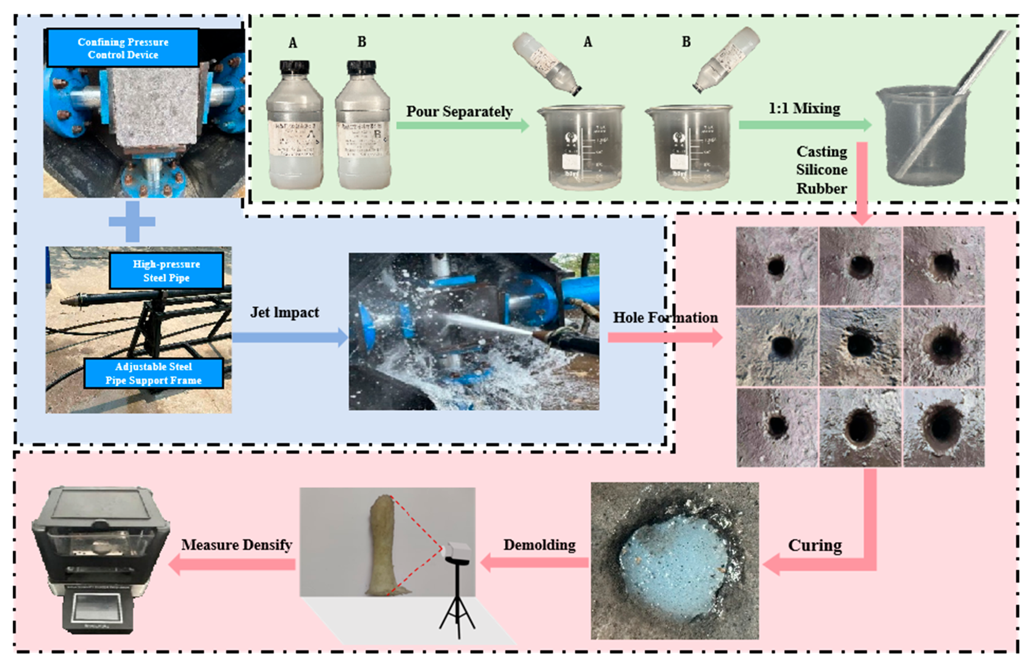
Based on similarity theory and principles [28,29,30], we prepared water jet perforation test specimens using the mix proportion scheme (No. 1), adding deionized water at a ratio of 35% relative to the total material mass, followed by thorough mixing until homogeneity was reached. We poured the mixture into a mold (dimensions: 250 mm × 250 mm × 250 mm), allowed it to air-dry and cure naturally, and then demolded it. The specific fabrication process is shown in Figure 1.

2.2. High-Pressure Water Jet Experimental Platform

The high-pressure water jet experimental platform is composed of a high-pressure water jet perforation device and a newly integrated surrounding rock stress simulation system. The water jet punching device mainly includes a water storage tank, an electric motor, a high-pressure water pump, high-pressure pipelines, pipeline supports, and a jet nozzle. The jet pipe system is mainly composed of stainless steel pipes, high-pressure hoses, and jet nozzles connected together. The integrated surrounding rock stress simulation system is primarily composed of a hydraulic control module, hydraulic pump, electric motor, hydraulic oil tank, hydraulic cylinder, push rod, positioning baffle plate, device fixing bracket, positioning card slot, and guide rail. The hydraulic cylinder features a cross-shaped structure. The hydraulic control module can independently control the push rods in four directions and the positioning baffles, enabling precise and stable pressure control in various orientations. The main parameters of the device are listed in Table 3, and its primary structure is depicted in Figure 2.

2.3. Jet Perforation Experiment

Water jet hole formation is influenced by various factors (nozzle diameter, standoff distance, jet pressure, confining pressure conditions, and time), with practical engineering applications primarily focusing on the effects of three critical parameters—jet pressure, confining pressure, and duration—on jet-induced cavity evolution [31]. Based on previous studies and combined with water jet impact force testing experiments, the standoff distance corresponding to the maximum jet impact force under identical parameter combinations was selected. It was finally determined that when the jet pressures were 10 MPa, 15 MPa, and 20 MPa, the optimal standoff distances were sequentially 1.2 m, 1.5 m and 1.8 m [32]. We conducted large-scale water jet impact fragmentation experiments under varying parameters, and observed and recorded the jet perforation parameters (depth, external diameter) along with the evolutionary process of hole morphology. For specific experimental parameter values, please refer to Table 4. The jet pressure and confining pressure in the following table were measured by pressure gauges, with a measurement error range of ±0.1 MPa for both the confining pressure and jet pressure parameters.

2.4. Silicone Replication Technology Experiment

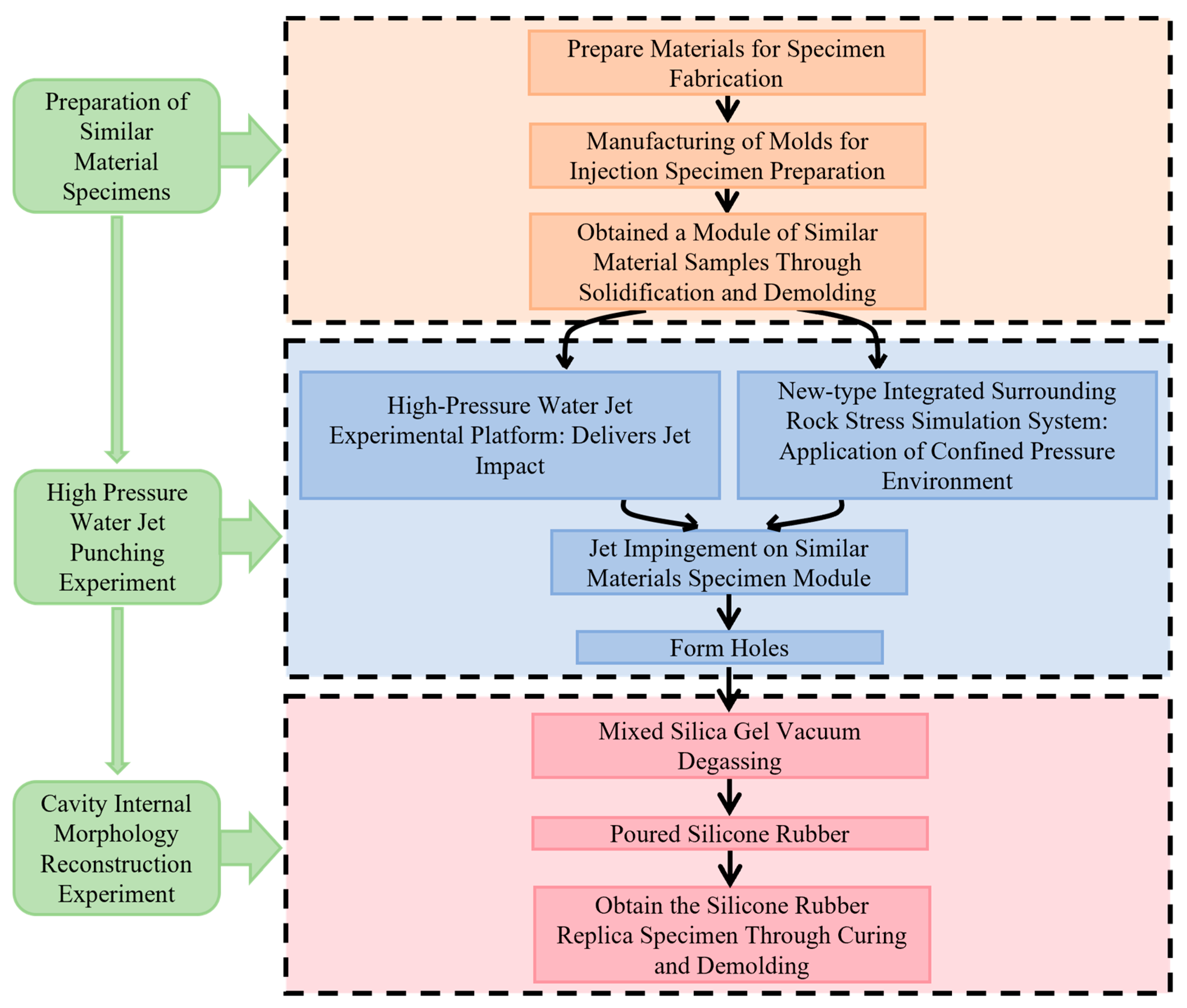
We selected two-component AB silicone rubber as the material for replicating hole morphology. We used SJ3220 type two-component AB silicone rubber (Component A is the base gum, with vinyl polysiloxane as its main component; Component B is the curing agent, with hydrogen-containing silicone oil as its main component). We measured Components A and B (curing agent) in a volume ratio of 1:1 into a clean beaker, thoroughly stirred, and mixed with a glass rod, while performing synchronous vacuum degassing treatment to eliminate microscopic voids within the adhesive matrix, ensuring replication precision. The degassed silicone gel was slowly poured into the jet-formed porous cavity, with synchronous vibration compaction applied during the casting process to eliminate air bubbles in the mixed liquid and enhance the dense adhesion between the silicone gel and the inner wall of the cavity. Subsequently, we allowed it to cure at room temperature for 24 h. After the silicone gel had been fully cured, we separated it while ensuring complete demolding, thereby obtaining a duplicated silicone mold with jet-impact holes.
We weighed the prepared duplicated mold body using a high-precision electronic balance. We employed the TWS-300A Solid Material Density Tester (Matsuhaku TWS-300A, with a measurement accuracy of 0.001 g/cm3, Suzhou Quantum Instruments Co., Ltd., Suzhou, China) to measure the apparent density, placed the colloidal sample into the tester, added liquid (which can be replaced based on the properties of the sample under test), obtained the weighed value of the colloidal sample in the liquid, and calculated the volume of the colloidal sample equivalent to the void volume according to Archimedes’ principle [33]. The silicone replication technique enables the accurate quantification of geometric parameters (such as volume and depth) for irregular holes formed by jet impingement, providing a basis for establishing relationships among hole geometry, jet parameters, and environmental conditions.
Fbuoy = WWliquid
Fbuoy = ρliquid Vliquid g
V l i q u i d = V c o l l o i d = m c o l l o i d W l i q u i d g ρ l i q u i d
Vhole = Vcolloid
In the formula, Fbuoy is the buoyancy force acting on the colloid; W is the weight of the colloid; Wliquid is the weighed value of the colloid in the liquid; ρliquid is the density of the liquid; Vliquid is the volume of displaced liquid; g is the local gravitational acceleration; Vhole is the hole volume; Vcolloid is the colloid volume; and mliquid is the mass of the colloid.
We captured images of duplicated mold hole colloidal samples using a high-resolution (50-megapixel) camera. Key operational steps include the following: securing the camera onto a tripod, and positioning supplementary lighting and diffusers bilaterally along the colloidal specimen to ensure even illumination while mitigating pronounced shadow effects; installing a polarizing filter in front of the lens to effectively suppress reflections on the silicone surface, accurately rendering its color and morphological characteristics; placing samples against a solid-color background to avoid ambient light interference; and repeating photography for each sample group under identical conditions, obtaining clear colloidal images through comparative screening.
Multiple jet perforation experiments were conducted under identical parameters (jet pressure, confining pressure, and perforation time). The specimen exhibiting the most stable colloidal morphology evolution within the formed cavity was selected for morphological parameter measurement. The detailed experimental procedure is illustrated in Figure 3 and Figure 4.
The enlargement of jet hole geometric parameters induces large-scale fracture networks in coal seams, significantly improving the pressure relief and permeability enhancement effects of the coal mass. By optimizing jet parameters to promote cavity expansion, the efficiency of pressure relief and permeability improvement is enhanced. Based on this methodology, establishing a mapping relationship between “cavity geometric parameters” and “jet and environmental parameters” provides a critical pathway for evaluating pressure relief and permeability enhancement effectiveness.

3. Results and Discussion

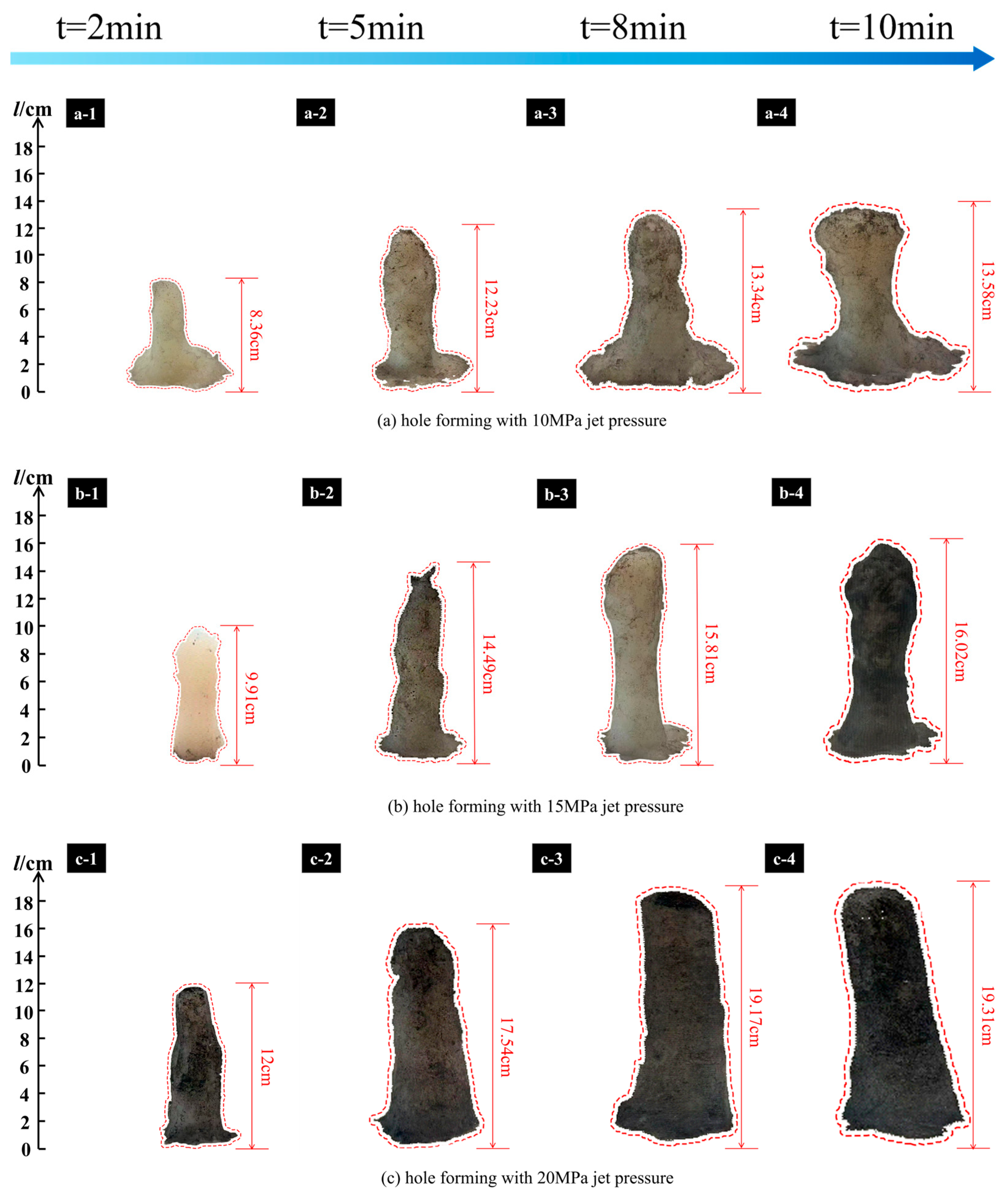
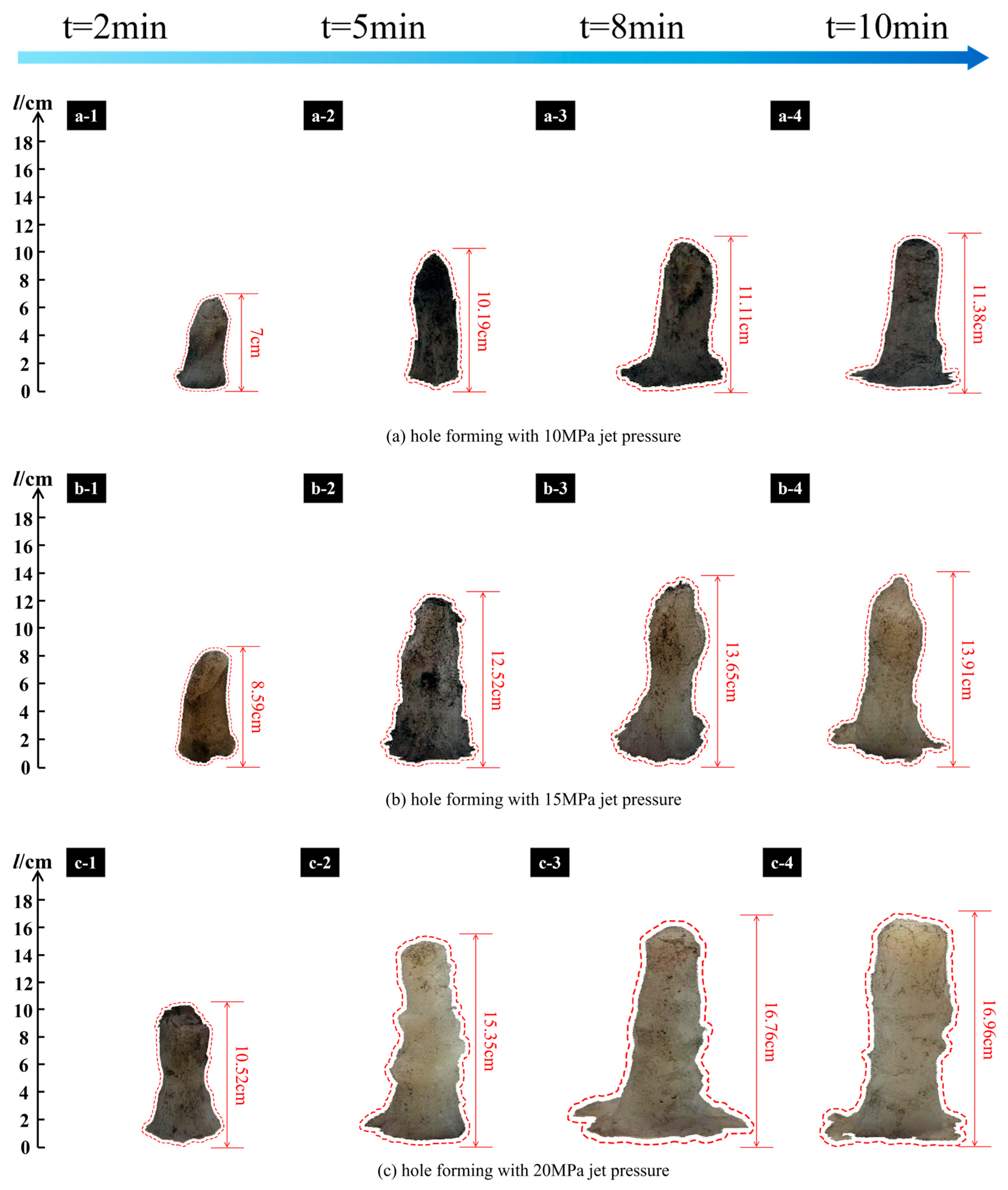
We precisely controlled the critical parameters of jet pressure, surrounding rock stress, and time, and observed and recorded the specific parameters of the complex hole morphology formed under the coupled effects of different confining pressures and jet pressure environments at 2, 5, 8, and 10 min. For Figure 5 and all subsequent analogous figures, the depth parameters of the holes in the silicone rubber mold were measured with a ruler accuracy of ±0.01 cm.
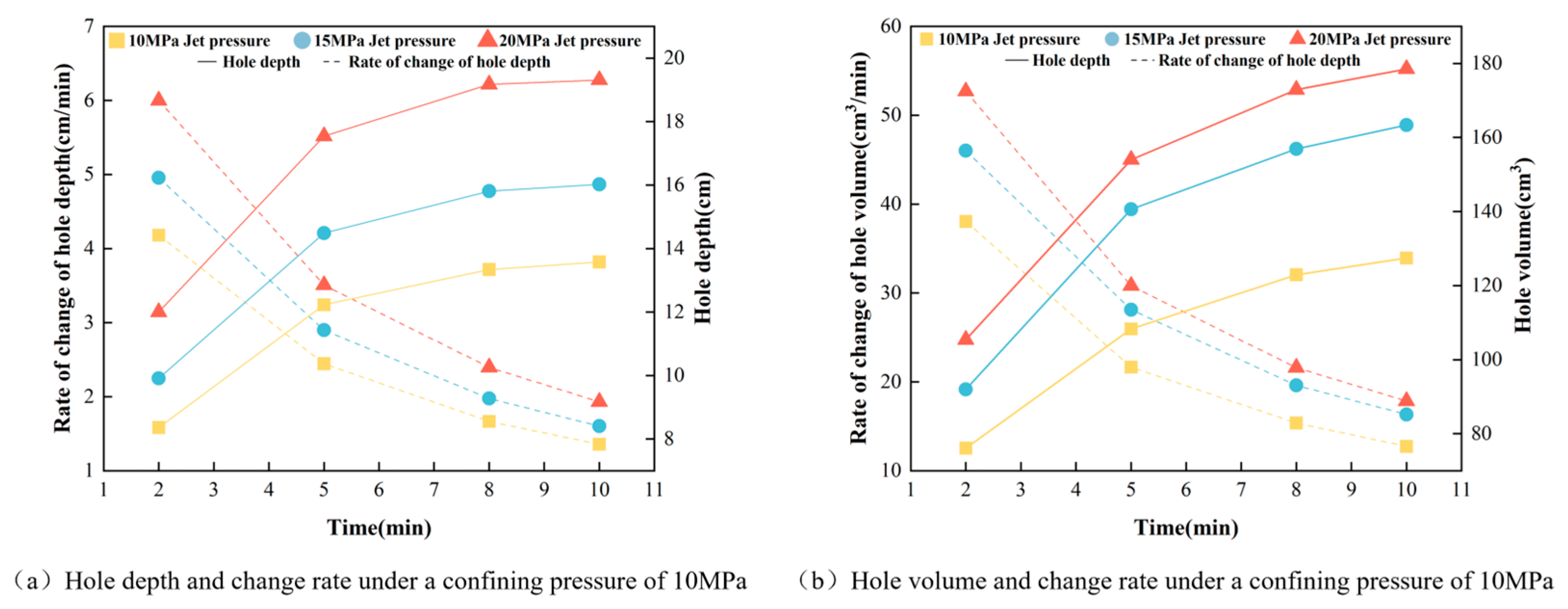
As shown in Figure 5 and Figure 6, when the jet pressure Pjp = 10 MPa impinges on the specimen for 2 min continuously, the cavity depth l and volume V account for 61.56% and 59.71% of the total results, respectively, with an average extension rate of 4.18 cm·min−1 for depth l and an average increase rate of 38.05 cm3·min−1 for volume V, indicating dramatic changes in the cavity’s geometric parameters. During the interval of 2 min ≤ t < 5 min, l and V accounted for 28.5% and 25.27% of the total results, respectively. The average extension and expansion rates of l and V were 1.29 cm·min−1 and 10.73 cm3·min−1, respectively. Although the rate of change in hole parameters slightly decreased compared to the previous time period, the geometric parameters of the holes still exhibited a trend of drastic changes, with rapid hole formation, resulting in an overall “wedge-shaped” morphology. During the interval of 5 min ≤ t < 8 min, l and V accounted for 8.17% and 11.48%, respectively; the average elongation rate of l and the average expansion rate of V were 0.37 cm·min−1 and 4.88 cm3·min−1, respectively. The variation rate of pore geometric parameters gradually decreased, and the pores maintained a “wedge-shaped” morphology. During the interval of 8 min ≤ t < 10 min, l and V accounted for 1.77% and 3.54%, respectively. The average extension and expansion rates of l and V were only 0.12 cm·min−1 and 2.26 cm3·min−1. Further weakening occurred in the variation in void geometric parameters, with void morphology transitioning toward “elliptical” or “teardrop-shaped” configurations.
When adjusting Pjp to 15 MPa and 20 MPa, the average extension rates of depth l were 1.60 cm·min−1 and 1.93 cm·min−1, respectively, representing increases of 17.97% and 42.19% compared to Pjp = 10 MPa; the average volume increase rates V were 16.33 cm3·min−1 and 17.85 cm3·min−1, respectively, showing improvements of 28.18% and 40.11% relative to Pjp = 10 MPa. Changing the jet pressure has a significant impact on the geometric parameters of hole formation, with a nonlinear positive correlation observed between jet pressure and variations in hole geometry. For 0 < t < 5 min, l accounted for 90.45% and 90.83% of the total results (Pjp = 15 MPa, 20 MPa); V accounted for 86.08% and 86.29% of the total results, respectively. When 5 min ≤ t < 10 min, l accounts for 9.55% and 9.17% of the total results, respectively (Pjp = 15 MPa, 20 MPa), and V accounts for 13.92% and 13.17% of the total results, respectively.
In summary, the dynamic evolution process of jet-induced hole formation in coal-rock masses exhibits significant stage-specific characteristics. The cavity evolution process can be categorized into a rapid expansion phase and a stable adjustment phase. Rapid Expansion Phase (0 < t < 5 min): l and V account for an average of 90.45% and 85.78% of the total results, respectively. The jet energy primarily manifests as longitudinal impact compressive stress. As it extends along the lengthwise direction, accumulated jet energy induces transverse tensile stresses. While the transverse damage zone of the hole expands, deepening predominantly occurs longitudinally, enabling rapid hole formation with a wedge-shaped profile. Stable Adjustment Phase (5 min ≤ t < 10 min): l and V account for an average of 9.55% and 14.04% of the total results, respectively. Fluid accumulates within the hole, significantly buffering the longitudinal impact compression force exerted on the coal-rock mass under submerged conditions by transforming jet energy into transverse dynamic pressure and shear effects. This causes lateral expansion of the hole, where its morphology gradually stabilizes as it transitions from a ‘wedge shape’ to an ‘elliptical’ or ‘teardrop’ form.
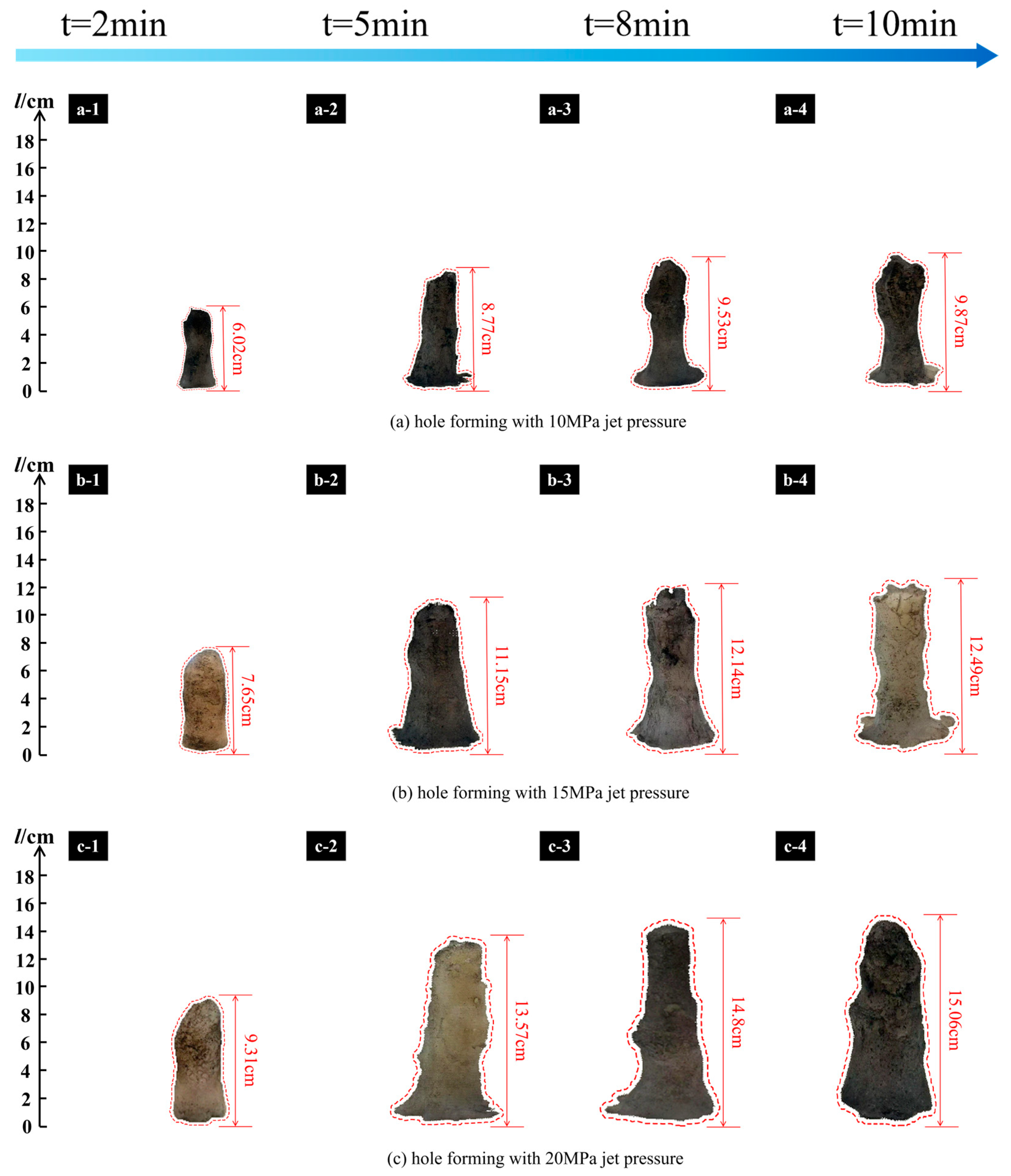
We changed the confining pressure parameter of the specimen Pcp = 20 MPa, while keeping other conditions including jet pressure and punching time constant. The variations in jet hole morphology and geometric parameters are illustrated in Figure 7, Figure 8 and Figure 9.
For 0 < t < 5 min, the average proportions of the holes’ depth l and volume V accounted for 90.02% and 88.66% of the total results, respectively; when 5 min ≤ t < 10 min, these values decreased to 9.98% and 11.34%. The variation in hole geometric parameters aligns with the stage-specific characteristics summarized in the preceding text. The overall geometric parameters of the voids significantly decreased compared to those at Pcp = 10 MPa; the average extension rate l reduced by 16.2%, 13.17%, and 12.17% under confining pressures of Pcp = 10 MPa, 15 MPa, and 20 MPa, respectively, while the average expansion rate V decreased by 18.05%, 24.13%, and 19.72%, correspondingly. An increase in confining pressure inhibits the development of hole morphology, resulting in a significant reduction in geometric parameters of the holes, exhibiting a negative correlation between them. The increase in confining pressure suppresses the transition of hole morphology towards an ‘elliptical’ or ‘teardrop-shaped’ form, while under sustained jet impact, the ‘wedge-shaped’ characteristics of the hole become more pronounced. Under the same jet pressure and time conditions, the morphology of duplicate silicone under different confining pressures in Figure 5(a-1–a-4) and Figure 7(a-1–a-4) all conforms to the above-mentioned variation characteristics.
The primary reasons for the aforementioned changes in hole characteristics are as follows: confining pressure suppresses the propagation of internal fractures within the coal seam, enhances the frictional effect inside the coal mass, and compresses pores to increase coal density. These effects significantly improve its overall strength, stiffness, load-bearing capacity, and erosion resistance [34].
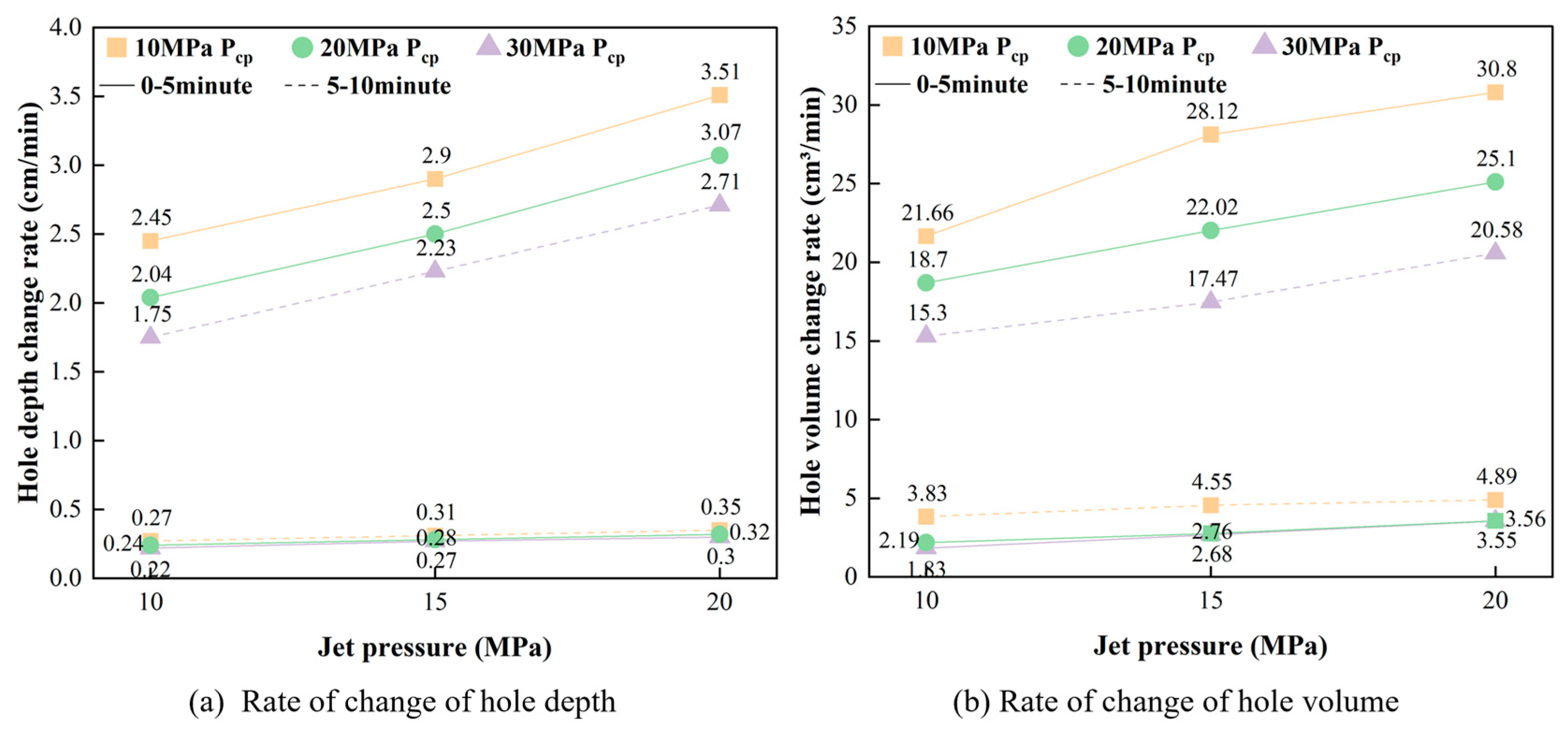
We increased the confining pressure of the specimen to Pcp = 30 MPa (with other experimental parameters held constant), and the changes in jet hole morphology and geometric parameters are presented in Figure 10, Figure 11 and Figure 12.
For 0 < t < 5 min, the average proportions of the hole depth l and volume V accounted for 89.41% and 87.09% of the total results, respectively, with the hole cave morphology remaining wedge-shaped. When 5 min ≤ t < 10 min, l and V contributed 10.59% and 12.91% on average to the total results. The increasing confining pressure enhanced its inhibitory effect on hole cave development, maintaining the initial wedge-shaped characteristics while geometric parameters continued to follow the previously summarized stage-specific patterns. Specifically, compared to Pjp = 10 MPa conditions, the extension rate of l decreased by 27.32%, 22.03%, and 22.01% under Pjp = 10 MPa, 15 MPa, and 20 MPa, respectively; correspondingly, the expansion rate of V reduced by 32.81%, 38.27%, and 32.38%. Higher confining pressure significantly suppressed jet-induced hole cave formation, leading to further reductions in geometric parameters.
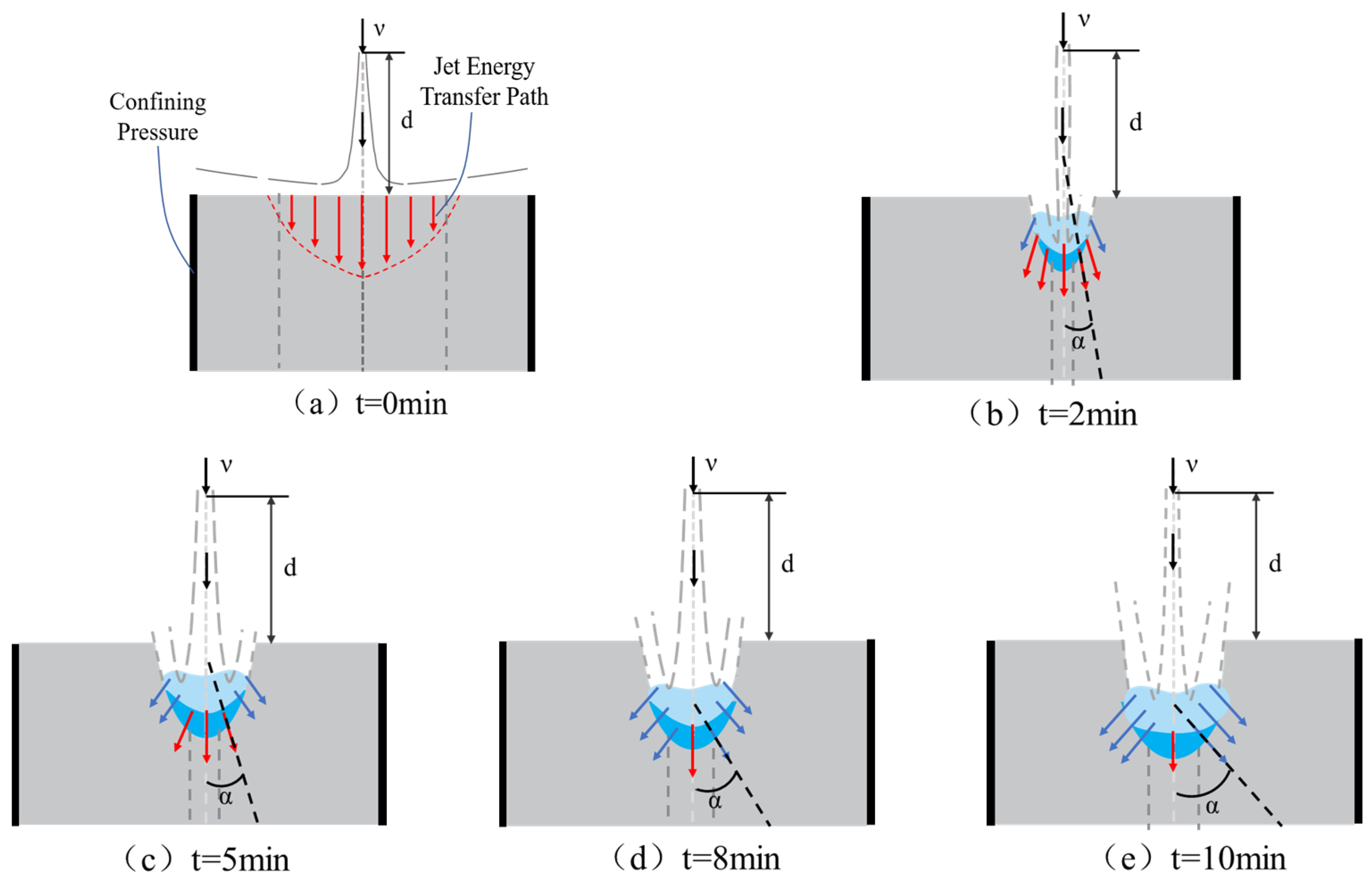
In summary, the dynamic evolution process of jet holes under the combined effects of jet pressure and confining pressure exhibits distinct stage-wise characteristics. During the rapid expansion phase (0 < t < 5 min), hole morphology development is dominated by longitudinal jet pressure. In the initial stage, the jet energy remains highly concentrated, with the water jet impacting the surface of coal-like material specimens vertically at velocity v. As continuous impingement occurs, the effective force angle α exhibits minimal variation during specimen surface interaction. The majority of the jet’s effective fracturing energy is efficiently transmitted along the longitudinal direction (Figure 13a,b). At this stage, depth l and volume V account for 89.96% and 87.17% of the total results, respectively, accompanied by dramatic changes in geometric parameters. Cavities extend rapidly toward depth while experiencing rapid volumetric expansion, forming wedge-shaped structures (consistent hole morphology evolution observed across all jet pressure conditions during 0 < t < 5 min in Figure 5, Figure 7 and Figure 10, e.g., a-1, a-2, b-1, b-2, c-1, c-2). During the stable adjustment period (5 min ≤ t < 10 min), under submerged conditions, the effective impact cannot act directly on the interior of the coal body along its initial direction. The energy transfer path of the jet shifts from being dominated by longitudinal penetration to transverse diffusion. In this stage, the variation range of the force angle α exerted by the water jet on the coal-like material is significant, and the effective energy for hole-breaking gradually transmits efficiently in the transverse direction (Figure 13c–e). At this time, l and V account for 10.04% and 12.82% of the total results, respectively. The rate of change in hole geometric parameters slows down, and the morphology evolves from a “wedge shape” to an “elliptical” or “teardrop shape” (under all jet pressure conditions, the hole morphology changes consistently during 5 min ≤ t < 10 min in Figure 5, Figure 7 and Figure 10, such as in a-3, a-4, b-3, b-4, c-3, c-4).
An increase in jet pressure leads to a more concentrated energy distribution within the jet, thereby enhancing its impact kinetic energy and coal-breaking efficiency while improving energy transfer efficacy. This results in significant alterations to both hole depth and volume, facilitating a morphological transition from the initial “wedge-shaped” configuration toward “elliptical” or “droplet-shaped” forms. When confining pressure increases, however, the incremental expansion of hole volume markedly diminishes. The elevated confining pressure strengthens the internal structural integrity and erosion resistance of the specimen, which impedes effective jet energy transmission. Consequently, the transformation of hole morphology into “elliptical” or “droplet-shaped” configurations becomes unattainable, causing the holes to retain their original “wedge-shaped” characteristics (as shown in c-4 of Figure 5, Figure 7 and Figure 10).

4. Conclusions

(1) The holes formed by jet impingement exhibit two distinct stages over time: a rapid expansion phase (0 < t < 5 min) and a stable adjustment phase (5 min ≤ t < 10 min). Rapid expansion stage: Under different confining pressures and jet pressure conditions, the average depth l and volume V account for 89.96% and 87.17% of the total results, respectively. Jet holes develop rapidly, with drastic changes in their geometric parameters, while the hole morphology consistently exhibits a ‘wedge-shaped’ form throughout its evolution. Stable shaping stage: The average proportions of l and V account for 10.04% and 12.82% of the total results, respectively. Void development tends to stabilize, with gradual slowing in changes to geometric parameters of voids. The morphology of voids transitions from an initial ‘wedge shape’ toward either an ‘elliptical’ or ‘teardrop’ form. However, when the confining pressure increases, it reinforces the internal structure and erosion resistance of the sample while weakening the efficiency of jet energy transfer. Consequently, the development of hole morphology struggles to achieve transition into an ‘elliptical’ or ‘teardrop-shaped’ form, ultimately retaining its original ‘wedge-shaped’ characteristics.
(2) The multi-field coupling effects of jet pressure, confining pressure, etc., influence the variation characteristics of jet hole formation. When confining pressure and time remain constant, an increase in jet pressure Pjp from 10 MPa to 20 MPa results in a 47.93% rise in average depth extension rate l and a 40.11% increase in average volume growth rate V. Specifically, higher jet pressure enhances jet energy, thereby significantly improving hole-forming efficiency. Conversely, confining pressure demonstrates an inverse relationship with variations in hole geometric parameters. When Pcp = 30 MPa, the average extension rate decreases by 23.79%, and the average dilation rate reduces by 34.5%. An increase in confining pressure enhances coal mass stability while suppressing the development of hole patterns formed by water jet impact.
(3) Based on silicone rubber replication technology, the system elucidates the dynamic evolution patterns of hole morphology under coupled jet pressure and confining pressure, clarifying its phased developmental characteristics and morphological transition mechanisms. By establishing mapping relationships between geometric parameters of cavities, jet parameters, and geostress environmental factors, optimized jet-confining pressure pathways are proposed for mines with distinct geological features. Dynamic adjustments of jet parameters can be implemented according to specific geological conditions such as coal seam burial depth, in situ stress states, and mechanical properties of coal bodies, thereby significantly enhancing both the application effectiveness and adaptability of high-pressure water jet technology in pressure relief and permeability enhancement for coal mines. The research findings provide a quantitative basis for optimizing jet parameters in coal seam gas control under diverse geological conditions, effectively supporting the enhanced application and engineering promotion of high-pressure water jet pressure relief and permeability improvement technology.

Author Contributions

Conceptualization, S.X.; methodology, S.X.; investigation, S.X., X.Z. (Xinrui Zhang) and X.Z. (Xu Zhou); data curation, H.Y., Y.X. and Z.H.; writing—original draft preparation, S.X. and X.Z. (Xinrui Zhang).; writing—review and editing, L.G. and J.Z.; visualization, X.Z. (Xu Zhou). and Y.Z.; supervision, L.G. and J.Z.; funding acquisition L.G. and J.Z. All authors have read and agreed to the published version of the manuscript.

Funding

This research was funded by the National Natural Science Foundation of China, grant number 52274202.

Data Availability Statement

The data used to support the findings of this study are included within this article.

Conflicts of Interest

The authors declare no conflicts of interest.

Nomenclature

HPWJHigh-Pressure Water Jet
HPAWJHigh-Pressure Abrasive Water Jet
FbuoyThe buoyancy force acting on the colloid
WThe weight of the colloid
WliquidThe weighed value of the colloid in the liquid
ρliquidThe density of the liquid
VliquidThe volume of displaced liquid
gThe local gravitational acceleration
VcolloidThe colloid volume
mliquidThe mass of the colloid
VholeThe hole volume
PjpThe jet pressure
lThe hole depth
VThe hole volume
tThe punching duration
PcpThe confining pressure
vThe water jet impact velocity
αThe force angle of water jet impact

References

  1. Yuan, L.; Zhang, T.; Wang, Y.; Wang, X.; Wang, Y.; Hao, X. Scientific problems and key technologies for safe and efficient mining of deep coal resources. J. China Coal Soc. 2025, 50, 1–12. [Google Scholar]
  2. Zhang, J.; Bai, X.; Song, Z.; Zhang, Y.; Dong, X.; Wu, S.; Xing, C.; Li, X.; Xu, W.; Zhang, S. Research Progress and Perspectives on Prevention and Control Technologies for Coal–Rock–Gas Composite Dynamic Disasters: New Types of Induced Classifications, Discriminant Criteria, and Structural Control Schemes. Rock Mech. Rock Eng. 2025, 58, 10143–10181. [Google Scholar] [CrossRef]
  3. Xu, F.; Hou, W.; Xiong, X.; Xu, B.; Wu, P.; Wang, H.; Feng, K.; Yun, J.; Li, S.; Zhang, L.; et al. The status and development strategy of coalbed methane industry in China. Pet. Explor. Dev. 2023, 50, 765–783. [Google Scholar] [CrossRef]
  4. Niu, X.; Zhao, Y.; Li, K.; Zhang, Y.; Abu-Jdayil, B. Ultra-High-Pressure Hydraulic Slitting Pressure Relief and Penetration Enhancement Technology and Equipment for Soft Coal Seams. Geofluids 2022, 2022, 1895836. [Google Scholar] [CrossRef]
  5. Cao, S.; Ge, Z.; Zhang, D.; Zhou, Z.; Lu, Y.; Zhao, H. An experimental study of ultra-high pressure water jet-induced fracture mechanisms and pore size evolution in reservoir rocks. Int. J. Rock Mech. Min. Sci. 2022, 150, 104995. [Google Scholar] [CrossRef]
  6. Yiyu, L.U.; Shan, H.; Zhaolong, G.E.; Zhe, Z.H.O.U.; Wenchuan, L.I.U.; Yarui, G.U.A.N. Research progress and strategic thinking of coal mine water jet technology to enhance coal permeability in China. J. China Coal Soc. 2022, 47, 3189–3211. [Google Scholar]
  7. Tomassi, A.; de Franco, R.; Trippetta, F. High-resolution synthetic seismic modelling: Elucidating facies heterogeneity in carbonate ramp systems. Pet. Geosci. 2025, 31, petgeo2024–petgeo2047. [Google Scholar] [CrossRef]
  8. Ge, Z.; Zhang, H.; Zhou, Z.; Cao, S.; Zhang, D.; Liu, X.; Tian, C. Experimental study on the characteristics and mechanism of high-pressure water jet fracturing in high-temperature hard rocks. Energy 2023, 270, 126848. [Google Scholar] [CrossRef]
  9. Sun, H.; Yang, H.; Guo, H.; Ma, S. Study on the Effect of Hydraulic Flushing on the Stress and Permeability Variations of Loaded Coal. ACS Omega 2025, 10, 8292–8302. [Google Scholar] [CrossRef] [PubMed]
  10. Ge, Z.; Cao, S.; Lu, Y.; Gao, F. Fracture mechanism and damage characteristics of coal subjected to a water jet under different triaxial stress conditions. J. Pet. Sci. Eng. 2022, 208, 109157. [Google Scholar] [CrossRef]
  11. Shang, Y.; Wang, Y.; Zhang, L.; Wu, G.; Kong, D.; Zhang, P.; Jia, T. Impact of lower protective coal seam mining on overlying strata: Deformation, pressure relief, and permeability enhancement. Int. J. Geomech. 2024, 24, 04024178. [Google Scholar] [CrossRef]
  12. Ge, Z.L.; Zhao, H.Y.; Lu, Y.Y.; Xiao, S.Q.; Zhou, Z.; Bo, T. Damage and fracture characteristics of coal sandstone shale under high pressure water jet impact. J. Vib. Shock. 2021, 40, 174–181. [Google Scholar]
  13. Lei, Z.; Yan, P.U.; Yu, P.; Binwei, X.; Liulin, F. Mechanism and influencing factors of rock breaking and pore-forming by water jet in deep coal seam based on the MPM. J. China Coal Soc. 2024, 49, 3845–3858. [Google Scholar]
  14. Xiao, S.; Xiao, J.; Ren, Q.; Cheng, Y.; Li, W.; Zhang, W.; Meng, X.; Qin, H. Damage evolution and fracture characteristics of heterogeneous concrete with coarse aggregate impacted by high-velocity water jet. Constr. Build. Mater. 2024, 416, 135128. [Google Scholar] [CrossRef]
  15. Xiao, S.; Qin, H.; Zhang, W.; Ren, Q.; Xiao, J.; Li, W.; Cheng, Y. On the concrete breakage by pulsed water jet impact: Fracture characteristic, stress and damage evolution laws. Case Stud. Constr. Mater. 2023, 19, e02634. [Google Scholar] [CrossRef]
  16. Xue, Y.; Si, H.; Chen, G. The fragmentation mechanism of coal impacted by water jets and abrasive jets. Powder Technol. 2020, 361, 849–859. [Google Scholar] [CrossRef]
  17. Zhang, X.; Wiśniewski, P.; Dykas, S.; Zhang, G. Permeability enhancement properties of high-pressure abrasive water jet flushing and its application in a soft coal seam. Front. Energy Res. 2021, 9, 679623. [Google Scholar] [CrossRef]
  18. Zhou, X.; Gao, M.; Liu, J.; Yang, L.; Hao, H.; Yang, B.; He, Z.; Wang, X. Mechanism and Feasibility Evaluation of Laser-Assisted Rock-Breaking in Drilling Fluid Environment. Rock Mech. Rock Eng. 2025, 1–22. [Google Scholar] [CrossRef]
  19. Peel, B.; Lee, W.; Hussein, N.; Yoo, S.-J. State-of-the-art silicone molded models for simulation of arterial switch operation: Innovation with parting-and-assembly strategy. JTCVS Tech. 2022, 12, 132–142. [Google Scholar] [CrossRef]
  20. Bell, M.A.; Becker, K.P.; Wood, R.J. Injection molding of soft robots. Adv. Mater. Technol. 2022, 7, 2100605. [Google Scholar] [CrossRef]
  21. Wang, D.; Liu, Z. Study and application of evaluation method for fracability of deep CBM reservoir-taking the Daning-Jixian block in the Ordos Basin as an example. Int. J. Oil Gas Coal Technol. 2024, 35, 407–441. [Google Scholar] [CrossRef]
  22. Wen, H.; Fan, C.; Jiang, X.; Luo, M.; Xiao, B.; Zhou, L.; Yang, Z. Experimental investigations on enhanced coal seam methane extraction by injecting gas: A review. Energy Fuels 2024, 38, 3517–3538. [Google Scholar] [CrossRef]
  23. Wang, H.; Yang, S.; Zhang, L.; Xiao, Y.; Su, X.; Yu, W.; Zhou, D. Experimental analysis of the mechanical properties and failure behavior of deep coalbed methane reservoir rocks. Processes 2024, 12, 1125. [Google Scholar] [CrossRef]
  24. Cao, S.; Wang, X.; Ge, Z.; Guo, Z.; Zhang, L. Experimental study on the damage and fracture mechanism of deep coal beds impacted by water jets at different temperatures. Fuel 2024, 371, 132121. [Google Scholar] [CrossRef]
  25. Li, H.; Xu, P.; Zhang, L.; Jiang, H.; Chen, Y.; Sun, D. Numerical and experimental investigation on rock breaking mechanism and performance of high-pressure energy-gathering water jet. Eng. Fract. Mech. 2025, 320, 111050. [Google Scholar] [CrossRef]
  26. Lei, Y.; Cheng, Y.; Wang, L.; Ren, T.; Tu, Q. Mechanisms of coal and gas outburst experiments: Implications for the energy principle of natural outbursts. Rock Mech. Rock Eng. 2023, 56, 363–377. [Google Scholar] [CrossRef]
  27. Qiao, G.; Liu, Z.; Zhang, Y.; Yi, C.; Gao, K.; Fu, S.; Zhao, Y. Theoretical analysis and engineering application of controllable shock wave technology for enhancing coalbed methane in soft and low-permeability coal seams. Int. J. Coal Sci. Technol. 2024, 11, 25. [Google Scholar] [CrossRef]
  28. Li, J.-Q.; Wang, Z.-F.; Wang, Y.-Q.; Chang, H.-T. Analysis and countermeasures of large deformation of deep-buried tunnel excavated in layered rock strata: A case study. Eng. Fail. Anal. 2023, 146, 107057. [Google Scholar] [CrossRef]
  29. Wu, D.; Luo, C.; Gao, Z.; Li, D.; Xu, C. Effect of different reinforced load transfer platforms on geosynthetic-reinforced pile-supported embankment: Centrifuge model test. KSCE J. Civ. Eng. 2022, 26, 630–649. [Google Scholar] [CrossRef]
  30. Wan, F.; Jiang, Z.; Tian, X.; Konietzky, H.; Xiao, Z. A thermo-hydro-mechanical damage model for lined rock cavern for compressed air energy storage. J. Energy Storage 2024, 78, 110186. [Google Scholar] [CrossRef]
  31. Yuan, M.; Liu, Y.; Niu, Y.; Yang, T.; Yu, B.; Yin, L.; Wen, X.; Long, Z.; Jiang, M. Crushing mechanism and influencing factors of gas-containing coal under water jet impact loading. Powder Technol. 2025, 465, 121350. [Google Scholar] [CrossRef]
  32. Jiang, M.; Sun, B.; Niu, Y.; Liu, Y.; Long, Z.; Bu, X. Insights and simulation models for long-distance water jet mining: Evolution of breaking depth and mass. Process Saf. Environ. Prot. 2025, 195, 106761. [Google Scholar] [CrossRef]
  33. Narushin, V.G.; Volkova, N.A.; Vetokh, A.N.; Dzhagaev, A.Y.; Sotnikov, D.A.; Volkova, L.A.; Orszulik, S.T.; Griffin, D.K.; Romanov, M.N.; Zinovieva, N.A. Reimagining Archimedes: An innovative and accurate calculation of volumes and asserting another standard method for defining the surface area of quail and any avian eggs. Food Bioprod. Process. 2024, 147, 327–334. [Google Scholar] [CrossRef]
  34. Liu, W.; Hu, Z.; Liu, C.; Huang, X.; Hou, J. Mechanical properties under triaxial compression of coal gangue-fly ash cemented backfill after cured at different temperatures. Constr. Build. Mater. 2024, 411, 134268. [Google Scholar] [CrossRef]
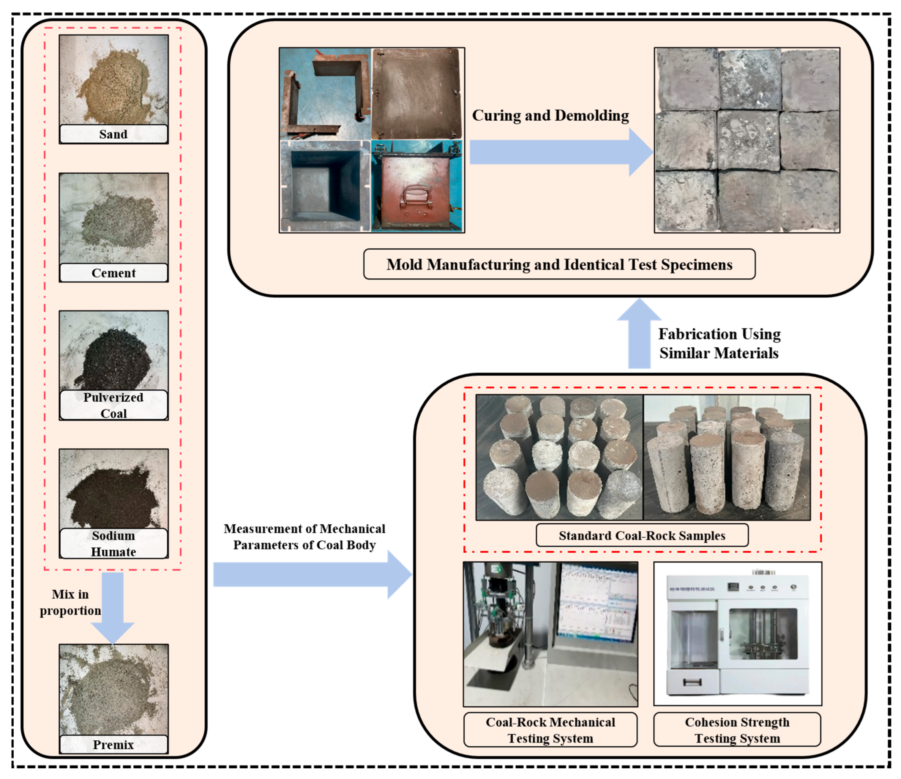
Figure 1. Production process for water jet punching of similar material test specimens.
Applsci 15 10132 g001
Figure 2. High-pressure water jet punching device and novel integrated surrounding rock stress simulation system.
Applsci 15 10132 g002
Figure 3. Schematic diagram of the production process for silicone rubber duplicate mold colloids.
Applsci 15 10132 g003
Figure 4. Schematic diagram of silicone replication experiment process.
Applsci 15 10132 g004
Figure 5. Morphology of voids under confining pressure of 10 MPa.
Applsci 15 10132 g005
Figure 6. Geometric parameters and rate of hole-forming for the specimen under a confining pressure of 10 MPa.
Applsci 15 10132 g006
Figure 7. Cavity complex modulus morphology under confining pressure of 20 MPa.
Applsci 15 10132 g007
Figure 8. Geometric parameters of specimen hole formation under confining pressure of 20 MPa.
Applsci 15 10132 g008
Figure 9. Hole depth and volumetric change rate of specimens at various stages under confining pressures of 10 MPa and 20 MPa.
Applsci 15 10132 g009
Figure 10. Hole complex modulus morphology under confining pressure of 30 MPa.
Applsci 15 10132 g010
Figure 11. Geometric parameters of specimen holes under confining pressure of 30 MPa.
Applsci 15 10132 g011
Figure 12. Hole depth and volumetric strain rate of specimens at various stages under confining pressures of 10 MPa, 20 MPa, and 30 MPa.
Applsci 15 10132 g012
Figure 13. Schematic diagram of dynamic evolution process of jet holes. (a,b) Rapid Expansion Phase (0 < t < 5 min). (ce) Stable Adjustment Phase (5 min ≤ t < 10 min).
Applsci 15 10132 g013
Table 1. Mechanical property parameters of deep coal seams.
Representative Coal SeamCompressive Strength (MPa)Elastic Modulus (MPa)Cohesion (MPa)Poisson’s Ratio
Deep Coal Seam 1#23.24.965.920.34
Deep Coal Seam 2#24.1553.20.32
Deep Coal Seam 3#23.734.513.40.39
Average23.6934.8234.170.343
Table 2. Mixture proportioning plans for specimens of similar materials and determination results of mechanical property parameters.
Serial NumberCementCoal PowderSandSodium HumateCompressive Strength (MPa)Elastic Modulus (MPa)Cohesion (MPa)Poisson’s Ratio
130.00%50.00%18.50%1.50%2.394.880.420.34
230.00%40.00%28.10%1.90%2.564.930.290.2
340.00%40.00%17.70%2.30%4.375.210.320.25
440.00%30.00%28.20%1.80%3.035.070.710.45
550.00%30.00%17.50%2.50%3.295.160.350.28
Table 3. Main equipment parameters of high-pressure water jet experimental platform.
NameSpecificationBasic Parameters
Water TankDimensions (m)2.5 × 2.5 × 1.5
Electric MotorPower (kW)160
High-Pressure Steel PipeLength (m)10
Inner Diameter (cm)8
Outer Diameter (cm)10
High-Pressure Water PumpFlow Rate (m3·h−1)180–240
JetPressure (MPa)10–30
Hydraulic Control ModulePressure (MPa)0–40
Table 4. Value assignment of key parameters for jet perforation experiment.
ParameterValue
Jet Pressure (MPa)10, 15, 20
Confining Pressure Conditions (MPa)10, 20, 30
Perforation Duration (min)2, 5, 8, 10
Nozzle Diameter (mm)8
Target Distance (m)1.2, 1.5, 1.8
Similar Material Specimen Dimensions (mm)250 × 250 × 250
Disclaimer/Publisher’s Note: The statements, opinions and data contained in all publications are solely those of the individual author(s) and contributor(s) and not of MDPI and/or the editor(s). MDPI and/or the editor(s) disclaim responsibility for any injury to people or property resulting from any ideas, methods, instructions or products referred to in the content.