Article

Analysis of the Application of Analytical and Numerical Methods for the Dimensioning of Pin Connections of Folding Bridges

Faculty of Civil Engineering and Geodesy, Military University of Technology, ul. gen. Sylwestra Kaliskiego 2, 00-908 Warsaw, Poland
*
Author to whom correspondence should be addressed.
Appl. Sci. 2025, 15(18), 10047; https://doi.org/10.3390/app151810047
Submission received: 16 July 2025 / Revised: 5 September 2025 / Accepted: 11 September 2025 / Published: 14 September 2025
(This article belongs to the Section Civil Engineering)

Abstract

This paper presents a static-strength analysis of the construction of folding bridges, addressing in particular the dimensioning of pin connections. These connections are elements that transfer the axial forces between the chords of truss girders of connected span sections. First, the various components of folding bridges and the materials from which they are made are characterised. The characteristics of pin connections in modern folding bridge structures are discussed, including their influence on the static scheme of the entire structure. The parameters of such pin connections are presented in terms of both the strength of such a connection and cooperation of its components. The main part of this article is a detailed design analysis of the pin connection of the new MSC 23-150 “Cis” folding bridge structure, the concept of which was developed at the Faculty of Civil Engineering and Geodesy of the Military University of Technology. The calculations were carried out both analytically and with a spatial numerical model, which allowed us to determine the stresses on the connection components in the critical sections and propose the final shape of the connector. This article presents the effect of combining known methods of dimensioning pin connections and a method related to determining actual stress values by taking into account the so-called stress concentration factor in analytical calculations. Taking into account the real area of impact of the pin on the bridge pin joint element affects the stress concentration, which can cause an increase in stress in selected cases by up to 300%. Original results are presented on the relationship between individual stress values in specific cross-sections of the connection and the values of assembly clearances in prefabricated bridge structures, as well as their mutual relationships for specific values of assembly clearances. The above information is important when developing and operating bridges made of portable truss-type bridge structures. Knowledge of the phenomenon of stress concentration reduction when limiting assembly clearance allows for the safe and effective use and construction of this type of bridge structure.

1. Introduction

Folding bridge structures are engineered structures that allow the construction of crossings from pre-manufactured, identical components [1,2]. In many cases, the versatility of the components enables the construction of crossings with a wide range of performance characteristics by using different span structure arrangements in addition to different support spacings. Due to the high variability of the solutions and the short construction time of the crossing, folding bridge structures have multiple applications in transport construction. These structures enable the construction of communication routes to support local residents even during the most unusual emergency situations [3] and include construction of crossings during repairs of permanent bridges [4,5], adaptation to the role of permanent crossings [6] and restoration of crossings in emergency situations such as natural disasters [7,8].
Foreign designs of folding bridges used in Poland and around the world are mainly the British Mabey Compact 200 and Mabey Logistic Support Bridge and the American Acrow 700XS [9,10]. MS-22-80, MS-54 and DMS-65 are currently available and used modern folding structures in Poland. These structures were designed in the middle of the last century, for the loads and vehicles used by the Armed Forces at the time [2,11].
Nowadays, due to increased dimensions and loads from increased design loads for civilian rolling stock, the domestic folding bridge structures do not meet the requirements of modern transport construction. The main parameters that are not achieved by the current domestic folding bridge designs include the required crossing capacity, as well as the lane width required to create a crossing with the specified characteristics [11]. The spans obtainable for the required load-bearing classes would require the construction of a large number of intermediate supports. To illustrate the problem, it is worth noting that, due to the width of the bridge deck, the basic design of the DMS-65 bridge prevents the construction of a two-way crossing while maintaining reasonable span lengths. Two-way traffic on this bridge requires a system of three girders with two lanes (Figure 1).
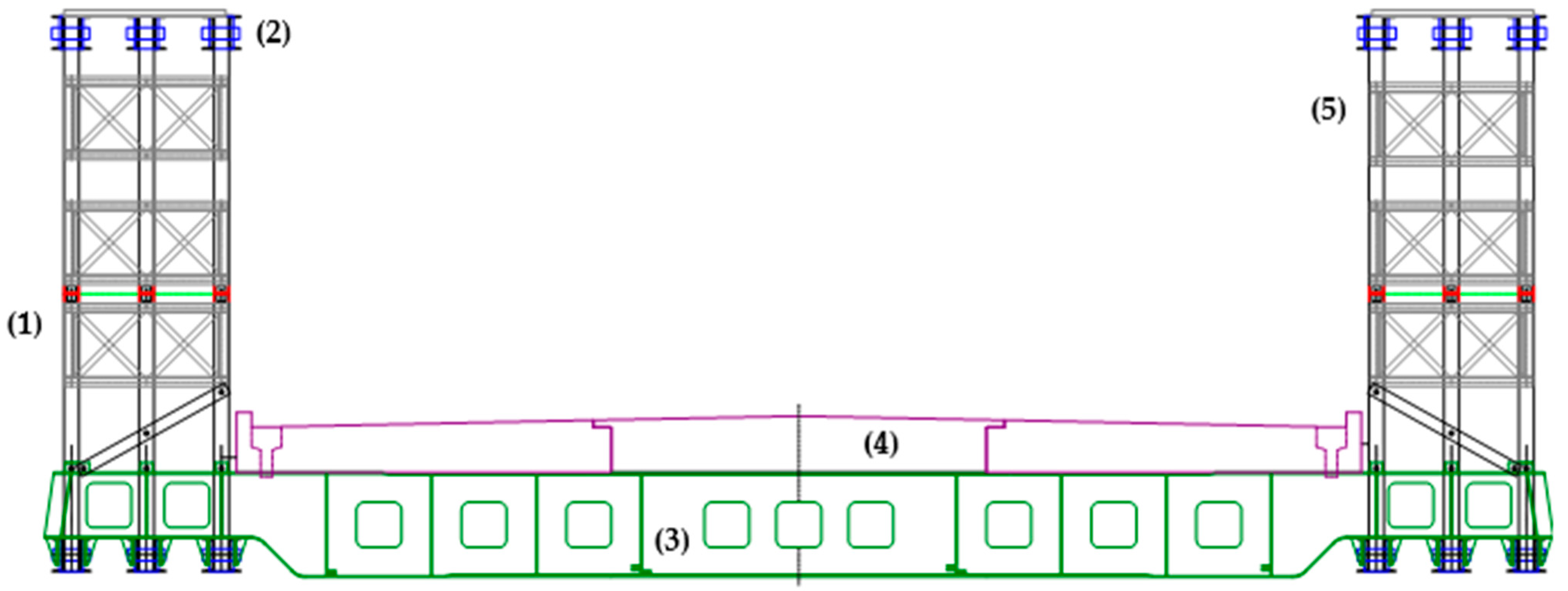
In view of the problems described above and the global trend towards improving the design of folding bridges [12], the WAT Institute of Civil Engineering and Geodesy proposed a concept for a new MSC 23-150 “Cis” road folding bridge (Figure 2). This structure is intended to allow the passage of heavy equipment and provide adequate capacity for logistics transport columns in compliance with the requirements of the standards and agreements in force [11,13]. For the construction of crossings with the performance required today [14,15], a number of solutions have been proposed in the MSC 23-150 construction concept, including the following:
-
The amount of steel required in the girders was reduced, e.g., by removing the sections from the neutral axis of the girder cross-section in the storied arrangement [16]. The construction solution used was noted as an invention (number P.438762).
-
An innovative solution for the cross-beam was used, and a plate and grating system was designed; this allowed a significant reduction in the weight of this element. The construction solution used was claimed as an invention (number P.448192).
-
The number of elements in the structure has been reduced while ensuring the possibility of constructing a number of variants of the structural system; this will allow the crossing to be easily adapted to local conditions and the needs of the users.
-
Modern composite materials, which are widely applied in civil engineering, were used to make deck slabs [17,18,19,20,21,22]; the slabs were shaped with pre-set gradients and a built-in drainage system, which ensures that rainwater is drained from the deck surface in accordance with modern environmental requirements.
When designing and operating bridges, including MSC 23-150, the method of connecting bridge sections is a very important issue. The most effective solution is a pin connection, which ensures quick assembly of the bridge. Unfortunately, due to the efficiency of assembly, so-called assembly clearances are made—pins with a diameter smaller than the hole in the connector elements are used. The selection of these parameters is extremely important for the stress distribution in the pin connection of folding bridges, where the forces transmitted by these connections are significant. This article presents a proposed method for taking assembly clearance into account when determining the stress values in individual cross-sections of this type of connection.

2. Influence of Pin Connection Assembly Clearances on the Distribution of Internal Forces in Folding Bridges

A key feature of folding bridges, from the point of view of their structural performance, is the use of pin connections as the main connections between bridge segments. It is worth noting that these connections, due to the assembly clearance required for smooth and quick assembly of the folding bridge segments, have a significant impact on the performance of the entire structure, determining the disturbance of the standard load–displacement relationship [1,2].
In the analysis of folding bridge structures, there are some theoretical issues related to the specific characteristics of folding structures caused by assembly clearances. One of these is the reduced stiffness of the structure, which results in reduced support moments and increased span moments in relation to a free-supported continuous beam—Figure 3.
Another issue is the performance characteristics of the connector itself. In addition, there is a different effect of dynamic loads acting on a folding structure compared to those on a fixed (monolithic) structure. These clearances allow limited rotation of adjacent bridge members relative to each other in two planes. This causes the structure to deflect into a concave curve, resulting in an increase in the deflection arrow of the structure and a centrifugal force that further stresses the structure. The increase in internal forces from this phenomenon is relatively small; for typical rolling stock speeds on a folding bridge, it is about 0.6% compared to the internal forces of fixed structures, where there is no phenomenon of assembly clearance.
A more serious problem is the potential buckling of the structure in the horizontal plane. A buckling order of 10 mm significantly increases the forces in the top chords, where their stability can be a decisive factor in the load-bearing capacity of the structure. The drop in load-bearing capacity of structures with a span of more than 30 m can be more than 30%.
In practice, static-strength calculations taking into account the effect of assembly clearances of pin connections should be preceded by the determination of the following key parameters [2]:
-
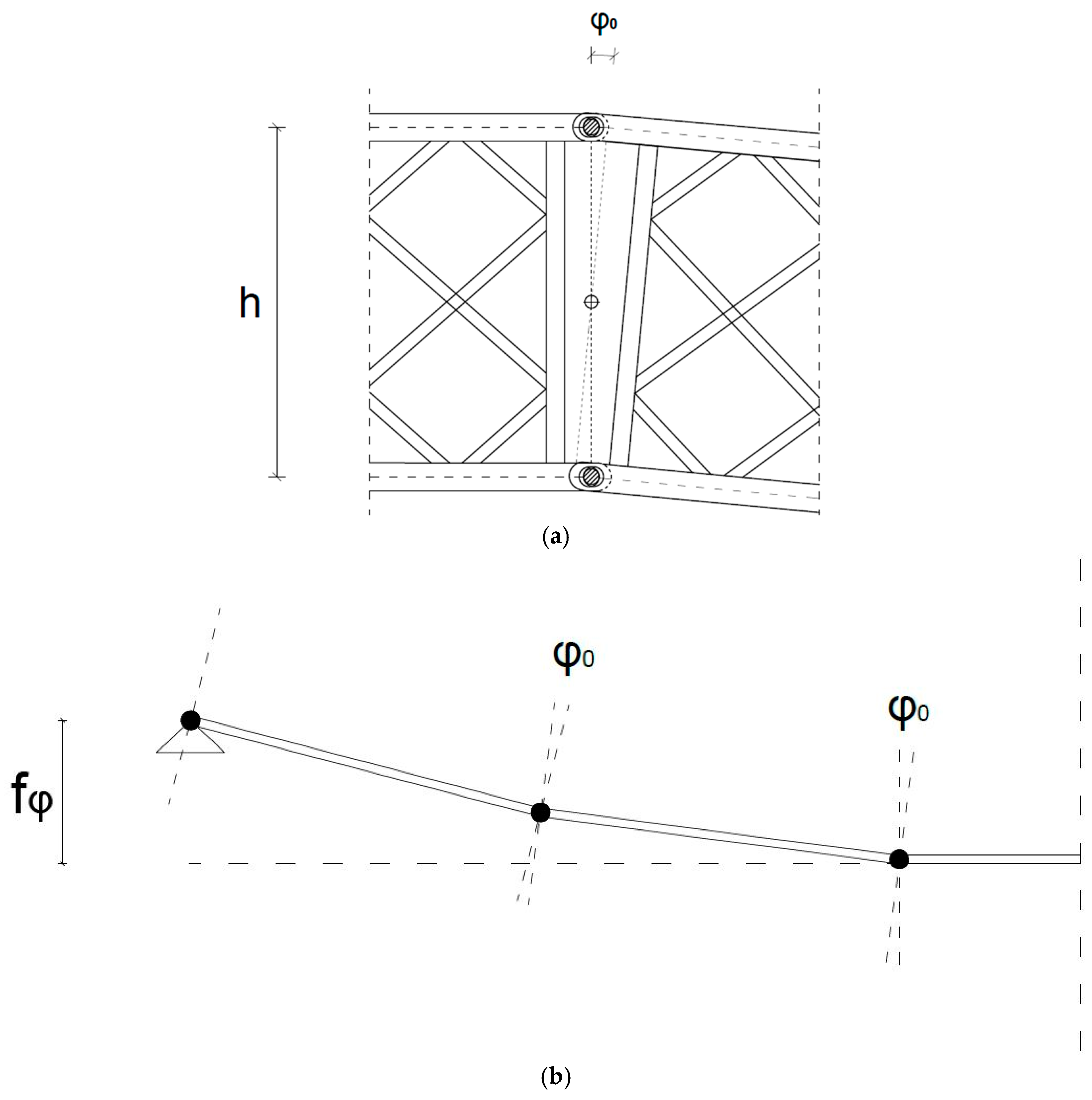
The folding angle between the bridge segments (Figure 4);
-
The radius of the kinematically deformed structure;
-
Deflection of the kinematically deformed structure (Figure 4);
-
Angle of rotation of the support section from the assembly clearances.
In the context of deflections, another phenomenon to bear in mind is the kinematic deflection of the structure caused by pin clearance and the possibility of trusses rotating relative to each other.
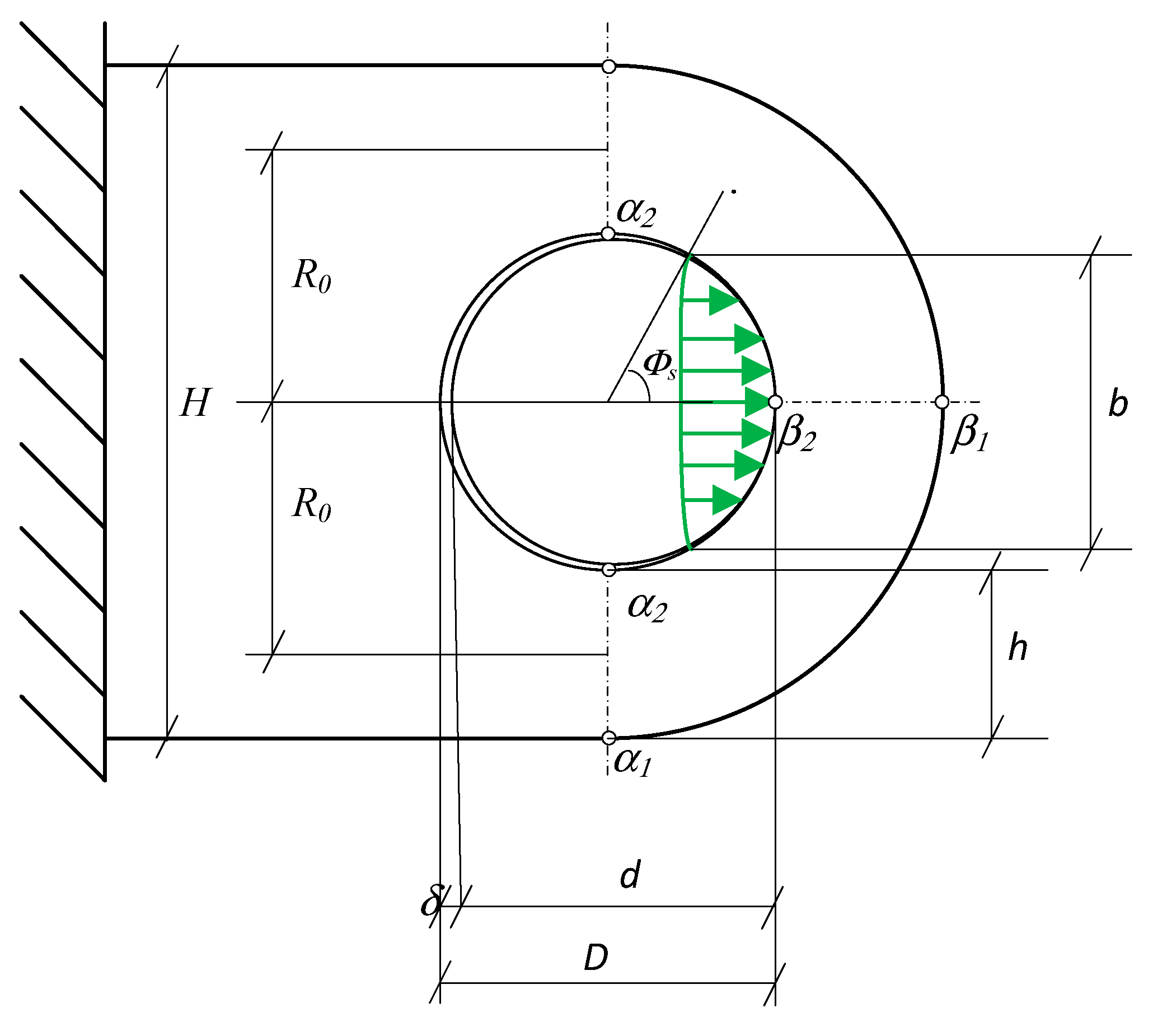
In the connection under load, there are elastic deformations causing a change of shape from circular to elliptical in a flat deformation fitting the pin to the eye of the connection which, in view of existing assembly clearances, produces the external pressure area at the pin/eye connection interface; the connection geometry is shown in the figure below—Figure 5.
The legend is as follows:
H—height of the pin connection;
D—pin hole diameter;
d—pin diameter;
δ—assembly clearance, with δ = D − d;
Ro—distance from the centre of the pin hole to halfway up the pin eye;
h—height of the pin eye;
b—height of the contact area.
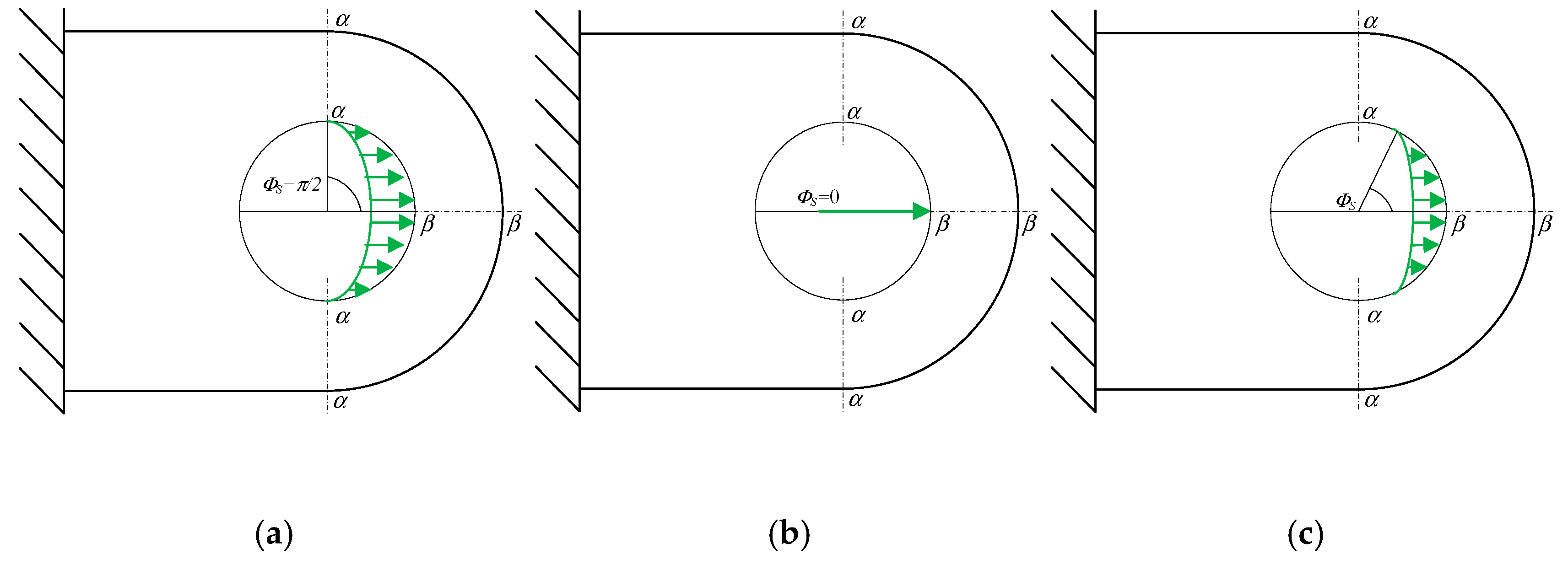
Due to the way in which the load is transferred in the pin connection itself in the eye/pin layout, we distinguish between three ways of loading the force P in the connection [23].
-
Load on the “full” contact area, with the connection clearance assumed to be zero—Figure 6a;
-
Concentrated force load, i.e., assuming point contact between the pin and the connection—Figure 6b;
-
Load with a “limited” contact area—Figure 6c.
Due to the deformations occurring under load in the connection, the deformation of the eye and pin is most closely related to the actual working conditions of the pin connection. The height b of the contact area acting on the connection as a function of the force load P can be determined using the Hertz formula ([23], based on [24,25]):
b = 1.76 P E · D · d δ 3 ,
where E—the Young’s modulus of the pin connection steel.
s i n Φ s = b D ,
and hence, the angle of half the pressure contact area is
Φ s = arcsin b D ,
The analytical method presented above makes it possible to calculate pin connections provided that the longitudinal cross-section remains constant, but it is difficult to use it for the dimensioning of existing connections or the design of new connections. This is due to the fact that their sections are variable in cross-section, as a result of the need to shape them geometrically to match the bridge chord structure.
Ref. [26] presents a set of equations defining the stress state and behaviour of pin connections based on available research in the literature, although they only apply to connections for a certain range of their geometry. The authors of study [27] report that there is an approximately linear reduction in the load-carrying capacity of the connection with potential connection failure variants due to an increase in the tolerance of the pin/hole dimensions. This assumption may be valid for a small change in the amount of clearance δ in the connection. For the full range of load application variations, from a concentrated force to a full external contact area, the values of the stress concentration coefficients in the sections change in a non-linear fashion [28]. The connection failure mechanisms are presented, among others, in article [29], which essentially presents an analysis of pin fatigue. Based on the results of the study, amendments to Eurocode [30] have been proposed, including the possibility to design the pin as a shear bolt and principles for verifying the load-bearing capacity of the pin itself.
In works [31,32], it is possible to find the results of experimental tests and the spatial numerical models of pin connections developed on their basis. The connections tested were quite thin, while in the case of folding bridges, pin connections are very stiff in tension, compression and shear. In addition, it should be noted that the range of displacement at the connection pin–eye interface is small, due to the folding angle between the bridge segments (cf. Figure 4). The analytical methods presented above were used for the initial dimension verification of the pin connection, while accurate static-strength calculations of the connection could be made using numerical models of the connection performance. In order to define a model for numerical studies, Section 3 proposes an example of a pin connection that meets the requirements related to the characteristics of the MSC 23-15 bridge and its capabilities.

3. Bridge Pin Connection Concept MSC 23-150

The pin connection of folding bridge structures consists of three main parts: a single bracket (eye), a double bracket (eye) and the pin between them. When the load is transferred through the folding structure, the pins in the connection are subjected to a rotational movement around their axis. They should therefore be accurately machined and have a smoothed surface to minimise friction between the pin and the bracket (eye). It is assumed that the steel of which the pin connections and the pin itself are made should have a compressive strength one grade higher than that of the steel of the girders of folding bridges. It is also important to remember to protect the pins against corrosion, e.g., by galvanising [1]. The proposed connector for the MSC 23-150 folding bridge structure is shown in the figure below (Figure 7). The geometrical parameters of the connection are determined by structural, functional or installation considerations; e.g., the height of the connection is the same as the height of the chords of the bridge girders. This connection will ensure the transfer of load from the MSC 23-150 bridge girders. It is adopted for the purpose of analysing the impact of assembly clearance on the operation of the connection (stress distribution in the connection). For the joint to work, taking into account the assembly clearance, it is important to optimise the entire joint, not just the pin. This is due to the practical aspect of building structures from prefabricated bridges. Assembly clearance is necessary for the easy and quick connection of bridge sections—the greater the clearance, the easier the assembly of the pin. On the other hand, too large a pin diameter increases the weight of this element, making it difficult to assemble in joints.
The pin connection, due to the way it works, should be verified considering the following aspects [1]:
-
Pin shear;
-
The pressure of the pin on the brackets or the mutual compression of the pin and the brackets;
-
Stretching of the net section of a single bracket or stretching of a single bracket;
-
Pin bending.
The analysis is based on the assumption of static load and the elastic range of the structure. This is due to the operating conditions of folding bridges, which are used at low vehicle speeds and very often when very heavy vehicles are moving, which are the only ones on the folding bridge during their passage. Such operating conditions imply an analysis based on static load assumptions. However, the potential use of folding bridge structures as a final crossing also necessitates analysis based on dynamic loads. Certainly, the dynamic loads resulting from high-speed vehicle traffic increase the impact on bridge elements in relation to static loads. However, due to the negligible use of this type of structure as a bridge for continuous operation, the focus was on static analysis. However, analysis only in the elastic range refers to the limit values within which a composite bridge element can be operated. If a structural element enters the plastic range, it cannot be reassembled. This is due to the need for continuous monitoring of the technical condition of this type of crossing and the requirements related to bridge assembly. Excessive deformations occurring in the plastic range may make it impossible to reassemble the element without risking the loss of stability of the element in question. It is worth noting that any component of a collapsible structure in which noticeable deformation has been detected is removed from service, so it is important that at every stage of operation, the components of the collapsible bridge structure return to their original form.
The geometric parameters shown in Figure 7 were used for the calculations. In addition, the value of the tensile force in the chord was assumed to be P = 2000 [kN], which is the value of the force occurring in the chord of the MSC 23-150 girder for the maximum material stress variant of the bridge structure—higher forces will not occur due to the maximum load capacity of the bridge girders. The calculation of the overall resistance of the bridge (the whole structure) uses partial factors as in Eurocode for steel structures. The following equations should be used to check the above conditions [1]:
-
Checking the shear stress values when the pin is subjected to shearing:
τ = 2 P π d 2   [ M P a ] ,
where
P—force in the girder chord of 2000 [kN];
D—pin diameter, 90 [mm].
-
Checking the clamping stresses in the connection brackets (the least favourable value is taken into account for the calculation, usually the clamping stress on a single connection):
(a)
Initial clamping stress in a single connection:
σ 0 = P d g   [ M P a ] ,
where
g—width of the single pin connection bracket, 98 [mm].
(b)
Initial clamping stress in the double connection:
σ 0 ,   I I = P 2 d g 1   [ M P a ] ,
where
g1—width of the double pin connection bracket, 60 [mm].
Taking into account the interaction of the single bracket pin for the full contact area, the following expressions for the plane stress state are obtained:
P = π 2 π 2 σ β cos 2 ( α ) g r d α =   π 2 r g σ β   [ k N ] ,
σ 0 = H d g = π 4 σ β   M P a σ β = 4 π σ 0   M P a ,
where
σ β —compressive stress in section ββ at the pin contact point;
r—radius of the circle representing the cross-sectional area of the pin, r = d/2;
Φ0—central angle based on the arc of contact between the pin and the pin connection bracket.
-
Checking the tension σ M in the pin from bending:
M m a x = P 2 g 1 2 + g 4 k N m ,
σ M = M m a x W = 16 M m a x π d 3   [ M P a ] ,
where
W—pin bending strength index.
-
Checking the tensile stress σ N in the net section of a single connection, i.e., the cross-sectional area reduced by the cross-sectional area of the pin hole:
σ N = P g ( H D ) [ M P a ]
where
H—height of the pin connection eye.
The design concept for the MSC 23-150 gratings assumes that structural steel with a characteristic yield strength f y k = 355   [ M P a ] is used, while the connection brackets are to be made of steel with a tensile strength limit of f y z = 440   [ M P a ], for the same steel strength grade as the pin material. The final result is the following requirements for the individual components of the pin connection:
-
Pin shear force stress, which is the basic factor determining the suitability of individual fasteners for transferring loads through a connection of a given type:
τ = 157.19   M P a     τ < f y z 3
-
Clamping stress in a single pin connection bracket, under full load:
σ β = 288.72   M P a   σ β < f y z
-
Normal pin bending moment stress:
σ M = 380.75   M P a   σ M < f y z
-
Tensile stress in the net section of the single pin connection bracket (average in section α-α, i.e., without taking stress concentration factors into account):
σ N = 158.20   M P a   σ N < f y z
Due to the eccentric load in section αα, the axis of load application does not coincide with the sectional axes of the eye, and stress concentration occurs. According to the formulas of elasticity theory, the values of the stress concentration factors are as follows [23]:
-
At a point outside the pin eye:
k α 1 Φ s = 1 12 R 0 π · h · 1 + χ 1 + 3 χ · α M Φ s
-
At a point inside the pin eye:
k α 2 Φ s = 1 + 12 R 0 π · h · 1 χ 1 3 χ · α M Φ s
where
α M Φ s —coefficient of bending moments in section αα;
χ —dimensionless connection geometry coefficient, determined from the equation
χ = h 6 R 0
Assuming, as in formula (8), that the bending moment coefficient (coefficient taking account of the eccentric effect of the force on a given section) for the full contact area is
α M π 2 = 5 π 2 32 48 π = 0.115
while the stress concentration factors are as follows:
k α 1 π 2 = 0.574
k α 2 π 2 = 1.780
the values of the tensile stresses in the α-α section are as follows:
-
At a point outside the pin eye:
σ α 1 = σ N · k α 1 π 2 = 90.78   [ M P a ]
-
At a point inside the pin eye:
σ α 2 = σ N · k α 2 π 2 = 281.60   [ M P a ]
Formulas (12) and (13) propose a method for taking into account the eccentric effect by determining coefficients k α 1 and k α 2 , which depend on the geometric characteristics of the joint. Formulas (15) and (16), on the other hand, represent a reduction in normal stresses to the stresses actually occurring due to the eccentric nature of the load at specific locations of the joint cross-section.

4. Pin Connection Model Analysis

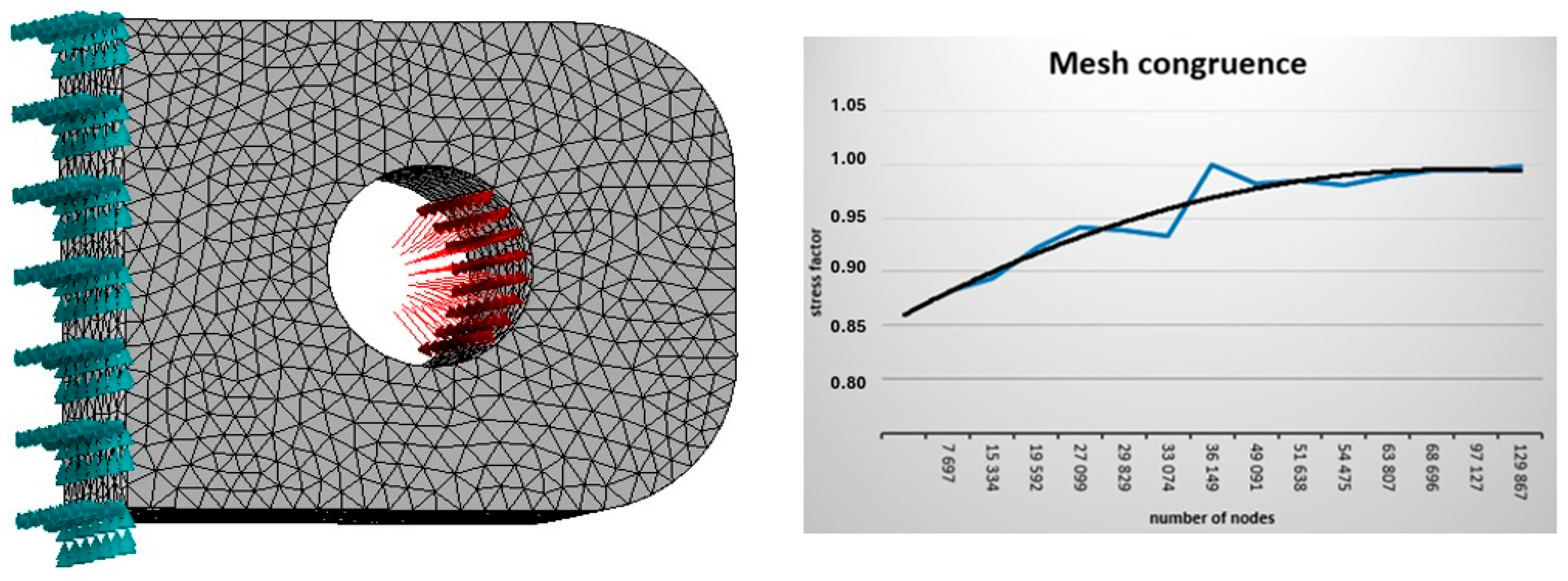
Another element of this study is the numerical analysis of the pre-designed MSC 23-150 folding bridge connection. Based on previous experience from the operation of folding bridges, a single pin connection bracket was analysed. Autodesk Inventor Nastran 2022 [33] software was used to carry out static-strength numerical analysis in the spatial stress state. In order to carry out the numerical calculations, a subdivision grid was assigned to the test object, whose recurrent solid element is a regular prism with the base of an equilateral triangle with 10 mm sides. The size of the elements resulted from the mesh fitting analysis, which showed that when the analysis was performed with approximately 33,000 calls (for an element with a side length of less than 14 mm), the difference in results did not vary by more than 5 per cent of the maximum stress value in the model at different finite element side dimensions (Figure 8). The mesh was selected based on the so-called stress criterion. When selecting a mesh with relatively large element dimensions, the calculation model was characterised by low accuracy due to the small number of elements and nodes between them. Gradually increasing the number of elements allowed for more accurate results corresponding to reality. It is worth noting that after obtaining satisfactory results, in which the stress values changed to a negligible extent, a specific number of finite elements was determined. The model of a single pin connector bracket was restrained to prevent movement and rotation in all directions in the area where the bracket joins the flat grating of the bridge structure. The support thus defined reflects the cooperation of the brackets and girder chords of the folding bridges. In the part of the connection where the surfaces of the pin and the single bracket come into contact, loads were applied in the form of distributed pressure on the contact surface. In the numerical calculations, a linear analysis was used with a static load of force P. The connection model and calculation results are shown in the figure below (Figure 8).
Loads in the model were applied to the surface of the actual contact area. Table 1 below shows the geometric parameters of this area for a value of the force P in the pin connection varying from 1000 [kN] to 2000 [kN], using Equations (1) and (3).
Through use of Equation (7) after changing the limits of the integral, assuming that the limits equal half the contact angle of the contact area, the values of the maximum stress σ β 2 were obtained for the individual connection forces analysed. The results of the calculation of the maximum pressure stress values are shown in Table 2.
In the table above, it can be seen that as the loading force in the connection increases, the contact area over which the load is distributed increases as well, and hence, the percentage increase in the stress value decreases.
Similarly, assuming the actual value of the pin–eye contact area angle, the values of the maximum tensile stress in section α-α were determined. The stress concentration factor for the limited contact area was determined from Equation (13), taking the value of the bending moment factor for the determined contact area angle from the formula:
α M Φ s = α M π 2 · c o s 2 90 Φ s + α M 0 · s i n 2 90 Φ s
where
α M 0 —coefficient of bending moments for the reduced contact area:
α M 0 = 5 π 8 16 = 0.482
The results of the calculations are presented below in Table 3.
Another component is the comparison of the results of the numerical calculations with the values determined analytically. Table 4 shows a comparison of the stress values in section β-β, and Table 5 compares the stress values in section α-α.
For comparison of the values obtained on the basis of the relationship to those from the EC standard [30], Table 6 was prepared, which contains the intensity of exertion of the structure in individual cross-sections. The values obtained on the basis of EC show lower intensity of exertion for the net cross-section, while when considering issues related to the possibility of free assembly of the pin within the serviceability limit state, the intensity of exertion reaches higher values. Lower intensity of exertion for the net cross-section is related to the EC standard allowing steel structural elements to operate within the plastic range, while on the other hand, higher intensity of exertion is related to bolt installation issues—a bolt that is too deformed is not suitable for reinstallation.
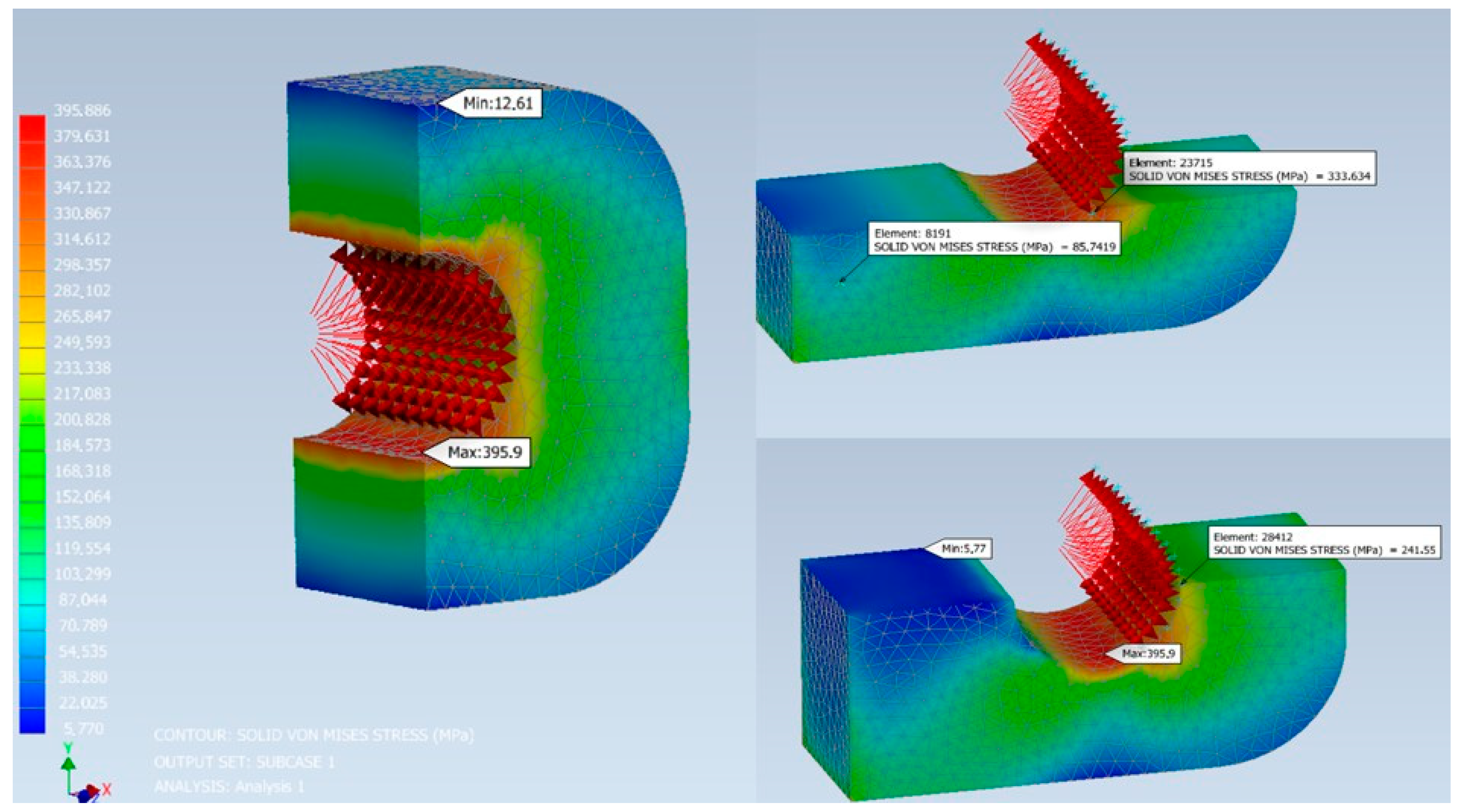
Figure 9 below shows the results of the numerical analysis of the spatial model of the designed single pin connection eye of the MSC 23-150 bridge. The locations of the calculated reduced stress values for a force value of P = 2000 kN at the connection are marked in the figure.
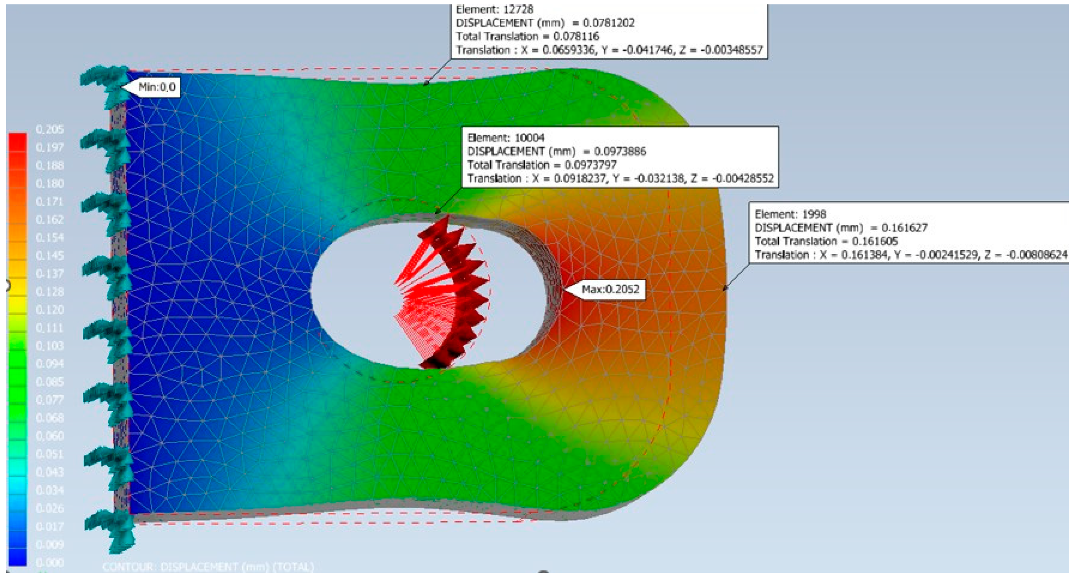
Another aspect presented is the connection deformation analysis. The deformation of the connection at the characteristic points of sections α-α and β-β is summarised below in Table 7. Figure 10 shows the deformation of the connection under a load of 2000 [kN].
From the results shown in the table above, it can be seen that the difference in deformation at the extreme points of section α-α varies within a small range. In section β-β, this difference increases more than the increase in load, by approximately 7% for every 200 kN increase in P force. This phenomenon is important from the point of view of stress concentration analysis. Due to the fact that the analysis is carried out in the elastic range, where deformations are relatively small, the deformation values have no direct implications for the assembly and use of the bridge. The values resulting from the applied force for the purposes of the analysis reach the measurement error limit for the diagnosis of prefabricated bridge structures, which is 0.1 mm. It should be added that the assembly and disassembly of truss sections, including pins in connections, take place after the deck has been removed. This is determined by the fact that a significant part of the load no longer affects this connection (live load and permanent load from deck slabs, kerbs, etc.). In view of the above, it can be concluded that the values obtained in the analysis do not affect the course of assembly and disassembly. However, they are important in terms of structural diagnostics—exceeding these values indicates that the structure may enter the plastic range of operation, which eliminates the element from future use.

5. Discussion

The computational and numerical analyses of the designed MSC 23-150 folding bridge connection show a high consistency of results. Analytical calculations are limited in the case of connections that are not circularly symmetrical, although they are very effective in determining stress concentration factors depending on the load size and assembly clearance δ. Naturally, the smaller the clearance size, the smaller the stress concentration factors in the connection (cf. Table 3). In addition, it is worth noting that the stress concentration factor takes into account the effects of both shear forces and axial forces occurring in the bridge joint by increasing the stresses in sections α-α and β-β. This is due to the size of the contact area of the connection; the height of the contact area and the contact angle are summarised below in Table 8.
Changing the assembly clearance δ significantly affects the results of the calculations; Table 9 below summarises the maximum stress values in the connection sections as a function of the force P in the pin connection.
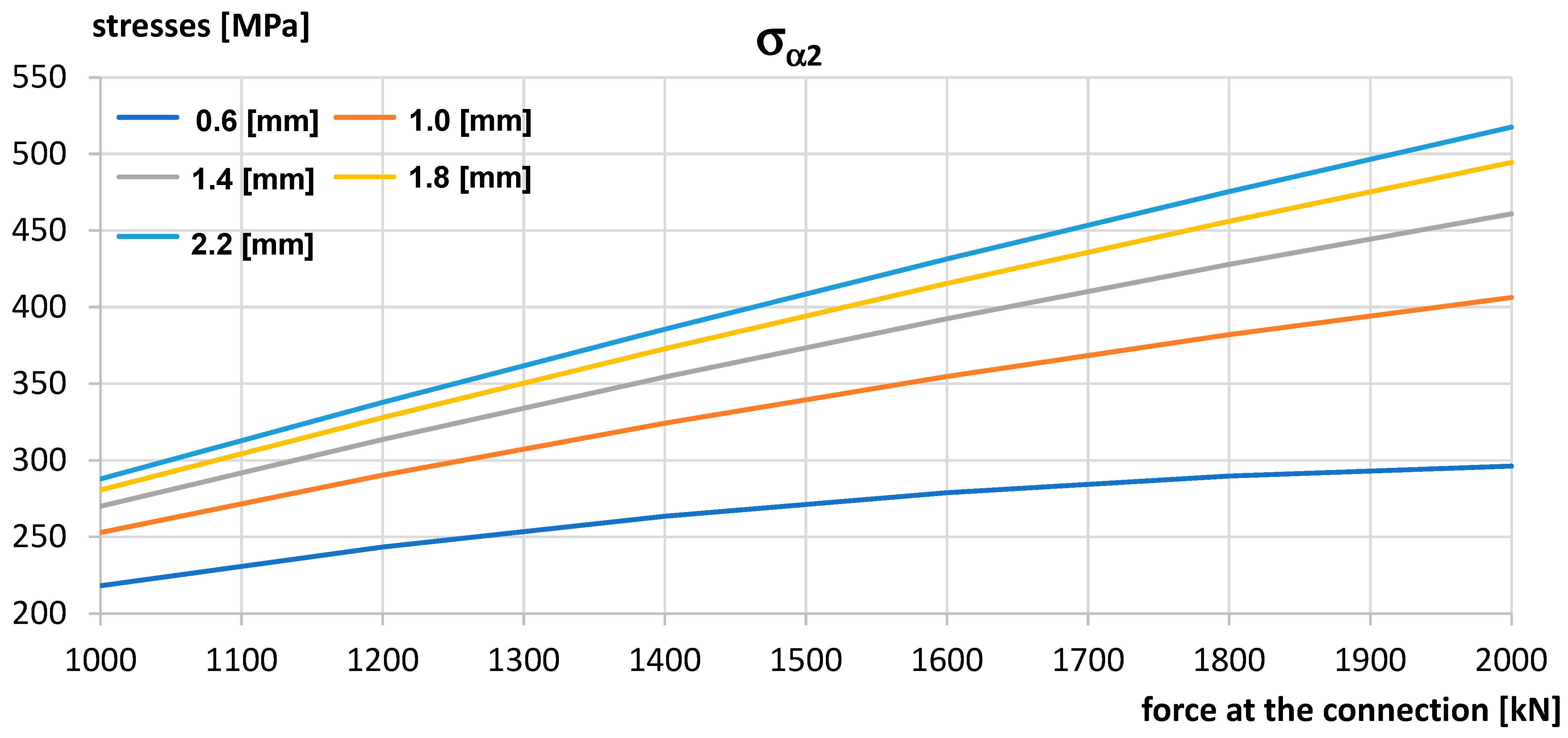
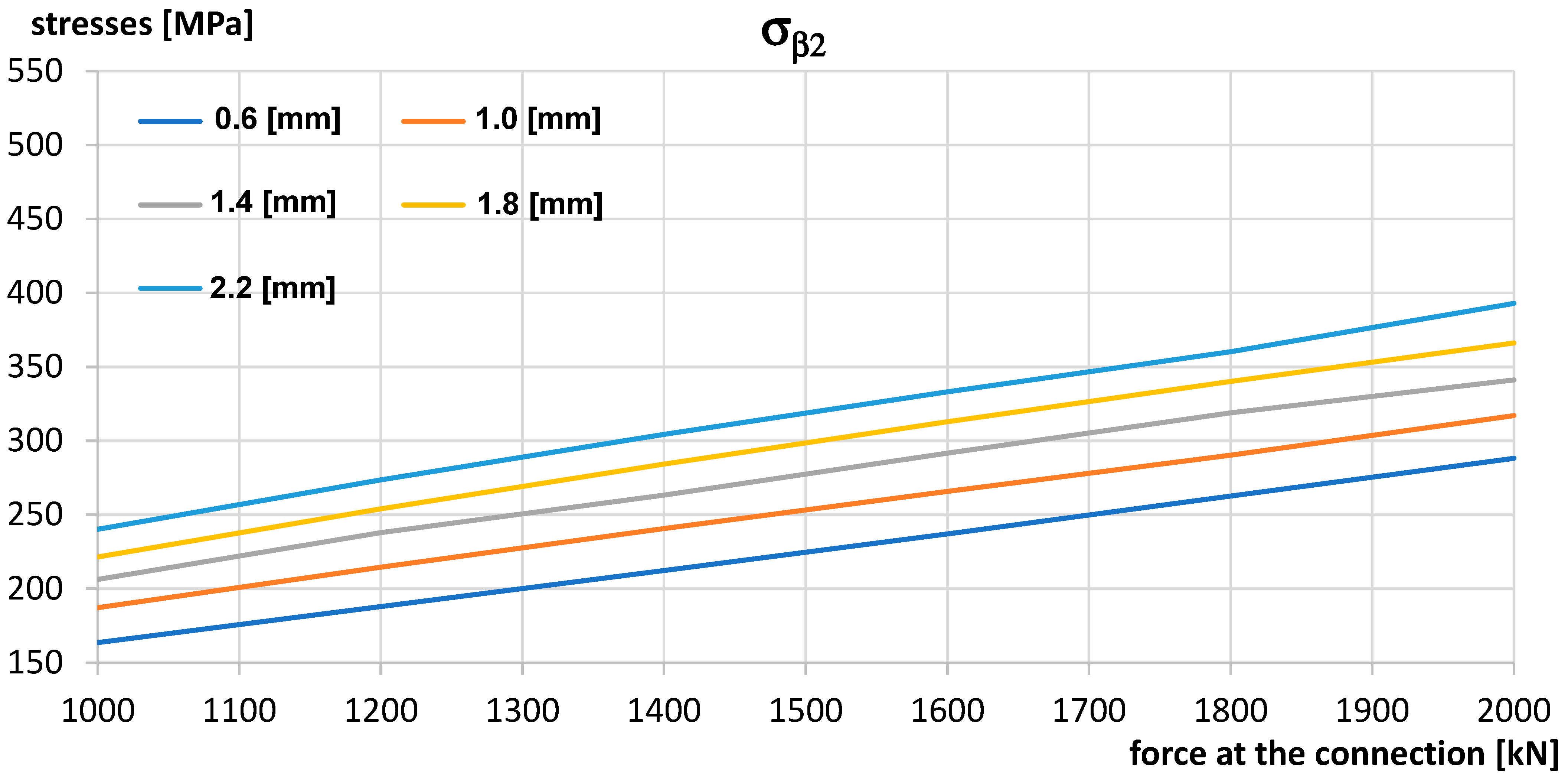
Figure 11 and Figure 12 show the effect of clearance on the maximum stress in sections α-α and β-β, determined according to Equations (7) and (16), respectively.
The diagrams show that the greater the clearance value, the greater the stress in the connection itself. It can also be seen that when the amount of assembly clearance is increased, there is a more rapid increase in stress in section α-α.
It is clearly evident that in order to achieve the most uniform distribution of stress in the connection, thereby achieving the most efficient use of material, the smallest possible assembly clearance should be used. Based on practical experience from the construction of folding bridges, the 1.0 mm assembly clearance currently used for folding bridges makes them possible to build under field conditions. Reducing this clearance to a value of 0.6 mm would provide a significant reduction in stress (in section α-α by more than 50 MPa), although the construction of a folding bridge could prove difficult, if not technically impossible, from the point of view of manual connection assembly/disassembly. The above considerations show that the optimal assembly clearance value for the operation of a folding bridge is 1.0 mm, which provides a compromise between the free assembly of its individual elements and the concentration of stresses in the pin connection. Figure 13 below shows the change in stress for two limit values of assembly clearance; the solid line indicates the stress in section α-α, while the stress in section β-β is marked with a dashed line. The diagram also shows that in the case of assembly clearance δ = 0.6 mm and a high value of force at the connection, the stress values in both sections are similar. In the case of assembly clearance of δ = 2.2 mm, the difference in stress values in the section increases, and the stress in the section increases more rapidly for section α-α. It is worth noting that during the operation of the connection, the normal stress in cross-section α-α, which is significantly correlated with the value of the assembly clearance, determines the stress level (Figure 11 and Figure 12). This means that in the case of a connector with a large assembly clearance, the potential point of loss of the connector’s load-bearing capacity is the cross-section. Therefore, it is extremely important to regularly check the technical condition of the components at this place in this type of structure during its use.

6. Conclusions

  • Due to the nature of folding bridge structures and in order to ensure the structural and operational safety of the bridges, material plasticisation is not permissible. This also applies to the pin connections themselves, both the eyes and the pins. Permanent deformation of the connector eyes can lead to an increase in kinematic deflection, while such deformation of the pins can make it impossible to reassemble the structure using them.
  • Based on the assumed pin connection meeting the load-bearing requirements for MSC 23-150 and based on calculations using the Herz formula [24,25,26], a method was proposed for taking assembly clearances into account in a bolted connection when calculating the stress on its components. The analytically obtained values were confirmed by the results obtained in numerical calculations, which proves the usefulness of this method.
  • Through use of an analytical method based on taking into account the actual contact area and a numerical method, the load-bearing capacity of the proposed connector was positively verified, which allows it to be used in the construction of the MSC 23-150 bridge. It is worth adding that preliminary calculations of the MSC 23-150 bridge showed that it would be possible to build crossings from this structure under the maximum military loads specified by MLC 150 (Military Load Classification). This will require the use of girders in a two-storey, three-wall arrangement and will enable free-span beam crossings of more than 80 m, with a limit of one vehicle per bridge span. The designed structure makes it possible to achieve significantly higher efficiencies, expressed in the square of the span by the weight [16], compared to the structures currently in use. The proposed solution enables the construction of crossings using proven technology by sliding the structure along an assembly track.
  • The designed connection will carry all loads that may be imposed on the bridge structure during its construction and use. Because of the significant reduction in the load-bearing capacity of the bridge structure due to potential asymmetry of the pin connection, efforts should be made to minimise the assembly clearance (gaps) between the connection eyes. The proposed slots of 0.6 mm on each side of the connection allow the structure to be assembled with the least possible asymmetric load on the pin. In addition, it minimises the risk of buckling of the top chord of the bridge structure in the horizontal plane.
  • In the analysis of pin connections, similar results were obtained using analytical and numerical methods. Based on convergence of analytical and numerical method results, it can be concluded that the proposed analytical method is a good tool to take into account the backlash on the design resistance of pin couplings in built-up bridges. Unfortunately, like any method, the numerical analysis is limited and makes certain assumptions. In view of the above, it is estimated that the margin of error for both methods may range from 5 to 10%. This is mainly due to the selection of the mesh size in the case of the numerical method and the approximations used for the analytical method. The analyses carried out in this paper are based on the assumption that the bridge pin connection only works in the elastic range, due to the cyclic nature of bridge rigging and the fact that bridge structures should not work in the plastic range. For the purpose of the analysis, it was assumed that the force acts on the joint in the direction parallel to the bridge axis. A further simplification is that the force acting on the joint is assumed to be a statically acting force. It is also worth mentioning the contact area between the pin and the joint component. The contact area of these elements was assumed on the basis of analytical calculations. Nevertheless, the results of the numerical and analytical analyses are similar, which demonstrates the suitability of the analytical method presented in this article for the calculation of pin joints of collapsible bridges.
  • The results of the analysis clearly indicate that as the force in the belts increases, the significance of the influence of assembly clearance on stress concentration decreases due to an increase in the contact area for specific assembly clearance values. However, taking the stress concentration factor into account causes an increase in the maximum normal stress in the bolted joint by up to 300%, which has a fundamental impact on determining the load-bearing capacity of this type of connection.
  • The next stage of research should be the validation of the numerical model and testing of the use of pins made of different materials or with different cross-section parameters, e.g., different stiffness. This is due to the simultaneous need to minimise assembly clearances in the connection and reduce the weight of the bolt. It is possible that bolts made of different material or composite material will exhibit different stiffness, which will affect the size of the so-called contact area between the pin and the bridge connector.

Author Contributions

E.M.: Conceptualisation, Data curation, Investigation, Writing—original draft, Validation, Visualisation, Writing—review and editing. R.C.: Conceptualization, Data curation, Investigation, Methodology, Supervision, Validation, Writing—review and editing. A.W.: Supervision, Writing—review and editing. A.O.: Writing—original draft, Visualisation. All authors have read and agreed to the published version of the manuscript.

Funding

This research received no external funding.

Data Availability Statement

The original contributions presented in this study are included in the article. Further inquiries can be directed to the corresponding author.

Conflicts of Interest

The authors declare no conflicts of interest.

Abbreviations

The following abbreviations are used in this manuscript:
ECEurocode
MLCMilitary Load Classification

References

  1. Białobrzeski, T. Portable Bridge; Communication and Connectivity Publishing House: Warsaw, Poland, 1978. [Google Scholar]
  2. Marszałek, J.; Jarzyna, J.; Bryda, P.; Chmielewski, R.; Jakubowski, G.; Marcinkowski, R.; Rymsza, J. Portable bridge. In Design, Construction, and Operation; GDDKiA: Warsaw, Poland, 2005. [Google Scholar]
  3. Benda, M.; Coufal, D.; Sobotka, J. Specific Aspects of Bridge Construction in the Central African Republic. Adv. Mil. Technol. 2016, 11, 253–260. [Google Scholar] [CrossRef]
  4. Ostrowska, A.; Chmielewski, R. Overview of the organisation and technology of portable panel bridges. Inżynieria Bezpieczeństwa Obiektów Antropog. 2023, 1, 46–52. [Google Scholar] [CrossRef]
  5. Wolniewicz, A.; Chmielewski, R. Diagnostics and operation of folding bridge structures used in civil transport construction. Logistyka 2016, 1, 137–143. [Google Scholar]
  6. Drozdowska, K. Concept for adapting the DMS-65 military folding bridge into a permanent structure. Bezpieczeństwo I Ekol. 2016, 6, 156–159. [Google Scholar]
  7. Andre, A.; Fernandes, J.; Ferraz, I.; Pacheco, P. New Modular Bridges Solutions, 9th International Symposium on Steel Bridges. Mater. Sci. Eng. 2018, 419, 012021. [Google Scholar] [CrossRef]
  8. Benda, M. Reach back possibility temporary bridges after floods in 2013. In Proceedings of the Medzinárodná Vedecká Konferencia, Riešenie Krízových Situácií v Špecifickom Prostredí, Žilina, Slovakia, 21–22 May 2014; pp. 59–66. [Google Scholar]
  9. Falkowski, M.; Mondel, A. Overview of US Army military bridges. Zesz. Nauk. WSOWL 2010, 156, 158–177. [Google Scholar]
  10. Russell, B.R.; Thrall, A.P. Portable and Rapidly Deployable Bridges: Historical Perspective and Recent Technology Developments. J. Bridge Eng. 2012, 18, 1074–1085. [Google Scholar] [CrossRef]
  11. Chmielewski, R.; Wolniewicz, A. Classification of the modernized DMS-65 folded bridge structure according to STANAG 2021 requirements. Roads Bridge—Drog. I Most. 2017, 16, 147–158. [Google Scholar] [CrossRef]
  12. Xu, G.Y.; Chu, O.; Jie, Z. Development of ZJ200 Portable Steel Bridge. Appl. Mech. Mater. 2012, 188, 123–129. [Google Scholar] [CrossRef]
  13. Defense Standard NO-54-A203:2020; Portable Bridges—General Requirements. MON: Warsaw, Poland, 2020.
  14. NATO Standardization Agency. STANAG 2021 JAS (Edition 6)—Military Load Classification of Bridges, Ferries, Rafts and Vehicles; NSA: Brussels, Switzerland, 2006. [Google Scholar]
  15. EN 1991-2; Eurocode 1: Actions on Structures—Part 2: Traffic Loads on Bridges. CEN: Brussels, Switzerland, 2003.
  16. Wang, Y.; Thrall, A.P.; Zoli, T.P. Adjustable module for variable depth steel arch bridges. J. Constr. Steel Res. 2016, 126, 163–173. [Google Scholar] [CrossRef]
  17. Zobel, H.; Karwowski, W. Polymer composites in bridge engineering: Multilayer bridges. Geoinżynieria: Drog. Mosty I Tunele 2006, 9, 42–49. [Google Scholar]
  18. Siwowski, T.; Zobel, H.; Al-Khafaji, T.; Karwowski, W. FRP Bridges in Poland: State of practice. Arch. Civ. Eng. 2021, 67, 5–27. [Google Scholar] [CrossRef]
  19. Lu, C.; Wang, X.; Ning, Y.; Wen, K.; Wang, Q. Numerical Investigation on the Structural Behavior of a Short-Span Cable-Stayed Bridge with Steel and CFRP Hybrid Cables. Materials 2024, 17, 2032. [Google Scholar] [CrossRef]
  20. Alomari, Q.A.; Linzell, D.G.; Zouriq, M.F.A. Response of Bare and CFRP-Retrofitted Multi-Column Piers Under Post-Fire-Coupled Vehicle Collision and Air Blast. Materials 2025, 18, 1449. [Google Scholar] [CrossRef]
  21. Dervishhasani, G.; Sennah, K.; Afefy, H.M.; Diab, A. Ultimate Capacity of a GFRP-Reinforced Concrete Bridge Barrier–Deck Anchorage Subjected to Transverse Loading. Appl. Sci. 2025, 15, 7771. [Google Scholar] [CrossRef]
  22. Xiong, J.; Ai, P.; Xu, J.; Yang, J.; Feng, P. A comprehensive study on CFRP rapid portable bridge: Design, experimental investigation and finite element analysis. Compos. Struct. 2022, 289, 115439. [Google Scholar] [CrossRef]
  23. Bursztynowski, Z. Stress analysis in folding bridge joints. Drog. Kolejowe 1990, 11, 177–180. [Google Scholar]
  24. Hertz, H. Über die Berührung fester elastischer Körper. J. Reine Angew. Mathem. 1881, 92, 156–171. [Google Scholar]
  25. Timoshenko, S.; Goodier, J.N. Theory of Elasticity; McGraw-Hill: New York, NY, USA, 1951. [Google Scholar]
  26. Duerr, D. Pinned connection strength and behaviour. J. Struct. Eng. 2006, 132, 182–194. [Google Scholar] [CrossRef]
  27. Choo, Y.S.; Choi, K.C.; Lee, K.H. The effects of eye bar shape and pin/hole tolerance on its ultimate strength. J. Constr. Steel Res. 1993, 26, 153–169. [Google Scholar] [CrossRef]
  28. Harms, I. Pinned Connections. Master’s Thesis, Delft University of Technology, Delft, The Netherlands, 2015. [Google Scholar]
  29. Conde, J.; da Silva, L.S.; Tankova, T.; Simões, R.R.; Abecasis, T. Design of pin connections between steel members. J. Constr. Steel Res. 2023, 201, 107752. [Google Scholar] [CrossRef]
  30. EN 1993-1-8; Eurocode 3: Design of Joints. CEN: Brussels, Switzerland, 2005.
  31. Montgomery, J.; Higgins, C.D.; Liu, J. Capacities of Pin and Hanger Assemblies. In Phase 1—Report Number: CA18-3023; Oregon State University: Corvallis, OR, USA, 2018. [Google Scholar]
  32. Cios, K.; Krasoń, W. Selected aspects of numerical analysis of a scissor bridge joint. Mechanik 2015, 7, 592–594. [Google Scholar] [CrossRef]
  33. Autodesk Inventor Nastran; Software for 3D Modeling and Numerical Calculations; Autodesk Company: San Francisco, CA, USA, 2022.
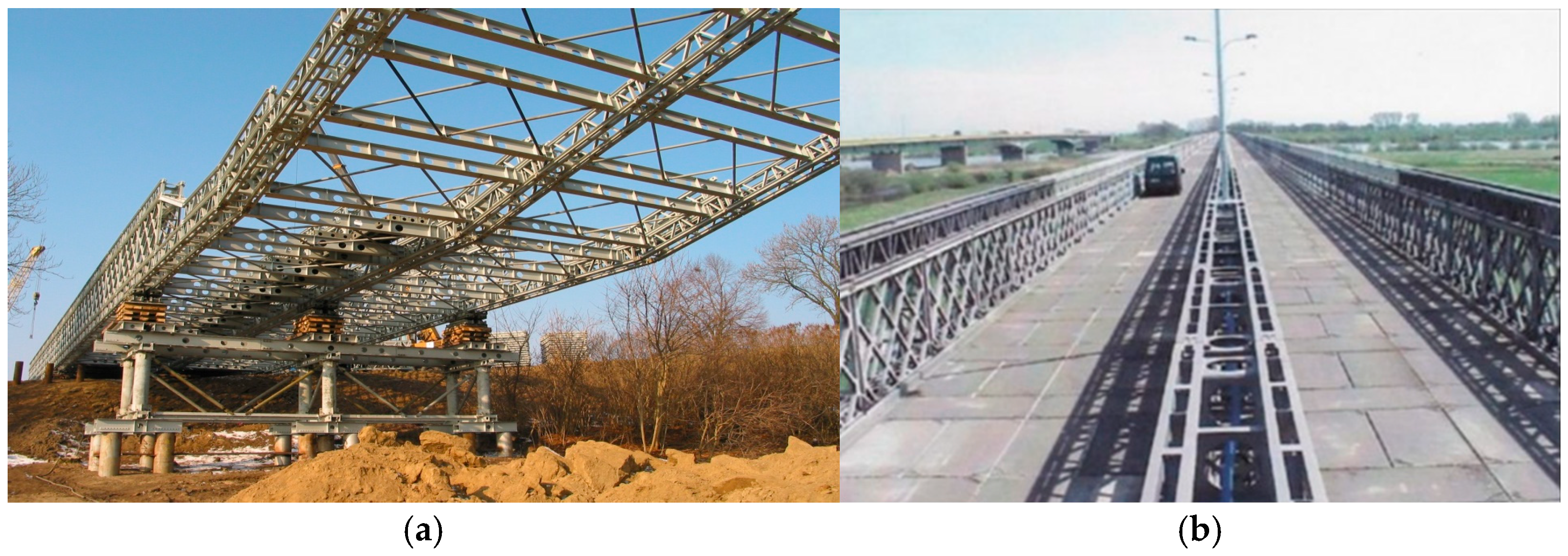
Figure 1. DMS-65 triple-girder two-lane bridge over the Vistula River in Kiezmark (Poland): (a) structure in the sliding process; (b) a view of bridge deck.
Applsci 15 10047 g001
Figure 2. Concept of the new folding road bridge—an overview of the load-bearing structure MSC 23-150 with its components marked: (1) girders, (2) truss chord, (3) crossbeam, (4) composite deck, and (5) girder concentration.
Applsci 15 10047 g002
Figure 3. Change in bending moment due to assembly clearances in pin connections of folding bridges.
Applsci 15 10047 g003
Figure 4. Diagram of the effect of assembly clearances on the static scheme of a folding bridge structure—(a) the angle of rotation between the sections of the folding bridge; (b) the deflection due to assembly clearance in the pin connections.
Applsci 15 10047 g004
Figure 5. Geometry of pin connection with load—longitudinal cross-section.
Applsci 15 10047 g005
Figure 6. Diagrams of pin eye loading: (a) “full” contact area; (b) reduced area—concentrated force; (c) “limited” contact area.
Applsci 15 10047 g006
Figure 7. Geometrical parameters of the three parts of the MSC 23-150 pin connection, with dimensions in [mm].
Applsci 15 10047 g007
Figure 8. Spatial computational model of the MSC 23-150 single pin connection bracket with the actual contact area load and results of FEM (Finite Element Method) mesh selection analysis.
Applsci 15 10047 g008
Figure 9. Reduced stress map according to the Huber–Mises strength hypothesis [MPa] in the MSC 23-150 single pin connection bracket: results of the numerical analysis for a loading force of 2000 kN at the connection.
Applsci 15 10047 g009
Figure 10. Deformation map of the MSC 23-150 single pin connection bracket: results of the numerical analysis for a loading force of 2000 kN at the connection.
Applsci 15 10047 g010
Figure 11. Diagram of maximum stress values in section α-α depending on the assembly clearance δ.
Applsci 15 10047 g011
Figure 12. Diagram of maximum stress values in section β-β depending on the assembly clearance δ.
Applsci 15 10047 g012
Figure 13. A diagram of the variation in the maximum stress value in the pin connection sections for the values of assembly clearance δ = 0.6 and 2.2 mm.
Applsci 15 10047 g013
Table 1. Contact angle value of the contact area in the pin connection depending on the loading force.
Force at the Connection [kN]Contact Area Height b [mm]Contact Angle of the Contact Area 2Φs [°]
100059.6981.97
120063.4388.37
140066.7794.40
160069.81100.19
180072.60105.85
200075.20111.45
Table 2. Values of pressure stresses in section β-β obtained analytically depending on the value of the loading force in the connection.
Force at the Connection [kN]Maximum Stress in Section β-β in a Single Pin Connection EyePercentage Increase in the Stress Value [%]
Output   Stress   σ 0 [MPa] Stress   After   Contact   Area   Reduction   σ β 2 [MPa]
1000113.38187.2965.19
1200136.05214.6657.77
1400158.73240.6751.62
1600181.41265.7846.51
1800204.08290.3742.28
2000226.76317.1939.88
Table 3. Tensile stress values in section α-α obtained analytically depending on the value of the loading force at the connection.
Force at the Connection [kN]Unit Stress
σ N [MPa]
Stress   Concentration   Factor   k α 2   Φ s Maximum   Stress   σ α 2 [MPa]
100079.103.20252.87
120094.923.06290.31
1400110.742.93324.22
1600126.562.80354.78
1800142.382.68382.09
2000158.202.57406.34
Table 4. Comparison of pressure stress values in section β-β.
Force at the Connection [kN]Stress (Analytical Method)
σ β 2 [MPa]
Stress From the Model (Numerical Method) σβM [MPa]Maximum Model Stress
(Numerical Method)
σβMmax [MPa]
σ β Mmax / σ β 2 [%]
1000187.29148.00192.59102.83%
1200214.66164.63217.72101.43%
1400240.67185.50256.34106.51%
1600265.78196.10272.26102.44%
1800290.37218.33298.57102.82%
2000317.19241.55333.63105.18%
Table 5. Comparison of tensile stress values in section α-α.
Force at the Connection [kN]Stress (Analytical Method)
σ α 2 [MPa]
Stress from the Model (Numerical Method) σαM [MPa] σ αM / σ α 2 [%]
1000252.87227.489.93%
1200290.31263.590.76%
1400324.22296.191.33%
1600354.78330.293.07%
1800382.09363.195.03%
2000406.34395.997.43%
Table 6. Comparison of stresses in the net cross-section and under compression obtained taking into account the real contact area and based on Eurocode [30].
Force at the Connection F E d [kN]Intensity in Cross Section α-α
σ α 2 / f y z
Net Cross-Sectional Stress Obtained on the Basis of EC
F E d / V e f f
Intensity in Cross Section β-β
σ β 2 / f y z
Compressive Stress Obtained on the Basis of EC
F E d / F b , R d , s e r
20000.920.720.720.86
Table 7. Comparison of connection line deformation in sections α-α and β-β.
Force at the Connection [kN]Displacement
δ α 2 [mm]
Displacement
δ α 1 [mm]
Displacement
δ β 2 [mm]
Displacement
δ β 1 [mm]
10005.95 × 10−24.73 × 10−212.53 × 10−29.58 × 10−2
12006.85 × 10−25.49 × 10−214.46 × 10−211.17 × 10⁻²
14007.63 × 10−26.12 × 10−216.12 × 10−212.49 × 10⁻²
16008.22 × 10−26.69 × 10−217.58 × 10−213.70 × 10⁻²
18008.65 × 10−27.20 × 10−218.94 × 10−214.81 × 10⁻²
20009.33 × 10−27.81 × 10−220.52 × 10−216.15 × 10⁻²
Table 8. Contact area, with parameters depending on the loading force at the connection P and the clearance δ, determined according to Equations (1)–(3).
Clearance [mm]0.61.41.82.2
Force [kN]b [mm]2Φs [°]b [mm]2Φs [°]b [mm]2Φs [°]b [mm]2Φs [°]
100070.87102.3053.2771.6748.9265.0445.6960.27
120075.31111.7056.6176.9451.9869.6848.5564.48
140079.28121.2059.6081.8354.7373.9451.1168.34
160082.89131.2562.3186.4357.2277.9253.4371.92
180086.21142.6564.8090.8259.5181.6855.5775.28
200089.29157.7567.1295.0561.6485.2757.5678.47
Table 9. Values of maximum stresses in sections α-α and β-β.
Clearance [mm]0.61.41.82.2
Force [kN] σ α 2 [MPa] σ β 2 [MPa] σ α 2 [MPa] σ β 2 [MPa] σ α 2 [MPa] σ β 2 [MPa] σ α 2 [MPa] σ β 2 [MPa]
1000218.18163.69270.06206.34280.63221.54287.89240.25
1200243.32188.00313.62238.01327.94254.04337.79273.62
1400263.47212.31354.36263.38372.87284.36385.60304.40
1600278.87237.09392.41291.71415.54312.94431.45333.12
1800289.73262.67427.91318.96456.05340.15475.41360.23
2000296.24288.30460.94341.22494.49366.28517.55392.94
Disclaimer/Publisher’s Note: The statements, opinions and data contained in all publications are solely those of the individual author(s) and contributor(s) and not of MDPI and/or the editor(s). MDPI and/or the editor(s) disclaim responsibility for any injury to people or property resulting from any ideas, methods, instructions or products referred to in the content.