Article

Wheel–Rail Vertical Vibration Due to Random Roughness in the Presence of the Rail Dampers with Mixed Damping System

1
Department of Railway Vehicles, National University of Science and Technology Politehnica Bucharest, 060042 Bucharest, Romania
2
Doctoral School of Mechanical Engineering and Mechatronics, National University of Science and Technology Politehnica Bucharest, 060042 Bucharest, Romania
*
Authors to whom correspondence should be addressed.
Appl. Sci. 2025, 15(18), 10027; https://doi.org/10.3390/app151810027
Submission received: 7 August 2025 / Revised: 7 September 2025 / Accepted: 10 September 2025 / Published: 13 September 2025

Abstract

In this paper, the vibration of a wheel running on a light rail equipped with rail dampers that use a mixed damping system (rubber–oil) is investigated under the excitation of random roughness on the rolling surfaces, to demonstrate the influence of such rail dampers on the dynamic behaviour at the wheel–rail interface. For this purpose, a model is adopted in which a rigid wheel moves at constant speed over a rail modelled as an infinite Timoshenko beam, supported by elastic foundations with an internal degree of freedom that represents the behaviour of the rail pads, sleepers, and ballast. The rail dampers are represented as two-mass oscillators, while the internal friction in the elastic components of the wheel–rail system is modelled using hysteretic damping. To obtain the time series of the rail and wheel displacements, as well as the wheel–rail contact force, the convolution theorem is applied in a heuristic manner, making use of the relationship between Green’s functions in the time and frequency domains through direct and inverse Fourier transforms. The results show that (a) rail dampers primarily affect rail dynamics and the wheel–rail contact force over a relatively wide frequency range, while having little influence on wheel motion; (b) rail dampers are highly effective in reducing rail vibration and the wheel–rail contact force when the rail pads are stiff, but considerably less effective when soft rail pads are used; and (c) they may slightly amplify the contact force at the lower edge of their effective frequency range.

1. Introduction

Although rail transport is recognised as being less polluting compared to other means of land transport, train traffic is accompanied by a multitude of noise sources that affect both the comfort conditions in passenger cars and the populated areas in the vicinity of the railway [1]. The most intense source of noise is the wheel–rail system, whose vibrations, excited by the irregularities of the running surfaces, are the main cause of rolling noise. Rolling noise is considered the dominant source of train noise at speeds between 50 km/h and 300–350 km/h, as reported by various sources [2,3].
Vibration dampers, which work on the dynamic absorber principle [4], are a source-level solution for rolling noise. They can be installed on rails [5,6] or on wheels [7,8], depending on their configuration.
Typically, rail dampers are made from a massive rubber block with a parallelepiped shape, having two faces moulded to fit the surface between the rail web and base. Inside the rubber block, there are one or two massive metal pieces (usually steel). Rail dampers are installed in pairs at the midpoint between sleepers, either using metal clamps or by adhesive bonding [9,10,11].
From a mechanical perspective, these dampers behave like oscillators with one or two degrees of freedom attached to the rail [12,13].
The vibration of the rail, initiated at the wheel–rail contact zone, propagates along the track in the form of bending waves and is transmitted to the dampers. In this way, the dampers absorb part of the wave energy and dissipate it as heat through the out-of-phase vibration of the metal elements, due to the hysteretic damping of the rubber block.
The effect of the rail dampers consists in reducing the propagation distance of the rail’s bending waves and, consequently, the acoustic power radiated by the rail [14,15].
Under these conditions, it is logical that the effectiveness of rail dampers is quantitatively assessed using the so-called track decay rate [16,17]. This parameter expresses the attenuation of bending waves propagating through the rail per unit length of the track, and is measured in dB/m. Moreover, the track decay rate is a standardised parameter used in the assessment of rolling noise [18].
Many studies have aimed to evaluate the performance of different types of rail dampers in terms of their ability to increase the track decay rate for noise control, either through theoretical modelling [9,14,16,19,20,21,22,23,24,25] or through laboratory experiments and field tests [9,13,26,27,28]. Other studies have highlighted the ability of rail dampers to limit the initiation and development of rail corrugation [10,29,30,31].
In the theoretical studies cited above, the vibration of rails equipped with rail dampers was analysed using models based either on analytical formulations, such as the Euler–Bernoulli beam theory [10] and the Timoshenko beam theory [14,19,21,22,24,25], or on numerical methods, such as the finite element method [29,30,31]. In most cases, the rail vibration problem is addressed in the frequency domain, which implies that the excitation force has a fixed position relative to the rail. This is particularly true for studies investigating the influence of rail dampers on the decay rate of the track and, implicitly, on rolling noise [16]. This approach is often preferred, for reasons of simplicity, even in studies analysing the wheel–rail interaction in the presence of rail dampers [22,24]. Another important advantage lies in the possibility to use the hysteretic damping model, which more accurately describes the vibration behaviour of both the elastic components of the track and the rail dampers [14,16,19,24,25].
However, two key limitations of frequency-domain analysis should be noted. First, when a harmonic force travels along an elastic structure, such as a rail, the propagation speed of the induced elastic waves depends on the direction of propagation, which consequently alters its dynamic behaviour. Second, parametric excitation can occur when a moving force acts on an elastic structure with spatial periodicity, such as a ballasted track.
To overcome these limitations, rail vibration is analysed in the time domain, which involves the use of modal analysis, as is typically done in models based on the finite element method. In this context, linear damping models such as Kelvin–Voigt or Maxwell are commonly applied [10,29,30,31].
This paper analyses the vibration of the wheel–rail system caused by random irregularities of the running surfaces, in the presence of rail dampers with a hybrid damping system (rubber–oil). The study represents an application of tuned mass dampers in the field of vibration control of the wheel–rail system. Unlike the predominantly theoretical approaches discussed in the cited works [10,12,14,16,19,20,21,22,23,24,25,29,30,31], the present work investigates the dynamic behaviour at the wheel–rail interface—both in steady-state and forced regimes—resulting from the use of dampers with a hybrid damping system on the rail. In addition, it presents a numerical method that enables the implementation of hysteretic damping in time-domain analysis.
Figure 1 shows these dampers, which are designed for installation on light rails (49E1 [32]). A general description can be found in references [11,33], while the experimental results used to determine the parameters of the dampers—modelled as a two-degree-of-freedom oscillator—are presented in [11]. The performance of these rail dampers in terms of track decay rate was theoretically evaluated in [33]. An analytical model was developed, representing the rail as an infinite Timoshenko beam with two types of periodically attached oscillators: one modelling the rail–pad–sleeper–ballast system, and the other representing the dampers. A similar modelling approach has been employed in numerous studies, as mentioned above [14,19,21,22,24,25]. The hysteretic damping model has been implemented to represent the internal friction in the elastic components. The decay rate was subsequently determined using the Green’s functions of the rail in the frequency domain.
This paper adopts the previously presented model of a rail equipped with dampers to investigate the vibration of a moving wheel under the influence of surface irregularities. Particular attention is given to the effect of the rail dampers on the quantities that describe the dynamic behaviour at the wheel–rail interface: the wheel displacement, the rail displacement at the contact point, and the contact force. To compute the time functions of these quantities, the convolution theorem is heuristically applied to the wheel–rail contact equation, using the relationship between the rail’s Green’s functions in the time and frequency domains, by means of direct and inverse Fourier transforms. Using this method, the influence of rail dampers with a hybrid damping system was studied both on the steady-state wheel–rail interaction and on vibrations caused by surface irregularities. The parametric study considered the stiffness of the rail pads (stiff/soft) and the sleeper spacing (short/long), and identified the frequency ranges in which the dampers are effective.

2. Mechanical Model of a Moving Wheel on a Rail with Rail Dampers

Figure 2 shows the mechanical model of a moving wheel on a rail featured with rail dampers. The wheel is considered a rigid body with mass Mw moving at constant speed V along the rolling surface of a rail affected by the random roughness r(x), where x is the spatial coordinate along the rail of the reference frame Oxz. The wheel is subjected to a static load Qo.
The rail model is based on the Timoshenko theory applied to an infinite uniform beam. The parameters for the rail model are E and G—the longitudinal and shear modulus of elasticity; ρ—the density; S—the cross-section area; I—the moment of inertia; and κ—the shear coefficient.
The rail is supported on a ballast bed through an infinite row of equally spaced semi-sleepers and rail pads. Each semi-sleeper is considered as a rigid body, while the corresponding rail pad and ballast are modelled as elastic elements. The parameters for the rail support are Ms—the mass of ½ sleeper; kp—the stiffness of the rail pad; kb—the ballast stiffness; li—the position of the i-th semi–sleeper; and l—the sleeper bay.
Two rail dampers are attached to the rail in the midpoint of each sleeper bay. These two rail dampers are represented by an equivalent two-mass oscillator. The parameters of this oscillator are M1, M2—the masses of the upper and lower bodies; k1,2—the stiffness of elastic elements; and ai—the position of the i-th rail damper.
All elastic elements of the model—except for the elastic wheel–rail contact—are assumed to have hysteretic damping, as follows: η—the loss factor of the rail material, ηp—the loss factor of the rail pad, ηb—the loss factor of the ballast and η1,2—the loss factor of the elastic elements of the rail damper.
The motion of the model components with respect to the Oxz reference frame is described by the vertical displacement of the wheel zw(t); the rail displacement w(x,t); the cross-section rotation θ(x,t); the displacement of the i-th semi–sleeper zi(t); and the displacements of the rigid bodies of the i-th rail damper z1i,2i(t).
The wheel–rail contact is modelled using a nonlinear elastic element, based on Hertz’s theory for the contact between two elastic bodies [34]:
z w ( t ) w ( V t , t ) r ( V t ) = Q ( t ) C H 2 / 3 ,
where Q(t) is the wheel—rail contact force and CH is the Hertzian constant.
The solution to Equation (1) can be constructed based on the time--domain Green function of the rail displacement, gw(x,ξ,t), which is related to the frequency-domain Green function of the rail displacement (receptance), Gw(x,ξ,ω), via the inverse Fourier transform
g w ( x , ξ , t ) = 1 2 π G w ( x , ξ , ω ) e i ω t d ω .
Time-domain Green function of the rail displacement is a real function and represents the rail response in the x section at moment t to a unit impulse force applied in the ξ section at t = 0. The frequency-domain Green function of the rail displacement is a complex function; it represents the frequency response function of the rail in the x section when a unit harmonic impulse force of an angular frequency ω is applied in the ξ section.
The frequency-domain Green function of the rail displacement can be calculated using the following equations [33]:
-
For the rail:
G ¯ S κ d 2 w ¯ ( x , ω ) d x 2 d θ ¯ ( x , ω ) d x + ω 2 m w ¯ ( x , ω ) = F ¯ δ x ξ + k ¯ p i = w ¯ ( l i , ω ) z ¯ t i ( ω ) δ x l i + k ¯ 1 i = w ¯ ( a i , ω ) z ¯ 1 i ( ω δ x a i , E ¯ I d 2 θ ¯ ( x , ω ) d x 2 + G ¯ S κ d w ¯ ( x , ω ) d x θ ¯ ( x , ω ) + ω 2 ρ I θ ¯ ( x , ω ) = 0 ,
-
For the sleeper ‘i’
ω 2 M t + k ¯ p + k ¯ b z ¯ t i ( ω ) k ¯ p w ¯ ( l i , ω ) = 0 ,
-
For the rail damper ‘i’
ω 2 M 1 + k ¯ 1 + k ¯ 2 z ¯ 1 i ( ω ) k ¯ 1 w ¯ ( a i , ω ) k ¯ 2 z ¯ 2 i ( ω ) = 0 , ω 2 M 2 + k ¯ 2 z ¯ 2 i ( ω ) k ¯ 2 z ¯ 1 i ( ω ) = 0
where w ¯ ( x , ω ) , θ ¯ ( x , ω ) , z ¯ t i ( ω ) , z ¯ 1 , 2 i ( ω ) and F ¯ are the complex amplitudes,
k ¯ p , b = k p , b ( 1 + i η p , b ) , k ¯ 1 , 2 = k 1 , 2 ( 1 + i η 1 , 2 )
are the complex stiffnesses and
E ¯ = E ( 1 + i η ) , G ¯ = G ( 1 + i η )
are the complex elastic moduli.
The following boundary conditions must be considered
lim x w ¯ ( x ) = 0 .
Equations (3)–(7) can be solved to calculate the complex amplitude of the rail displacement in the section x, w ¯ ( x , ξ , ω ) , when a harmonic force of amplitude F ¯ and angular frequency ω is applied in the section ξ. To this end, the method presented in ref. [33] can be applied. Then, the frequency-domain Green function results as
G ( x , ξ , ω ) = w ¯ ( x , ξ , ω ) F ¯ .
Inserting Equation (8) in Equation (2), the time-domain Green function results, but this function has an imaginary part because of the hysteretic damping model. To eliminate the imaginary part of the gw(x,ξ,t) function due to the hysteretic damping model, the frequency-domain Green function must be Hermitian [34], which implies
Re G ( x , ξ , ω ) = Re G ( x , ξ , ω ) ,   Im G ( x , ξ , ω ) = Im G ( x , ξ , ω ) .
The first condition is accomplished ‘naturally’ due to the symmetry of the real part of the frequency-domain Green function with respect to the ω coordinate, but the second condition is not satisfied because the imaginary part of the Gw(x, ξ, t) function is an even function.
However, taking
k ¯ p , b = k p , b 1 + i η p , b sig ( ω ) , k ¯ 1 , 2 = k 1 , 2 1 + i η 1 , 2 sig ( ω ) , E ¯ = E 1 + i η sig ( ω ) ,   G ¯ = G 1 + i η sig ( ω ) ,
the imaginary part of the Gw(x, ξ, t) function becomes an odd function without affecting the value of the frequency-domain Green function for positive angular frequency [34].
With this in mind, the time-domain Green function can be calculated:
g w ( x , ξ , t ) = 1 2 π G w ( x , ξ , ω ) e i ω t d ω = 1 2 π Re G w ( x , ξ , ω ) cos ω t Im G w ( x , ξ , ω ) sin ω t d ω = 1 π 0 Re G w ( x , ξ , ω ) cos ω t Im G w ( x , ξ , ω ) sin ω t d ω
because both terms under integral are even functions.
The result of the integral in Equation (12) is not causal [35]; however, the values for t < 0 can be neglected, as they are small (as will be shown in Section 3.2). Therefore, only the values for t > 0 are retained, leading to Equation (13), where σ(.) denotes the Heaviside step function:
g w ( x , ξ , t ) = σ ( t ) 1 π 0 Re G w ( x , ξ , ω ) cos ω t Im G w ( x , ξ , ω ) sin ω t d ω .
The effectiveness of this approach can be evaluated by comparing between the frequency-domain Green function calculated with Equation (9) and the result obtained by applying the Fourier transform in Equation (13)
G w ( x , ξ , ω ) = g w ( x , ξ , t ) e i ω t d t = 0 g w ( x , ξ , t ) ( cos ω t i sin ω t ) d t
Applying the convolution theorem, the rail displacement at the contact point reads
w ( V t , t ) = 0 t g w ( V t , ξ , t τ ) Q ( τ ) δ ( ξ V τ ) d τ d ξ = 0 t g w ( V t , V τ , t τ ) Q ( τ ) d τ
The wheel displacement is given as
z w ( t ) = 0 t h ( t τ ) Q o Q ( τ ) d ξ ,
where h(t) is the time-domain Green function of the wheel
h ( t ) = t M w .
Inserting the Equations (14) and (15) into the wheel–rail contact Equation (1) yields
0 t h ( t τ ) Q o Q ( τ ) d τ + 0 t g w ( V t , V t , t τ ) Q ( τ ) d τ Q ( t ) C H 2 / 3 = r ( V t ) ,
which is a nonlinear integral equation.
The unknown variable in Equation (16) is the contact force at time t, Q(t). This equation can be solved using a discretisation approach with an appropriate time step Δt, followed by the numerical method described in Ref. [36]. Then, the rail and wheel displacement can be calculated using the Equations (14) and (15).
The nonhomogeneous term in the contact Equation (16) is the rail roughness profile, which can be represented as a pseudo–random function obtained from the power spectral density of the roughness.
In the following, the shape of the power spectral density of the roughness is [37]
S ( Ω ) = K r Ω + Ω o Ω n ,
where Ω is the wavenumber, Kr—coefficient, Ωo—constant, and n—exponent.
Power spectral density of the roughness can be discretised between the limits Ωmin and Ωmax using an adequate step ΔΩ = Ωi − Ωi–1, for calculating the corresponding roughness amplitude
r i = 2 Ω i 1 Ω i S ( Ω ) d Ω = 2 K r n 2 1 Ω i 1 n 2 1 Ω i n 2 + Ω o n 1 1 Ω i 1 n 1 1 Ω i n 1 .
Then, the pseudo-random function of the roughness reads
r ( x ) = i = 1 N r r i sin Ω c i x + φ i ,
where x is the coordinate along the rail, Ωci is the middle of the i interval, Nr—number of discrete components of the pseudo-random roughness function, and φi is the random value of the initial phase of the i component.

3. Numerical Application

This section deals with the numerical study of the wheel–rail vibration due to the random roughness of the rolling surfaces in the presence of the rail dampers.
Table 1 lists the parameter values of the wheel–rail with the rail dampers model.
The wheel mass and static load correspond to a passenger coach, while the rail and discrete supports follow those in Ref. [33]. The rail damper parameters were determined from experimental data [11].

3.1. Pseudo-Random Function of the Roughness

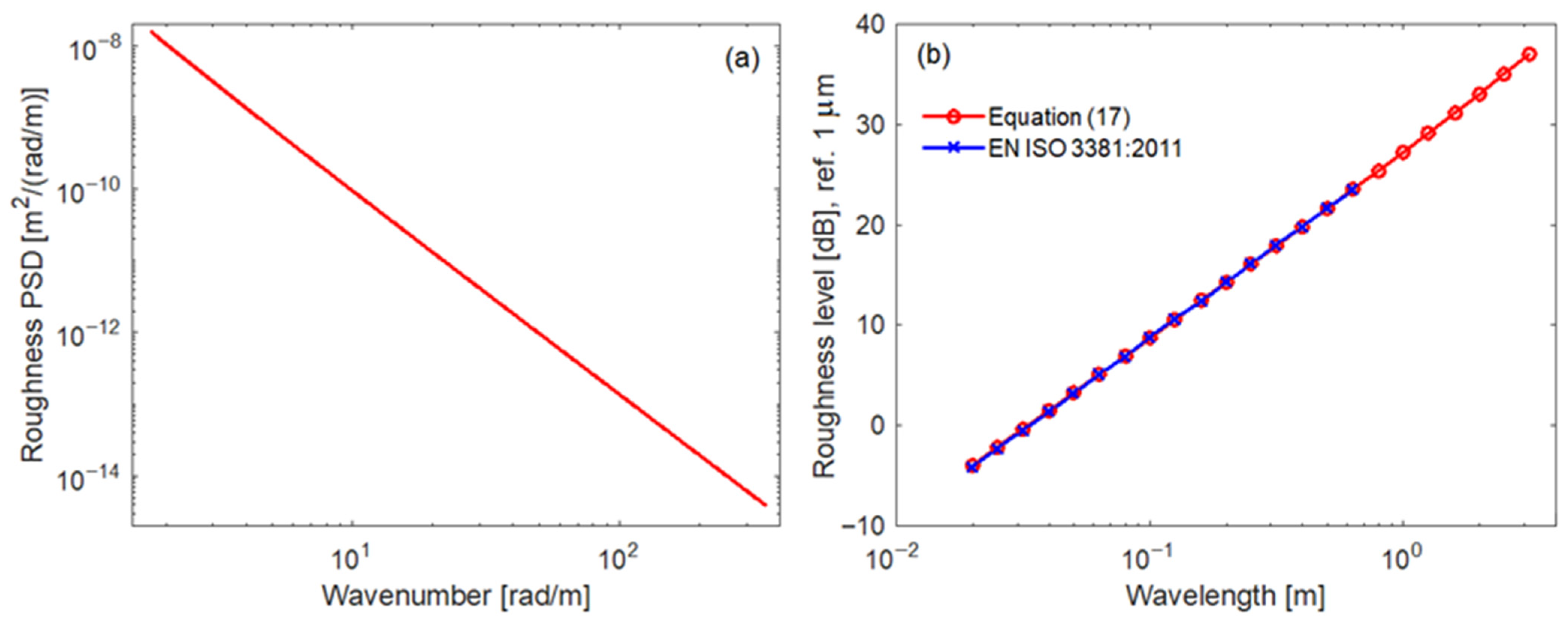
Figure 3 presents the roughness PSD given by Equation (17) and the roughness level calculated using this equation. The roughness level obtained from Equation (17) is very close to the maximum roughness level allowed in railway applications [38].
Figure 4 shows the pseudo-random roughness function distilled from the roughness PSD given by Equation (17), along with its amplitude spectrum calculated for 60 m/s. The mean value of the roughness is −0.08901 μm, and its RMS value is 119.745 μm. At 60 m/s, the amplitude spectrum of the roughness spans the frequency range between 17 Hz and 3371 Hz.
For a different speed, v, the frequency limits of the amplitude spectrum change according to the relation
f v = f v o v v o
where f v o is the frequency of the spectrum at vo = 60 m/s.

3.2. Green Functions

In this section, the correctness of the method for calculating the time-domain Green function is evaluated.
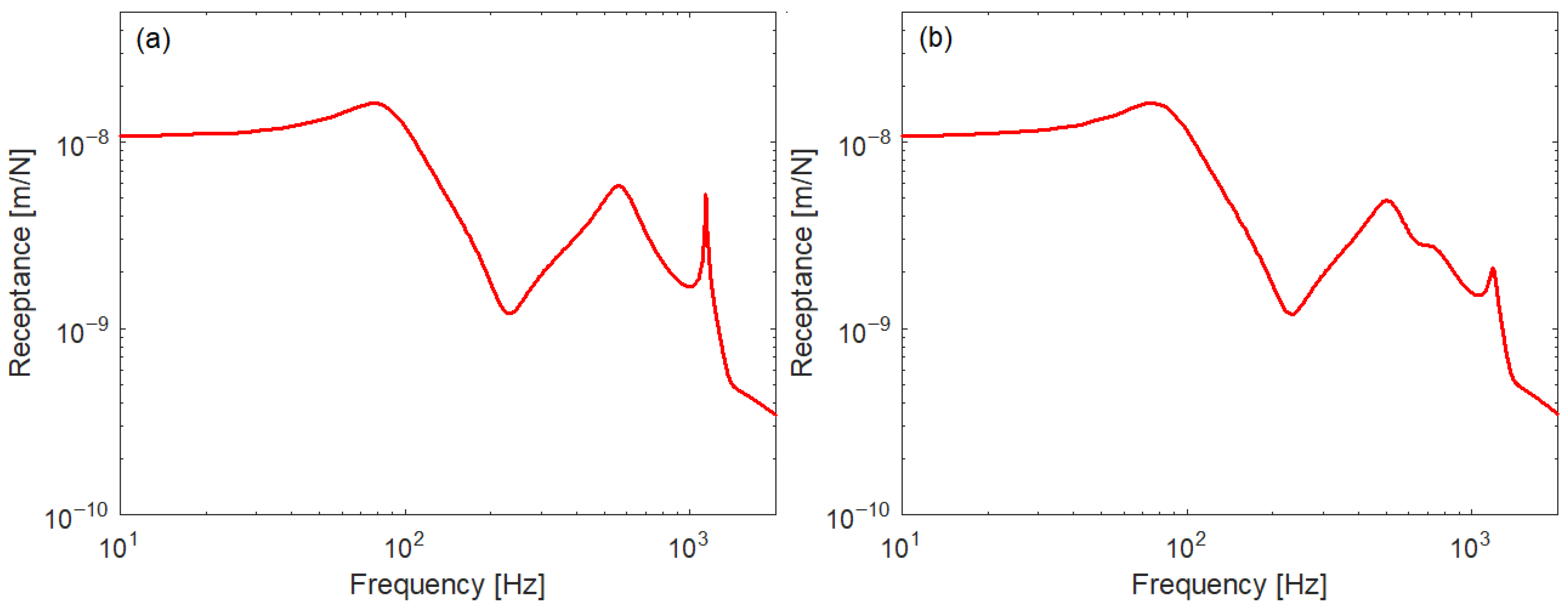
Figure 5 presents the frequency-domain Green function of the rail calculated using Equation (8) in the middle of the short sleeper bay (0.544 m), considering a stiff rail pad, for rail without and with rail dampers. The active section (where the harmonic force is applied) coincides with the passive section (calculation section) in both cases. The rail response shows two maxima in the receptance diagram, situated in the mid frequency range and separated by a minimum. These maxima correspond to the two resonance frequencies of the track, at 80 Hz and 550 Hz, while the minimum is explained by the dynamic absorber effect given by the sleepers, resulting in anti-resonance behaviour at 220 Hz. In this frequency range, the rail response resembles that of a two–mass oscillator. At higher frequencies, the dynamic behaviour of the rail changes due to the presence of discrete support: the so–called pinned–pinned resonance appears in this case at 1136 Hz when the sleeper bay equals half the wavelength of the rail (Figure 5a), but its amplitude is diminished in the presence of the rail dampers (Figure 5b).
Figure 6 shows the time-domain Green function calculated for −0.1 s ≤ t ≤ 0.1 s using Equation (12) applied to the two frequency-domain Green functions shown above. The values for t < 0 are significantly smaller than those for t > 0 and their contribution can therefore be neglected.
When the impulse force is applied (t = 0), the rail response increases rapidly to the highest value and then it is strongly damped. High-frequency oscillation persists in the case of the rail without rail dampers due to the pinned–pinned resonance. This oscillation becomes less visible due to the presence of the rail dampers. Overall, the rail response is weaker when it is equipped with rail dampers.
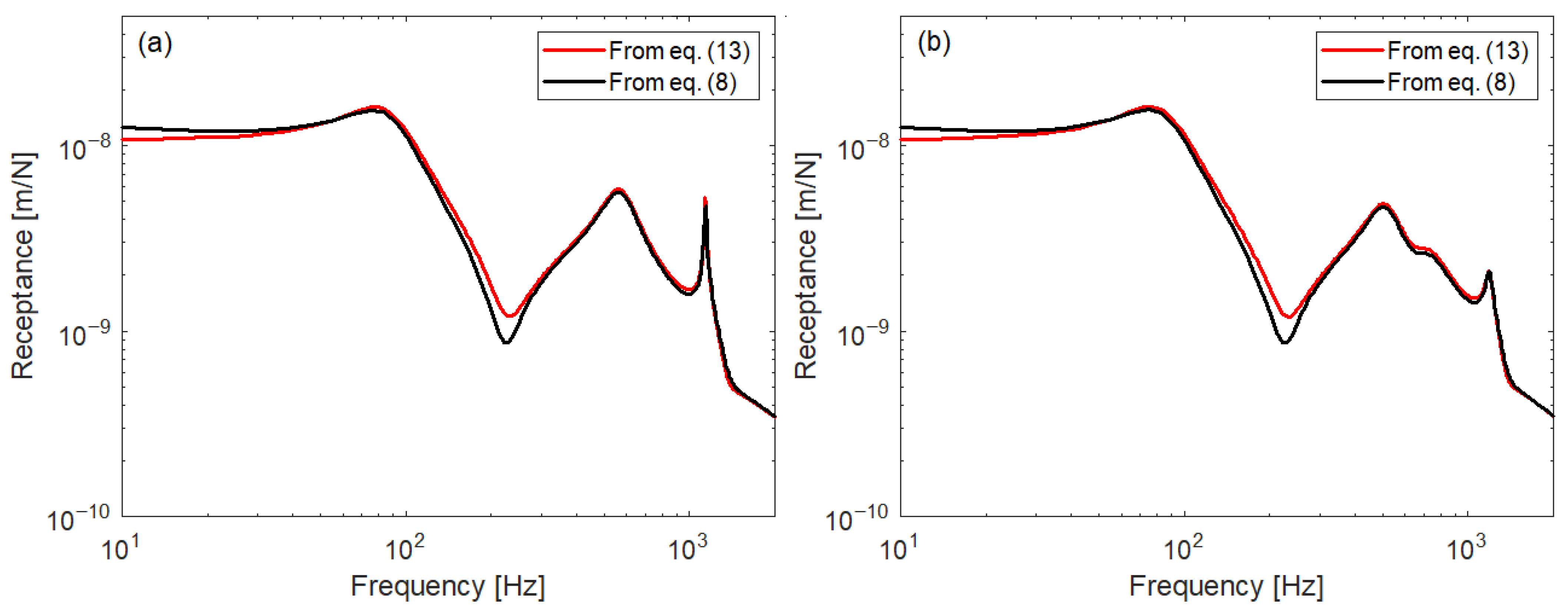
Figure 7 allows a comparison of the results obtained by applying the Equations (8) and (13). for the two cases considered here, rail without rail dampers and rail with rail dampers. Receptance calculated with Equation (13) is derived from the steady-state harmonic behaviour of the rail and therefore serves as a reference. Receptance calculated with Equation (8) comes from the time-domain Green function of the rail obtained using the hysteretic damping model. The two receptances are quite close, except for frequencies below 20 Hz and a narrow frequency range around the anti-resonance. These differences are less significant because the primary operating range of rail dampers covers the medium and high frequencies.

3.3. Wheel–Rail Steady-State Vibration

Steady-state wheel–rail vibration refers to the hypothetical vibration behaviour that would occur if the rolling surfaces of both the wheel and the rail are perfectly smooth and free of defect. This vibration is generated by parametric excitation due to the variation in rail stiffness at the point of wheel contact, resulting from the presence of sleepers.
The main characteristics of the steady-state wheel–rail vibration have been highlighted in Refs. [39,40,41,42], where the rail was modelled an infinite Timoshenko beam with a single type of one-mass oscillator representing the rail pad–semi–sleeper–ballast support. In the present study, the steady-state wheel–rail vibration is investigated using the same infinite Timoshenko beam model for the rail, but with an additional type of oscillator—a two–mass system—representing the rail damper with a hybrid damping mechanism.
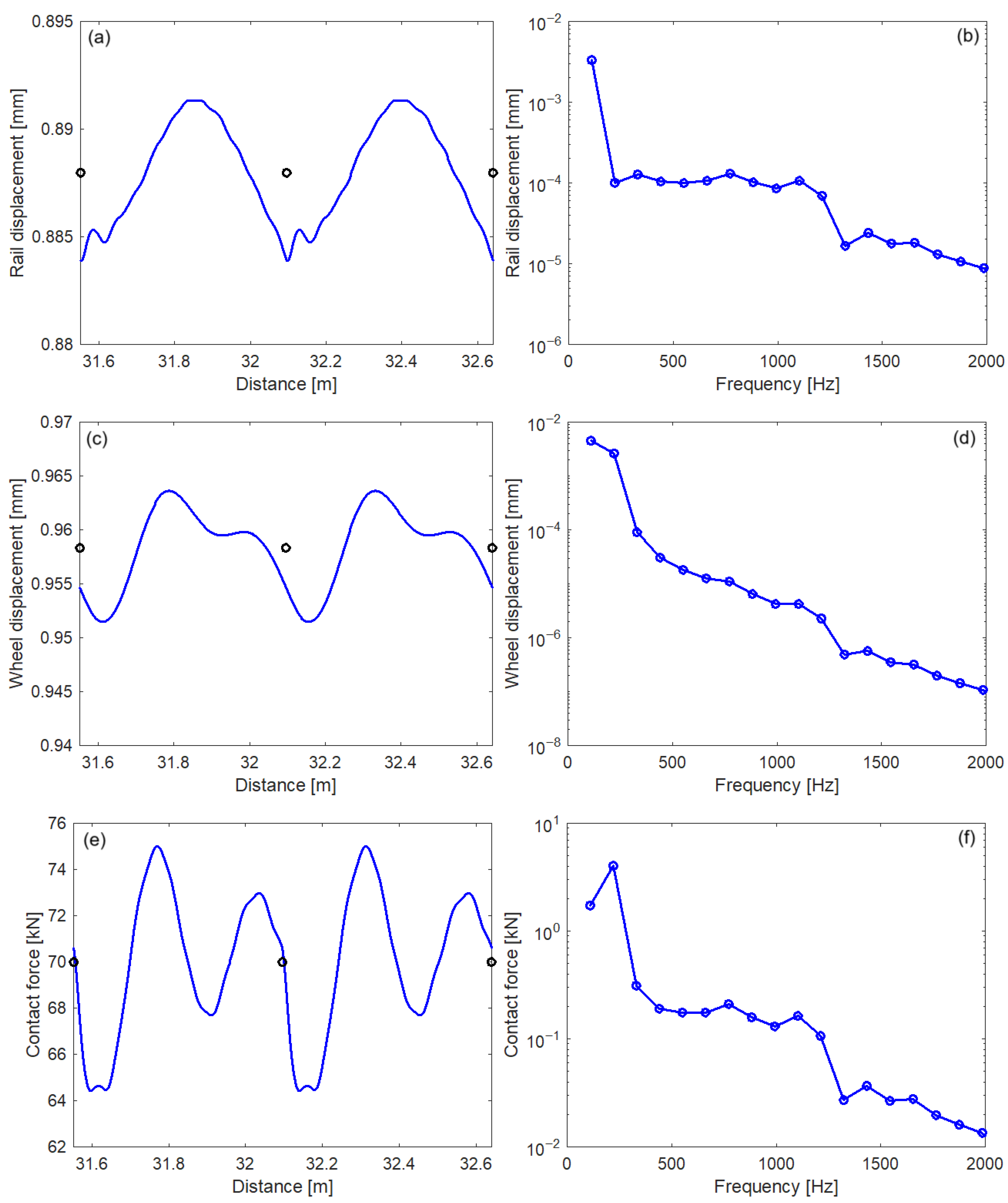
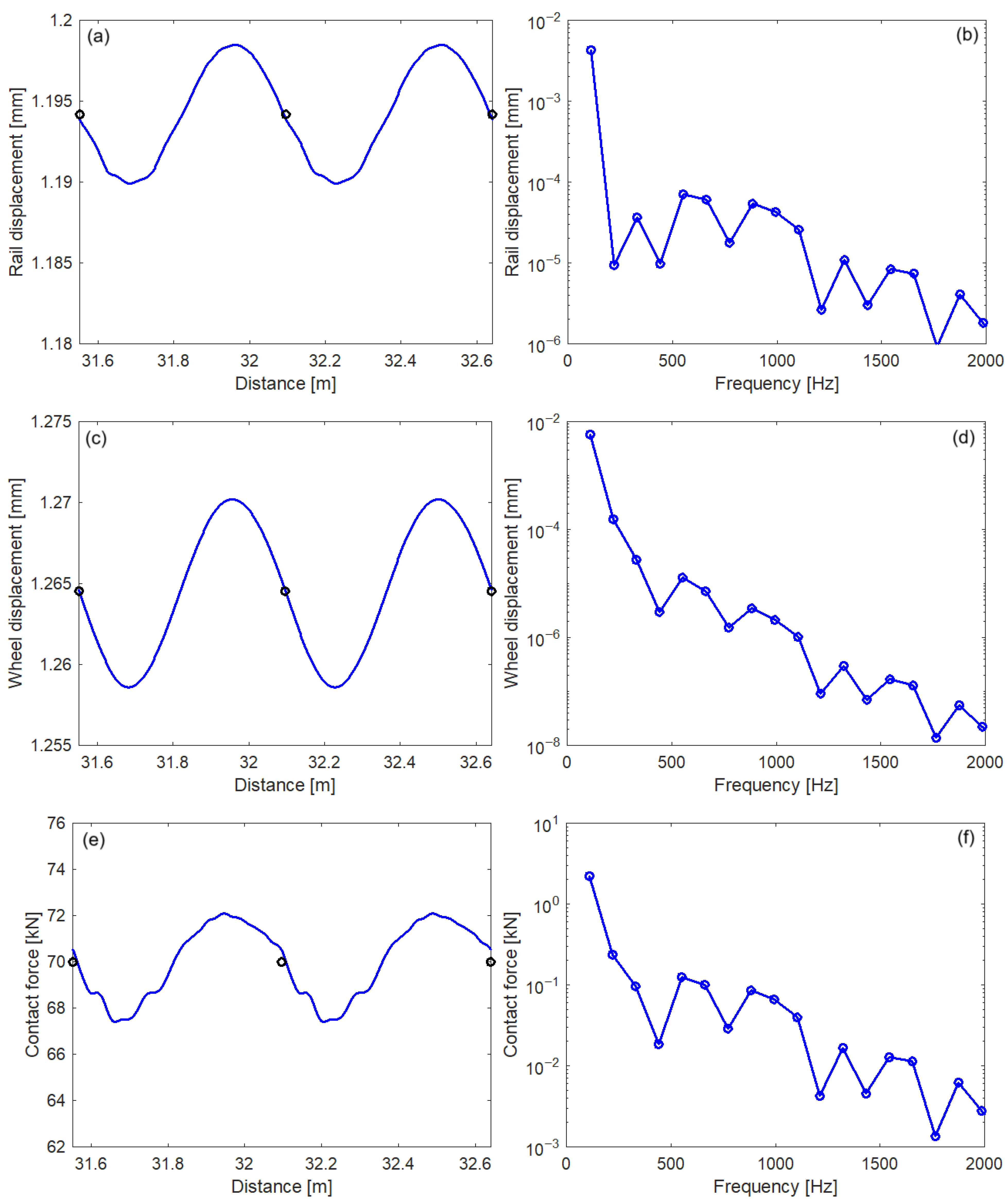
Figure 8 shows the wheel displacement and the rail displacement at the contact point, as well as the contact force along two sleeper bays, when the wheel runs at 60 m/s on a rail without rail dampers. The rail pad is stiff (kp = 300 MN/m) and the sleeper bay is short (l = 0.544 m).
The wheel–rail vibration is periodic, with its fundamental harmonic frequency equal to the ratio of the wheel speed to the distance between sleepers. In this case, the frequency of the fundamental harmonic is 110.3 Hz, and the frequencies of the higher harmonics form an arithmetic progression. The vibration at the contact point is dominated by the fundamental harmonic, which has a higher amplitude for the wheel (4.513 μm) than for the rail (3.343 μm). However, the harmonics of the rail spectrum exceed those of the wheel spectrum at frequencies above 300 Hz, because the wheel receptance is much lower than the rail’s receptance at the contact point. The contact force spectrum is dominated by the second harmonic, with an amplitude of 4.029 kN, compared to 1.734 kN for the first harmonic. This occurs because the frequency of the second harmonic practically coincides with the antiresonance frequency of the rail receptance (220 Hz), which increases the dynamic stiffness.
Figure 9 presents the same wheel–rail interaction parameters under conditions similar to those in Figure 8, except that the rail pads are soft in this case. The time series of the vibration parameters, especially for the wheel, are smoother owing to the higher elasticity of the rail pads. This indicates that higher-order harmonics have a reduced influence on the wheel–rail vibration steady state. Indeed, both the wheel and rail vibrations at the contact point are greatly reduced across the entire frequency spectrum compared to the previous case, when the rail pads were stiff. The same applies to the contact force. The fundamental harmonics of the spectra, however, are higher: 5.788 μm for the wheel, 4.297 μm for the rail at the contact point, and 2.224 kN for the contact force, because the antiresonance frequency of the rail in this case is around 137 Hz, close to the frequency of the fundamental harmonic.
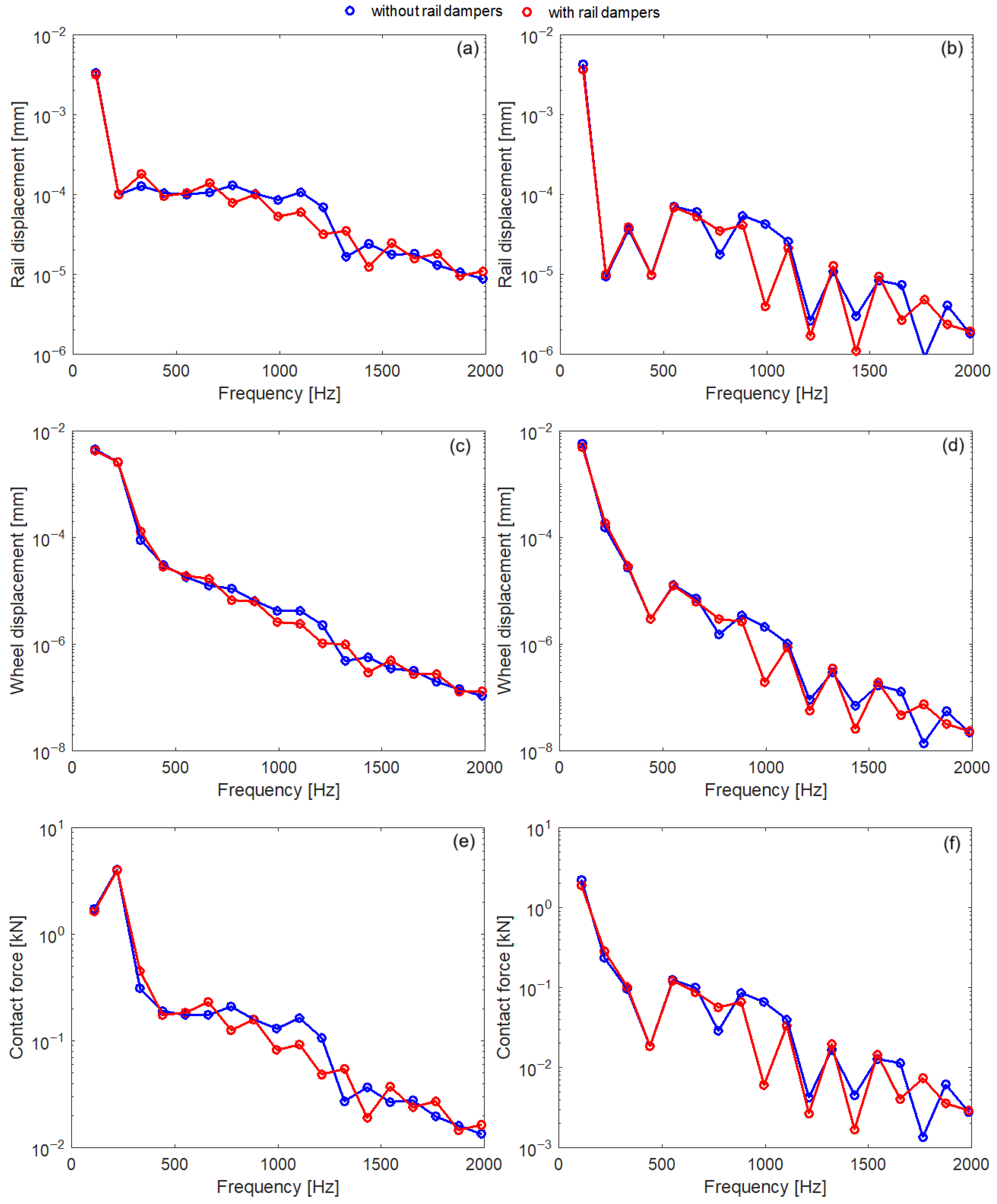
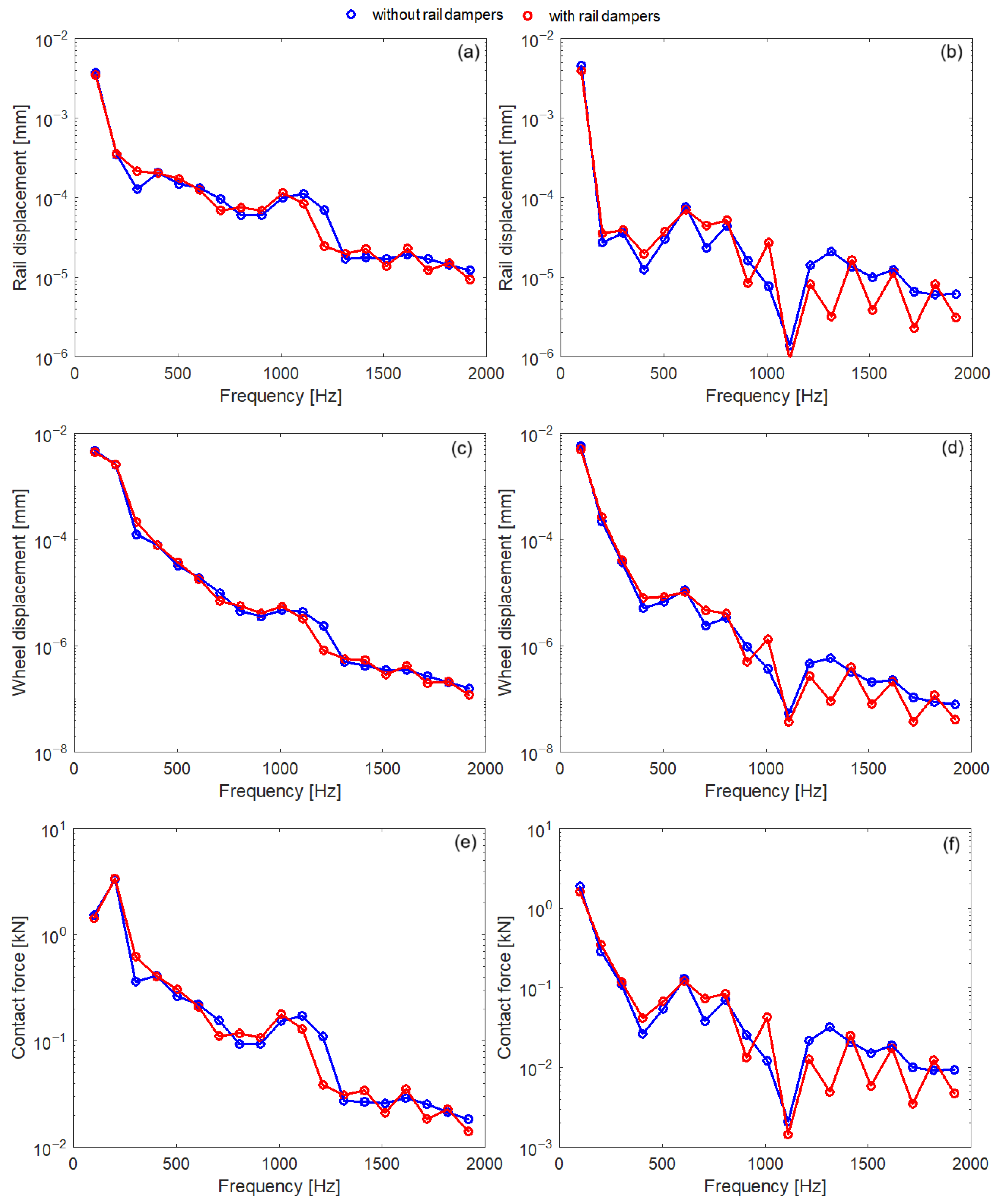
Figure 10 and Figure 11 present the influence of the rail dampers on the wheel–rail vibration steady state at 60 m/s, for stiff or soft rail pads and the sleeper bay of 544 mm (Figure 10) and 594 mm (Figure 11).
The rail dampers have opposite effects on the steady-state wheel–rail vibration: in certain frequency ranges, the vibration is reduced, while in others, it is intensified, depending on whether the rail pads are stiff or soft. For example, in Figure 10, the vibration is reduced by the rail dampers roughly in the range 700–1300 Hz for stiff rail pads and 850–1550 Hz for soft rail pads. At low frequencies, the effect of the rail dampers is minimal, as they are essentially inactive [36].
When the wheel runs at the same speed on a track with a larger sleeper bay (Figure 11, where the sleeper bay is 0.594 m), the fundamental harmonic frequency decreases to 60/0.594 = 101 Hz. In this case, the steady-state wheel–rail vibration is reduced by the use of the rail dampers in the frequency ranges of 600–800 Hz and 1000–1300 Hz for stiff rail pads. For soft rail pads, the effective frequency ranges shift to 800–900 Hz and 1100–1400 Hz.
Comparing the results from Figure 10 and Figure 11, we conclude that the rail dampers are more effective when the sleeper bay is shorter.
In all examined cases, the influence of using rail dampers is qualitatively similar for both wheel and rail displacements, as well as for the contact force.

3.4. Wheel–Rail Vibration Due to Random Roughness

In this section, the influence of rail dampers with a hybrid damping system on the vibration caused by the random roughness of the rolling surface is analysed using the model and method previously presented in the Section 2. Thus, starting from the synthesis of the running surface irregularities (Section 3.1), the wheel–rail motion equations are solved in the time domain to obtain the time series of the wheel and rail displacements at the contact point, as well as the contact force. Subsequently, the frequency spectra of these quantities of interest are analysed.
Previous studies have investigated the effect of rail dampers on reducing the wear of running surfaces using time-domain analysis methods [10,29,30,31] and on reducing rolling noise through frequency-domain analysis methods [9,14,16,19,20,21,22,23,24,25].
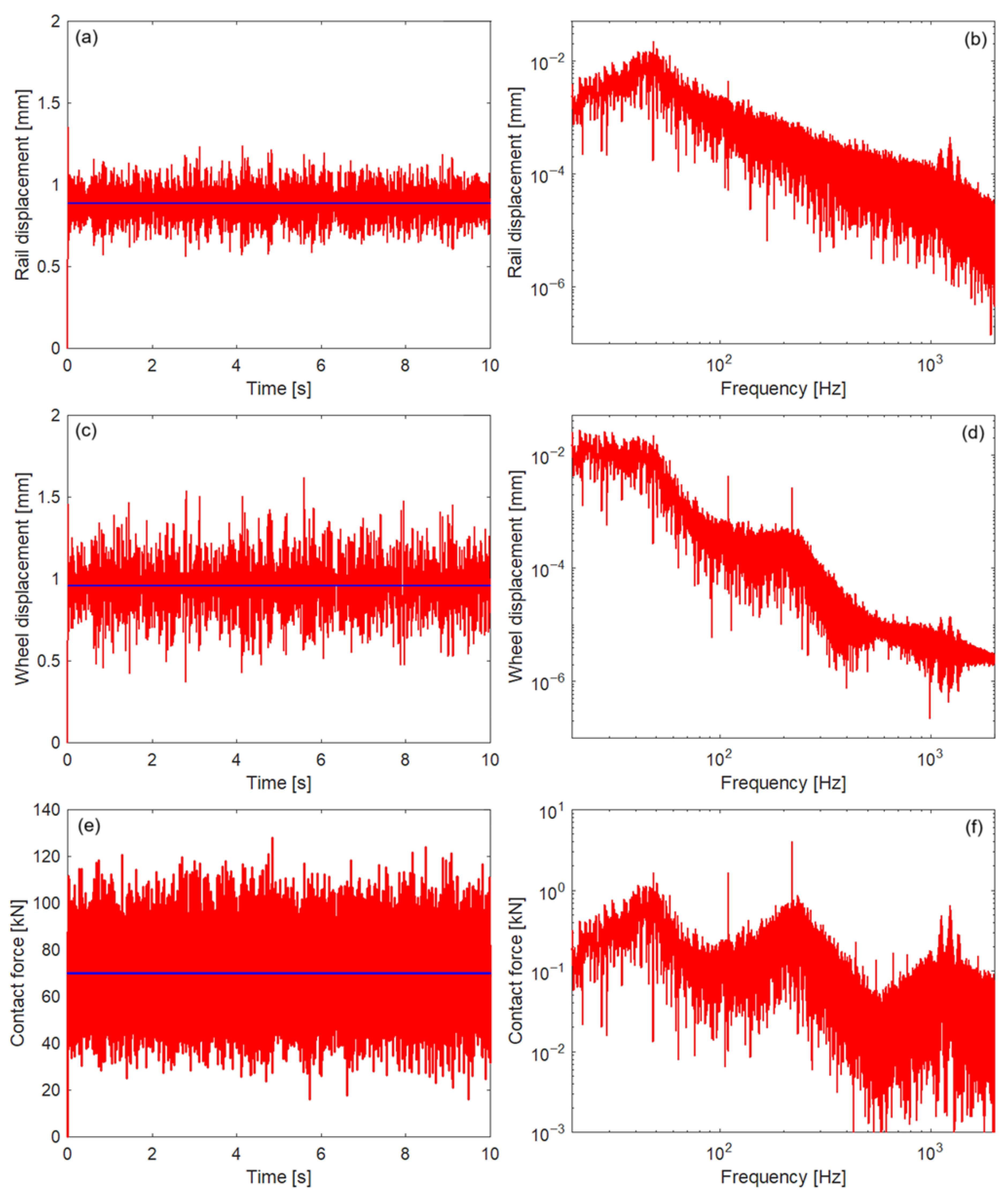
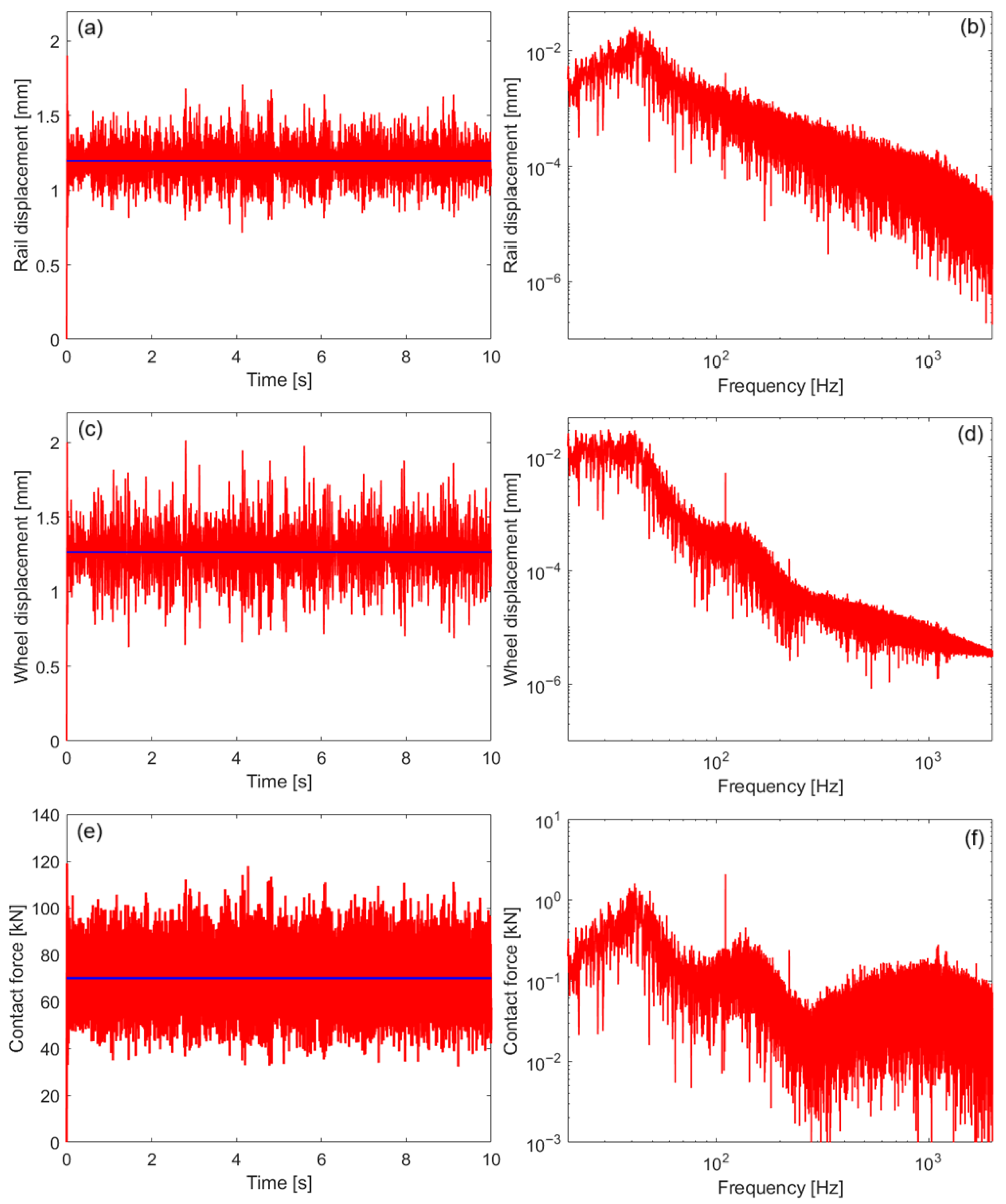
Figure 12 and Figure 13 show both the time series and the amplitude spectra of the wheel–rail displacement and contact force when the wheel runs at a speed of 60 m/s on a rail without dampers, with the rolling surfaces affected by the random roughness described in Figure 4. The sleeper bay is 0.544 m, and the rail pads are stiff in Figure 12 and soft in Figure 13.
The mean rail displacement is smaller than that of the wheel due to the elasticity of the wheel–rail contact. Thus, the mean rail displacement is 0.8878 mm and the mean wheel displacement is 0.95788 mm for stiff rail pads, and 1.1940 mm and 1.2642 mm for soft rail pads, respectively. At the same time, the mean wheel–rail displacement remains smaller in the case of stiff rail pads than in the case of soft rail pads, because the track structure is more rigid. In both simulations, the mean contact force equals the static load of 70 kN.
When the track is more flexible, being fitted with soft rail pads, both the wheel and the rail exhibit increased vibrations at the contact point, as shown by the effective displacement values. The effective wheel displacement is 195.38 μm with soft rail pads and 169.25 μm with stiff rail pads, while the effective rail displacement is 133.85 μm and 97.9 μm, respectively. Conversely, soft rail pads lead to a lower wheel–rail contact force, 10.36 kN compared to 13.39 kN for stiff rail pads.
The displacement spectra of both rail and wheel show a low-frequency peak associated with the wheel–rail resonance, occurring at approximately 45 Hz for stiff rail pads and 40 Hz for soft rail pads. Below this resonance, the wheel displacement dominates because the wheel behaves like an inertial body: its dynamic elasticity (receptance) increases as the frequency decreases, while the rail’s dynamic elasticity remains nearly constant. As a result, the wheel takes over to a greater extent the displacement imposed on the wheel–rail system by irregularities in the running surfaces. At frequencies above the wheel–rail resonance, the wheel’s dynamic elasticity decreases continuously, whereas the rail’s dynamic elasticity is dominated by two resonance peaks related to the track structure, which behaves similarly to a two-mass oscillator, as well as by the pinned–pinned resonance (see Figure 5a). In this frequency range, the dynamic elasticity of the rail prevails. Consequently, it is the rail that primarily absorbs the displacements imposed by surface irregularities. The continuous decay observed in both spectra is explained by the shape of the excitation spectrum generated by these surface irregularities (see Figure 4b).
The contact force spectrum exhibits an undulating profile with three prominent peaks separated by two minima. The peaks correspond to the wheel–rail system resonance, the dynamic absorber effect of the sleepers, and the pinned–pinned resonance mode, respectively. The two minima are associated with the natural resonance frequencies of the rail supported on the track (see Figure 5a). When the rail support is soft, the contact force at the wheel–rail resonance frequency increases due to the combined effect of the lower resonance frequency and amplified surface irregularities. The other two peaks exhibit reduced amplitudes due to the increased track elasticity from soft rail pads. At the same time, the peak corresponding to the dynamic absorber effect of the sleepers shifts to a lower frequency.
All amplitude spectra display a few harmonic components generated by the parametric excitation of the sleeper bay, which are especially noticeable in the spectrum of the wheel–rail contact force.
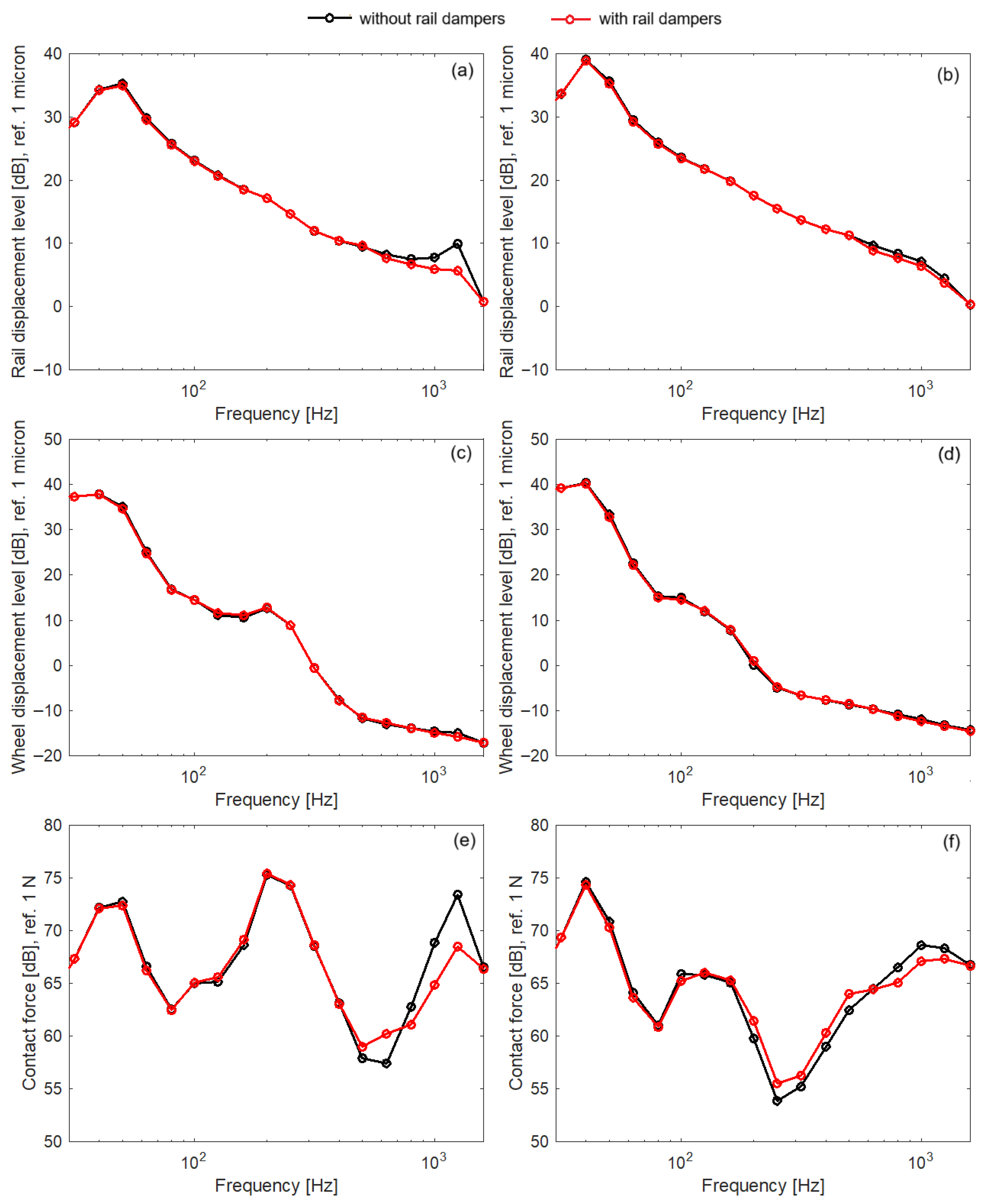
Figure 14 and Figure 15 illustrate the impact of rail dampers on the dynamic response of the wheel–rail system, expressed through the power spectra of rail displacement, wheel displacement, and contact force calculated at 60 m/s, for both soft and stiff rail pads. In both figures, the power spectra are shown in 1/3-octave bands within the 31.5–1600 Hz frequency range. Figure 14 corresponds to a short sleeper bay (0.544 m), while Figure 15 shows a longer sleeper bay (0.594 m).
The power spectra reproduce, in a ‘stylised’ form, the shape of the amplitude spectra presented and analysed earlier; therefore, this aspect is not discussed further.
Being mounted directly on the rail, dampers primarily affect rail vibration and the wheel–rail contact force across a broad frequency range—down to 500–600 Hz for stiff rail pads, 200–300 Hz for soft rail pads, and up to nearly 1600 Hz—while having minimal influence on the wheel’s motion. Therefore, the following analysis focuses on the influence of rail dampers on rail vibration and contact force.
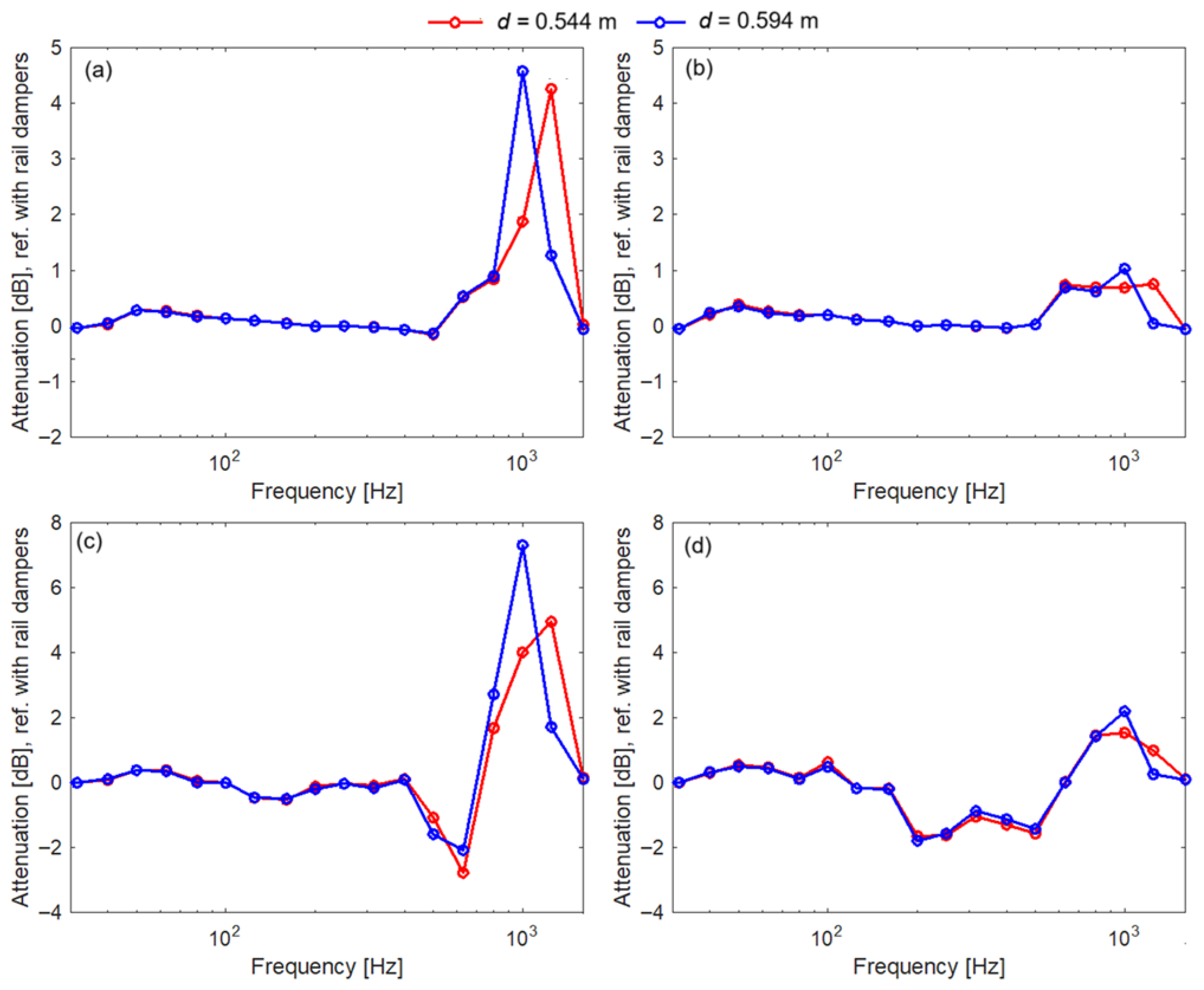
Figure 16 shows the attenuation in rail displacement and wheel–rail contact force levels due to the installation of rail dampers, calculated at 60 m/s for both stiff and soft rail pads, and for short and long sleeper bays. Taking as reference the rail displacement or contact force obtained for the rail with dampers, a positive attenuation value indicates a reduction in vibration, while a negative value indicates that vibration is amplified when the rail dampers are present according to the formula
A = 10 log 10 X w i t h o u t 2 X w i t h 2   dB .
Here, X2 denotes the mean square of the quantity of interest, and the subscripts without and with indicate whether the rail is not equipped or equipped with dampers, respectively.
When the sleeper spacing is 0.544 m and stiff rail pads are used, rail vibration levels are reduced by up to 4.258 dB in the 630–1600 Hz range, and the contact force levels by up to 4.956 dB in the 800–1600 Hz range. At the same time, the contact force level increases up to 2.772 dB at 500 and 630 Hz. For a longer sleeper spacing of 0.594 m with the same stiff rail pads, rail displacement levels are reduced by up to 4.579 dB in the 630–1250 Hz range, and the wheel–rail contact force by up to 7.310 dB in the 800–1250 Hz range. In this case as well, an increase in the contact force level of up to 2.072 dB is observed at 500 and 630 Hz.
With soft rail pads, the effect of the rail dampers is similar but noticeably weaker. For short sleeper spacing, the reduction in rail vibration levels reaches up to 0.755 dB in the 630–1250 Hz range, and the reduction in contact force level up to 1.539 dB in the same range. The contact force level may increase by up to 1.642 dB in the 200–500 Hz range. Slightly higher values are obtained for long sleeper spacing: rail displacement levels are reduced by up to 1.034 dB, the contact force level by up to 2.193 dB, while the increase reaches up to 1.791 dB.
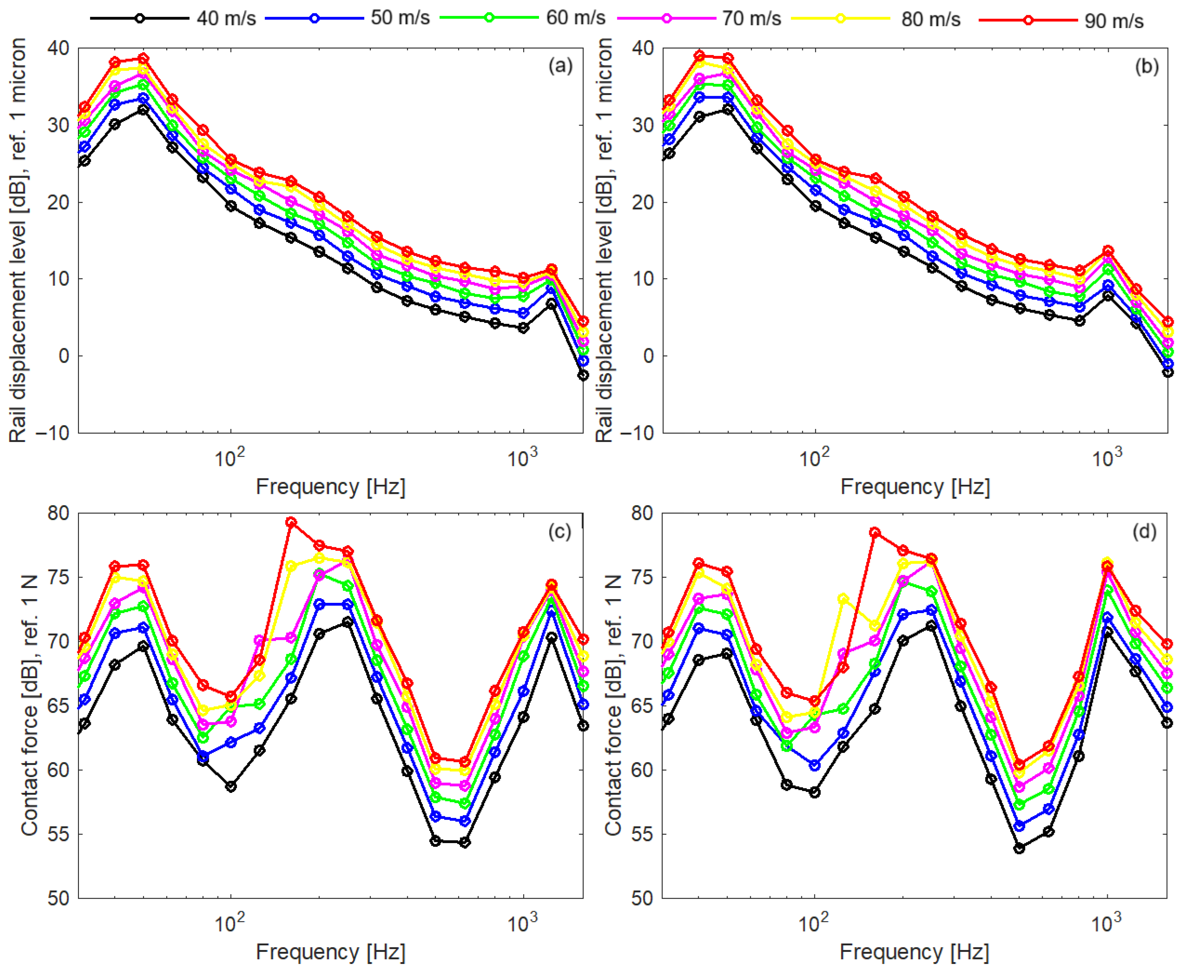
Speed is an essential parameter that influences the vibration of the wheel–rail system. Therefore, the following analysis investigates the performance of the rail damper with a hybrid damping system as a function of wheel speed, with the discussion limited to the case of stiff rail pads.
Figure 17 shows the impact of wheel speed on the dynamic response of the wheel–rail system, expressed through the power spectra of rail displacement and contact force. The spectra were calculated for wheel speeds ranging from 40 to 90 m/s, with an increment of 10 m/s. Overall, changing the wheel speed does not significantly affect the main frequency characteristics of the power spectra; their shape remains essentially unchanged. Two factors contribute to this outcome: (i) the rail receptance at the contact point is only weakly dependent on wheel speed, and (ii) the spectrum of running surface irregularities retains its shape as the wheel speed varies. Nevertheless, increasing the wheel speed amplifies the inertia forces of the wheel–rail system, leading to higher vibration levels.
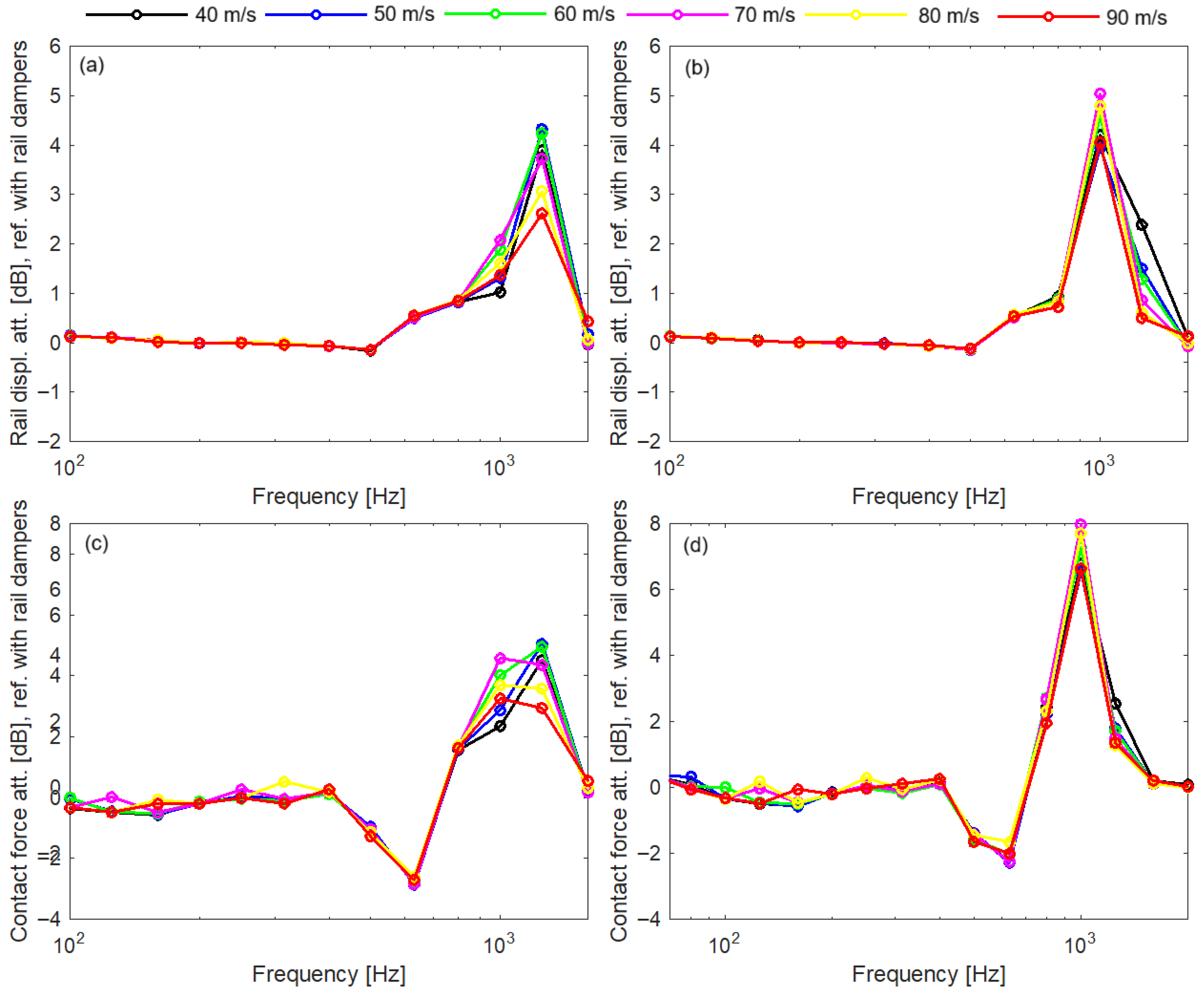
Figure 18 presents the attenuation in rail displacement and wheel–rail contact force levels due to the installation of rail dampers. The results are calculated for the same wheel speeds as in the previous analysis, for stiff rail pads, and for both short and long sleeper bays. The plotted frequency range is limited to 100–1600 Hz to provide a detailed view. Wheel speed does not significantly alter the spectra of rail displacement and contact force attenuation. The effectiveness of the dampers is most pronounced at the dominant pinned–pinned resonance frequencies and is more evident in the case of the long sleeper bay.
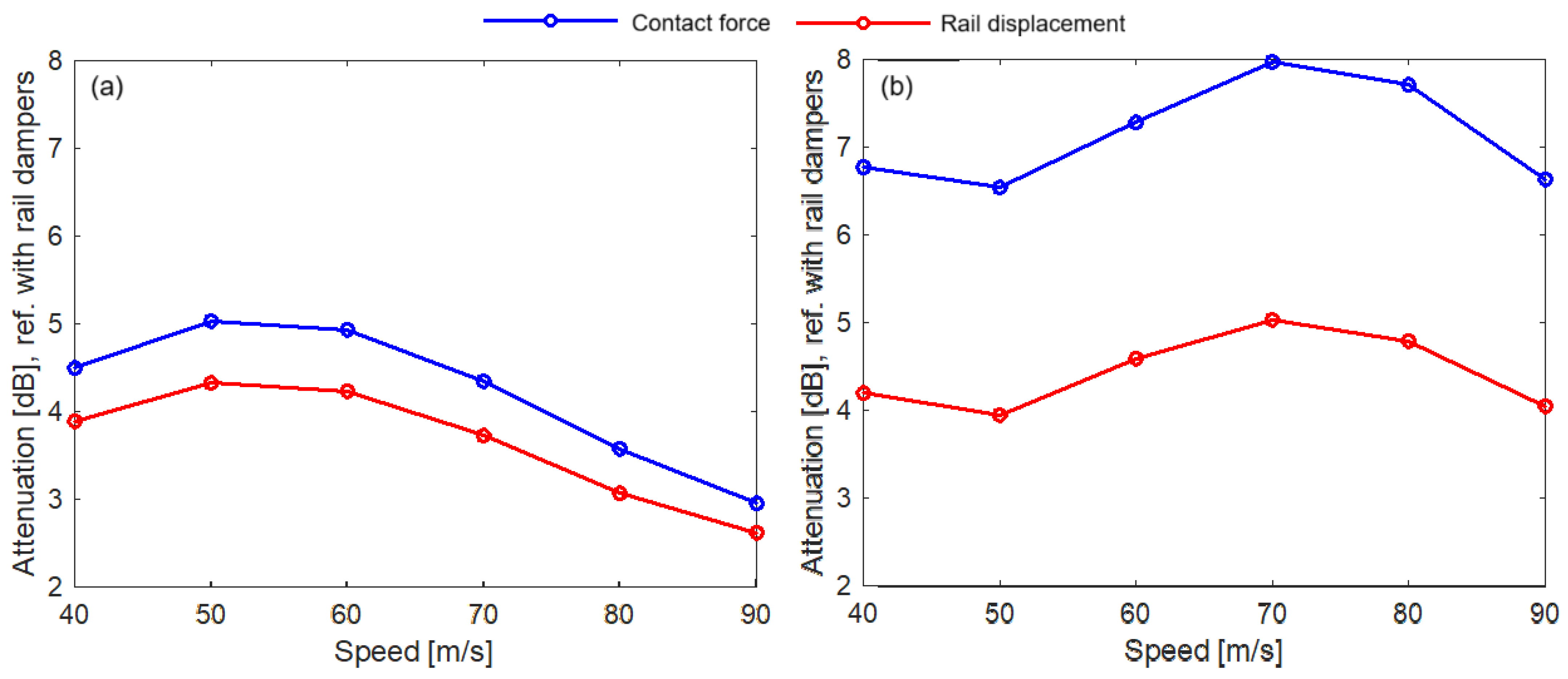
Figure 19 highlights, from the previously analysed data, the impact of wheel speed on rail displacement and contact force attenuation at the pinned–pinned resonance for each sleeper bay considered. When the sleeper bay is 0.544 m, the pinned–pinned resonance occurs near the 1/3 octave centred at 1250 Hz, while for the 0.595 m sleeper bay, it appears close to the 1/3 octave centred at 1000 Hz. Attenuation is consistently higher for the contact force than for rail displacement, regardless of sleeper spacing and wheel speed. For each configuration, there exists a wheel speed at which the rail damper effectiveness reaches its maximum: at 50 m/s for the 0.544 m spacing, with a contact force attenuation of 5.032 dB and rail displacement attenuation of 4.326 dB; and at 70 m/s for the 0.594 m spacing, with a contact force attenuation of 7.973 dB and rail displacement attenuation of 5.036 dB. In both cases, the effectiveness of the rail dampers decreases at higher wheel speeds.

4. Conclusions

This paper explores and analyses the vertical vibration of a loaded wheel running on a light rail equipped with rail dampers that use a mixed damping system, under the excitation of random roughness on the rolling surfaces, with the aim of assessing the effect of these rail dampers on the dynamic behaviour at the wheel–rail interface. In this theoretical approach, the rail is modelled as an infinite Timoshenko beam, which rests on equally spaced point-type supports that simulate the viscoelastic properties of the rail pad and ballast, as well as the inertia of the sleepers. The internal friction in rail, rail pads, and ballast is represented through hysteretic damping. The wheel is treated as a rigid body. The rail damper model consists of a two-mass oscillator attached to the rail at the mid–span.
The solution of the equations of motion is based on a heuristic application of the convolution theorem, aimed at obtaining a sufficiently accurate numerical approximation by exploiting the relationship between Green’s functions in the time and frequency domains, as mediated by the Fourier transform.
The numerical application focuses on the wheel–rail vibration in two regimes: the steady-state behaviour on ideally smooth surfaces, and the sustained vibration induced by surface irregularities, with stiff and soft rail pads, as well as short and long sleeper spacing.
The main conclusions are as follows:
(1)
Because rail dampers are attached directly to the rail, they primarily affect the rail dynamics and wheel–rail contact force over a relatively wide frequency range, starting at 500–600 Hz for stiff rail pads and 200–300 Hz for soft rail pads, and extending up to nearly 1600 Hz;
(2)
Rail dampers significantly reduce the level of rail vibration and the wheel–rail contact force when stiff rail pads are used;
(3)
With soft rail pads, the reduction in the vibration and contact force level is considerably lower;
(4)
The largest reduction in vibration level and contact force is observed with a long sleeper bay;
(5)
However, rail dampers slightly amplify the contact force at the lower edge of their effective frequency range;
(6)
Effectiveness of the rail dampers depends on wheel speed, reaching its maximum at a certain value and subsequently decreasing as the speed increases.
Future research will focus on evaluating the effect of rail dampers with mixed damping systems under other excitation mechanisms, such as wheel flats.

Author Contributions

Conceptualisation, T.M.; methodology, T.M. and M.-A.G.; software, T.M., D.F. and M.-A.G.; validation, T.M.; formal analysis, T.M., M.-A.G. and D.F.; investigation, T.M. and D.F.; resources, T.M., D.F. and M.-A.G.; data curation, D.F.; writing—original draft preparation, T.M.; writing—review and editing, T.M.; visualisation, D.F.; supervision, T.M. and M.-A.G.; project administration, T.M.; funding acquisition, M.-A.G. and T.M. All authors have read and agreed to the published version of the manuscript.

Funding

The first and the third authors declare that their work was supported by a grant from the National Program for Research of the National Association of Technical Universities—GNAC ARUT 2023, contract no. 154/04.12.2023.

Institutional Review Board Statement

Not applicable.

Informed Consent Statement

Not applicable.

Data Availability Statement

The raw data supporting the conclusions of this article will be made available by the authors on request.

Conflicts of Interest

The authors declare no conflicts of interest.

References

  1. Mazilu, T. Comfort at the Rolling Stock; Matrixrom: Bucharest, Romania, 2003. (In Romanian) [Google Scholar]
  2. Hemsworth, B. Environmental Noise Directive Development of Action Plans for Railways, Prepared for International Union of Railways. 2008. Available online: https://uic.org/IMG/pdf/action_planning_paper_final-2.pdf (accessed on 16 October 2024).
  3. Thompson, D. Railway Noise and Vibration: Mechanisms, Modelling and Means of Control, 2nd ed.; Elsevier Ltd.: London, UK, 2024. [Google Scholar]
  4. Mazilu, T. Vibrations; Matrixrom: Bucharest, Romania, 2012. (In Romanian) [Google Scholar]
  5. Wang, Y.; Dimitrovová, Z.; Yau, J.D. Laboratory Vibration Studies of Metro Tracks Equipped with Tuned Rail Dampers. J. Vib. Eng. Technol. 2023, 11, 2659–2669. [Google Scholar] [CrossRef]
  6. Chen, J.; Liu, W.; Sun, X. Effects of Tuned Rail Damper on Track Dynamic Characteristics Optimization. Procedia Eng. 2017, 199, 1616–1622. [Google Scholar] [CrossRef]
  7. Merideno, I.; Nieto, J.; Gil-Negrete, N.; Ortiz, J.G.G.; Landaberea, A.; Iartza, J. Theoretical prediction of the damping of a railway wheel with sandwich–type dampers. J. Sound Vib. 2014, 333, 4897–4911. [Google Scholar] [CrossRef]
  8. Peng, Y.; Zhang, D.; Sheng, X.; Thompson, D. A fundamental study on the performance of tuned mass dampers installed periodically on a fast-rotating train wheel. J. Sound Vib. 2024, 576, 118271. [Google Scholar] [CrossRef]
  9. Thompson, D.J.; Jones, C.J.C.; Waters, T.P.; Farrington, D. A tuned damping device for reducing noise from railway track. Appl. Acoust. 2007, 68, 43–57. [Google Scholar] [CrossRef]
  10. Wu, T.X. Effects on short pitch rail corrugation growth of a rail vibration absorber/damper. Wear 2011, 271, 339–348. [Google Scholar] [CrossRef]
  11. Mazilu, T.; Fologea, D. Experimental study on the performance of a rail damper. IOP Conf. Ser. Mater. Sci. Eng. 2018, 400, 620186. [Google Scholar] [CrossRef]
  12. Michalczyk, R.; Brzeziński, K.; Zbiciak, A. Numerical Vibration Response of Railway Track Retrofitted with Single Degree of Freedom Rail Dampers. IOP Conf. Ser. Mater. Sci. Eng. 2019, 661, 2–8. [Google Scholar] [CrossRef]
  13. Maes, J.; Sol, H. A double tuned rail damper—Increased damping at the two first pinned–pinned frequencies. J. Sound Vib. 2003, 267, 721–737. [Google Scholar] [CrossRef]
  14. Liu, H.P.; Wu, T.X.; Li, Z.G. Theoretical modelling and effectiveness study of rail vibration absorber for noise control. J. Sound Vib. 2009, 323, 594–608. [Google Scholar] [CrossRef]
  15. Dumitriu, M.; Cruceanu, I.C. On the Rolling Noise Reduction by Using the Rail Damper. J. Eng. Sci. Technol. Rev. 2017, 10, 87–95. [Google Scholar] [CrossRef]
  16. Jones, C.J.C.; Thompson, D.J.; Diehl, R.J. The use of decay rates to analyse the performance of railway track in rolling noise generation. J. Sound Vib. 2006, 293, 485–495. [Google Scholar] [CrossRef]
  17. Ryue, J.; Thompson, D.J.; White, P.R.; Thompson, D.R. Decay rate of propagating waves in railway tracks at high frequencies. J. Sound Vib. 2009, 320, 955–976. [Google Scholar] [CrossRef]
  18. EN ISO 3095:2013; Acoustics—Railway Applications—Measurement of Noise Emitted by Railbound Vehicles. British Standards Institution: London, UK, 2013.
  19. Wu, T.X. On the railway track dynamics with rail vibration absorber for noise reduction. J. Sound Vib. 2008, 309, 739–755. [Google Scholar] [CrossRef]
  20. Poisson, F.; Margiocchi, F. The use of dynamic on the rail to reduce the noise of steel railway bridges. J. Sound Vib. 2006, 293, 944–952. [Google Scholar] [CrossRef]
  21. Wu, T.X. Attenuating Railway Track Vibration by Rail Absorber for Noise Reduction. Noise Vib. Worldw. 2008, 39, 14–23. [Google Scholar] [CrossRef]
  22. Wu, T.X.; Liu, H.P. Reducing the rail component of rolling noise by vibration absorber: Theoretical prediction. Proc. IMechE Part F J. Rail Rapid Transit 2009, 223, 473–483. [Google Scholar] [CrossRef]
  23. Li, W.; Wang, A.; Gao, X.; Ju, L.; Liu, L. Development of multi-band tuned rail damper for rail vibration control. Appl. Acoust. 2021, 184, 108370. [Google Scholar] [CrossRef]
  24. Liu, H.; Wu, T.X. The influences on railway rolling noise of a rail vibration absorber and wave reflections due to multiple wheels. Proc. IMechE Part F J. Rail Rapid Transit 2010, 224, 227–235. [Google Scholar] [CrossRef]
  25. Liu, H.; Yang, J.; Wu, T. The influences of rail vibration absorber on normal wheel–rail contact forces due to multiple wheels. J. Vib. Control 2015, 21, 275–284. [Google Scholar] [CrossRef]
  26. Parker, A.; Weber, C. Rail Dampers—The First Australian Field Trial. In Proceedings of the 20th International Congress on Acoustics, ICA 2010, Sydney, Australia, 23–27 August 2010. [Google Scholar]
  27. Squicciarini, G.; Toward, M.G.R.; Thompson, D.J. Experimental procedures for testing the performance of rail dampers. J. Sound Vib. 2015, 359, 21–39. [Google Scholar] [CrossRef]
  28. Sun, F.; Sun, Z.; Liang, R.; Ding, D.; Ma, M. Experimental Study on the Rail Damper for Vibration and Noise Control and Rail Corrugation Suppression. Urban Rail Transit 2025, 11, 207–220. [Google Scholar] [CrossRef]
  29. Qian, W.J.; Huang, Z.Q.; Ouyang, H.; Chen, G.X.; Yang, H.J. Numerical investigation of the effects of rail vibration absorbers on wear behaviour of rail surface. Proc. IMechE Part J J. Eng. Tribol. 2018, 233, 424–438. [Google Scholar] [CrossRef]
  30. Qian, W.J.; Wu, Y.F.; Chen, G.X.; Ouyang, H. Experimental and numerical studies of the effects of a rail vibration absorber on suppressing short pitch rail corrugation. J. Vibroeng. 2016, 18, 1133–1144. [Google Scholar] [CrossRef]
  31. Croft, B.E.; Jones, C.J.C.; Thompson, D.J. Modelling the effect of rail dampers on wheel–rail interaction forces and rail roughness growth rates. J. Sound Vib. 2009, 323, 17–32. [Google Scholar] [CrossRef]
  32. EN 13674-1:2003; Railway Applications—Track—Rail Part 1: Vignole Railway Rails 46 kg/m and Above. British Standards Institution: London, UK, 2003.
  33. Fologea, D.; Mazilu, T.; Gheți, M.A.; Apostol, I.I. Parametric Study on the Effect of Rail Dampers on Track Decay Rate. Appl. Sci. 2024, 14, 9541. [Google Scholar] [CrossRef]
  34. Maia, N. Reflections on the hysteretic damping model. Shock Vibr. 2009, 16, 529–542. [Google Scholar] [CrossRef]
  35. Macris, N. Causal hysteretic element. J. Eng. Mech. 1997, 123, 1209–1214. [Google Scholar] [CrossRef]
  36. Mazilu, T. Green’s functions for analysis of dynamic response of wheel/rail to vertical excitation. J. Sound Vib. 2007, 306, 31–58. [Google Scholar] [CrossRef]
  37. Cruceanu, I.C. Research on Wheel–Rail System Vibrations. Doctoral Thesis, University Politehnica of Bucharest, Bucharest, Romania, 2021. (In Romanian). [Google Scholar]
  38. EN ISO 3381:2011; Railway Applications—Acoustics—Measurement of Noise Inside Railbound Vehicles. British Standards Institution: London, UK, 2011.
  39. Wu, T.X.; Thompson, D.J. On the parametric excitation of the wheel/track system. J. Sound Vib. 2004, 278, 725–747. [Google Scholar] [CrossRef]
  40. Wu, T.X. Parametric excitation of wheel/track system and its effects on rail corrugation. Wear 2008, 265, 1176–1182. [Google Scholar] [CrossRef]
  41. Mazilu, T. Wheel\Rail Interaction Due to Parametric Excitation. U.P.B. Sci. Bull. Ser. D 2007, 69, 23–38. [Google Scholar]
  42. Abe, K. Rail model for parametric excitation analysis of a discretely supported track. J. Sound Vib. 2025, 618, 119309. [Google Scholar] [CrossRef]
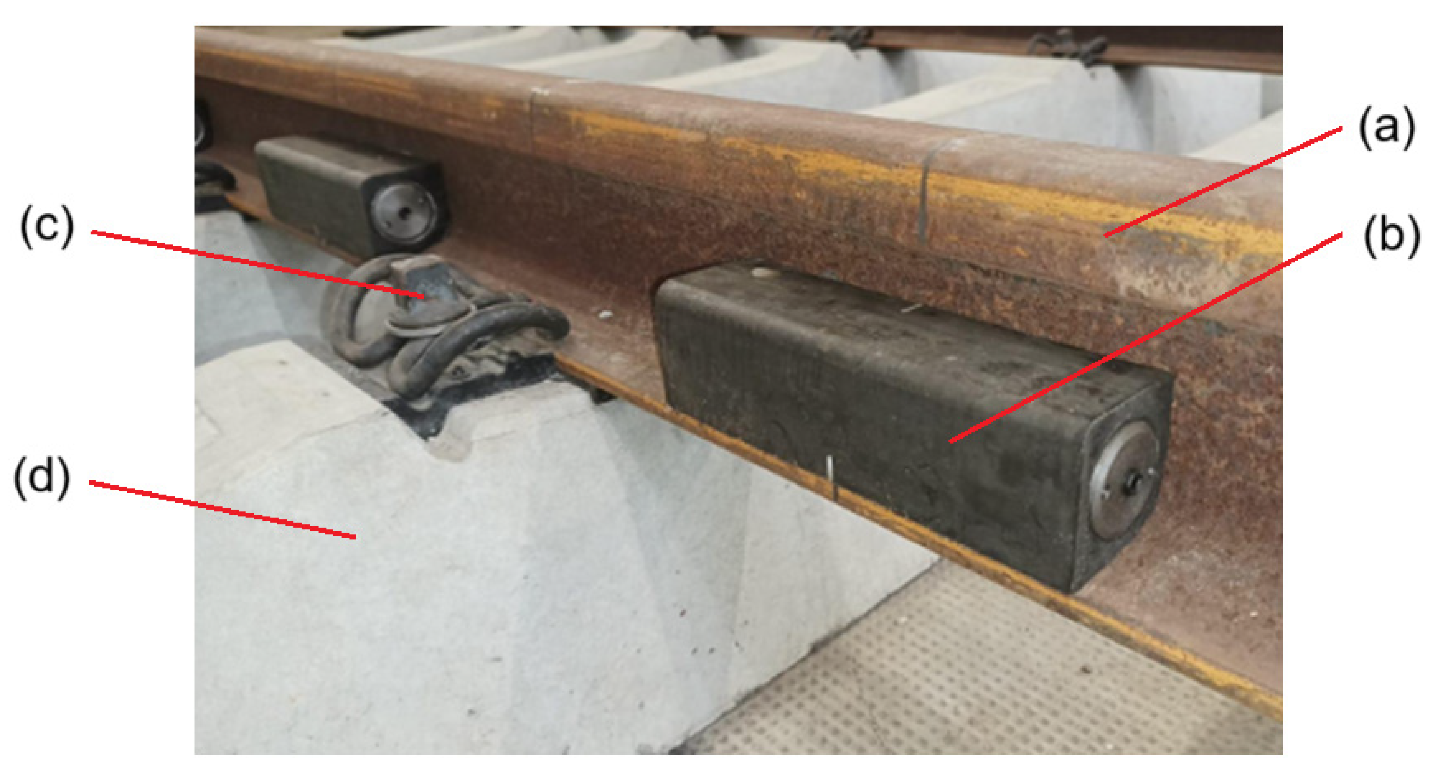
Figure 1. Rail dampers with mixed damping system: (a) 49E1 rail; (b) rail damper; (c) fastener; (d) sleeper.
Applsci 15 10027 g001
Figure 2. Model of a moving wheel and rail with rail dampers: (a) wheel; (b) rail; (c) wheel–rail contact; (d) rail pad; (e) semi–sleeper; (f) ballast; (g–j) components of the rail damper: (g) primary elastic element; (h) primary mass; (i) secondary elastic element; (j) secondary mass.
Applsci 15 10027 g002
Figure 3. Roughness spectra: (a) roughness PSD; (b) roughness level.
Applsci 15 10027 g003
Figure 4. Pseudo-random roughness: (a) roughness profile; (b) roughness spectrum at 60 m/s.
Applsci 15 10027 g004
Figure 5. Rail receptance at middle span for stiff rail pad and sleeper bay of 0.544 m: (a) without rail dampers; (b) with rail dampers.
Applsci 15 10027 g005
Figure 6. Time-domain Green function calculated at middle span for stiff rail pad and sleeper bay of 0.544 m: (a) without rail dampers; (b) with rail dampers.
Applsci 15 10027 g006
Figure 7. Rail receptance calculated with Equations (8) and (13) at middle span for stiff rail pad and sleeper bay of 0.544 m: (a) without rail dampers; (b) with rail dampers.
Applsci 15 10027 g007
Figure 8. Wheel–rail vibration steady–state at 60 m/s for stiff rail pad and sleeper bay of 0.544 m—rail without rail dampers: (a) rail displacement; (b) rail displacement spectrum; (c) wheel displacement; (d) wheel displacement spectrum; (e) contact force; (f) contact force spectrum; (a,c,e) , sleeper position.
Applsci 15 10027 g008
Figure 9. Wheel–rail vibration steady state at 60 m/s for soft rail pad and sleeper bay of 0.544 m—rail without rail dampers: (a) rail displacement; (b) rail displacement spectrum; (c) wheel displacement; (d) wheel displacement spectrum; (e) contact force; (f) contact force spectrum; (a,c,e) , sleeper position.
Applsci 15 10027 g009
Figure 10. Wheel–rail vibration steady state at 60 m/s and sleeper bay of 0.544 m, comparison without/with rail dampers: (a,c,e) stiff rail pad; (b,d,f) soft rail pad; (a,b) rail displacement; (c,d) wheel displacement; (e,f) contact force.
Applsci 15 10027 g010
Figure 11. Wheel–rail vibration steady state at 60 m/s and sleeper bay of 0.594 m, comparison without/with rail dampers: (a,c,e) stiff rail pad; (b,d,f) soft rail pad; (a,b) rail displacement; (c,d) wheel displacement; (e,f) contact force.
Applsci 15 10027 g011
Figure 12. Wheel–rail vibration due to random roughness at 60 m/s for stiff rail pad and sleeper bay of 0.544 m—rail without rail dampers: (a) rail displacement; (b) wheel displacement; (c) contact force; (d) rail displacement spectrum; (e) wheel displacement spectrum; (f) contact force spectrum.
Applsci 15 10027 g012
Figure 13. Wheel–rail vibration due to random roughness at 60 m/s for soft rail pad and sleeper bay of 0.544 m—rail without rail dampers: (a) rail displacement; (b) wheel displacement; (c) contact force; (d) rail displacement spectrum; (e) wheel displacement spectrum; (f) contact force spectrum.
Applsci 15 10027 g013
Figure 14. Wheel–rail vibration due to random roughness at 60 m/s and sleeper bay of 0.544 m, comparison without/with rail dampers: (a,c,e) stiff rail pad; (b,d,f) soft rail pad; (a,b) rail displacement; (c,d) wheel displacement; (e,f) contact force.
Applsci 15 10027 g014
Figure 15. Wheel–rail vibration due to random roughness at 60 m/s and sleeper bay of 0.594 m, comparison without/with rail dampers: (a,c,e) stiff rail pad; (b,d,f) soft rail pad; (a,b) rail displacement; (c,d) wheel displacement; (e,f) contact force.
Applsci 15 10027 g015
Figure 16. Attenuation due to the rail dampers at 60 m/s: (a) rail displacement, stiff rail pads; (b) rail displacement, soft rail pads; (c) contact force, stiff rail pads; (d) contact force, soft rail pads.
Applsci 15 10027 g016
Figure 17. Rail displacement and contact force for stiff rail pads and different wheel speeds: (a,c) sleeper bay 0.544 m; (b,d) sleeper bay 0.594 m.
Applsci 15 10027 g017
Figure 18. Attenuation due to the rail dampers for stiff rail pads at different wheel speeds: (a,c) sleeper bay 0.544 m; (b,d) sleeper bay 0.594.
Applsci 15 10027 g018
Figure 19. Rail displacement and contact force attenuation for stiff rail pads at different wheel speeds: (a) sleeper bay 0.544 m, 1250 Hz; (b) sleeper bay 0.594 m, 1000 Hz.
Applsci 15 10027 g019
Table 1. Parameters of the wheel–rail with rail dampers model.
ParameterNotationValue
Wheel massMw800 kg
Hertzian constantCH118.6 GN/m3/2
Static load Qo70 kN
Rail mass per unit lengthm49.4 kg/m
Rail densityr7850 kg/m3
Young’s modulus of elasticity E210 GPa
Shear modulus of elasticity G81 GPa
Rail loss factorη0.01
Cross-section areaS62.92 × 10−4 m2
Area moment of inertiaI18.16 × 10−6 m4
Shear coefficientκ0.40
Sleeper mass (half)Mt131 kg
Rail pad stiffness kpSoft60 MN/m
Stiff300 MN/m
Rail pad loss factorηp0.30
Ballast stiffnesskb40 MN/m
Ballast loss factorηb0.60
Sleeper baylShort 0.544 m
Long 0.595 m
First body mass M13.650 kg
Second body mass M23.514 kg
First elastic element stiffness k150.62 MN/m
First elastic element loss factorη10.35
Second elastic element stiffnessk25.617 MN/m
Second elastic element loss factorη20.25
Coefficient of roughness PSD Kr6.04 × 10−8 m0.18rad1.82
Contant of roughness PSD Ωo3.1 × 10−8 rad2.82/m0.82
Exponent of roughness PSDn3.82
Minimum value of the wavenumber rangeΩmin1.777 rad/m
Maximum value of the wavenumber rangeΩmax352.988 rad/m
Wavenumber-domain discretization step 0.001 rad/m
Time-domain discretization stepDt2/60 ms
Disclaimer/Publisher’s Note: The statements, opinions and data contained in all publications are solely those of the individual author(s) and contributor(s) and not of MDPI and/or the editor(s). MDPI and/or the editor(s) disclaim responsibility for any injury to people or property resulting from any ideas, methods, instructions or products referred to in the content.