Article

Design of a Compact IPT System for Medium Distance-to-Diameter Ratio AGV Applications with Enhanced Misalignment Tolerance

1
Department of Electrical Engineering, Chonnam National University, 77 Yongbong-ro, Buk-gu, Gwangju 61186, Republic of Korea
2
Zhengzhou Research Institute, Harbin Institute of Technology, Zhengzhou 450000, China
*
Author to whom correspondence should be addressed.
Appl. Sci. 2025, 15(17), 9799; https://doi.org/10.3390/app15179799
Submission received: 8 August 2025 / Revised: 1 September 2025 / Accepted: 4 September 2025 / Published: 6 September 2025
(This article belongs to the Special Issue Control Systems for Next Generation Electric Applications)

Abstract

Automated guided vehicles (AGVs) operating in uneven environments are typically designed with an elevated chassis to enhance obstacle-crossing. In inductive power transfer (IPT) systems for such AGVs, a long transmission distance along with limited installation space for coils leads to a medium distance-to-diameter ratio (DDR) (1 < DDR ≤ 2), which reduces coupling efficiency and degrades misalignment tolerance. To address this issue, this paper proposes a compact dual-receiver IPT system for medium DDR conditions. The system adopts a flat U-shaped solenoid (FUS) coil as both the transmitter and the primary receiver, and a square solenoid (SS) coil as the secondary receiver, forming the FUSS dual-receiver structure. The FUS coil is optimized through finite element analysis to improve coupling, while the SS coil captures vertical flux to compensate for misalignment losses, thereby enhancing misalignment tolerance. A hybrid rectifier integrating a full-bridge and voltage doubler topology is used to suppress output voltage fluctuation, reduce the number of receiver coil turns, and minimize system volume. A 300 W/100 kHz prototype with a coupler size of 183 × 126 × 838 mm3 achieves 83.51% efficiency under medium DDR and a 185 mm air gap. Voltage fluctuation remains within 5% under ±51.4% X-axis and ±51.7% Y-axis misalignment, confirming the stable power delivery and improved misalignment tolerance of the system.

1. Introduction

Inductive power transfer (IPT) is a contactless, safe, and convenient power delivery method that has attracted widespread attention in recent years [1,2,3]. It is particularly well suited for applications in consumer electronics [4,5,6], transportation systems [7,8,9], and medical devices, where plug-in connectors are impractical or contactless operation is preferred. Among these, automated guided vehicles (AGVs) represent a prominent use case. With the growing deployment of AGVs in smart factories, mission-critical scenarios such as disaster rescue and military operations, the demand for fully automated, human-free charging solutions continues to increase. However, in uneven environments, AGVs are often equipped with elevated chassis to improve obstacle-crossing and terrain adaptability. This increases the transmission distance between the transmitter and receiver coils, weakening the magnetic coupling strength, reducing the coupling coefficient, and lowering the power transfer efficiency. Moreover, the limited internal space of AGVs imposes constraints on coil size and layout, increasing the complexity of system integration, as shown in Figure 1. In addition, due to uneven ground and parking inaccuracies, lateral and longitudinal misalignments become more frequent, further compromising output stability during wireless charging. Therefore, achieving high efficiency and stable output under conditions of large transmission distance, misalignment case, and structural constraints has become a critical design objective for IPT systems in AGV applications.
To enhance the long-distance transmission capability of IPT systems, various resonant relay coil structures have been proposed [10,11], demonstrating effectiveness in extending transmission range and improving magnetic coupling. However, these solutions often increase structural complexity and reduce operational stability, which limits their practicality in engineering applications. Choi et al. [12] introduced a dipole coil design that achieved over 80% efficiency at a transmission distance of 400 mm. Additionally, the concept of distance-to-diameter ratio (DDR), proposed in [13] provides a standardized metric for evaluating magnetic coupling performance by integrating geometric size and coupling strength. The cubic magnetic coupler reported in [13] achieved 64.9% DC-DC efficiency at a DDR of 3 with an air gap of 540 mm, indicating its suitability for high-DDR scenarios. Nevertheless, large or specialized magnetic structures are not suitable for AGVs, because the under-carriage space is limited and the receiver must remain compact while still meeting requirements for high power density and electromagnetic compatibility. In practice, medium DDR conditions with 1 < DDR ≤ 2 are very common in AGV charging. A higher chassis increases the vertical distance between the transmitter and receiver, while the receiver coil size cannot be enlarged due to packaging constraints. Low DDR systems work well because they have strong coupling and short air gaps, which allow efficient and stable transfer. High DDR systems can use oversized magnetics, relay coils, or multi-pad arrays to improve coupling. Medium DDR systems cannot rely on these methods. In this range, the coupling coefficient is only moderate to weak, and the receiver coils cannot be enlarged due to vehicle size limits. This trade-off represents a key challenge that has not yet been solved for medium DDR IPT systems. Recent studies on compact magnetic couplers focus on reducing size while keeping coupling stable. Such designs include a dual-coil receiver that smooths mutual-inductance variation for AGV pads [14]; an integrated magnetic element that combines the IPT coupler with a DC–DC inductor to save volume [15]; a general optimization framework for coupled/decoupled integrated inductors tailored to IPT layouts [16]; and a sine–cosine superposed pad for space-constrained platforms that improves misalignment tolerance with a compact footprint [17]. These works form a solid baseline for compact-coupler design.
Moreover, AGVs often operate in complex and constrained environments, which makes IPT systems highly sensitive to coil misalignment. Misalignment between the transmitter and receiver coils causes variations in mutual inductance, which leads to impedance mismatches and power losses. Improving misalignment tolerance has become a key challenge for IPT system design. Researchers have sought to enhance misalignment tolerance by optimizing magnetic coupling structures rather than relying on additional communication links or complex control algorithms [18]. Various coil structures, such as dual-D coil, DDQ coil, and bipolar pad coil, have been developed to stabilize coupling within specific misalignment ranges. However, these designs still experience significant fluctuations in output voltage and transmission efficiency under large transmission distances and misalignment conditions.
To further address the power transfer stability issues of IPT systems under misalignment, recent research [18,19,20,21,22,23,24,25,26] has proposed compensation topologies combined with dual-receiver structures. These designs introduce two decoupled receiver coils, both coupled with the transmitter coil. Based on the principle of magnetic flux redistribution, when the system is well-aligned, the first receiver coil captures most of the magnetic flux, while the secondary receiver coil forms a decoupling with the transmitter coil due to its spatial arrangement, resulting in minimizing the impact on power transfer. When misalignment occurs, the captured flux in the first receiver coil decreases, but with the change in position, the secondary receiver coil captures part of the lost flux, which helps maintain stable output characteristics. However, to effectively compensate for the magnetic flux loss in the primary receiver coil, the secondary receiver coil is often designed with a high number of turns to ensure sufficient induced voltage. While this approach enhances flux capture capability under misalignment conditions of the system, it also introduces several engineering challenges. Increased coil turns lead to higher winding resistance, which results in elevated copper losses and reduced system efficiency. Furthermore, high-turn coils significantly increase inductance and parasitic capacitance, making the system more susceptible to high-frequency noise and electromagnetic interference (EMI), thereby deteriorating the overall electromagnetic compatibility (EMC) performance.
In summary, to address the challenges, this paper proposes a compact dual-receiver structure IPT system with a hybrid rectification topology. The main contributions are summarized as follows:
(1)
A flat U-shaped solenoid (FUS) coil is designed through magnetic path optimization. Finite element method (FEM) analysis is adopted to enhance magnetic coupling and improve mutual inductance without increasing copper usage.
(2)
A proposed dual-receiver system combining FUS coils and a square solenoid (SS) structure, referred to as FUSS. This structure effectively captures vertical and horizontal magnetic fields to reduce flux variations during the misalignment case.
(3)
A hybrid rectifier combining a full-bridge rectifier (FBR). and a voltage-doubler rectifier (VDR) suppresses output voltage fluctuations under misalignment while minimizing coil turns and system size.
(4)
Experimental results from a 300 W/100 kHz prototype demonstrate 83.51% transmission efficiency under medium DDR conditions. The system maintains voltage fluctuations within 5% under ±51.4% X-axis and ±51.7% Y-axis misalignment.
This paper is organized as follows: Section 2 presents a detailed analysis of the dual-receiver compensation topology. Section 3 optimizes the FUS structure coil and evaluates the misalignment tolerance of the dual-receiver system combining FUS and SS structure coils. Section 4 presents experimental validation of the prototype system, and Section 5 concludes with a summary and potential future direction.

2. Theoretical Analysis for the Proposed Compensation Dual-Receiver IPT System

2.1. System Configuration

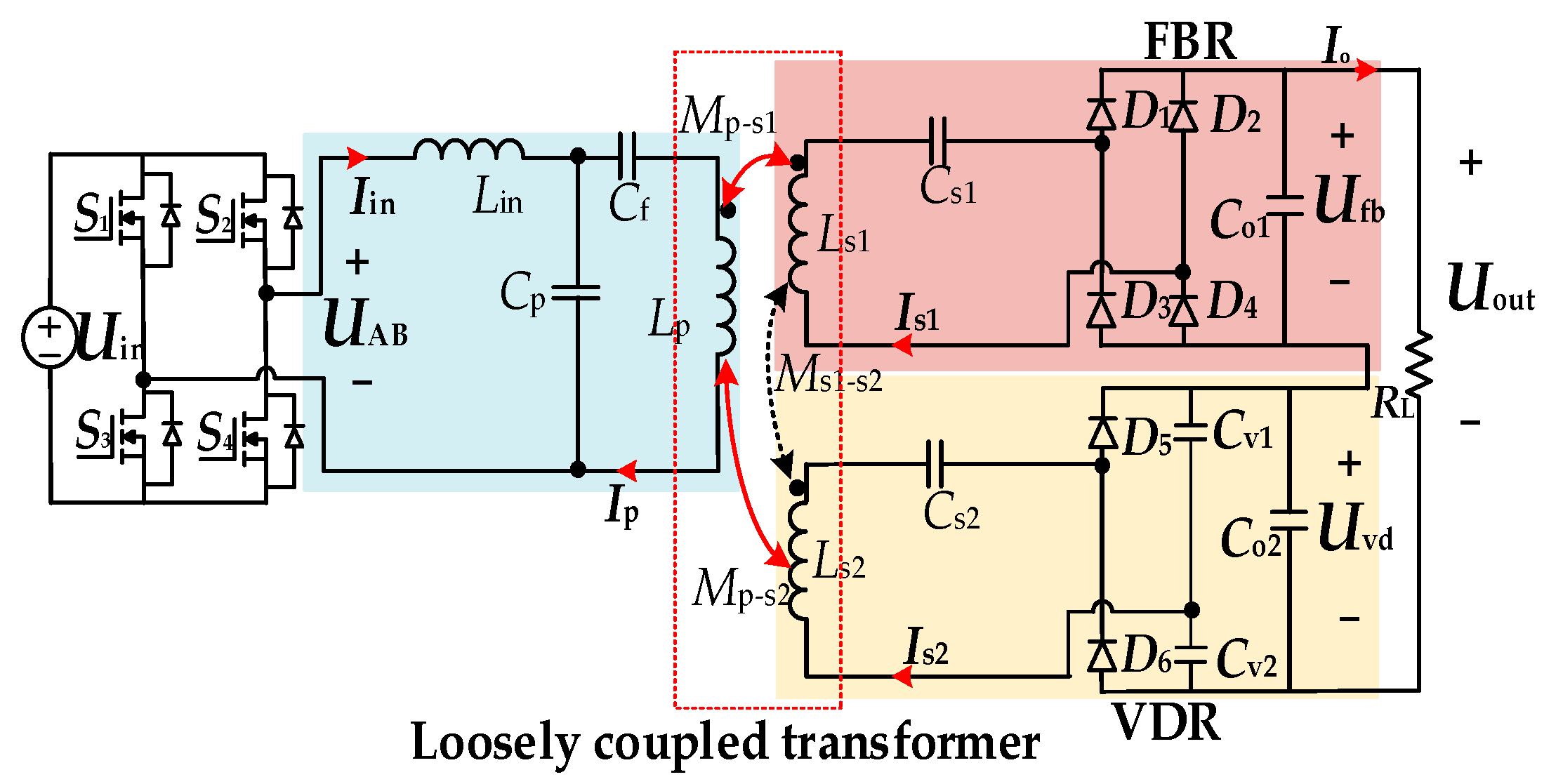
To address power transfer fluctuations caused by receiver misalignment in wireless AGV appliances, this paper proposes a dual-receiver LCC-S compensated IPT system, as shown in Figure 2. The system is powered by a DC voltage Uin, which is converted into high-frequency AC by a full-bridge inverter composed of switches (S1−S4). The LCC compensation network, consisting of an inductor Lin, compensation capacitors Cp and Cf, forms a resonant circuit. The transmitter coil Lp establishes mutual inductances Mp-s1 and Mp-s2 with Ls1 and Ls2, respectively, and Ms-s2 represents the coupling between Ls1 and Ls2. The two receiver coils are connected to different rectifier topologies at the receiver side, forming two power reception paths.
As shown in Figure 2, the red-highlighted path 1 (Ls1) is connected to a compensation capacitor Cs1 and an FBR composed of four diodes (D1D4). This path handles the main power transfer, providing a higher current with improved load regulation and reduced voltage ripples, ensuring efficient energy transmission. The yellow-highlighted path 2: Ls2 is connected to a compensation capacitor Cs2 and a VDR consisting of two diodes (D5, D6) and two capacitors (Cv1, Cv2). This path uses the charge–discharge behavior of capacitors to maintain high output voltage even under weak coupling and low induced voltage conditions through voltage doubling effect, thereby reducing the need for high-turn coils.
The proposed dual-path system enables dual-path power transfer. Under the system is misalignment, the VDR path compensates for the reduced induced voltage in the FBR path, thereby suppressing output voltage fluctuation and enhancing system robustness and efficiency. The performance and advantages of the VDR path will be detailed in this Section 2.2.

2.2. System Analysis

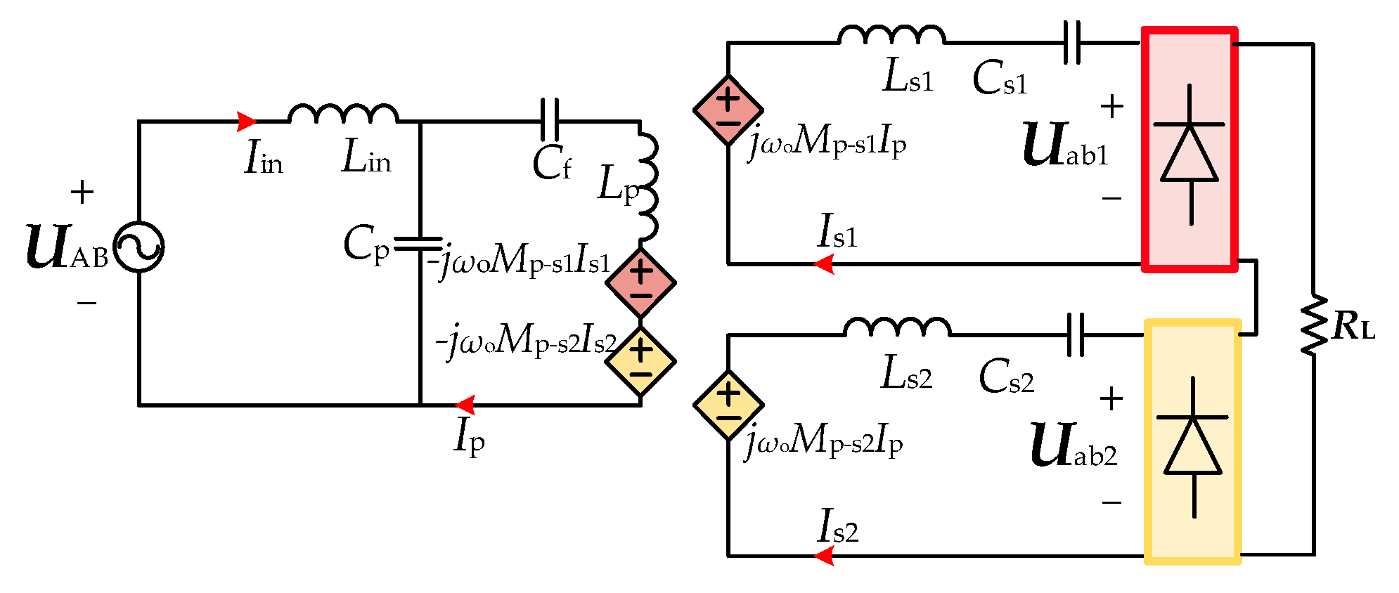
To further analyze the power transfer characteristics, the equivalent circuit model of the proposed dual-receiver IPT system is illustrated in Figure 3. Based on the resonant condition, the AC input voltage UAB on the transmitter side is given by:
U AB   = 2 2 U in π .
ω o = 2 π f o = 1 L in C p = C p + C f L p C p C f = 1 L s 1 C s 1 = 1 L s 2 C s 2 .
According to Kirchhoff’s law, the voltage and current relationships of the proposed IPT system are derived as follows:
U AB = ( j ω o L in + 1 j ω o C p ) I in - 1 j ω o C p I f 0 = ( j ω o L p + 1 j ω o C p + 1 j ω o C f ) I p - j ω o M p s 1 I s 1 - j ω o M p s 2 I s 2 - 1 j ω o C p I in U ab 1 = j ω o M p s 1 I p - ( j ω o L s 1 + 1 j ω o C s 1 ) I s 1 U ab 2 = j ω o M p s 2 I p - ( j ω o L s 2 + 1 j ω o C s 2 ) I s 2 .
From (3), the transmitter side current Ip can be obtained as:
I p = j ω o C p U AB .
The induced voltages Uab1 and Uab2 in receiver coils Ls1 and Ls2 defined as:
U ab 1   = j ω o M p s 1 I p = j ω o ( k p s 1 L p L s 1 ) I p U ab 2   = j ω o M p s 2 I p = j ω o ( k p s 2 L p L s 2 ) I p .
Then, the DC output voltage Uout expressed as:
U out = U fb + U vd = 2 2 π U ab 1 + 2 × 2 2 π U ab 2 = 2 2 π j ω o M p s 1 I p + 2 j ω o M p 2 I p
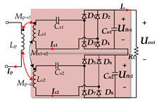
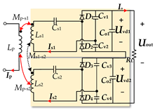
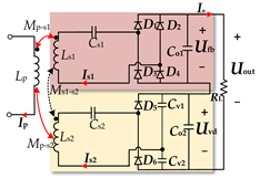
Based on the output voltage expression in (6), three dual-receiver rectification topologies—FBR + FBR, FBR + VDR, and VDR + VDR—are compared under same input and output voltage condition.
Table 1 summarizes the key performance differences in terms of output characteristics, output voltage stability, and magnetic coupling requirements. In the FBR + FBR topology, the output voltage is proportional to the sum of the mutual inductances between the transmitter and each receiver coil. To deliver the rated power, this configuration requires a higher total mutual inductance and increased coil turns, which leads to larger coil volume and higher copper losses. Although this structure exhibits strong voltage regulation and low sensitivity to coupling variation, the bulky magnetic coupler poses challenges for integration in compact systems. In the VDR + VDR configuration, VDR are applied to both receiver paths, effectively doubling the contribution of mutual inductance to the output voltage. This enables the system to operate under weaker coupling conditions with reduced coil size. However, the output voltage becomes highly sensitive to misalignment, and even slight positional deviations can result in significant voltage drops. Moreover, the simultaneous operation of dual voltage-doubler circuits introduces large current ripple and high-frequency harmonics, potentially degrading EMC and overall system stability.
In contrast, the proposed FBR + VDR topology achieves a balanced trade-off between output voltage stability, magnetic coupling design, and spatial adaptability. A FBR is adopted in the main power path to ensure steady output under the alignment. When the main coupling weakens due to lateral displacement, the auxiliary receiver path 2 with VDR helps stabilize the output by picking up additional magnetic flux, thereby improving misalignment tolerance and system robustness. Owing to its low mutual inductance and reduced coil turns, it enhances output voltage without increasing the structure size, helping to reduce magnetic coupling volume and copper loss.
To further quantify the output stability under misalignment conditions, the output voltage fluctuation rate (ΔUout) is introduced and calculated as follows:
Δ U out = U out max - U out min U out max + U out min × 100 % .
The system output power Pout can be represented as follows:
P out   = U out 2 R L = 8 [ ω o 2 ( M p s 1 + 2 M p s 2 ) C p U AB ] 2 P 2 R L .
At the resonant frequency (fo), the compensation topology should satisfy the resonance conditions and can be expressed as follows:
C p = 1 ω 2 L in , C s = 1 ω 2 L s , C f = 1 ω 2 ( L p - L in ) .
The rectifier input voltage can be simplified to the following:
U out = M p s L in U in = 2 2 U dc π .
Based on (6), the Pout of the proposed dual-receiver IPT system is calculated, as shown in (8). It is evident that the Pout strongly depends on the mutual inductances Mp−s1, Mp−-s2. Therefore, optimizing Mp−s1 and Mp−-s2 enhances the capability of the system, thereby improving overall transmitter efficiency. However, Ms1−s2 disrupts the resonant compensation network, causing detuning and reducing system efficiency. Therefore, in magnetic coupling design, Mp−-s1 and Mp−-s2 should be optimized to enhance power transfer capability, while Ms1−s2 should be minimized to reduce resonance detuning, ensuring high-efficiency and stable operation in various conditions.

3. Design and Analysis of the Coupler for the Proposed Compensation Dual-Receiver IPT System

To implement the proposed dual-receiver topology with enhanced misalignment tolerance, this paper introduces a FUSS magnetic coupling structure, comprising two FUS coils serving as the transmitter and first receiver. An auxiliary SS structure coil is integrated on the receiver side to form a dual-receiver IPT system, as shown in Figure 4 and Figure 5. The gray arrows indicate the winding directions of the coils. FEM tools are employed to optimize the magnetic structure and key design parameters, aiming to achieve high efficiency and stable performance.

3.1. Analyze the FUS Magnetic Coupling Structure

In the IPT system, the DDR [13] is defined as the ratio of the transmission distance to the equivalent diameter of the magnetic coupling structure. It is a key parameter influencing system design and can be mathematically expressed as follows:
D D R   = D air   gap D diameter
Here, the Dair gap represents the air gap between the transmitter and receiver coils, while the Ddiameter denotes the equivalent diameter of the magnetic coupling structure. The air gap is set to 185 mm to emulate the typical coil separation distance found in elevated-chassis AGVs, which includes ground clearance, coil housing, and mechanical tolerances.
This setting reflects realistic installation conditions and ensures that the system design is well aligned with practical deployment scenarios. Based on the 185 mm air gap and coil design parameters shown in Figure 4, the DDR value can be calculated using (9), confirming that the proposed system operates under medium DDR conditions with 1 < DDR ≤ 2. This paper focuses on the performance analysis of a medium DDR system.
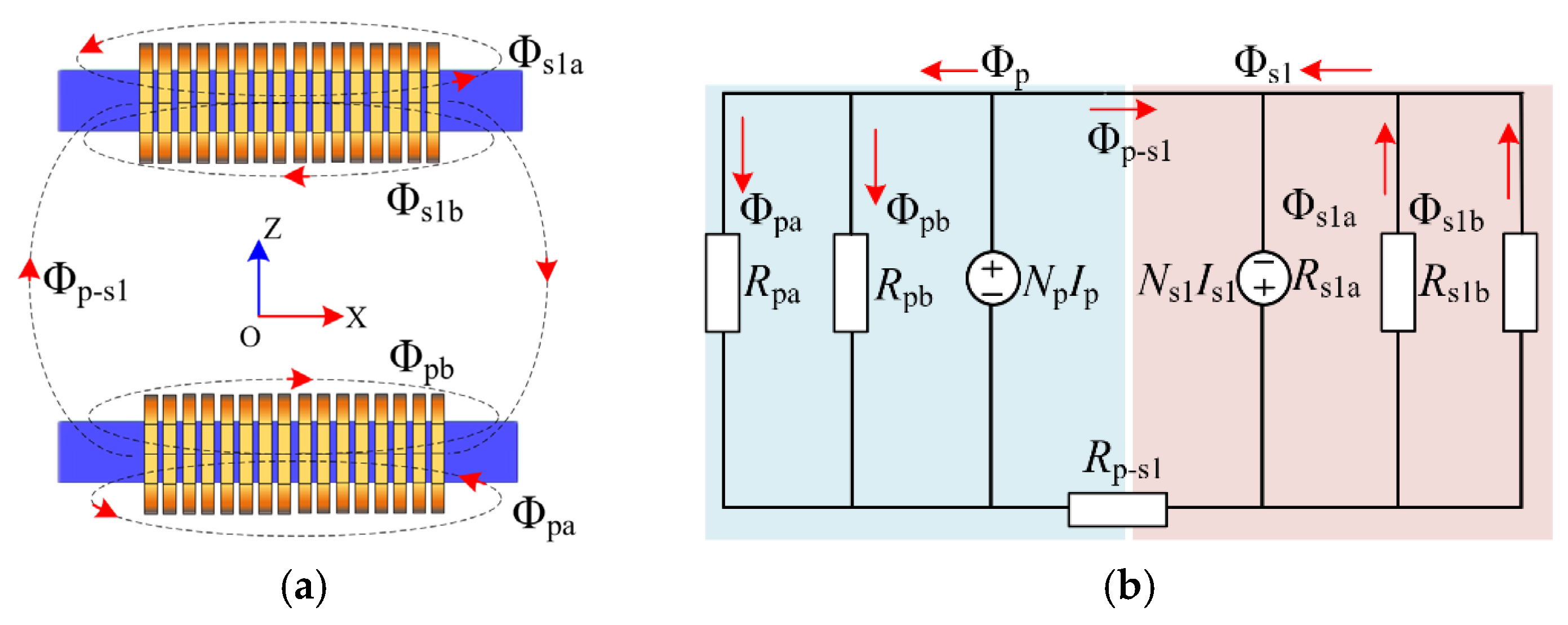
A Flat solenoid (FS) structure coil exhibits strong magnetic field penetration, making it suitable for IPT systems with large transmission distance [12]. However, the FS structure coil magnetic flux tends to spread into the surrounding air, leading to increased leakage flux, reduced power transfer efficiency, and potential electromagnetic interference. To enhance the magnetic coupling performance of the FS coil, Figure 5a illustrates the spatial distribution of magnetic flux, where the dashed lines indicate the primary flux paths. The corresponding equivalent magnetic circuit model is presented in Figure 5b, which provides a theoretical foundation for subsequent magnetic modeling and performance analysis.
Consequently, the magnetic flux expressions for the transmitter and receiver sides are derived based on Hopkinson’s Law:
Φ p   = N p I p R p   Φ s 1   = N s 1 I s R s 1
where Φp and Φs1 are the self-coupled fluxes in the transmitter and receiver coil, Np and Ns1 represent the number of turns in the Lp and Ls1, respectively. Specifically, Rp and Rs1 are the equivalent reluctances for the transmitter and receiver return paths, which can be derived using parallel reluctance combinations, as follows:
R p   = R pa R pb R pa + R pb   R s 1   = R s 1 a R s 1 b R s 1 a + R s 1 b
Here, Rpa and Rpb represent the self-coupling reluctances on the transmitter side, Rs1a and Rs1b denote those on the receiver side. The magnetic reluctance of each path is calculated as:
R p   = R s 1 = l 1 + l 2 + l 3 μ o A
A is the effective cross-sectional area of the magnetic coupling structure, while l1 and l2 denote the magnetic path lengths of the ferrite, and l3 represents the magnetic path length between the transmitter and receiver sides, as shown in Figure 4. μ0 is the permeability of free space. With the above geometric parameters, the mutual inductance can also be expressed as:
M p - s 1 = μ o N p N s 1 A l 1 + l 2 + l 3
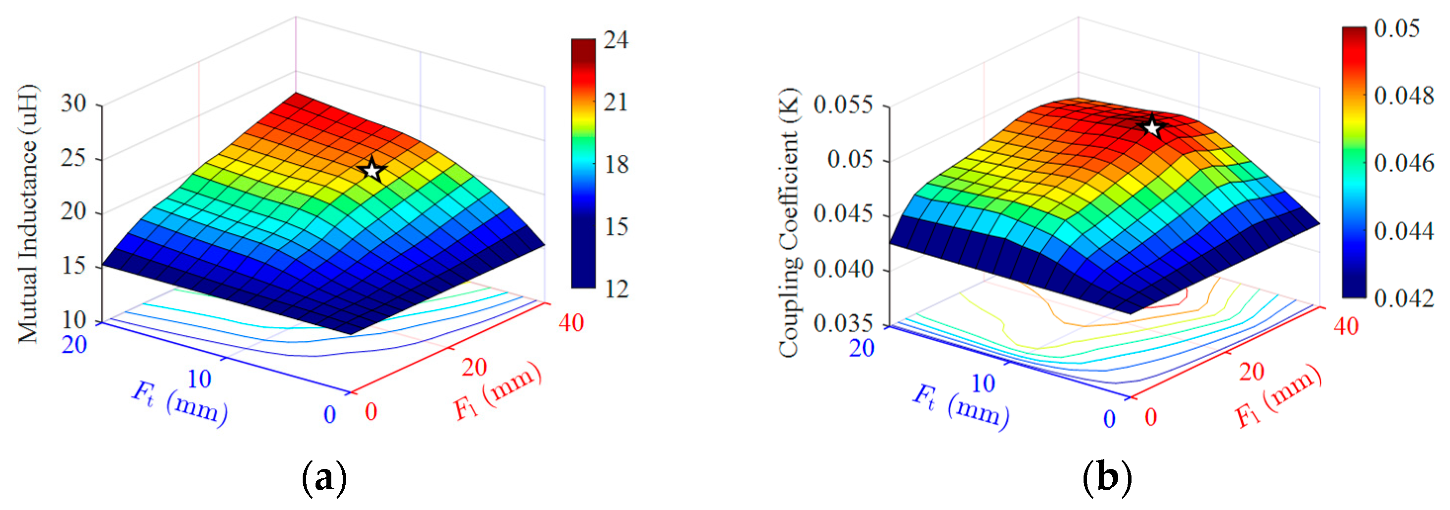
As shown in (12) and (13), the Rp, Rs1 and Mp−s1 are mainly affected by the cross-sectional area of the ferrite core, the number of coil turns, and the length of the magnetic flux path. While increasing the number of turns can help improve mutual inductance, these methods often increase cost and design complexity, making them less suitable for compact IPT systems with limited space. To address this issue, the ferrite structure of the FS coil is optimized in this paper by increasing the cross-sectional area A of the core within the available space the guiding the magnetic flux more effectively, enhances the Mp-s and reduces flux leakage. Following this approach, using FEM to optimize the added ferrite width Fl and thickness Ft while refining the core shape under spatial constraint. To maintain the original coupling structure length, only the Fl and Ft of the ferrite core are adjusted, avoiding an increase in overall system size. And, excessive ferrite dimensions can significantly increase weight and volume, compromising system compactness. Thus, optimizing the core shape within spatial constraints is essential. Figure 6 and Table 2 illustrate the optimization process and detailed parameters of the magnetic coupling structure.
As shown in Figure 6a, increasing Fl and Ft significantly improves Mp−s1. The optimal performance is observed at Ft = 20 mm and Fl = 40 mm, where the magnetic coupler achieves maximum mutual inductance and effectively reduces leakage flux. Although larger values of Fl and Ft can enhance mutual inductance, they are limited by system size constraints. In particular, when Ft exceeds the coil thickness, maintaining a 185 mm transmission distance requires an increased air gap, which negatively affects the coupling.
As depicted in Figure 6b the coupling coefficient kp−s1 slightly decreases. Considering both magnetic performance and system compactness, Ft = 10 mm and Fl = 30 mm are selected as the final design, the selected size is indicated by star markers in Figure 6. Furthermore, the IPT system power transfer efficiency is strongly dependent on the mutual inductance Mp−s1. When the self-inductance of the Lp and Ls1 are closely matched, optimal impedance matching is achieved, minimizing power loss and energy reflection. To ensure efficient power transfer, Ls1 is designed with the same number of turns and a nearly equal self-inductance as Lp, forming the basis for further optimization.
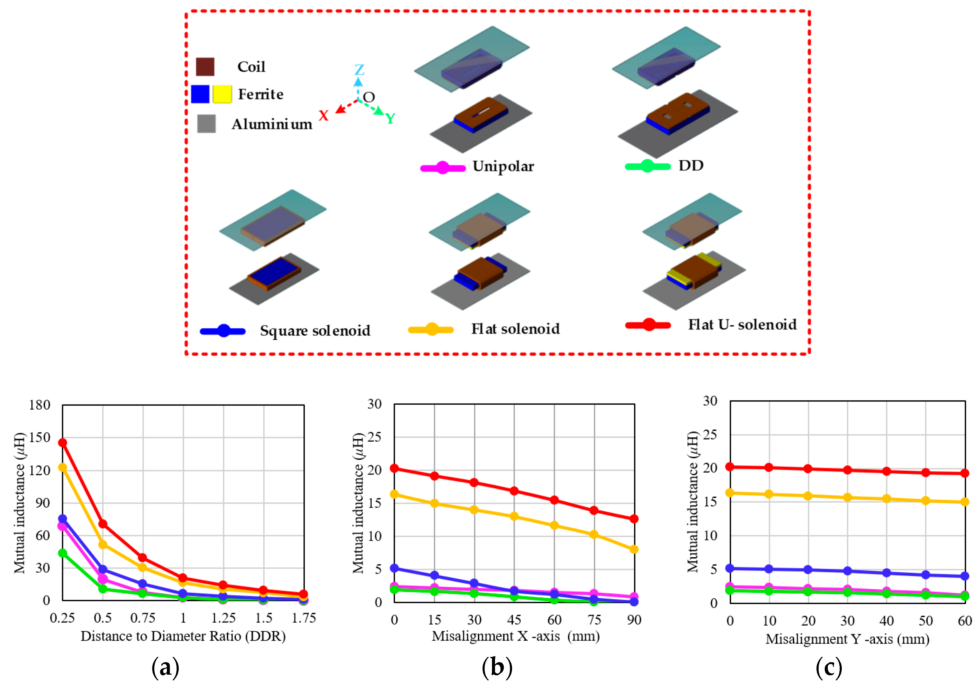
To evaluate the magnetic coupling performance of the proposed FUS coil structure, a comparative simulation study was conducted using the FEM tool among five magnetic coupling configurations under identical conditions of working area, air gap, and copper usage, as illustrated in Figure 7. The evaluated configurations include the unipolar coil, DD coil, SS coil, FS coil, and the proposed FUS coil. In all cases, the transmitter and receiver adopt identical coil structures for modeling. The magnetic coupling performance of each configuration was analyzed under aligned conditions with varying DDR values. Furthermore, the variation in M under X- and Y-axis misalignments was investigated in a medium-DDR system with an air gap of 185 mm analyzed under different DDR in the aligned.
Figure 7a shows the variation in M under different DDR conditions. For all structure coils, M decreases as DDR increases. However, non-planar coils (SS coil, FS coil, and FUS coil), especially the proposed FUS coil, demonstrate superior coupling characteristics due to its optimized geometric design, effectively capturing magnetic flux. Figure 7b illustrates the variation in M for various coil structures under the X-axis misaligned state from 0 to 90 mm. The results indicate that the planar coils (unipolar coil and DD coil) exhibit lower M values in the aligned state, and their M values decrease significantly with misalignment increases. In contrast, the non-planar coils maintain better magnetic coupling characteristics. The FUS coil consistently achieves the highest M value across the X-axis misalignment. Moreover, during energy transfer at long distance, the FUS coil magnetic field expands over a wider spatial range, resulting in a more uniform magnetic flux distribution along the Z-axis. In Figure 7c shows the system is Y-axis misalignment, the wider flux distribution mitigates the reduction in M. The FUS coil exhibits reduced edge flux leakage and a more symmetrical magnetic field distribution, which enhances energy capture efficiency.

3.2. Analysis of the FUSS Magnetic Coupling Structure

As analyzed in the previous section, the M of the FUS coil decreases significantly under X-axis misalignment. To address this issue, a dual-receiver FUSS magnetic coupling structure is proposed. The Lp and Ls1 use two FUS coils, while Ls2 adopts an SS coil. The Ls2 is an auxiliary receiver coil due to its larger cross-sectional area, which enhances magnetic flux capture. Additionally, Ls2 is an orthogonal winding wound around Ls1, forming a compact geometric layout that minimizes system size.
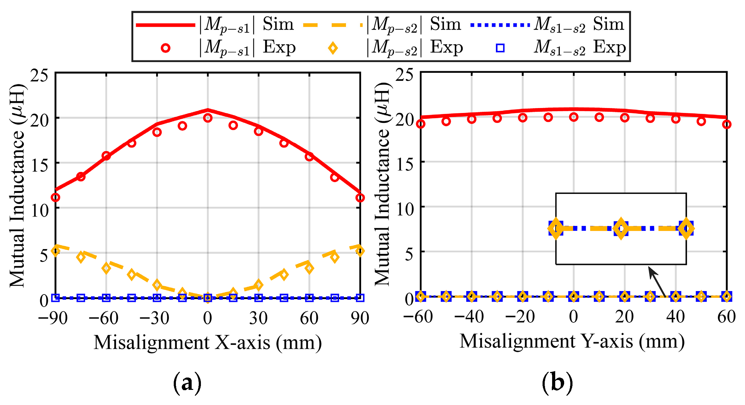
Figure 8 presents the simulation (Sim) and experimental (Exp) mutual inductance variations in the magnetic coupler. When the system is well-aligned, energy transfer primarily occurs between Lp and Ls1, while the auxiliary receiver coil Ls2 remains decoupled with Lp due to coil characteristics, resulting in Mp–s2 being nearly zero. Ls1 and Ls2 are orthogonal arrangements in space, with Ls1 primarily capturing magnetic flux distributed along the Z-axis, while Ls2 captures magnetic flux along the Y-axis. Due to their specificity in magnetic flux capture direction, cross-coupling Ms–s2 is effectively minimized, making it negligible.
As X-axis misalignment increases, Mp-s1 decreases due to the magnetic flux captured by Ls1 decreasing. A portion of the lost flux is captured by Ls2, leading to an increase in Mp-s2 with the misalignment distance, as shown in Figure 8a. However, to reduce the number of turns in the auxiliary coil Ls2 and minimize the system size, the limited turns in Ls2 result in insufficient Mp–s2 to fully compensate for the reduction in Mp–s1, leading to a decrease in equivalent mutual inductance and total Uout. Thus, the voltage doubling effect of the VDR in the auxiliary receiver path is required to further boost the Uout and maintain it within a stable range. In other words, under ±X-axis misalignment, the reduction in Uab1 is caused by the decrease in Mp–s1 is compensated by the increase in Mp–s2, combined with the voltage doubling effect of the VDR, effectively suppressing ΔUout and enhancing the misalignment tolerance of the system, and this design reduces the need for high turn coils and reduces thermal stress and EMI performance.
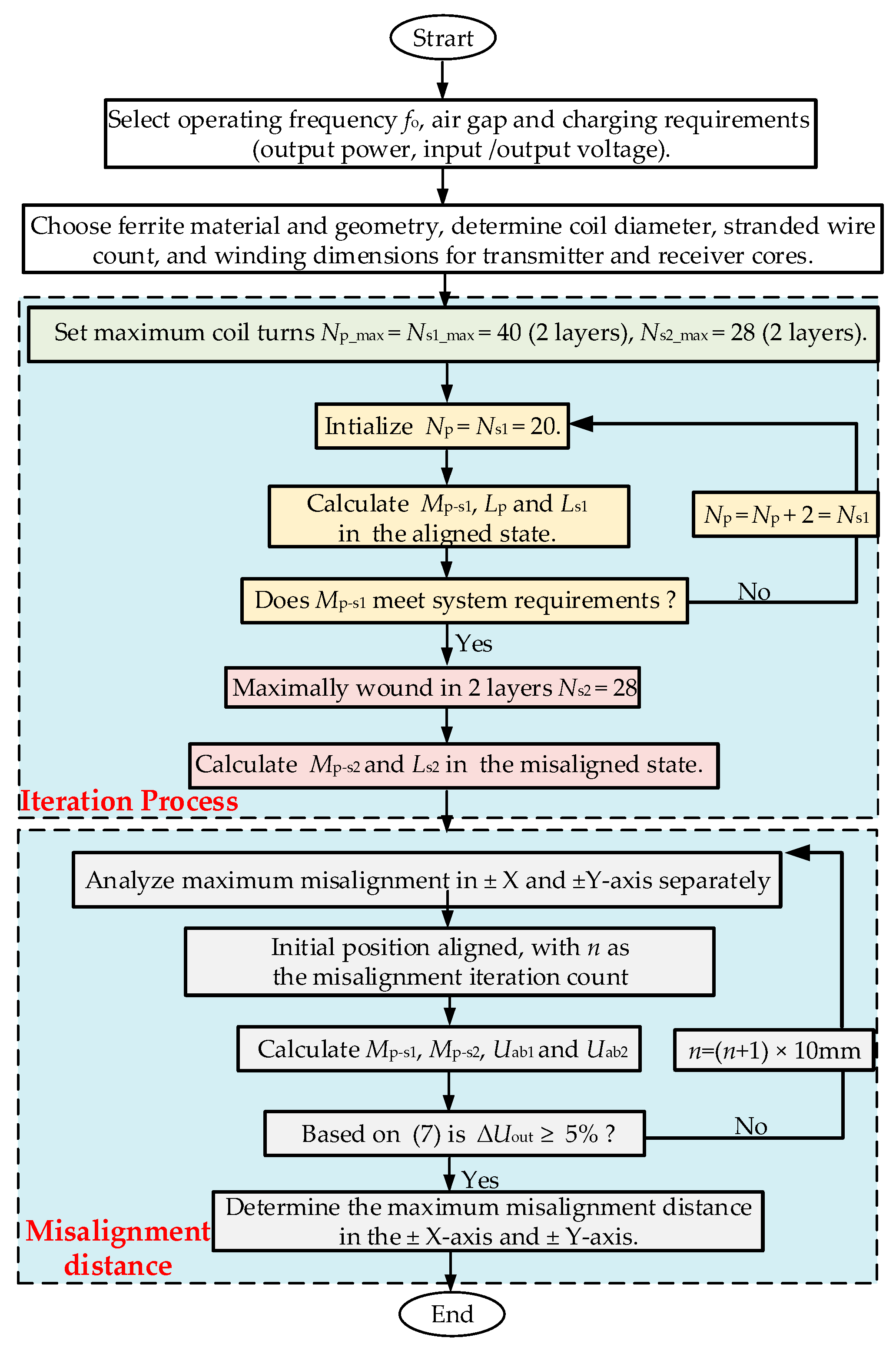
In addition, as shown in Figure 8b, under ±Y-axis misalignment, Mp–s1 decreases with increased misalignment, but the decline is slight. This indicates that the proposed structure exhibits good misalignment tolerance in the ±Y-axis direction, slowing down the rate of decrease in transmission performance. To optimize the dual-receiver IPT system, FEM simulation was used to design the coil turns in the magnetic coupling structure in Figure 9. The power and voltage requirements were first determined, followed by selecting ferrite material and defining coil dimensions. The initial number of turns for Lp and Ls1 was set to 20, mainly considering the limited winding space, the need for moderate self-inductance, and the simplicity of single-layer winding. This setting ensures reasonable initial coupling performance and serves as a practical basis for subsequent FEM-based optimization. The number of turns was then gradually increased to 40 using a two-layer winding structure to improve mutual and self-inductance while keeping copper loss low. The Ls2 was designed with a maximum turn count of 28, optimized to keep ΔUout below 5% under the misaligned state. By gradually adjusting the misalignment distance, the maximum tolerable misalignment was determined as 51.4% (±90 mm) along the X-axis and 51.7% (±60 mm) along the Y-axis, ensuring that ΔUout remained within 5%.
Figure 10 compares the magnetic flux density distribution under the same system parameters for cases of the FUS structure coil and with the FUSS structure coil at 90 mm X-axis misalignment. Z-axis cross-sectional analysis shows that the FUSS structure coil significantly enhances the magnetic field on the receiver side, improving flux capture capability. Additionally, the designed aluminum shielding plate effectively suppresses vertical magnetic leakage, creating a low-field region around the magnetic coupler, indicated in purple in Figure 10. At 190 mm from the coupling center, the flux density remains safe, with the blue region showing only 11 µT, well below international electromagnetic exposure limits. This ensures compliance with electromagnetic safety standards and makes the system suitable for wireless AGV applications.
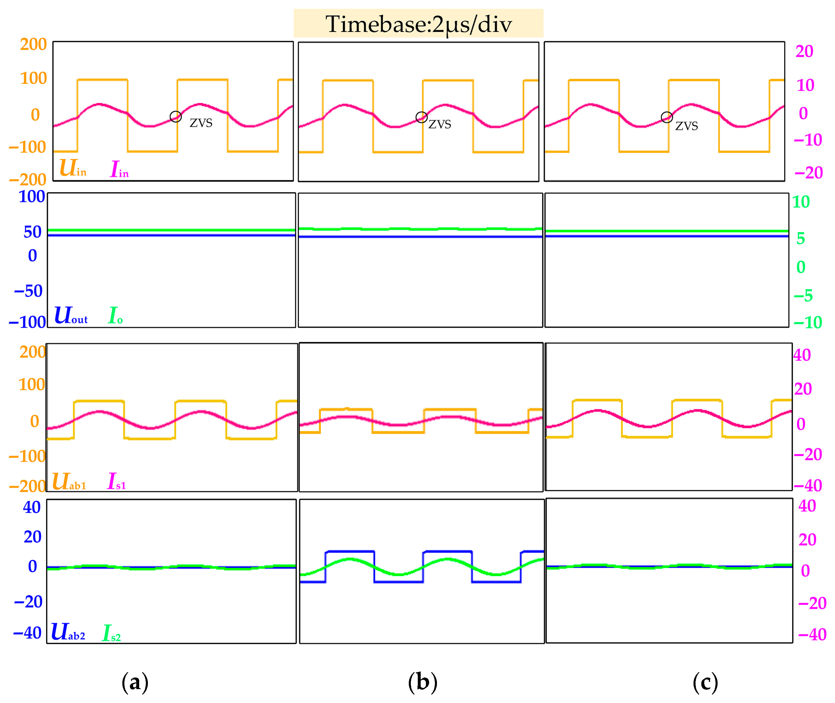
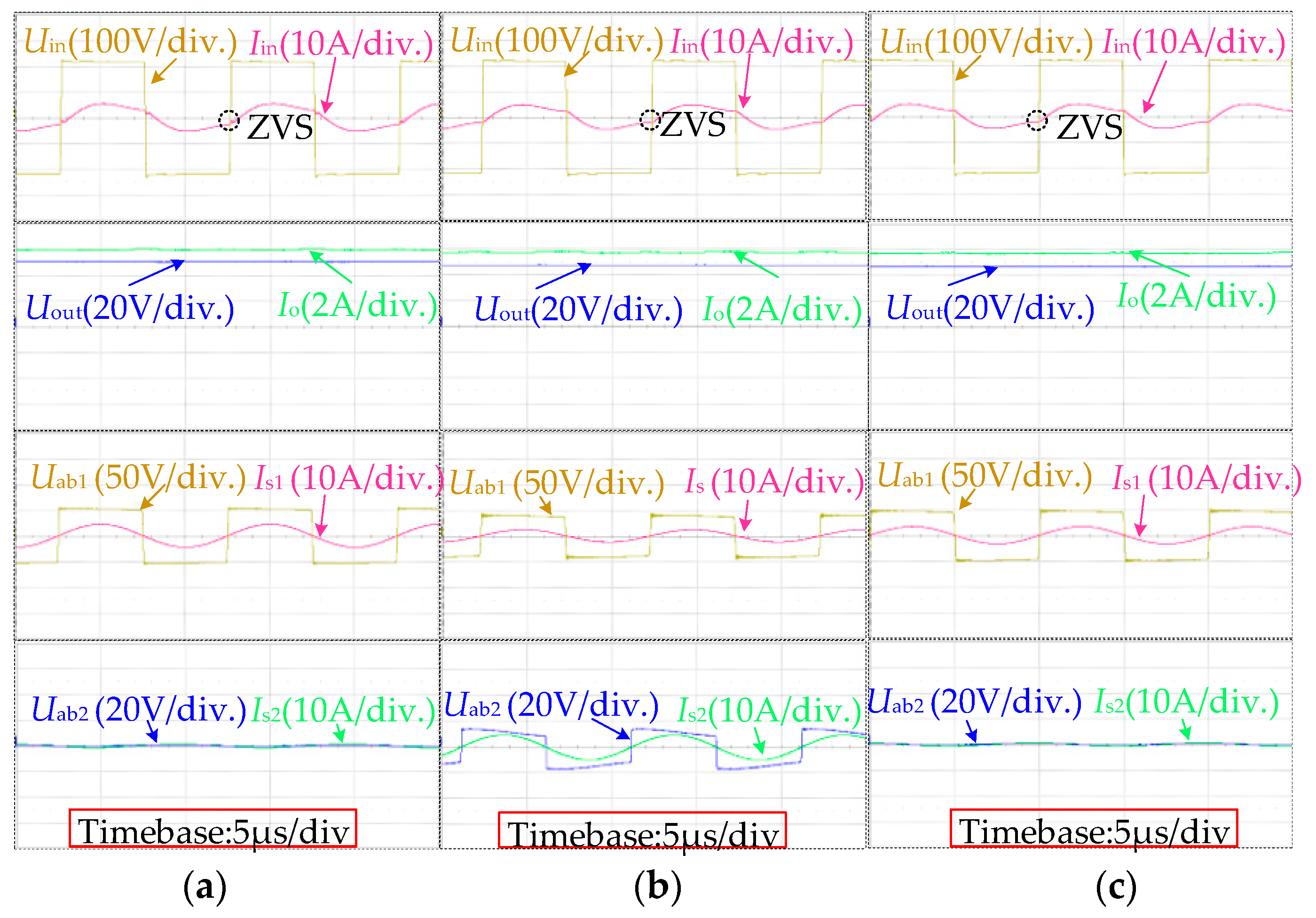
To further confirm the operating mechanism, simulations were carried out at 100 kHz with Uin = 110 V, DDR = 1.03, and a constant load. The results show in Figure 11 that the inverter keeps ZVS in both aligned and misaligned cases, while Uout only drops slightly with misalignment. This comes from the complementary behavior of the two paths: as X-axis misaligned increases, the coupling to the FUS coil decreases and Uab1 falls, but the SS coil intercepts more magnetic flux so Mp–s2 increases and Uab2 rises. Along the Y-axis misalignment, the SS coil stays almost decoupled, so Uab2 is nearly constant and Uab1 decreases smoothly. These simulations confirm that the proposed FUSS coupler with the hybrid FBR + VDR can keep ΔUout small under misalignment.

4. Experimental Verification

To evaluate the performance and misalignment tolerance of the proposed FUSS structure coil in a medium DDR IPT system, an experimental prototype was developed with dimensions the same as the simulation model, as shown in Figure 11.
Considering that AC resistance in the magnetic coupling structure is a major part of system loss, litz wires with 1700 strands of 0.12 mm diameter are adopted for the transmitter and first receiver coils in the FUS and FS structures, while litz wire. with 500 strands of 0.1 mm diameter is utilized for the SS auxiliary receiver coil, to reduce skin and proximity effects. To minimize core loss, PM12 ferrite material from TODA ISU was selected due to its low magnetic loss at high frequencies. The detailed experimental design parameters are summarized in Table 3.
First, to verify the performance of the FUS structure coil, a comparative test was conducted between magnetic coupling structures where the transmitter and receiver coils were FUS and FS structure coils under 300 W and 50 V system conditions. As shown in Figure 11, under the same coil length and air gap, the IPT system with the FUS structure coil achieved a maximum efficiency of 83.5%, significantly higher than the 79.54% efficiency of the FS structure coil. This indicates that the FUS structure coil effectively enhances system performance by reducing leakage flux and improving magnetic coupling.
To evaluate the proposed FUSS structure misalignment tolerance, further misalignment tests were conducted on the dual-receiver FUSS structure IPT system with a 185 mm air gap. As shown in Figure 12, the experimental waveforms and the Uout variations in both transmission paths include an aligned and X/Y-axis misaligned state in Figure 13.
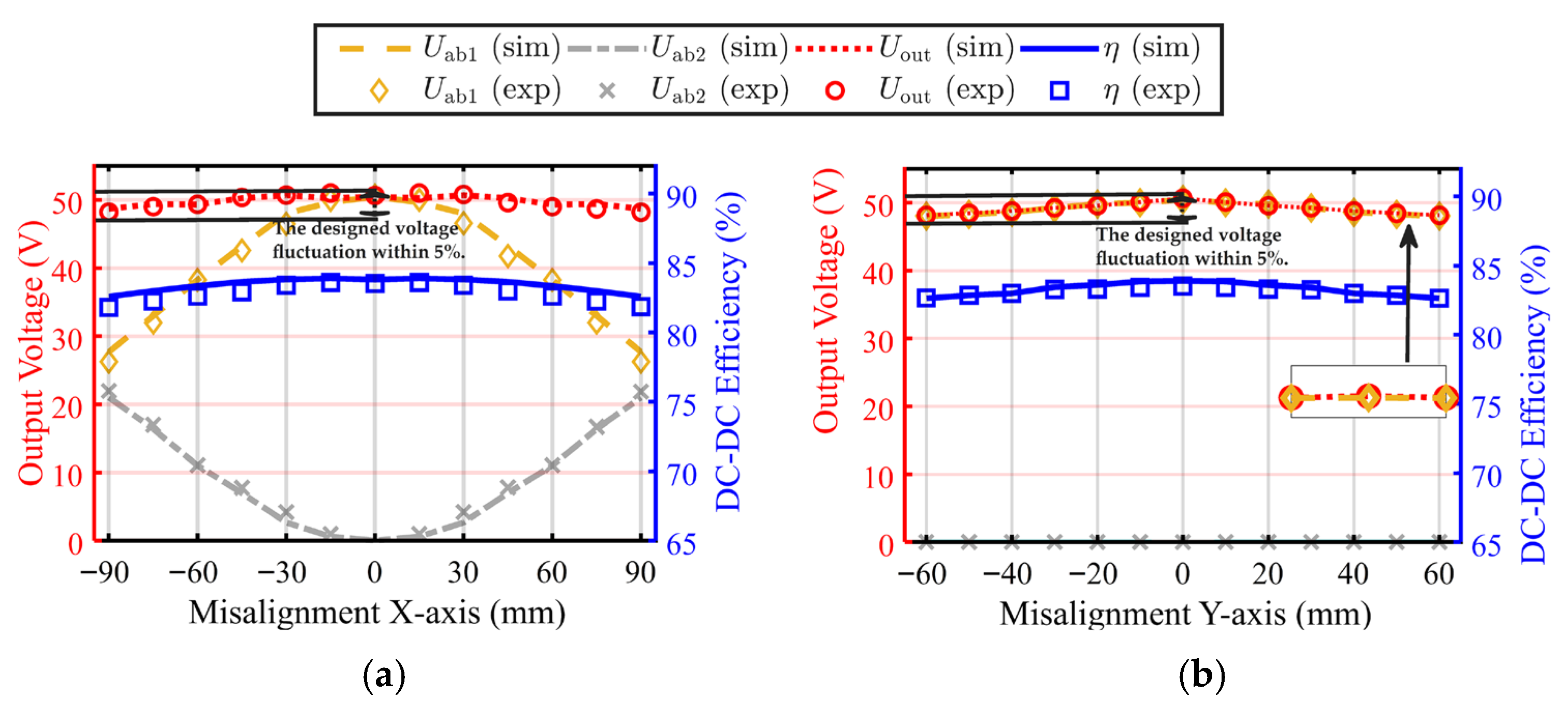
Figure 13a shows the system in the aligned state, Lp and Ls2 remain decoupling, and energy transfer occurs mainly through Ls1, where Uab2 and Is2 exhibit a linear relationship. To further clarify the output stability under misalignment case, experimental results are presented in Figure 13b and Figure 14a. As the X-axis misalignment increases, the mutual inductance Mp–s1 between the transmitter and the first receiver coil decreases, which reduces Uab1. At the same time, the SS coil intercepts more magnetic flux, leading to an increase in the VDR branch voltage Uab2. With the voltage-doubling effect of the VDR, the reduction in Uab1 is effectively compensated, and the ΔUout is suppressed within 4.92%, with Uout decreasing from 50.64 V to 48.15 V at 90 mm misalignment. In contrast, under Y-axis misalignment, the SS coil does decouple with the transmitter coil, so the VDR branch voltage remains nearly unchanged. Only the FUS coil contributes, and Uab2 gradually decreases with misalignment case. Due to the solenoid coil geometry, the Y-axis misalignment coupling weakens more gradually than the X-axis, leading to a slower decline. As shown in Figure 14a, at 60 mm Y-axis misalignment, Uout decreases from 50.64 V to 48.20 V, corresponding to ΔUout = 4.82%. The DC-DC efficiency η decreases only slightly, from 83.51% at the aligned state to 81.86% at 90 mm X-axis misalignment and 82.05% at 60 mm Y-axis misalignment, remaining above 80% across the tested range. The complementary effect ensures that the proposed FUSS structure maintains less than 5% ΔUout and efficiency above 80% under more than 51% misalignment, demonstrating robustness in medium DDR systems.
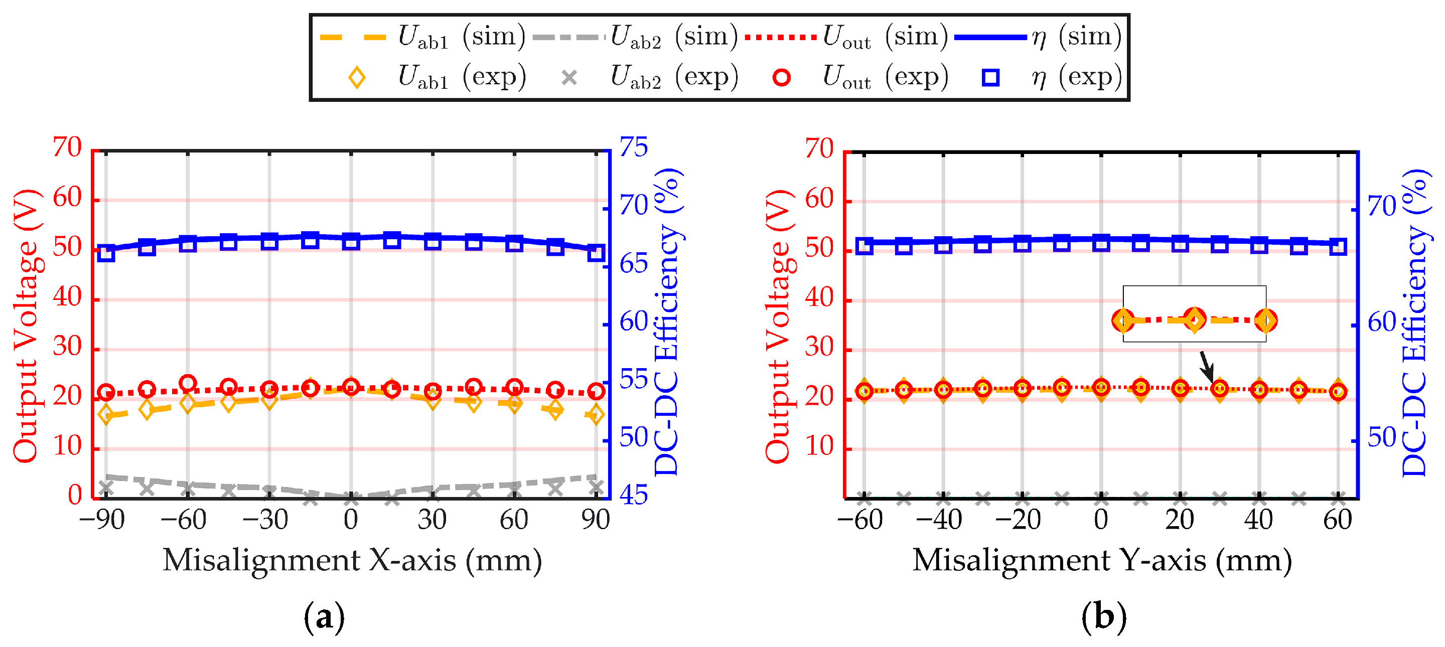
The simulation and experimental results when the system is misaligned along the Z-axis to an air gap of 270 mm, corresponding to DDR = 1.5, as illustrated in Figure 15. The results indicate that as the transmission distance increases, Mp−s1 slightly decreases, leading to a minor reduction in Uout. However, at DDR = 1.5, the system maintains a relatively stable Uout and ƞ under ±X-axis and ±Y-axis misalignment, confirming that the proposed dual-receiver coil structure effectively suppresses the ΔUout, ensures stable output voltage, and enhances power transfer efficiency, thereby demonstrating its robustness and superior performance in medium DDR IPT systems.
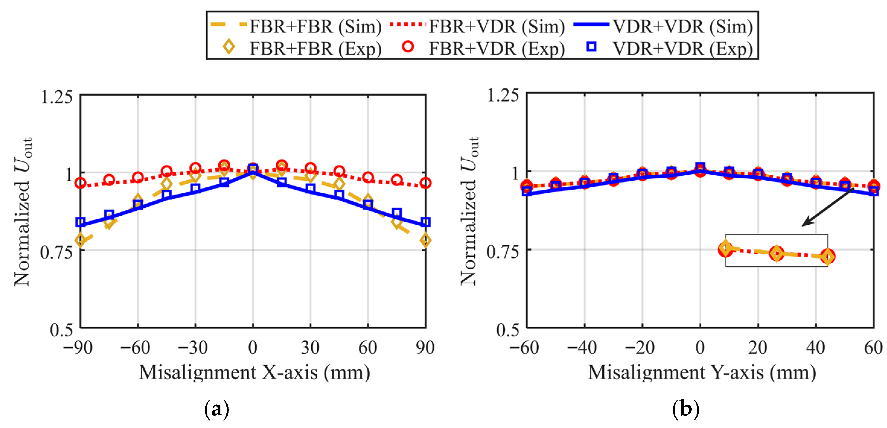
Figure 16 shows the normalized Uout under X-axis and Y-axis misalignment for the dual-receiver IPT system using three different rectifier topologies: FBR + FBR, FBR + VDR, and VDR + VDR. All systems use the same input voltage and magnetic coupling structure, so the voltage stability under misalignment reflects the sensitivity of each topology to changes in magnetic coupling. Under X-axis misalignment, both FBR + FBR and VDR + VDR show Uout as misalignment increases with minimal fluctuation. In contrast, FBR + VDR keeps the voltage more stable with the smallest variation, showing better misalignment tolerance. For Y-axis misalignment, FBR + FBR and FBR + VDR show similar and stable voltage trends. This is because the auxiliary coil Ls2 cannot capture magnetic flux from the Ls2 when misaligned in Y-axis, so most power is transferred through the two FUS coils only. As a result, the benefit of the auxiliary coil is limited. In this case, VDR + VDR exhibits a slight decrease in Uout, meaning it is more sensitive to changes in coupling. Overall, the FBR + VDR system performs best in X- and Y-axis, with more stable output voltage and stronger tolerance to misalignment.
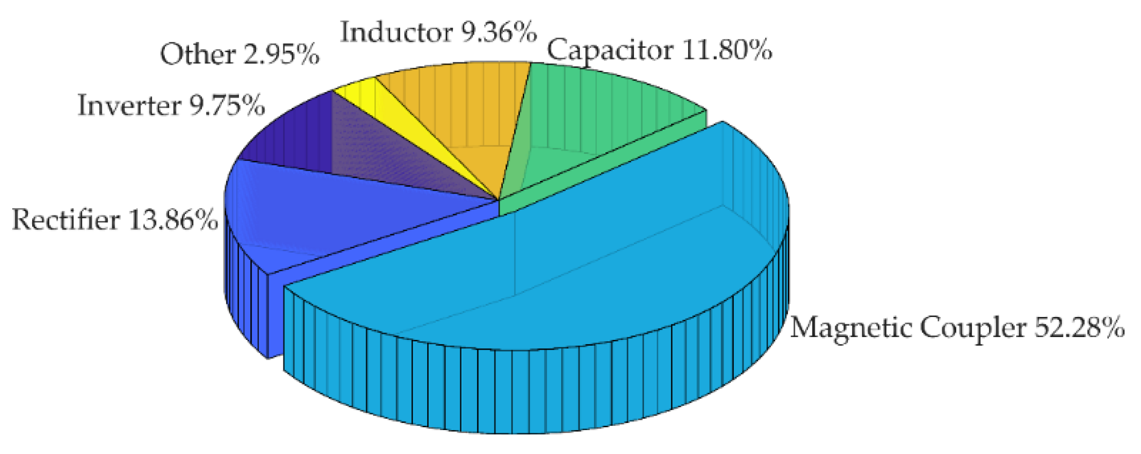
The loss distribution of the proposed IPT system at 300 W, as shown in Figure 17. The total loss is 59.3 W. System losses were measured with a power analyzer, and each component’s share was estimated from measured RMS quantities and datasheet/ESR parameters. The magnetic coupler is the dominant contributor. These results highlight that the magnetic structure plays the most critical role in determining system efficiency, and further improvements should therefore focus on optimizing the coupler design.
To comprehensively evaluate the proposed FUSS coupling structure in medium DDR system, Table 4 provides a detailed comparison with representative designs reported in the literature. In terms of spatial compactness and transmission distance, the FUSS structure achieves a DDR of 1.03 while maintaining a compact magnetic pad size of 183 × 125 mm. This performance significantly exceeds that of existing designs with DDR values below 0.5, particularly those in [26], which adopt large 400 × 400 mm coil structures but yield only 0.2 and 0.37 DDR. In the misalignment tolerance, the FUSS system demonstrates highly balanced performance with 51.4% and 51.7% tolerance along the X- and Y-axis, respectively. This contrasts with systems like [21], where although a high tolerance of 172% is achieved along the X-axis, it comes at the cost of increased magnetic volume and higher circuit complexity, hindering system integration. From the perspective of circuit design, the FUSS system employs a hybrid FBR + VDR rectification topology, requiring only six diodes for stable operation. Compared to [20,21], and [26] that require 8 diodes, this topology reduces circuit complexity. Additionally, the output voltage fluctuation of the proposed system remains within 5% under misalignment conditions, ensuring robust voltage regulation and favorable EMC. By optimizing the ferrite geometry and spatial layout, the proposed FUSS coil structure significantly reduces the magnetic core volume and copper utilization. This enables higher integration density and improved manufacturability, especially when compared to the large-area, high-turn coil assemblies employed in conventional long-distance IPT systems. In summary, the FUSS structure achieves a favorable balance among key performance metrics, including voltage stability, magnetic design, misalignment robustness, and compactness. These advantages make it a promising solution for IPT in medium DDR applications, particularly in AGV systems where spatial constraints and misalignment are critical.
Despite the good performance of the proposed FUSS system, some limits and challenges should be noted. When scaling the system above 1 kW, RMS current and AC copper loss increases, and the stress on power devices becomes higher. To keep high efficiency, thicker litz wire, and maybe synchronous rectification are needed. The magnetic core also must be checked again for saturation and coil heating, and the LCC-S compensation may need returning to keep ZVS. At higher operating frequency, the coil can be smaller, and coupling may improve but switching loss and EMI/EMC problems become more serious, so extra filtering and shielding are required. Furthermore, vertical and angular misalignment sensitivity has not been fully characterized and requires further study. These factors outline the practical challenges for scaling the proposed FUSS system to higher power and higher frequency ranges. In addition, the prototype was only tested in a stationary case. For dynamic IPT when AGVs are moving, the coupling changes quickly, which can cause voltage fluctuation. This may need segmented primaries, adaptive frequency or phase control, and alignment detection to ensure a stable output. These points show the main engineering limits when moving to higher power, higher frequency, and dynamic charging, and they will guide our future research.

5. Conclusions

This paper proposes a dual-receiver magnetic coupling structure based on FUS and SS coils, which demonstrates superior magnetic coupling efficiency under medium DDR conditions, significantly improving power transfer performance. The dual-receiver structure coil operates synergistically to improve misalignment tolerance. Additionally, the system employs an FBR + VDR hybrid rectifier topology, which not only reduces the number of coil turns and minimizes system volume but also effectively suppresses output voltage fluctuations under misalignment conditions, thereby improving the robustness and reliability of the system. Experimental results show that under DDR = 1.03, the system achieves a power transfer efficiency of 83.51%. When subjected to ±51.4% X-axis and ±51.7% Y-axis misalignment, the output voltage fluctuation remains within 5%, fully validating the good misalignment tolerance and stable power delivery capability of the system. Beyond the AGV application, the same medium DDR, high misalignment tolerance is applicable to UAV, autonomous mobile and service robots, and industrial vehicles and AS/RS shuttles. These platforms share constraints of medium DDR, compact couplers, and pronounced misalignment tolerance. Future research will further optimize magnetic coupling characteristics and explore adaptive control strategies to enhance system performance under dynamic operating conditions.

Author Contributions

Conceptualization, J.X., G.L. and D.-H.K.; Data curation, J.X. and Z.Y.; Formal analysis, J.X. and Z.Y.; Funding acquisition, D.-H.K.; Investigation, G.L. and D.-H.K.; Project administration, S.J. and D.-H.K.; Writing—original draft, J.X.; Writing—review and editing, D.-H.K. All authors have read and agreed to the published version of the manuscript.

Funding

This work was supported by the Technology Innovation Program (20026706, Development of 200 kW high-efficiency booster converter manufacturing technology for hydrogen fuel cell electric vehicle/UAM) funded by the Ministry of Trade, Industry & Energy (MOTIE, Korea).

Data Availability Statement

The original contributions presented in this study are included in the article. Further inquiries can be directed to the corresponding author.

Conflicts of Interest

The authors declare no conflict of interest.

References

  1. Zeng, Y.; Clerckx, B.; Zhang, R. Communications and signals design for wireless power transmission. IEEE Trans. Commun. 2017, 65, 2264–2290. [Google Scholar] [CrossRef]
  2. Zhang, Z.; Pang, H.; Georgiadis, A.; Cecati, C. Wireless power transfer—An overview. IEEE Trans. Ind. Electron. 2019, 66, 1044–1058. [Google Scholar] [CrossRef]
  3. Li, L.; Xu, Y.; Zhang, Z.; Yin, J.; Chen, W.; Han, Z. A prediction-based charging policy and interference mitigation approach in the wireless powered Internet of Things. IEEE J. Sel. Areas Commun. 2019, 37, 439–451. [Google Scholar] [CrossRef]
  4. Yu, X.; Feng, J.; Zhu, L.; Li, Q. Design and optimization of a planar omnidirectional wireless power transfer system for consumer electronics. IEEE Open J. Power Electron. 2024, 5, 311–322. [Google Scholar] [CrossRef]
  5. Hoang, H.; Lee, S.; Kim, Y.; Choi, Y.; Bien, F. An adaptive technique to improve wireless power transfer for consumer electronics. IEEE Trans. Consum. Electron. 2012, 58, 327–332. [Google Scholar] [CrossRef]
  6. Xia, C.; Liu, L.; Liu, Y.; Ma, Z. IPT system for tail-free household appliances in the smart home system. IET Power Electron. 2019, 12, 1002–1010. [Google Scholar] [CrossRef]
  7. Budhia, M.; Boys, J.T.; Covic, G.A.; Huang, C.-Y. Development of a single-sided flux magnetic coupler for electric vehicle IPT charging systems. IEEE Trans. Ind. Electron. 2013, 60, 318–328. [Google Scholar] [CrossRef]
  8. Zaheer, A.; Hao, H.; Covic, G.A.; Kacprzak, D. Investigation of multiple decoupled coil primary pad topologies in lumped IPT systems for interoperable electric vehicle charging. IEEE Trans. Power Electron. 2015, 30, 1937–1955. [Google Scholar] [CrossRef]
  9. Lu, F.; Zhang, Y.; Zhang, H.; Zhu, C.; Diao, L.; Gong, M.; Zhang, W.; Mi, C.C. A low-voltage and high-current inductive power transfer system with low harmonics for automatic guided vehicles. IEEE Trans. Veh. Technol. 2019, 68, 3351–3360. [Google Scholar] [CrossRef]
  10. Qu, Y.; Zhang, B.; Gu, W.; Shu, X. Wireless power transfer system with high-order compensation network based on parity-time-symmetric principle and relay coil. IEEE Trans. Power Electron. 2023, 38, 1314–1323. [Google Scholar] [CrossRef]
  11. Liu, X.; Jin, D.; Ji, H.; Liu, L.; Xia, C. Research on mutual inductance identification and efficiency optimization of the three-coil wireless power transfer systems with switchable relay coil. IEEE Trans. Power Electron. 2024, 39, 6492–6503. [Google Scholar] [CrossRef]
  12. Choi, B.G.; Kim, J.H.; Lee, E.S.; Kim, H.R.; Rim, C.T. Optimal dipole-coil ampere-turns design for maximum power efficiency of IPT. IEEE Trans. Power Electron. 2020, 35, 7317–7327. [Google Scholar] [CrossRef]
  13. Wang, Y.; Gu, P.; Yao, Y.; Xu, D. Analysis and design of cubic magnetic coupler for high distance-to-diameter ratio IPT systems. IEEE Trans. Ind. Electron. 2022, 69, 409–419. [Google Scholar] [CrossRef]
  14. Fu, C.; Wang, D.; Zhao, Q. A compact and coupling-smooth magnetic coupler design for AGV wireless charging application. IEEE Access 2023, 11, 11288–11297. [Google Scholar] [CrossRef]
  15. Ramezani, A.; Narimani, M. A new wireless EV charging system with integrated DC–DC magnetic element. IEEE Trans. Transp. Electrif. 2019, 5, 1112–1123. [Google Scholar] [CrossRef]
  16. Darvish, P.; Cao, H.; Uddin, M.F.; Wang, H.; Zhao, Y. A generic coupled and/or decoupled integrated inductors optimization for WPT applications. IEEE Trans. Power Electron. 2025, 40, 15976–16003. [Google Scholar] [CrossRef]
  17. Lin, H.; Cai, C.; Wu, S.; Jiao, Y.; Chai, W.; Yu, J. Compact and misalignment tolerance IPT system based on sine-cosine coupling superposition for autonomous underwater vehicle applications. IEEE Trans. Transp. Electrif. 2025, 11, 6940–6951. [Google Scholar] [CrossRef]
  18. Mai, J.; Wang, Y.; Yao, Y.; Sun, M.; Xu, D. High-misalignment-tolerant IPT systems with solenoid and double D pads. IEEE Trans. Ind. Electron. 2022, 69, 3527–3535. [Google Scholar] [CrossRef]
  19. Zhang, C.; Lu, W.; Zhao, J.; Wu, X.; Chen, H.; Xu, D. A novel asymmetric magnetic coupler applied to multiple-receiver wireless charging system for automated guided vehicles. IEEE Trans. Power Electron. 2023, 38, 14761–14775. [Google Scholar] [CrossRef]
  20. Mai, R.; Luo, Y.; Yang, B.; Song, Y.; Liu, S.; He, Z. Decoupling circuit for automated guided vehicles IPT charging systems with dual receivers. IEEE Trans. Power Electron. 2020, 35, 6652–6657. [Google Scholar] [CrossRef]
  21. Li, G.; Zhang, H.; Chen, Y.; Xie, J.; Jo, C.-H.; Zhu, C.; Cui, S.; Kim, D.-H. An integrated mutually compensatory dual receiver for AGV misalignment-tolerant IPT charging. IEEE Trans. Circuits Syst. II Express Briefs 2024, 72, 313–317. [Google Scholar] [CrossRef]
  22. Li, G.; Zhang, H.; Chen, Y.; Yin, Y.; Liu, A.; Li, Z.; Zhang, M. Design and implementation of a coupled complementary IPT system for extensive misalignment tolerance and CC/CV outputs. IEEE Trans. Transp. Electrif. 2025, 11, 8390–8403. [Google Scholar] [CrossRef]
  23. Shen, Z.; Zhou, H.; Xie, R.; Zhuang, Y.; Mao, X.; Zhang, Y. A strong offset-resistant electric vehicle wireless charging system based on dual decoupled receiving coils. IEEE Trans. Ind. Electron. 2024, 71, 15216–15219. [Google Scholar] [CrossRef]
  24. Imtiaz, T.; Elsanabary, A.; Mubin, M.; Soon, T.K.; Mekhilef, S. Enhancing misalignment tolerance using naturally decoupled identical dual-transmitter–dual-receiver coils for wireless EV charging system. IEEE J. Emerg. Sel. Top. Power Electron. 2024, 12, 5337–5351. [Google Scholar] [CrossRef]
  25. Darvish, P.; Hossain, A.; Mekhilef, S.; Tey, K.S.; Mubin, M.B.; Yin, J.; Akhtar, M.M.; Mustafa, A.; Khalid, H.; Imtiaz, T.; et al. Dual-receiver based naturally decoupled coil structure with improved rotational misalignment tolerance for WPT systems. IEEE Trans. Transp. Electrif. 2024, 10, 5412–5423. [Google Scholar] [CrossRef]
  26. Xu, H.; Huang, Z.; Li, X.L.; Tse, C.K. Misalignment-tolerant IPT coupler with enhanced magnetic flux variation suppression and reduced copper usage. IEEE Trans. Power Electron. 2024, 39, 10506–10517. [Google Scholar] [CrossRef]
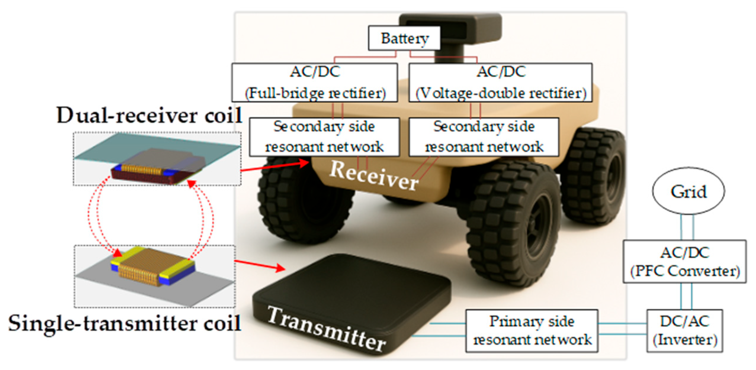
Figure 1. Typical EV stationery IPT system.
Applsci 15 09799 g001
Figure 2. Configuration of the proposed dual-receiver LCC-S IPT system.
Applsci 15 09799 g002
Figure 3. The equivalent circuits of the proposed dual-receiver LCC-S IPT system.
Applsci 15 09799 g003
Figure 4. (a) Proposed magnetic coupling structure, (b) side view and (c) top and bottom view.
Applsci 15 09799 g004
Figure 5. Magnetic characteristics of the FS structure: (a) magnetic flux distribution and (b) equivalent magnetic circuit model.
Applsci 15 09799 g005
Figure 6. FEM simulation results with a 185 mm air gap under aligned case, showing variation in coupling performance after ferrite-shape optimization. Only the Fl and Ft dimensions are varied. (a) change in mutual inductance, (b) change in coupling coefficient.
Applsci 15 09799 g006
Figure 7. Variation in mutual inductance of five same-sized magnetic structures at different positions based on FEM simulations. (a) Under different DDR values, (b) misalignment in the X-axis, and (c) misalignment in the Y-axis.
Applsci 15 09799 g007
Figure 8. Simulated and measured mutual inductance with 185 mm air gap. (a) misalignment in ±X-axis, (b) misalignment in ±Y-axis.
Applsci 15 09799 g008
Figure 9. Design flow of magnetic coupling structure.
Applsci 15 09799 g009
Figure 10. Magnetic field distribution at 100 kHz with a 185 mm air gap and 90 mm X-axis misalignment: (a) FUS coil, (b) FUSS coil.
Applsci 15 09799 g010
Figure 11. Experimental waveforms of the system under different states. (a) aligned, (b) X-axis misalignment of 90 mm. (c) Y-axis misalignment of 60 mm.
Applsci 15 09799 g011
Figure 12. (a) Experimental prototype, (b) power analyzer data in the aligned state of the proposed FUS structure coil and (c) power analyzer data in the aligned state of the FS structure coil.
Applsci 15 09799 g012
Figure 13. Simulated and measured results at DDR = 1.03 with a 185 mm air gap and an input voltage of 110 V: (a) alignment, (b) misalignment along ±X-axis, (c) misalignment along ±Y-axis.
Applsci 15 09799 g013
Figure 14. Simulated and measured results with 185 mm airgap DDR is 1.03. (a) misalignment in the ±X-axis, (b) misalignment in the ±Y-axis.
Applsci 15 09799 g014
Figure 15. Simulated and measured results at 100 kHz with Z-axis misalignment with 270 mm air gap (DDR = 1.5), and an input voltage of 110 V: (a) misalignment along ±X-axis; (b) misalignment along ±Y-axis.
Applsci 15 09799 g015
Figure 16. Comparison of Uout variations in a dual-receiver IPT system utilizing FBR + FBR, VDR + VDR and FBR + VDR rectification structure under a 185 mm air gap, (a) X-axis misalignment and (b) Y-axis misalignment.
Applsci 15 09799 g016
Figure 17. Loss breakdown.
Applsci 15 09799 g017
Table 1. Performance Comparison of different Rectification Topologies in Dual-Receiver IPT Systems.
Rectification Combination TypeFBR + FBRVDR + VDRFBR + VDR
Applsci 15 09799 i001Applsci 15 09799 i002Applsci 15 09799 i003
Output Voltage U out = 2 2 π j ω o I p M p s 1 + M p s 2 U ou t = 2 2 π j ω o I p 2 M p s 1 + 2 M p s 2 U out = 2 2 π j ω o I p M p s 1 + 2 M p s 2
Uout sensitivity to misalignmentLowHighMedium
Relative Ls2 copper usageHighMediumSmall
Table 2. The detailed parameters of the magnetic coupler.
VariableSelected Value
Transmitter coilSize of 110 mm × 116 mm × 38 mm
Transmitter coil turns40 turns
First-receiver coilSize of 110 mm × 116 mm × 38 mm
First-receiver turns40 turns
Second-receiver coilSize of 183 mm × 125 mm × 30 mm
Second-receiver turns28 turns
Air gap185 mm
Ferrite platePM12 (TODA ISU)
Table 3. Essential parameters of the proposed system.
VariableSelected ValueVariableSelected Value
Uin110 VLp417.82 μH
Uout50 VLs1415.23 μH
Pout300 WLs2207.66 μH
fo100 kHZLin39.55μH
k0.047Cp64.07 nF
Mp–s119.85 μHCf6.70 nF
Mp–s20.08 μHCs16.10 nF
Ms1–s20.06 μHCs212.20 nF
Table 4. Comparison with other methods.
Proposed inRef. [18]Ref. [20]Ref. [21]Ref. [26]This Paper
Coil structureSDDPCoaxial dual receiverIMCDRRSPFUSS
Maximum pad size (mm)250 × 200100 × 100220 × 180300 × 300183 × 125
Air gap (mm)50504560185
DDR0.220.50.280.21.03
Misalignment X-axis44%N/D172%50%51.4%
Misalignment Y-axis67%N/DN/DN/D51.7%
Number of Diodes48886
Output fluctuation<6%N/D<5.82%<10.8%<5%
Maximum power0.3 kW0.3 kW0.54 kW1 kW0.3 kW
Magnetic coupler volume (mm3)☆☆☆☆☆☆☆☆
N/D: Not defined or not reported in corresponding reference. ☆: Small magnetic coupler volume. ☆☆: Relatively larger magnetic coupler volume.
Disclaimer/Publisher’s Note: The statements, opinions and data contained in all publications are solely those of the individual author(s) and contributor(s) and not of MDPI and/or the editor(s). MDPI and/or the editor(s) disclaim responsibility for any injury to people or property resulting from any ideas, methods, instructions or products referred to in the content.