Article

Hydraulic Fracturing Pressure-Relief Technology for Controlling the Surrounding Rock in Deep Dynamic Pressure Roadways

by
Jianxi Ren
*,
Kai Su
and
Chengwei Sun
School of Architecture and Civil Engineering, Xi’an University of Science and Technology, Xi’an 710054, China
*
Author to whom correspondence should be addressed.
Appl. Sci. 2025, 15(17), 9779; https://doi.org/10.3390/app15179779 (registering DOI)
Submission received: 29 July 2025 / Revised: 28 August 2025 / Accepted: 2 September 2025 / Published: 5 September 2025

Abstract

In the context where the surrounding rock of deep coal mine roadways is in a complex mechanical environment of “three highs and one disturbance”, mining disturbances are prone to cause instability and damage to the roadways, and the severe deformation of the south wing main roadway caused by mining disturbances in the 2404 working face of a certain mine in the Jiaoping Mining Area restricts safe production. In order to reduce the deformation and damage of the south wing main roadway affected by long-term dynamic pressure, this study proposes a determination method of key rock strata for top cutting pressure relief and the pressure-relief method along the stress transmission path of the south wing main roadway. It completes the design and field test of the hydraulic fracturing scheme for the hard roof of the 2404 transportation roadway, and evaluates the pressure-relief effect through means such as pressure curves, mine pressure manifestation laws, and borehole observation. The results show that hydraulic fracturing significantly weakens the strength of the roof rock strata, forms through cracks between the pressure-relief holes, reduces the average working resistance of the support by 18% after fracturing, and reduces the average pressure step distance of the roof by 34%. During the mining process, the stress variation range of the coal pillar is small, and there is no obvious deformation or damage to the surrounding rock and support structure of the south wing main roadway. It effectively cuts off the stress transmission path of the hard roof and controls the deformation of the roadway, providing technical support for the control of surrounding rock in deep dynamic pressure roadways.

1. Introduction

1.1. Research Background and Significance

Deeply buried dynamic pressure roadways are highly susceptible to large deformations in the surrounding rock under the influence of high ground stress and dynamic pressure disturbances caused by adjacent coal mining operations. In severe cases, this can lead to the failure of support structures and even trigger rock bursts, posing a serious threat to the safe production of coal mines [1,2,3,4,5,6]. Conventional support measures do not fundamentally address the impact of strong roof pressure when dealing with deformation in tunnels subjected to strong dynamic pressure. They often fail to effectively control deformation and failure of the surrounding rock in the tunnel. It is necessary to address the stresses in the surrounding rock environment by using hydraulic fracturing technology to weaken the integrity of the overlying rock layers above the tunnel support coal pillars and create a weakened zone. This reduces the peak residual stress while transferring it deeper into the surrounding rock, thereby achieving pressure relief and tunnel support [7,8,9,10,11,12,13,14,15,16,17]. Therefore, there is an urgent need to conduct research on the hydraulic fracturing pressure-relief mechanism of deeply buried dynamic pressure tunnels and rock mass deformation control technology.
Hydraulic fracturing technology has been widely used in coal mine roadway roof caving and pressure relief [18,19]. Niu Tonghui [20] analyzed the stress characteristics of hard roof overburden and its impact on mine pressure manifestation, proposing the use of hydraulic fracturing technology to weaken hard roof overburden and revealing its mechanism for reducing mining pressure manifestation. Cheng Lixing et al. [21,22,23,24] used numerical simulation, rock beam mechanics models, and field engineering verification to conclude that hydraulic fracturing mainly achieves pressure relief by weakening the integrity of the roof and implementing stress transfer paths, which can significantly reduce the roof pressure step distance and dynamic load coefficient, effectively addressing dynamic disasters caused by hard roofs. Kang Hongpu et al. [25,26,27,28] proposed a directional hydraulic fracturing roadway pressure-relief technology to address the challenge of high-stress roadway support in deep Wells. They also optimized the fracturing methods and processes by studying the extension patterns of hydraulic fractures under different conditions. Although hydraulic fracturing technology has been applied in dealing with dynamic disasters in coal mines, the significant differences in coal mine strata make it impossible to apply the existing hydraulic fracturing pressure-relief methods [29,30]. On the negative side, hydraulic fracturing can cause the injected fluid to leak into the aquifer. Moreover, in the process of gas and coal co-mining, it is used to ensure the stability of underground degassing boreholes. Its environmental benefits will reduce the amount of methane emitted by coal mines into the atmosphere. Therefore, in the application process, the pressure-relief effect of hydraulic fracturing is difficult to reflect directly and is hard to evaluate effectively.
This paper takes the hydraulic fracturing project of the roof of the transportation tunnel in the 2404 working face of a certain mine in the Jiaoping Mining Area as its research background. It addresses the issue of uncontrollable deformation of the surrounding rock in the south wing main tunnel caused by the disturbance from adjacent working faces during mining operations. Based on on-site sampling of the roof and laboratory mechanical tests, this study proposes a method for determining the key rock layers for roof cutting and pressure relief in deeply buried dynamic pressure tunnels. It elucidates the mechanism of hydraulic fracturing for pressure relief in deeply buried coal mine dynamic pressure tunnels, suggests pressure-relief methods along the stress transmission path of the south wing main tunnel, completes the design of the hydraulic fracturing pressure-relief scheme, and conducts on-site industrial trials. By integrating on-site observations, pressure curves, mine pressure monitoring, and digital drilling, the effectiveness of hydraulic fracturing pressure relief is evaluated. Compared with previous studies, the determination of key layers in this paper is more in line with actual engineering, solving the problem of disconnection between theory and the actual situation on site. Moreover, considering the single pressure-relief effect evaluation and analysis in some literature, the diversified evaluation system in this paper is more complete. The research results can provide technical support for the deformation control of the south wing main roadway of this mine and have reference value for similar mines.

1.2. Regional Overview and Overlying Rock Characteristicss

Located in the Jiaoping Mining District, the 2404 working face within the 4-2 coal seam has an average burial depth of 650 m. South of this face, the south wing main tunnels—comprising the conveyor and track tunnels—parallel the coal seam’s strike direction. A 90-m coal pillar separates the south wing conveyor from the 2404 face, while the conveyor and track tunnel are spaced 50 m apart (spatial relationships shown in Figure 1). At the 2404 working face, the coal seam thickness ranges from 5.0 to 10.0 m (averaging 7.5 m), classifying it as a thick coal seam. Figure 2 presents the borehole columnar section revealing the stratigraphy. The direct roof comprises gray to gray-black medium-fine sandstone averaging 16.3 m in thickness, classified as moderately stable to unstable. Locally, a 1-m-thick carbonaceous mudstone pseudo-roof underlies the direct roof. The main roof consists of light gray medium-coarse sandstone averaging 38.05 m thickness, classified as moderately stable. The roof rock mass predominantly contains medium-fine and medium-coarse sandstone, exhibiting intact rock properties.

1.3. Current Major Issues

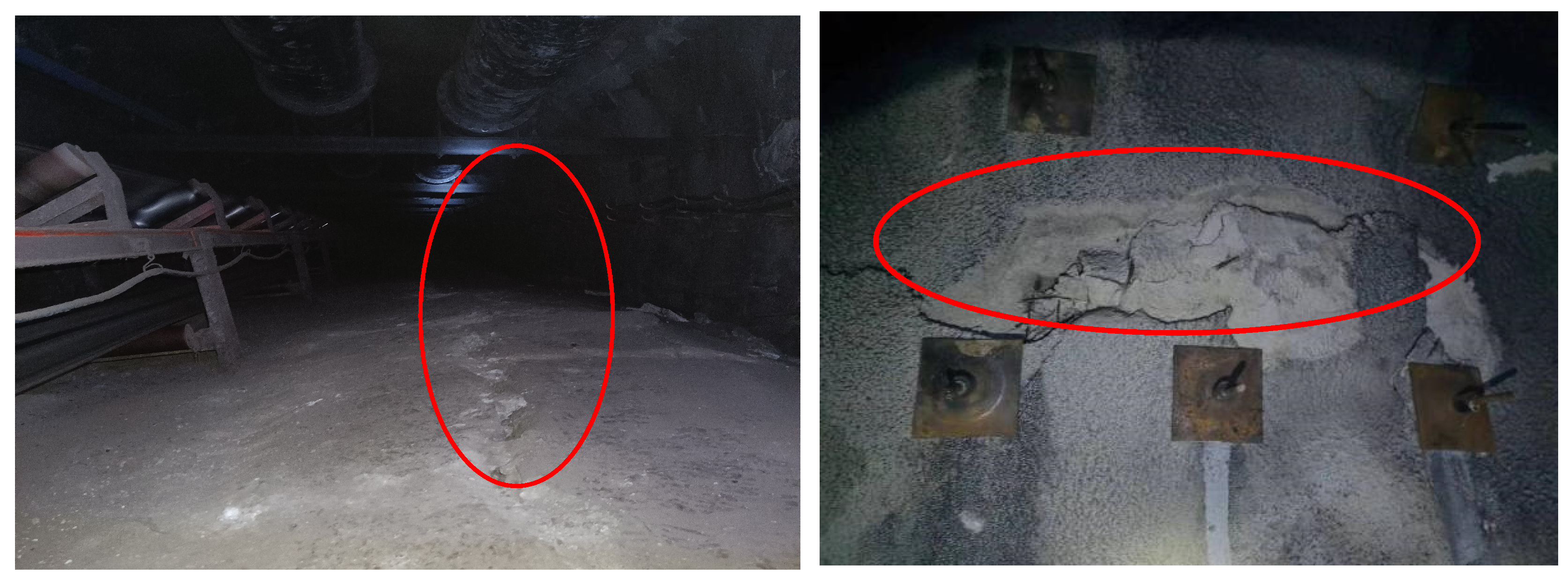
The south wing main tunnel exists within a complex geological environment characterized by high in situ stress, elevated temperatures, significant permeability, and substantial mining-induced disturbance. In sections of the 2404 transportation tunnel lacking fracturing treatment, mine pressure manifestations are particularly pronounced. As evidenced in Figure 3, the south wing main tunnel exhibits severe deformation, including localized anchor cable failure and rupture. Significant convergence deformation is especially evident in the surrounding rock adjacent to the coal pillar. These observations indicate that the tunnel has been substantially impacted by mining activities at the 2404 working face. Deformation and damage in specific tunnel sections result from the combined effects of mining-induced dynamic stresses and static stresses exerted by lateral support structures.
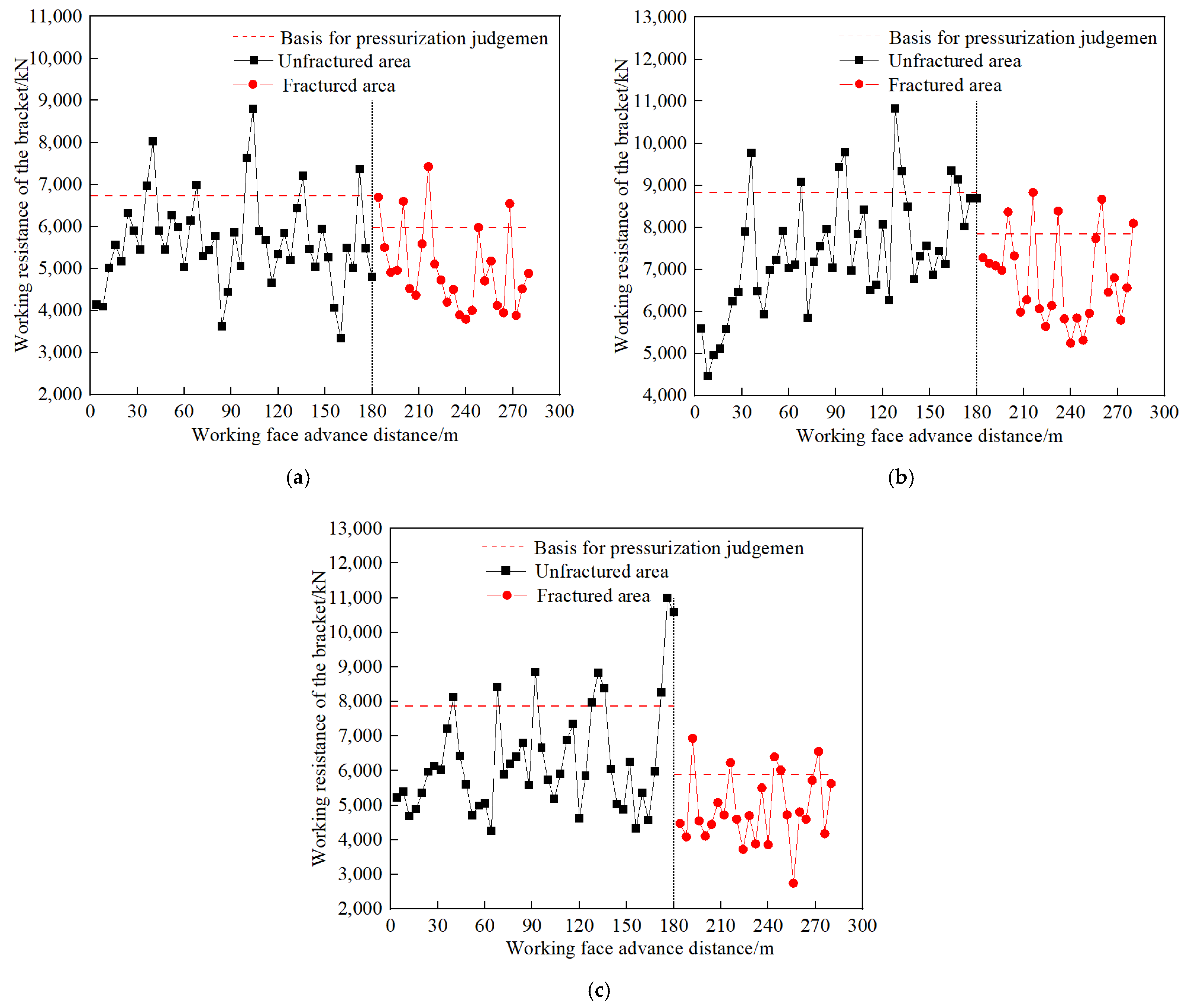
Figure 4 illustrates the hydraulic support pressure variation within the goaf (caved zone) of the 2404 working face. The dashed line represents the threshold for significant mine pressure manifestation. When a support’s working resistance exceeds this threshold, mining-induced pressure becomes apparent in the adjacent tunnel. Table 1 summarizes pressure step statistics during the 2404 face advance. As shown in Figure 4, support working resistance exhibits cyclic fluctuations as mining progresses. At an advance distance of 32–36 m, working resistance in the upper, middle, and lower measurement zones reaches 8000–10,000 kN. Crossing the pressure threshold at ~33.3 m, advance distance indicates initial pressure onset. Subsequent resistance peaks above this threshold represent individual pressure cycles; the distance between consecutive peaks defines the pressure cycle interval.
The initial pressure step distance averages 33.3 m, while the periodic pressure interval averages 27 m. This larger initial step distance indicates severe mine pressure manifestations. The immediate roof strata of the 2404 working face exhibit significant thickness and high integrity, comprising high-strength sandstone (Figure 2). Such thick, competent roofs resist caving after coal extraction, forming extensive suspended spans. This behavior contributes to the observed large initial and periodic pressure step distances.
Furthermore, coal pillars within the south wing main tunnel bear not only the overlying roof load but also additional stress transferred laterally from adjacent suspended roof sections. Consequently, surrounding rock stresses near these pillars are elevated, adversely impacting the stability of both the tunnel perimeter and its support structures.
Therefore, to mitigate the destabilizing coupling of mining-induced cyclic pressures and lateral support stresses during 2404 face advance and to prevent deformation damage in the south wing main tunnel hydraulic fracturing technology must be implemented for roof cutting and pressure relief in the 2404 transportation tunnel. This intervention is essential for ensuring the south wing main tunnel’s long-term stability.

2. Materials and Methods

2.1. Basic Principles of Hydraulic Fracturing Pressure Relief

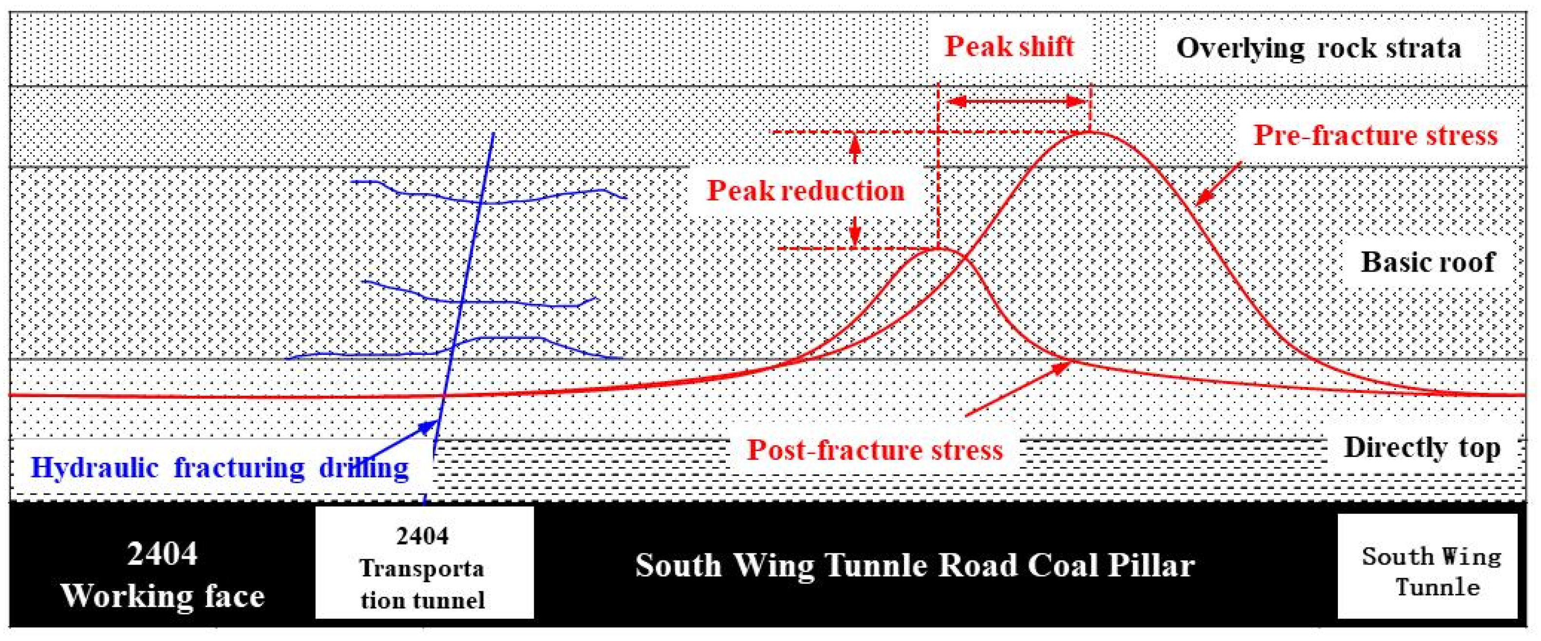
Figure 5 schematically illustrates stress transfer during hydraulic fracturing in the 2404 transportation tunnel roof. This technology injects pressurized fluid into boreholes to initiate and propagate fractures within the target rock layer, deliberately weakening the overlying strata above the support pillar. This creates a fracture-damaged zone which, under mining-induced stresses, experiences fracture reactivation and enhanced fragmentation. Consequently, the rock’s load-bearing capacity is significantly reduced. This process transfers supporting stresses from the coal-rock mass to deeper intact strata while isolating stress transmission pathways, achieving effective destress and control objectives.

2.2. Hydraulic Fracturing Scheme Design

2.2.1. Key Stratum Analysis of Roof Stability

Based on borehole logs and geological data, the 4-2 coal seam within the 2404 working face exhibits lateral continuity with an average thickness of 7.5 m. This thickness parameter is applied to Equation (1) to determine the required fracturing height for targeted hydraulic intervention.
H m = M ( K 1 ) cos α
In the formula, Hm is the height to be processed; M is the coal seam mining thickness, taken as 7.5 m; K is the rock fragmentation coefficient, taken as 1.15 for medium-hard rock; α is the coal seam dip angle, taken as 4°.
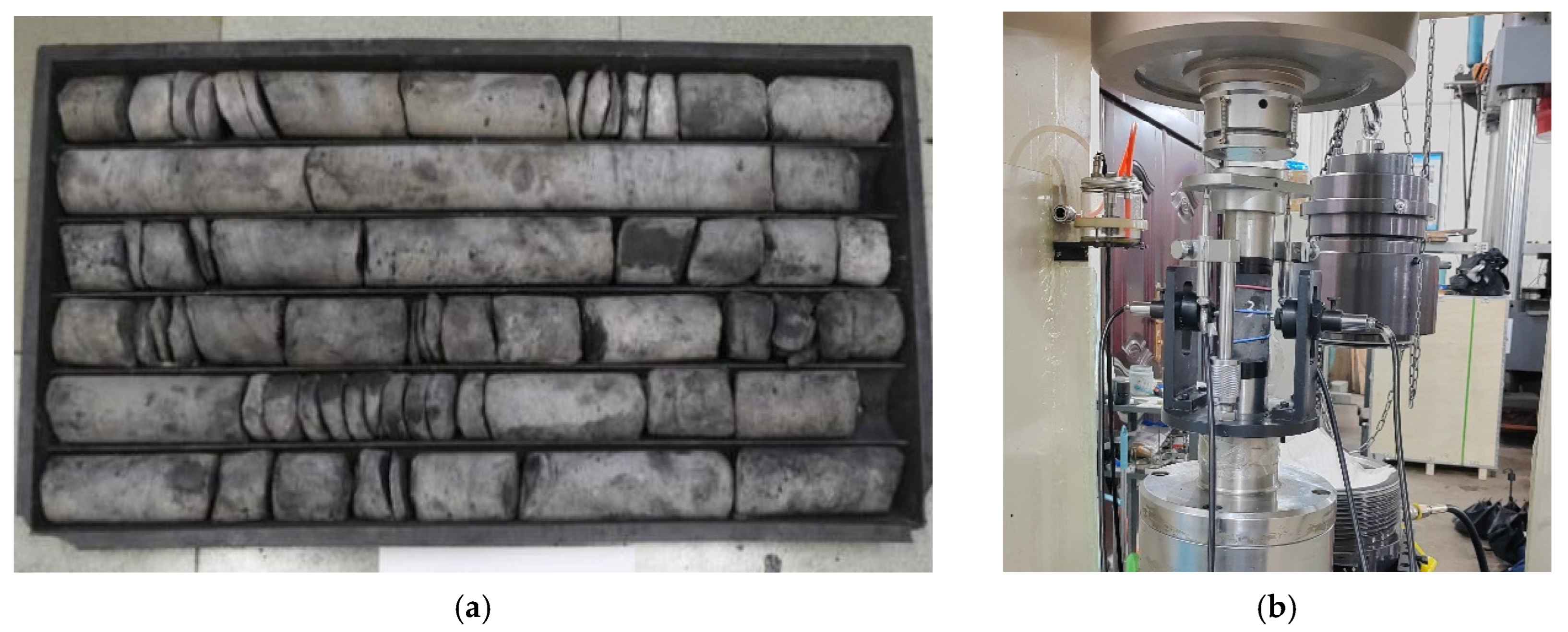
The calculated roof treatment height for the 2404 working face is 50.13 m. To validate this height, core samples were obtained from the 2404 transportation tunnel roof via in situ drilling (representative samples in Figure 6a). Lithological properties align with the geological column (Figure 2), showing distinct stratigraphic variation: 0–17 m interval: dominantly fractured medium-fine sandstone; 17–55 m interval: primarily intact medium-coarse sandstone. Meanwhile, the 2404 roof core was processed into standard cylindrical rock samples (50 mm in diameter × 100 mm), and the conventional mechanical parameters of the rock mass were tested in the Rock Mechanics Laboratory of Xi’an University of Science and Technology. The RMT-201 electro-hydraulic (Wuhan Institute of Rock and Soil Mechanics, Chinese Academy of Sciences, Wuhan, China) servo rock mechanics test system was mainly used, as shown in Figure 6b. During the test, the specimens were placed into the experimental equipment according to the operation steps, loaded at an axial displacement rate of 0.001 mm/s, and continuously loaded at the above loading speed until the specimens were damaged. Based on the failure load obtained from the test, the uniaxial compressive strength of the specimen is:
R c = P F × 10
The formula represents the uniaxial compressive strength of the specimen, in MPa. For the failure load of the specimen, kN is the initial pressure-bearing area of the specimen, cm2. The compressive strength of the specimens was calculated and determined by using the arithmetic mean. The uniaxial compressive results of the rock samples were statistically presented in Table 2. It can be seen from Table 2 that the rock sample strength of the fine sandstone section in the roof slab is relatively low, with an average uniaxial compressive strength of 26.30 MPa and a confidence interval of 26.30 ± 2.83. The rock sample specimens of the medium and coarse sandstone section have relatively high strength. The average uniaxial compressive strength of the saturated rock samples is 41.92 MPa, and the confidence interval is 41.92 ± 2.69. It also has good homogeneity, and its mechanical properties are relatively stable.

2.2.2. Geological Parameters

Based on overburden characteristics of the 2404 working face, key stratum analysis for the 4-2 coal seam roof (Table 3) identifies a monolithic rock layer >15 m thick above the seam.
When mined, this thick stratum induces dual hazards: bending elastic energy accumulation in coal beneath suspended roof sections; impact loading from sudden fracture events, creating conditions conducive to dynamic failure. Analysis confirms the following: main controlling stratum: 38.05 m medium-coarse sandstone (vertical height: 55.65 m); subordinate key stratum: 16.30 m medium-fine sandstone. To mitigate these risks, hydraulic fracturing holes were designed in the 2404 transport tunnel targeting the 56 m vertical height horizon. This strategically weakens high-level key strata, attenuating stress transfer through the roof.

2.3. Scheme Design

2.3.1. Drilling Parameter Design

The construction section length of the 2404 working face transportation tunnel is 200 m. To ensure fracturing effectiveness, the design drill hole spacing is 5 m, the drill hole length is 60 m, the inclination angle is 80°, the angle between the drill hole and the tunnel alignment is 90°, and the hole mouth protection distance is 15 m. The drill hole construction parameters are shown in Table 4. The vertical height of this design parameter is 59 m, which ensures that the high-level critical layer is relieved of pressure. The plan view of the borehole layout is shown in Figure 7a, and the sectional view of the borehole layout is shown in Figure 7b.

2.3.2. Segmented Hydraulic Fracturing Process

The hydraulic fracturing system includes main processes, such as well sealing, high-pressure water fracturing, pressure maintenance water injection, and fracturing monitoring. Segmented hydraulic fracturing operations begin with the installation and commissioning of equipment. Once everything is ready, the water injection steel pipe is connected to push the plugging device to the predetermined fracturing location. The segmented backward fracturing method is then used to fracture the formation from the bottom of the wellbore outward in sequence. Pressurize the plugging device to 12–16 MPa, observe the pressure gauge, and ensure that the plugging device is functioning normally. If the pressure drops, exit the inspection. Start the high-pressure water pump, gradually increase the pressure until the pre-fracture cracks open and enter the pressure maintenance stage, while recording the data from the pump pressure gauge and flow meter to ensure that the roof rock layer is sufficiently softened. The pressure maintenance time should be no less than 30 min. After fracturing is complete, the plugging device is depressurized and retracted to the next fracturing position.
For single-stage fracturing water consumption, the BZW80/63 high-pressure (China Huakang Heavy Industry Co., Ltd., Jining, China) water pump is used for pressure injection. During the pressure-holding stage of single-stage fracturing (pressure-holding time ≥ 30 min), continuous water injection is required. Based on the on-site flowmeter data, the single-stage fracturing water consumption is stably maintained at 4.0 to 4.5 m3. For the total water consumption per hole, the designed number of fracturing sections for a single hole is 15. The total water consumption of a single hole is the product of the water consumption of a single section and the number of fracturing sections, that is, 60 to 67.5 cubic meters. A total of 40 pressure cracking holes are arranged in the construction section of the 2404 transportation tunnel, with a total water consumption of approximately 2400–2700 cubic meters. Water is supplied in batches through underground water storage tanks on site to ensure a continuous and stable water volume.

2.3.3. Construction Period and Safety Preparations

During the overall construction period, the 40 pressure cracking holes in the 2404 transportation tunnel are constructed in parallel in two groups (each group consists of 2 ZDY1900L drilling RIGS (Xi’an Research Institute of China Coal Technology & Engineering Group Co., Ltd., Xi’an, China) and 1 BZW80/63 high-pressure water pump (China Huakang Heavy Industry Co., Ltd., Jining, China)). Each group can complete an average of 2 pressure cracking holes per day. The overall construction period is approximately 20 days, which is in line with the mining progress of the 2404 working face. There is no issue of “fracturing lag affecting recovery”.
Construction Safety Preparation: Prior to commencing construction, geological risk assessments and equipment safety inspections must be conducted. Construction activities should only begin once the gas concentration has been confirmed to be below 0.5%. The pressure gauge of the high-pressure water pump must be inspected to ensure that the equipment does not operate with existing faults. During the construction process, designated personnel should continuously monitor the pressure of the high-pressure water pump in real time and inspect the sealing performance of the hole-sealing device to prevent water leakage caused by high pressure, which could lead to seepage on the tunnel roof. For personnel protection, all construction workers must wear protective gear designed to withstand high-pressure water impact. A protective barrier should be installed within a 5-m radius in front of the borehole to prevent injuries from flying rock debris. Unauthorized personnel must be strictly prohibited from entering the fracturing zone. Upon completion of construction, appropriate safety finishing procedures should be implemented. Borehole backwater must be promptly drained through the tunnel drainage system to prevent water accumulation that could hinder tunnel passage. Within 24 h after fracturing, an inspection borehole should be drilled to assess the tunnel roof for any secondary fracturing. If large-scale hole wall collapse is detected, immediate reinforcement using anchor cables should be carried out to ensure structural stability and the safety of subsequent mining operations.

2.4. On-Site Construction Process

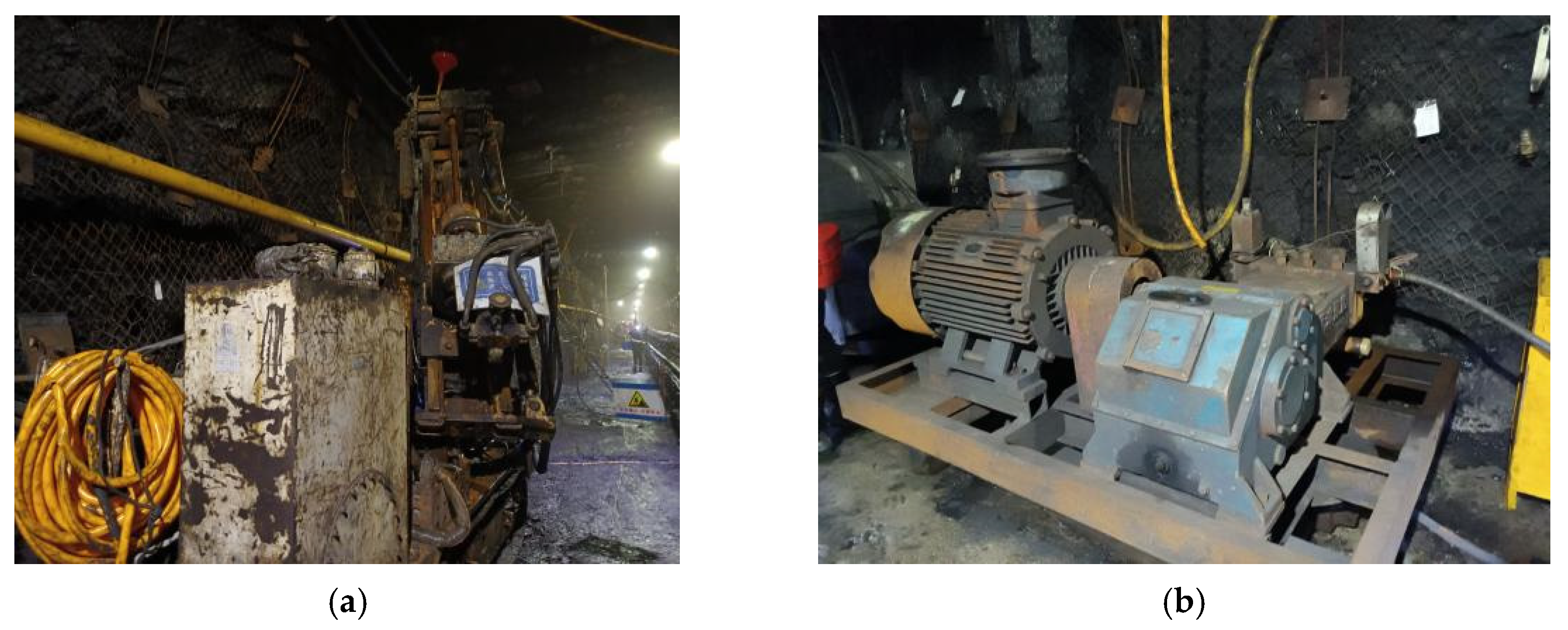
First, to ensure the safety and stability of the transport roadway during the hydraulic fracturing pressure-relief process of the hard roof, a single hydraulic support is temporarily installed in the 2404 transport roadway. The drilling operation employs a ZDY1900L underground tunnel crawler drilling rig (Figure 8a), utilizing a 42 mm drill pipe in conjunction with a 56 mm composite drill bit. Each drill pipe segment measures 1.5 m in length, and the total drilling depth reaches 60 m. Upon completion of the drilling process, the fracturing equipment is installed and tested, and the water injection steel pipe is connected to advance the hole-sealing device to the first fracturing position. Subsequently, water injection fracturing is conducted using a BZW80/63 high-pressure water pump (Figure 8b). After fracturing is completed at each section, the corresponding length of the water injection steel pipe is removed, and the hole-sealing device is repositioned to the next fracturing point. Fracturing operations are carried out at intervals of 3 m, with the process repeated until the predetermined number of fracturing sections is achieved. The construction follows the principle of “drill one and fracture one,” which effectively preserves the original in situ stress environment, minimizes stress interference and crack deviation caused by multi-stage drilling, ensures crack propagation in the intended direction, and partially reduces the uncertainty associated with the overall construction timeline. Finally, upon completion of the hydraulic fracturing operations, the individual hydraulic supports are gradually removed, and a comprehensive monitoring section is established within the fractured zone to enable real-time monitoring of the effectiveness of the integrated surrounding rock control technology in the dynamic pressure roadway.

3. Fracturing Effect Analysis

3.1. Pressure Curve Analysis

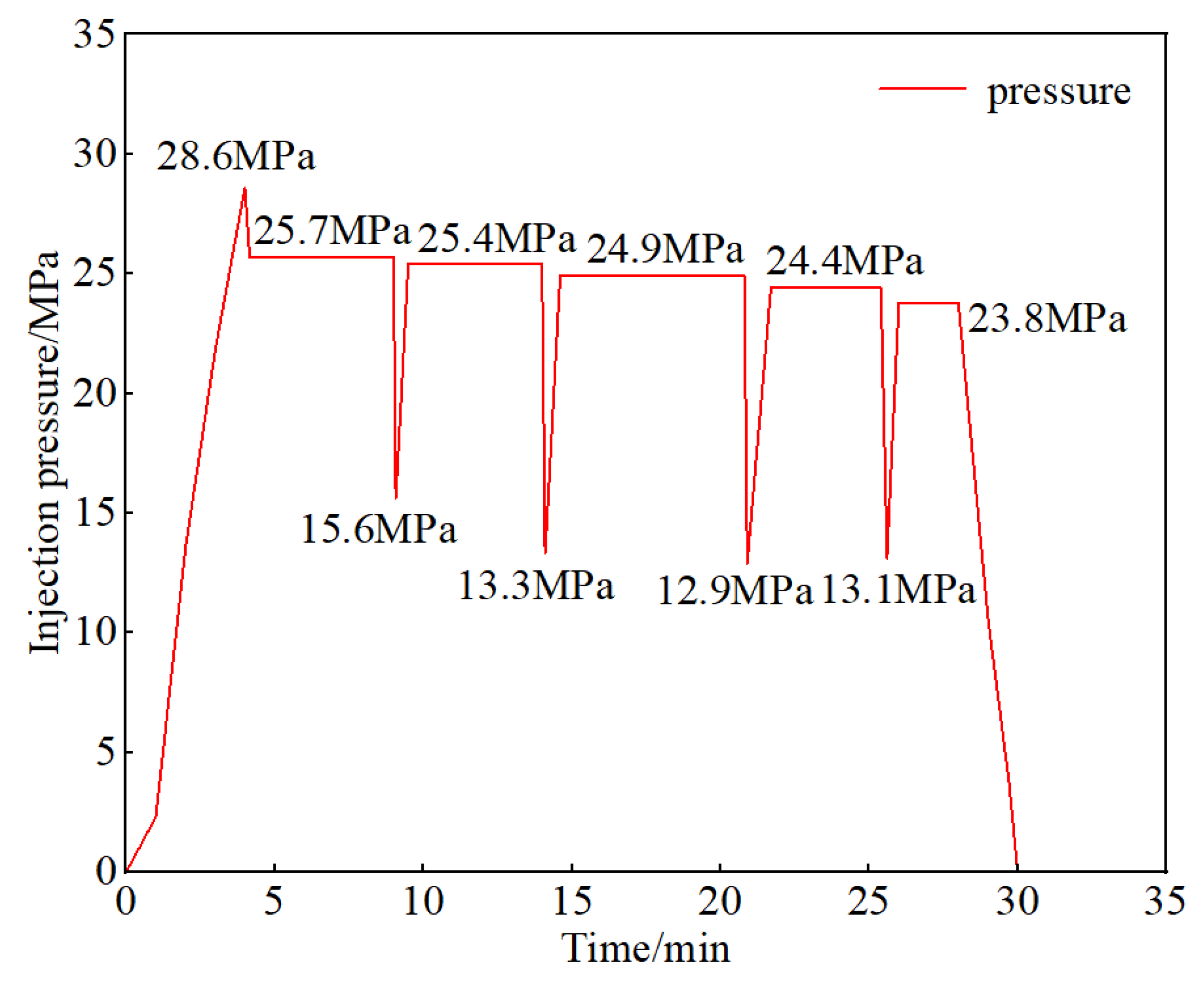
During the fracturing process, changes in injection pressure are recorded using a water pressure monitor. Based on the water pressure characteristic curve, the initial fracture pressure and expansion pressure can be accurately determined, and the expansion of the overlying rock layer fractures can be effectively reflected. The hydraulic fracturing water pressure characteristic curve during construction is shown in Figure 9.
Analysis of Figure 9 shows that when the injection pressure reaches 28.6 MPa, cracks begin to form in the rock mass, causing a slight drop in injection pressure. In addition, hydraulic fracturing causes significant fracturing and softening effects on rock formations. The initial peak pressure has already caused rock fractures and weakened the strength of rock formations within a certain range of the fracturing area, reducing the fracture toughness of the rock formations. This causes further expansion and extension of cracks after maintaining pressure (25.7 MPa) for a certain period of time, resulting in a significant reduction in pressure. Subsequent water injection fracturing processes are affected by the damage caused by previous fracturing, further reducing fracture toughness. Under repeated water injection fracturing, cracks continue to expand and rock strength continues to weaken, causing pressure to gradually decrease during subsequent pressure maintenance stages until cracks extend and connect to adjacent boreholes. After the fracturing operation is completed, the pressure rapidly drops to 0 MPa. During the fracturing process, there were five distinct pressure drops, indicating the formation of significant fractures within the rock formation. The pressure after recovery was lower than that during the previous pressure maintenance phase, suggesting that the strength of the target rock layer is gradually weakening, thereby achieving the desired fracturing effect.

3.2. Analysis of Support Resistance in the Working Face

We conducted a comparative analysis of mine pressure data within a 100-m radius of the initial square and hydraulic fracturing zones at the 2404 working face. Figure 10 depicts changes in hydraulic support pressure. Representative supports from the upper, middle, and lower measurement zones were selected. Using working face advancement distance as the horizontal coordinate and hydraulic support working resistance as the vertical coordinate, we defined pressure based on the mean working resistance plus twice its standard deviation. Table 5 summarizes working face pressure conditions, while Table 6 compares mine pressure characteristics between unfractured and fractured areas.
Analysis reveals that in unfractured areas, the average initial pressure step distance is 33.3 m, with cyclic pressure step distances ranging from 22.7 to 30.7 m (mean: 27 m). During pressure application, support working resistance varies between 8160.84 and 9236.05 kN (mean: 8873.57 kN). In contrast, fractured areas exhibit cyclic pressure step distances of 14.7–24 m (mean: 17.7 m) and support working resistance of 7068.06–7404.30 kN (mean: 7253.07 kN).
Unfractured areas show larger cyclic pressure step distances, whereas fractured areas demonstrate significantly reduced cyclic pressure step distances and mine pressure intensity. Compared to unfractured conditions, fractured areas exhibit 34% smaller cyclic pressure step distances and 18% lower support working resistance. This indicates that hydraulic fracturing reduces the rock layer’s bearing capacity and overall strength, validating its effectiveness in roof weakening.

3.3. Coal Pillar Stress Monitoring Analysis

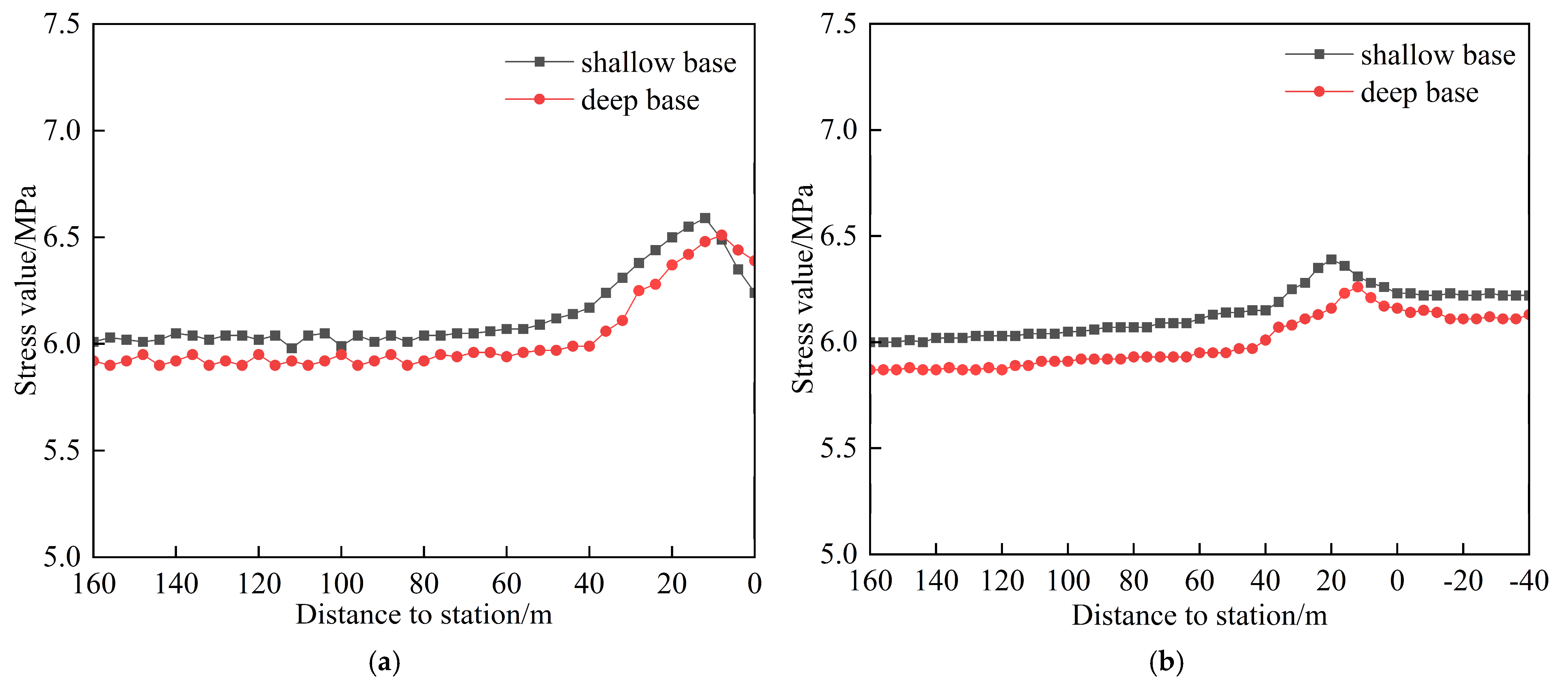
Coal pillar stress monitoring effectively reflects the impact of mining disturbances from the working face on adjacent tunnels. Stress sensors were installed on the coal pillar sides of both the 2404 transportation tunnel and the south wing main tunnel. Figure 11a,b depict the resulting coal pillar stress change curves. As the working face advanced toward the monitoring stations, coal pillar stress progressed through three distinct phases:
At the pre-mining stress stage, there was minimal stress variation. At the advance influence stage, stress increased, peaked, and then decreased. At the post-mining stabilization stage, stress plateaued at a new equilibrium. During the advance influence stage, monitored stress changes were notably attenuated. This attenuation indicates that hydraulic fracturing disrupted stress transmission pathways within key rock layers, reducing both static stress concentrations from support pressure and dynamic vibration loads induced by roof failure. Collectively, these mechanisms enhance the long-term safety and stability of the south wing main tunnel.

3.4. Analysis of Drillhole Inspection Results

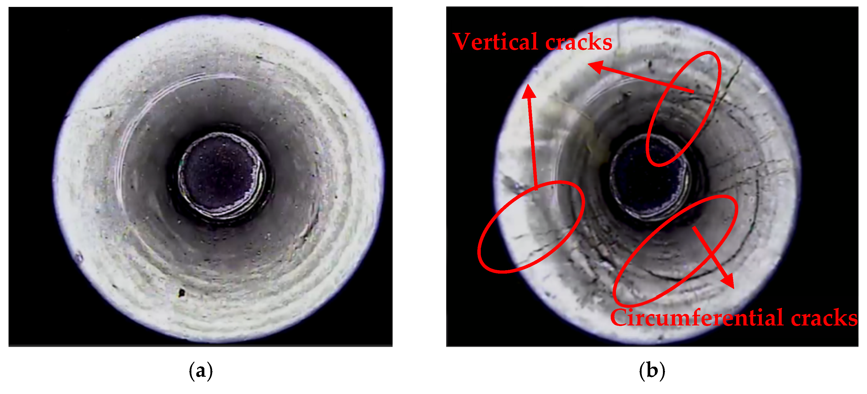
Drillhole inspection enables direct observation of fracture development on borehole walls before and after hydraulic fracturing. As shown in Figure 12, pre-intervention (Figure 12a), borehole walls exhibited no visible cracks, confirming intact rock with high structural integrity. Post-fracturing (Figure 12b), numerous microcracks formed, predominantly longitudinal with minor circumferential fractures.
This fracture distribution aligns with theoretical models: Hydraulic fracturing fluid was injected axially along boreholes drilled perpendicular to rock bedding. Consequently, induced tensile stresses propagated fractures parallel to the borehole axis consistent with findings in literature [31,32]. The increased fracture density and reduced borehole wall integrity demonstrate effective rock mass preconditioning, confirming hydraulic fracturing successfully enhanced structural discontinuities.

3.5. Analysis of Water Flow from Adjacent Drill Holes

During hydraulic fracturing, fracture penetration extent can be assessed by monitoring water flow from anchor cables near the fracturing hole and adjacent drill holes (Figure 13). As shown in Figure 13, injection pressure increases during operations until reaching 28.6 MPa, where a slight pressure drop occurs (Figure 9). This pressure decrease indicates initial rock fracturing. Concurrently, water seepage emerges around the fracturing hole. With continued fracturing, water seepage or distinct flow develops on anchor cables and adjacent drill holes. This demonstrates that fractures have propagated within the formation, reaching both the anchor cables and nearby holes, confirming effective fracturing.

3.6. Hydraulic Fracturing PFC Numerical Simulation Analysis

(1)
Modeling and Parameter Selection
Based on coal bed conditions in the study area, we used PFC 2D numerical simulation software (version 5.0) to validate the hydraulic fracturing top-cutting and unloading parameter design for the 2404 longwall face transportation roadway. Figure 14 illustrates the simulation setup. The model comprises two components: longitudinal section model (100 m × 100 m): boundary particle movement was controlled via servo mechanisms to apply loads, simulating initial ground stress and hydraulic fracturing crack propagation; cross-section model (430 m × 100 m): after achieving initial equilibrium, the working face was excavated and subjected to fracturing.
(2)
Analysis of results
Figure 15 shows that at a 5 m drilling spacing, hydraulically induced cracks (red) form extensively around boreholes. These cracks exhibit continuous, uniform distribution patterns, indicating effective fracture independence and network connectivity. This spacing optimizes fracturing outcomes by ensuring sufficient fracture propagation and network connectivity while preventing resource waste and cost overruns associated with excessively dense or sparse borehole arrangements. Considering fracturing effectiveness and economic efficiency, the 5 m spacing constitutes an engineering-viable solution with favorable applicability and cost-effectiveness.
Figure 16 reveals that following working face excavation, the resistant-to-caving roof strata form a large-span cantilever structure above the goaf. This configuration induces significant displacement in overlying strata while restricting downward stress release. Consequently, stress migrates laterally and concentrates notably within the coal pillar and main roadway zones. This coupled stress-displacement response not only increases surrounding rock failure risk but also enables energy accumulation conducive to rockburst events.
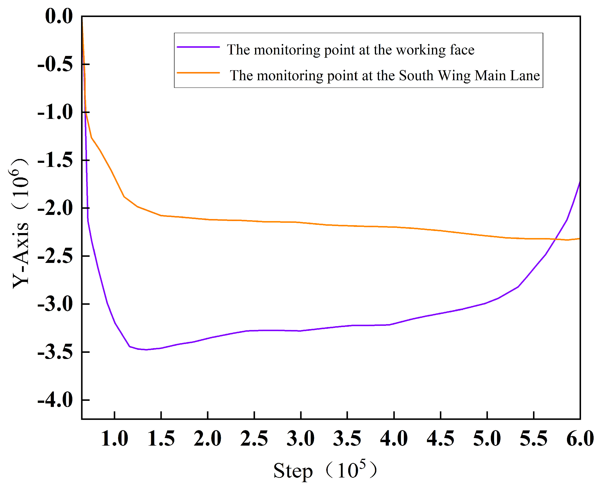
Following working face excavation, hydraulic fracturing pressure relief was simulated on the hard roof (Figure 17). Figure 18 displays monitored stress changes in the surrounding rock: orange curve: stress evolution at the south gate road coal pillar monitoring point; purple curve: stress evolution at the working face coal pillar monitoring point. During excavation, both coal pillars exhibit increasing stress, with the working face pillar showing greater magnitude changes. Subsequent hydraulic top-cutting fracturing immediately stabilized stress at the south gate road pillar. This indicates the working face disturbances no longer significantly affect this zone, demonstrating that hydraulic fracturing effectively mitigates dynamic stress transfer to pillar lateral support structures. Consequently, fracturing contributes to maintaining south gate road surrounding rock stability.

4. Fatigue Deformation Constitutive Model of Double-Fractured Sandstone After Freeze–Thaw Cycles

4.1. The Establishment of Constitutive Models

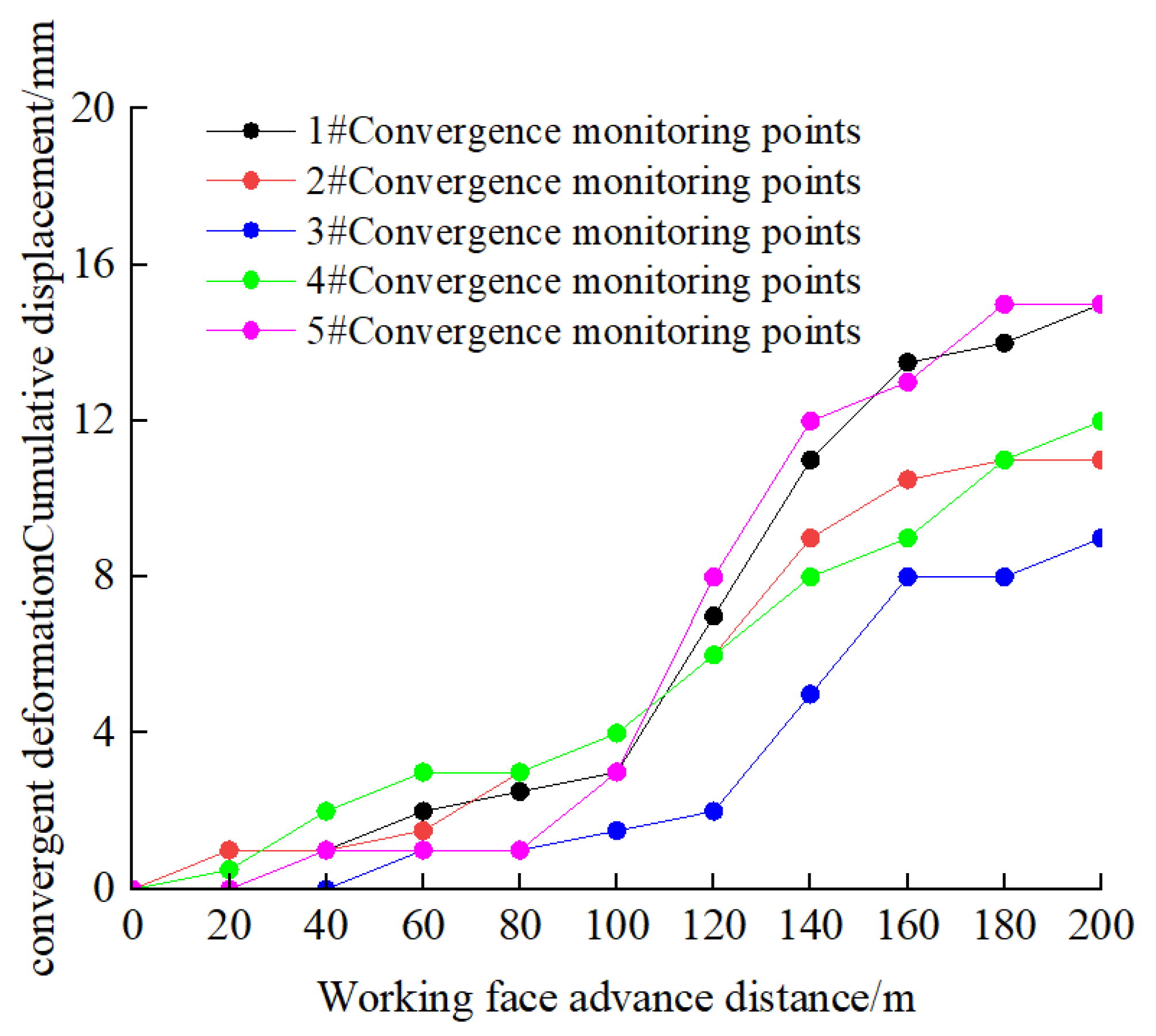
Figure 19 presents cumulative displacement curves for convergence deformation at monitoring points 1#~5# in the south gate road. All curves exhibit similar trends and magnitudes. Key observations include the following: initial stability (0~80 m advance): negligible displacement indicates stable tunnel walls; accelerated deformation (80~140 m advance): displacement increases progressively, peaking at 15 mm between 100 and 140 m; post-intervention stabilization (>140 m advance): displacement decreases substantially and stabilizes.
This stabilization confirms the efficacy of hydraulic fracturing in the 2404 transport tunnel. By disrupting stress transmission pathways between critical strata, the intervention effectively mitigated convergence deformation in the south gate road.

4.2. Analysis of Roof Separation Monitoring Results

Figure 20 displays cumulative displacement curves for monitoring points #1~#5 in the south gate road. Both curves exhibit consistent fluctuation trends and amplitudes. Key observations reveal the following: stable phase (<80 m advance): negligible roof displacement indicates structural stability, with minimal borehole delamination observed at depth; accelerated deformation (100–140 m advance): significant roof displacement increase, maximum displacement (5 mm) occurs at deep measurement points, rapid deformation changes between 3 and 8 m depth; stabilization phase (>140 m advance): displacement substantially decreases and plateaus.
This response confirms that hydraulic fracturing in the 2404 transport tunnel successfully disrupted critical interlayer stress transmission pathways, effectively mitigating roof displacement and ensuring south gate road stability. The intervention demonstrates significant pressure relief, contributing to long-term tunnel integrity.

4.3. Analysis of the Current Status of the South Wing Main Tunnel

Large-scale underground hydraulic fracturing involves multiple potential environmental and safety impacts. From an environmental perspective, the process requires significant water consumption, such as the 2400 to 2700 cubic meters used in the 2404 transportation tunnel project, which may lead to local fluctuations in groundwater levels. Improper discharge of backflow water containing rock powder can cause blockages in tunnel drainage systems and potentially result in cross-aquifer contamination through induced fissures. Regarding safety, the concurrent operation of multiple high-pressure systems poses risks, as inadequate pipeline sealing may lead to high-pressure water leakage, endangering personnel. Additionally, large-scale operations may create blind spots in gas monitoring, increasing the likelihood of gas accumulation. Furthermore, excessive fissure expansion may induce secondary roof fracturing, compromising the integrity and stability of support structures.
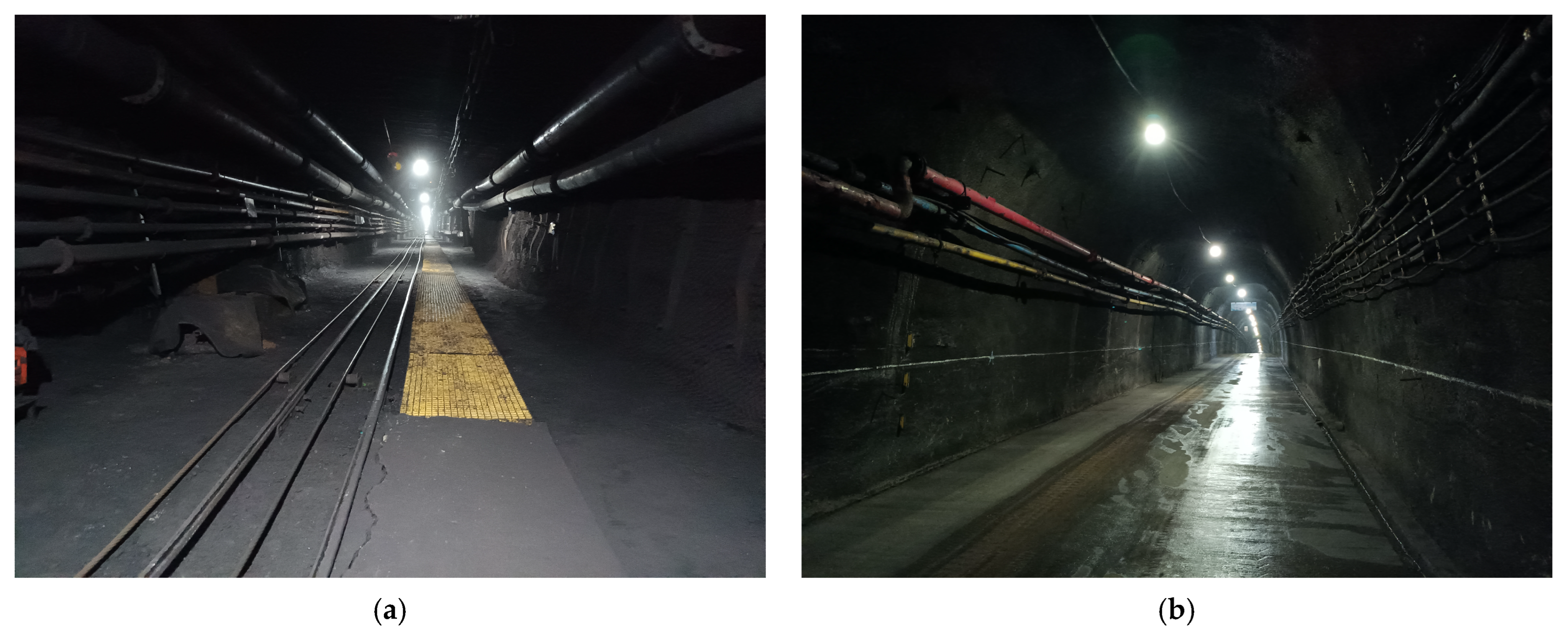
According to the on-site investigation results, the on-site situation of the south wing main tunnel after pressure relief is shown in Figure 21. In the area of the 2404 transportation tunnel where pressure-relief treatment has not been implemented, the mining pressure in the south wing main tunnel is relatively obvious. Compared with the previous text, the bottom drum of the undepressurized section is more serious, and the bottom plate of some sections has cracked, and the side of the tunnel has deformed and cracked. In particular, the surrounding rock of the roadway on the coal pillar side near the south wing main tunnel has undergone severe convergence and deformation.
It can be seen that the south wing main tunnel is significantly affected by the mining disturbance of the 2404 fully mechanized face. The superimposed effect of the dynamic stress generated by mining and the lateral support stress has led to deformation and failure in some sections of the south wing main tunnel. In the pressure-relief treatment area of the 2404 transportation roadway, the deformation of the bottom drum of the south wing main roadway is relatively small, and no deformation or cracking of the surrounding rock has occurred. This indicates that hydraulic fracturing pressure relief can effectively reduce the stress concentration effect of the coal pillar, weaken the overall bearing capacity of the rock mass through the induction and expansion of fractures, and thereby block the stress transmission path.
The influence of repeated dynamic disturbances during mining in the 2404 fully mechanized caving face on the stability of the surrounding rock in the southern wing main tunnel has been reduced. Under the action of fracturing, the fracture network inside the coal pillar gradually develops, reducing the stress level in the high-stress area and redistributing the local stress to the surrounding areas, thereby alleviating the stress concentration problem of the coal pillar and improving the safety of the mine.

5. Conclusions

(1)
The south wing main tunnel of a certain mine in the Jiaoping Mining Area is a deeply buried tunnel that has been significantly affected by the intense mining activities of the 2404 working face. The roof of the 2404 working face consists of thick, hard rock layers that are difficult to fracture, making it prone to forming a hanging roof. This increases the stress and deformation of the coal pillar, affecting the stability of the surrounding rock and the support structure of the south wing main drift. The method of cutting through the hard roof of the 2404 working face’s transportation drift to relieve pressure was adopted to reduce the impact of the mining pressure from the 2404 working face on the deformation of the surrounding rock in the south wing main drift, providing technical support for the safe construction of the south wing main drift.
(2)
The critical roof strata elevation for the 2404 working face hydraulic fracturing top-cutting operation, determined through theoretical analysis, is 50.13 m. Physical and mechanical properties of each strata elevation were determined through on-site core sampling tests. The roof caving stress relief plan for the 2404 transportation roadway was completed. The design drill hole length is 60 m, with an inclination angle of 80°, an angle of 90° along the roadway direction, a fracturing vertical height of 59 m, a drill hole spacing of 5 m, and a segmented hydraulic fracturing stress relief mode.
(3)
Using a multi-disciplinary approach to analyze the effectiveness of hydraulic fracturing, the results of borehole inspections and pressure curve analysis revealed significant longitudinal fractures within the borehole walls. During fracturing, the maximum pressure reached 28.6 MPa, with five distinct pressure drops indicating fracturing. Additionally, during the fracturing process, both adjacent boreholes and anchor cables exhibited noticeable water outflow, indicating the formation of interconnected fractures between boreholes. Following fracturing, the pressure step distance decreased by 34%, and the support working resistance decreased by 18%. The pressure step distance, pressure range, and support working resistance during the cycle all decreased significantly. During coal extraction, the stress changes in the coal pillar were relatively small, the support structure of the south wing main tunnel remained intact, and mine pressure was not significantly evident. It is explained that hydraulic fracturing weakened the hard roof, significantly reducing its strength and integrity, and severed the stress transfer path of the key rock layer, effectively ensuring the long-term safe use of the south wing main tunnel.
(4)
The pressure-relief effect shows that the cumulative displacement of the surrounding rock and the change in the roof separation in the pressure-relief area of the south wing main tunnel are relatively small. The surrounding rock of the main tunnel shows no significant deformation, and the support structure remains intact. The surrounding rock of the south wing main tunnel is basically in a stable state, indicating that the hydraulic fracturing and roof cutting pressure-relief effect is good, thereby reducing the impact of mining dynamic pressure disturbances on the deformation of the south wing main tunnel.

Author Contributions

Conceptualization, K.S. and C.S.; methodology, J.R. and K.S.; validation, C.S.; formal analysis, K.S.; investigation, C.S.; resources, J.R. and K.S.; data curation, C.S.; writing—original draft preparation, K.S., J.R. and C.S.; writing—review and editing, K.S. and J.R.; funding acquisition, J.R. All authors have read and agreed to the published version of the manuscript.

Funding

This work has been supported by the National Natural Science Foundation of China (11872299, 12072259, 42377187) and the Shaanxi Province Natural Science Basic Research Program-Shaanxi Coal Joint Fund (2019JLP-01).

Institutional Review Board Statement

Not applicable.

Informed Consent Statement

Not applicable.

Data Availability Statement

The data presented in this study are available on request from the corresponding author.

Acknowledgments

Thanks to the on-site assistance provided by Shaanxi Coal Tongchuan Company, especially Yuan Hao and Yue Dong for determining the on-site plan of the article and providing conditions such as data collection.

Conflicts of Interest

The authors declare no conflicts of interest.

References

  1. Liu, J.; Liang, Y.; Cheng, K.; Wang, M.; Gao, M.; Liu, Z. Research on the construction of coal mine safety production technology management system. Coal Mine Saf. 2021, 52, 256–260. [Google Scholar] [CrossRef]
  2. Wang, G.; Pan, Y.; Zhao, S.; Pang, Y.; He, Y.; Wei, W. How to realize safe-efficient-intelligent mining of rock burst coal seam. Coal Sci. Technol. 2024, 52, 1–14. [Google Scholar] [CrossRef]
  3. Yuan, L. Theory and technology considerations on high-quality development of coal main energy security in China. Bull. Chin. Acad. Sci. 2023, 38, 11–22. [Google Scholar] [CrossRef]
  4. Zhang, W. Research on dynamic pressure behavior and control technology of goaf roadway in extra-thick coal seam. China Min. Mag. 2023, 32, 126–131. [Google Scholar] [CrossRef]
  5. Liu, G.; Mu, Z.; Chen, J.; Yang, J.; Cao, J. Rock burst risk in an island longwall coal face by stress field. Geosci. J. 2018, 22, 609–622. [Google Scholar] [CrossRef]
  6. He, Z.-L.; Lu, C.-P.; Zhang, X.-F.; Guo, Y.; Meng, Z.-H.; Xia, L. Numerical and field investigations of rockburst mechanisms triggered by thick-hard roof fracturing. Rock Mech. Rock Eng. 2022, 55, 6863–6886. [Google Scholar] [CrossRef]
  7. Kang, J.; Jian, K.; Fu, X.; Shen, J.; Wang, Y. Study on hydraulic fracturing fracture propagation in steeply inclined coal reservoirs. Coal Mine Saf. 2024, 55, 49–60. [Google Scholar] [CrossRef]
  8. Kang, H.; Jiang, P.; Feng, Y.; Zhao, K. Destressing technology for rock around coal mine roadways and its applications. Coal Sci. Technol. 2022, 50, 1–15. [Google Scholar] [CrossRef]
  9. Hou, C.; Wang, X.; Bai, J.; Meng, N.; Wu, W. Basic theory and technology study of stability control for surrounding rock in deep roadway. J. China Univ. Min. Technol. 2021, 50, 1–12. [Google Scholar]
  10. Yao, A.; Wu, Z.; Yang, D.; Shao, H. Prevention and control technology of roadway bottom drum based on roof cutting pressure relief method. Coal Mine Saf. 2017, 48, 92–94+98. [Google Scholar]
  11. Tian, Z.; Hu, Z.; Zhang, C.; Zhang, X.; Zhong, L.; Zhang, K.; Sun, N. Study on failure mechanism and control technology of extra-thick coal seam roadway under dynamic load disturbance. Coal Technol. 2024, 43, 26–31. [Google Scholar]
  12. Li, J.; Wu, Z.; Zhang, W.; Ma, N.; Guo, S. Study on Shape Characteristics of Plastic Zone in Heterogeneous Roadway-Surrounding Rock. Sustainability 2022, 14, 9480. [Google Scholar] [CrossRef]
  13. Xi, P.; Zhu, D.; Huo, Y.; Xin, C. Numerical investigation of the failure mechanism and countermeasures of the roadway surrounding rockmass within deep soft rock. Int. J. Multiscale Comput. Eng. 2022, 18, 1–11. [Google Scholar] [CrossRef]
  14. Meng, Q.; Han, L.; Xiao, Y.; Li, H.; Wen, S.; Zhang, J. Numerical simulation study of the failure evolution process and failure mode of surrounding rock in deep soft rock roadways. Int. J. Min. Sci. Technol. 2016, 26, 209–221. [Google Scholar] [CrossRef]
  15. Tian, M.; Han, L.; Meng, Q.; Ma, C.; Zong, Y.; Mao, P. Physical model experiment of surrounding rock failure mechanism for the roadway under deviatoric pressure form mining disturbance. KSCE J. Civ. Eng. 2020, 24, 1103–1115. [Google Scholar] [CrossRef]
  16. Yin, S.; Zheng, X.; Wang, E.; Kang, Q.; Zhang, X. Non-uniform failure and differential pressure relief technology of roadway under irregular goafs in deep close-distance coal seams. Sci. Rep. 2023, 13, 18527. [Google Scholar] [CrossRef]
  17. Liang, Y.; Jin, J.; Zha, W.; Xu, T.; Cheng, W. Study on the evolution law of the ‘Butterfly-type’ plastic zone in the surrounding rock of deep dynamic pressure roadway. Sci. Rep. 2025, 15, 2731. [Google Scholar] [CrossRef]
  18. Du, X. Research progress and prospect of borehole pressure relief technology to prevent rock burst. Coal Mine Saf. 2024, 55, 28–40. [Google Scholar]
  19. Sun, S.; Li, W.; Zhang, J.; Chen, D.; Zhao, J.; Zheng, K.; Long, W.; Wang, C.; Jia, B.; Du, T.; et al. Research progress and development trend of staged hydraulic fracturing technology in long-borehole underground coal mine. Coal Geol. Explor. 2022, 50, 1–15. [Google Scholar] [CrossRef]
  20. Niu, T. Study on surrounding rock control technology for weakened hard roof of stope by staged hydraulic fracturing. Coal Sci. Technol. 2022, 50, 50–59. [Google Scholar]
  21. Cheng, L.; Zhang, Z.; Jiang, P. Research and application of stress field response mechanism based on roof hydraulic fracturing pressure relief. J. Min. Saf. Eng. 2023, 40, 722–729. [Google Scholar]
  22. Gao, F. Influence of hydraulic fracturing of strong roof on mining-induced stress-insight from numerical simulation. J. Min. Strat. Control Eng. 2021, 3, 5–13. [Google Scholar]
  23. Chen, S.; Liu, J.; Li, Y.; Lyu, H. Stress transfer control technology for fracturing weak structural bodies in subgrade dynamic pressure roadways. Coal Sci. Technol. 2024, 52, 106–116. [Google Scholar] [CrossRef]
  24. Zhao, S.; Wang, B.; Su, Z.; Li, S.; Shi, Y.; Sang, X.; Liu, A.; Han, W. Technology and application of long directional drilling hydraulic fracturing for preventing rock burst in thick and hard roof. Saf. Coal Mines 2024, 55, 10–21. [Google Scholar] [CrossRef]
  25. Hu, Q.; Liu, J.; Li, Q.; Zhang, Y.; Song, M.; Sun, W.; Song, J. Study on stress and fracture evolution of sectional hydraulic fracturing of coal seam roof. J. China Univ. Min. Technol. 2023, 52, 1084–1095+1202. [Google Scholar]
  26. Wu, Y.; Kang, H. Pressure relief mechanism and experiment of directional hydraulic fracturing in reused coal pillar roadway. J. China Coal Soc. 2017, 42, 1130–1137. [Google Scholar]
  27. Kang, H.; Feng, Y. Hydraulic fracturing technology and its applications in strata control in underground coal mines. Coal Sci. Technol. 2017, 45, 1–9. [Google Scholar]
  28. Kang, H.; Feng, Y.; Zhang, Z.; Zhao, K.; Wang, P. Hydraulic fracturing technology with directional boreholes for strata control in underground coal mines and its application. Coal Sci. Technol. 2023, 51, 31–44. [Google Scholar] [CrossRef]
  29. Qian, Y.; Li, Q.; Jiang, Z.; Hu, Q.; Wu, W.; Liu, Y.; Li, L.; Zhang, Z.; Yu, C.; Li, W. Microseismic activity characteristics and range evaluation of hydraulic fracturing in coal seam. Gas Sci. Eng. 2024, 122, 205222. [Google Scholar] [CrossRef]
  30. Zhang, N.; Liu, F.; Jiang, L.; Mo, P.; Xiao, J.; Song, Q.; Luo, Y. Coupled THMC model-based prediction of hydraulic fracture geometry and size under self-propping phase-transition fracturing. Int. J. Coal Sci. Technol. 2024, 11, 78. [Google Scholar] [CrossRef]
  31. Wang, Y.; Li, X.; Ji, R.; Cheng, X.; Liu, X.; Zhang, Y.; Sho, M. Research and application of comprehensive surrounding rock control technology for strong dynamic pressure roadway in longwall top-coal caving face. Coal Eng. 2023, 55, 51–57. [Google Scholar]
  32. Wang, C.; Zheng, K.; Wang, H.; Li, Y.; Wang, L.; Yang, D.; Ji, Q.; Cheng, Z. Comprehensive treatment technology of hydraulic fracturing in initial mining of the first mining face under hard roof. Coal Eng. 2023, 55, 63–69. [Google Scholar]
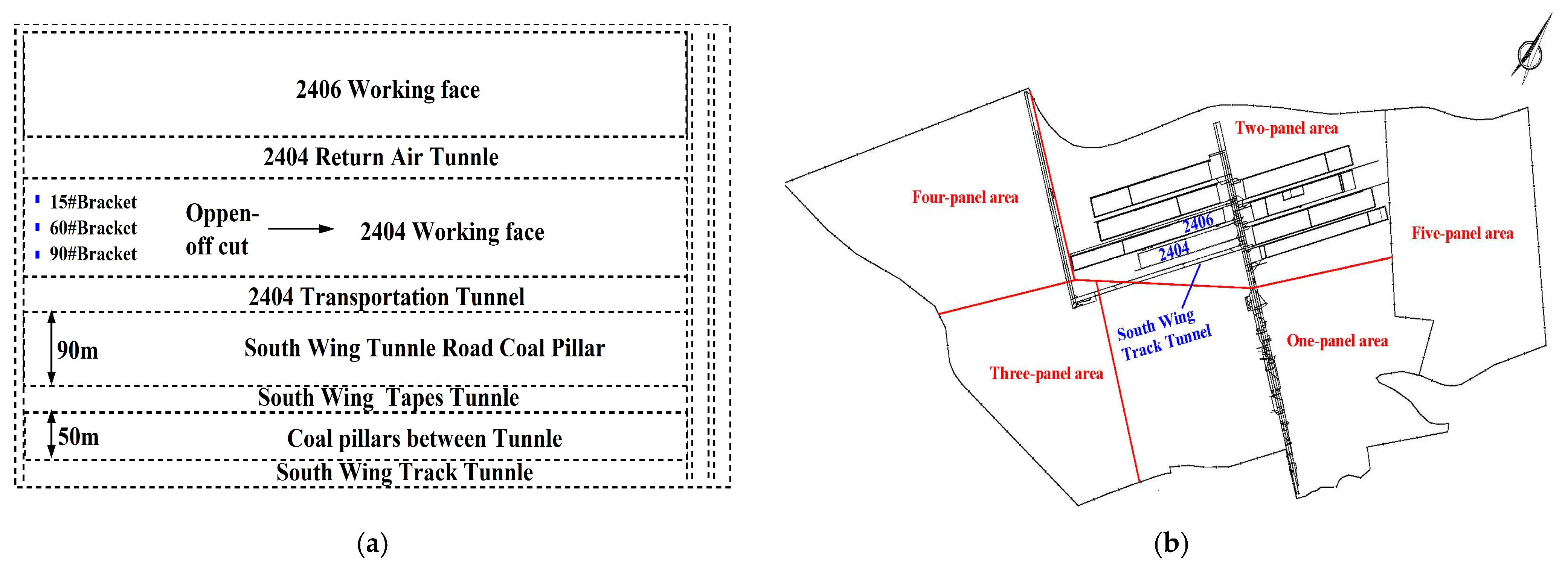
Figure 1. Position relationship diagram of south wing roadway and 2404 working face. (a) Adjacent working faces, (b) comparison of above-ground and underground positions.
Applsci 15 09779 g001
Figure 2. 2404 working face roof and floor overlying rock characteristics.
Applsci 15 09779 g002
Figure 3. On-site situation of south wing alley.
Applsci 15 09779 g003
Figure 4. Variation curve of support working resistance ((a) upper measurement area, (b) central measurement area, (c) lower measurement area).
Applsci 15 09779 g004
Figure 5. Hydraulic fracturing stress transfer principle diagram.
Applsci 15 09779 g005
Figure 6. Test materials and instruments. (a) Drill holes to take core rock samples, (b) rock mechanics test system.
Applsci 15 09779 g006
Figure 7. Drilling layout diagram. (a) Schematic plan of drilling arrangement, (b) schematic diagram of drilling arrangement section.
Applsci 15 09779 g007
Figure 8. Hydraulic fracturing process; (a) borehole construction, (b) high pressure water pumps.
Applsci 15 09779 g008
Figure 9. Hydraulic fracturing water pressure characteristic curve.
Applsci 15 09779 g009
Figure 10. Variation curve of support working resistance ((a) 15# bracket, (b) 65# bracket, (c) 90# bracket).
Applsci 15 09779 g010
Figure 11. The stress change curve of a coal pillar in the 2404 transportation roadway and south wing roadway. (a) 2404 transportation tunnel coal pillar stress, (b) south wing tunnel road coal pillar stress.
Applsci 15 09779 g011
Figure 12. Borehole peep results ((a) crack distribution before fracturing, (b) fracture distribution after fracturing).
Applsci 15 09779 g012
Figure 13. Fracturing construction adjacent drilling and anchor cable water situation.
Applsci 15 09779 g013
Figure 14. Schematic of hydraulic fracturing: (a) cross-sectional model, (b) longitudinal section model.
Applsci 15 09779 g014
Figure 15. Simulation of fracture expansion of drilled hydraulic fracturing.
Applsci 15 09779 g015
Figure 16. Cloud diagram of the displacement of the roof plate after excavation of the working face.
Applsci 15 09779 g016
Figure 17. Schematic diagram of hydraulic fracturing unloading simulation after working face excavation.
Applsci 15 09779 g017
Figure 18. Stress change curve at the monitoring point.
Applsci 15 09779 g018
Figure 19. The cumulative displacement curve of convergence deformation of the two sides of the south wing roadway.
Applsci 15 09779 g019
Figure 20. Cumulative displacement curve of separation layer in the south wing roadway.
Applsci 15 09779 g020
Figure 21. The on-site situation after the pressure relief in the south wing main alley. (a) Transportation roadway, (b) Auxiliary roadway.
Applsci 15 09779 g021
Table 1. Statistics of mining pressure step distance in 2404 working face.
Survey AreaInitial Pressure Step Distance/mFirst Time
Cycle Pressure Step Distance/m
Second Time
Cycle Pressure Step Distance/m
Third Time
Cycle Pressure Step Distance/m
Fourth Time
Cycle Pressure Step Distance/m
Upper3224282832
Middle3228202828
Lower3624203232
Average33.325.322.729.330.7
Table 2. Uniaxial compressive strength test results of rock samples.
Rock Type Uniaxial Compressive Strength
/MPa
Average/MPaRock Type Uniaxial Compressive Strength
/MPa
Average/MPa
Medium-fine Sandstone23.8526.30Medium-coarse Sandstone40.8541.92
25.6041.77
27.7743.29
24.8639.10
29.4144.59
Table 3. 2404 distribution of key strata in overlying strata.
Serial NumberRock TypeAverage Thickness/mKey Layer Height/mRemarks
1Medium-coarse sandstone 38.0555.65Main key layer
2Medium-fine sandstone 16.3017.60Sub-key layer
3Carbonaceous mudstone 1.30
44-2 coal 7.50
Table 4. Drilling construction parameters.
Drill Hole Depth/m Inclination Angle/(°)Tunnel Angle/(°)Drill Hole Spacing/mNumber of Fracturing Segments Per HoleHole Diameter/mm
60809051556
Table 5. Working face pressure statistics.
Support NumberUnfractured Zone Pressure Step Distance/m Fractured Zone Pressure Step Distance/m
Initial PressureFirst Cycle PressureSecond Cycle PressureThird Cycle PressureFourth Cycle Pressure First Cycle PressureSecond Cycle PressureThird Cycle PressureFourth Cycle Pressure
15#322428283212122816
65#322820282812122416
90#3624203232202420
Average33.325.322.729.330.714.7162416
Table 6. Comparison of mine pressure characteristics between unfractured area and fractured area.
ZonePressure Step Distance/mPressure CycleSupport Working Resistance During Pressure Application/kNZonePressure Step Distance/mPressure CycleSupport Working Resistance During Pressure Application/kN
Unfractured zone 25.318160.84Fractured zone14.717219.90
22.729142.3916.027404.30
29.338955.0024.037068.06
30.749236.0516.047320.03
Disclaimer/Publisher’s Note: The statements, opinions and data contained in all publications are solely those of the individual author(s) and contributor(s) and not of MDPI and/or the editor(s). MDPI and/or the editor(s) disclaim responsibility for any injury to people or property resulting from any ideas, methods, instructions or products referred to in the content.