Article

An Experimental Study on the Expansion Rate of Blasting Cracks in Prefabricated Grooved Concrete Under Vertical Stresses

1
Hubei Key Laboratory of Blasting Engineering of Jianghan University, Wuhan 430056, China
2
School of Civil Engineering and Architecture, Anhui University of Science and Technology, Huainan 232001, China
*
Author to whom correspondence should be addressed.
Appl. Sci. 2025, 15(17), 9747; https://doi.org/10.3390/app15179747
Submission received: 25 July 2025 / Revised: 31 August 2025 / Accepted: 2 September 2025 / Published: 4 September 2025

Abstract

With the advancement of deep engineering (e.g., deep resource development, tunnel excavation), the deep rock mass is in a high in situ stress environment, leading to a critical engineering challenge: traditional blasting often causes disordered blast-induced crack propagation (severe deviation from the target direction) and unstable expansion rates, which reduce the directional blasting efficiency, trigger over-excavation/under-excavation, and threaten construction safety. Water jet notching is a promising directional control technique, but its coupling effect with vertical stress (a dominant component of in situ stress) on blasting crack characteristics remains unclear—hindering its application in deep engineering. To address this problem, reveal the law of blasting crack expansion in deep rock, explore the mechanism of controlled blasting for deep rock fractures, and clarify the effect of deep environmental water jet notching on the blasting effect, this study carried out experimental research on the crack extension velocity of the directional blasting of prefabricated grooved concrete under vertical stress (based on the crack extension strain gauge test system and perimeter pressure loading system) and verified the results by numerical simulations. The main conclusions are as follows: (1) Within the experimental test range, with the increase in vertical stress, the deviation of cracks from the prefabricated groove center in the vertical direction gradually decreases, indicating that vertical stress can further guide the direction of the crack extension on the basis of prefabricated grooves. (2) The experimentally measured crack expansion velocity shows a decreasing trend with the increase in the crack expansion length; the average crack expansion velocity is enhanced with the increase in vertical stress, while the change in the crack tip velocity is suppressed as a whole and gradually tends to be flat at approximately 555.6 m/s. (3) Numerical simulation results (using a model replicating the experimental concrete specimens) further verify the accuracy of the experimental results: the increase in vertical stress further guides the vertical crack expansion, enhances the average crack expansion velocity, and slows down the decay of the crack extension velocity. The core value of this research lies in “converting theoretical experimental data into engineering control capabilities.” Its findings can be directly applied to key areas such as deep resource development, tunnel engineering, and water conservancy projects. While ensuring engineering safety, improving efficiency, and reducing costs, it also provides scientific support for engineering construction in complex geological conditions.

1. Introduction

In recent decades, the exploitation of mineral resources (e.g., coal, metal ores) and the construction of underground engineering (e.g., deep tunnels, oil/gas wells) have gradually extended to the deep ground (depth > 1000 m), driven by the depletion of shallow resources. A defining characteristic of deep rock mass is its exposure to high in situ stress (often exceeding 20 MPa), which fundamentally changes the dynamic response of rock under blast loading—one of the most common rock-breaking techniques in deep engineering. However, this high-stress environment poses a critical engineering problem (broad sense): traditional blasting fails to achieve controlled crack propagation. Specifically, with directional disorder cracks tend to deviate from the designed path (e.g., pre-split direction) due to in situ stress, leading to over-excavation (increasing project cost) or under-excavation (compromising structural stability).
Unstable expansion rate: The crack tip velocity fluctuates sharply, reducing blasting efficiency and increasing the risk of sudden rock mass instability (e.g., rock bursts). Limited effect of directional measures: Although water jet grooving (a pre-splitting technique) has shown potential in guiding cracks, its coupling effect with vertical stress (the main component of in situ stress in vertical deep engineering) on crack propagation remains unclear, limiting its application in deep directional blasting. Solving this problem is essential to improving the safety, efficiency, and economy of deep engineering, as it directly addresses the core contradiction between high in situ stress and controlled rock breaking. Scholars have conducted extensive research on blast-induced crack propagation, but critical gaps remain in addressing the aforementioned broad engineering problem.
Water jet grooving has shown good results in pre-splitting and pressure relief in deep environments. However, due to the difficulty in controlling the drilling accuracy of deep holes and the limited range of pressure relief control [1,2,3], it is important to study how water jet grooving can improve blasting results in deep environments, as it provides support for rock directional blasting.
Deep rock blasting fracture and fragmentation is the macroscopic manifestation of the rock medium under the combined action of in situ stress and explosive loads, while the fracture process of deep rock is determined by the development of cracks. The crack development process includes crack initiation, propagation, and unstable failure [4]. The crack propagation velocity is one of the important components of the crack propagation law in rock blasting. The propagation of cracks generated by deep rock explosions is not only related to explosive loads and rock medium properties but also has an inevitable connection with the applied in situ stress. Conducting research on the propagation velocity of rock blast cracks under in situ stress conditions, revealing the propagation patterns of deep rock blast cracks, and exploring the mechanisms of directional fracturing control in deep rock blasting are of significant importance.
Numerous experiments have been conducted to test the crack propagation velocity of blasting. Chen Jingxi [5] used two crack monitoring methods to measure the average crack propagation velocities of gypsum boards, which were 599.5 m/s and 500.74 m/s, respectively; Zhang Zhicheng [6] conducted experiments on crack propagation speeds in different solid media, finding that the average propagation speed in homogeneous rock ranged from 300 to 1000 m/s, with the cement mortar averaging approximately 605 m/s; Li [7] used strain gauge methods to study the dynamic propagation of Type I cracks in rock under directed crack blasting, measuring average crack propagation velocities of 457 m/s for PMMA and 922 m/s for granite; Liu et al. [8] studied crack propagation parameters in four brittle rock materials, concluding that the crack propagation velocity increases with increases in the material elastic modulus or material wave impedance; and Zou et al. [9] proposed a method combining particle swarm optimization (PSO) and support vector machine (SVM) algorithms to estimate complex rock mechanics parameters and then took corresponding measures to effectively control rock mass deformation and limit the expansion of plastic zones. Liu Rui Feng et al. [10] studied the expansion velocity of blasting cracks based on pre-made cracks of different lengths, concluding that shorter pre-made cracks have little effect on the average crack expansion velocity, while the dynamic strength factor of rock is negatively correlated with the average crack expansion velocity. The above experiments measured the expansion velocities of blasting cracks in different media, but there is a lack of experimental research on the expansion velocities of blasting cracks under the influence of in situ stress.
A typical characteristic of deep rocks is high in situ stress, which significantly influences the effectiveness of rock blasting [11]. Using theoretical calculations and numerical simulation methods, Xiao Siyou et al. [12] analyzed the stress and energy distribution characteristics of rock explosions under in situ stress, finding that blasting energy is concentrated under high in situ stress; Yang Jianhua [13], Li [14], and Tao [15] conducted numerical simulation calculations and analyses, finding that under high geological stress, the rock fragmentation area decreases, and cracks tend to aggregate in the direction of geological stress, while the crack propagation in non-principal stress directions is inhibited. Ma et al. [16] studied the size effect of the shear strength of rock structural planes, which can provide a scientific reference for predicting the mechanical behavior of structural planes in complex rock mass engineering. Using organic transparent materials (PMMA), Yang Renshu et al. [17] conducted experiments on the influence of pre-existing cracks on blast crack propagation, finding that shorter pre-existing cracks promote crack propagation; Ge Jinjin et al. [18] studied the effect of initial ground stress on blast crack propagation, finding that crack propagation transitions from radial to along the principal stress direction. Considering the combined effect of pre-existing cracks and in situ stress on crack propagation, Yue Zhongwen [19], Yang Liyun [20], Yang [21], and Yang [22] studied the relationship between the direction of the cut and the initial stress, finding that a parallel arrangement promotes the propagation of the main crack. The above scholars observed the effect of blast crack propagation under in situ stress using PMMA, but their research deviates somewhat from the propagation laws of rock blast cracks.
In summary, to fill the above gaps and further solve the broad engineering problem of blast-induced crack control in deep high-stress rock, this study focuses on the influence of vertical stress on the crack expansion characteristics of prefabricated grooved rock during directional blasting. We conduct model tests to measure the crack expansion velocity and direction of prefabricated grooved rock under different vertical stresses; verify the experimental results using numerical simulations to ensure reliability; reveal the law of vertical stress regulating crack propagation; and clarify the underlying mechanical mechanism.
The novelty and value of this study lie in the following: Experimental innovation: Using real concrete specimens (mimicking deep rock) and a strain gauge test system to obtain quantitative data on crack velocity under vertical stress, overcoming the limitation of previous PMMA-based studies; Mechanistic insight: Clarifying the coupling effect of prefabricated grooves and vertical stress on crack propagation, which supplements the theory of controlled blasting in deep rock; Engineering application: The results can guide the optimization of blasting parameters (e.g., prefabricated groove dimensions, vertical stress adaptation) in deep engineering, helping to solve the problems of crack deviation and unstable velocity, and thus improving the safety and efficiency of deep rock breaking.

2. Model Blasting Test

2.1. Test Plan

The test model is a concrete slab measuring 30 × 30 × 10 cm with a compressive strength of 17.8 MPa. To improve the accuracy of monitoring the crack propagation speed, the specimen was treated with a groove 10 cm long, 1.2 cm wide, and 7 cm deep. The pre-cut grooves primarily serve to direct and control crack propagation, facilitating the use of crack propagation strain gauges to measure the crack propagation speed. During the blast test, No. 8 detonators were used as the explosive source. The No. 8 detonators adopted in the test have a detonation velocity of approximately 3500 m/s, a detonation pressure of about 9.5 GPa, and a charge mass of 0.7 g, which is suitable for small-scale rock-like specimens. These parameters are consistent with the explosive properties set in the numerical simulation, ensuring consistency between the experimental and simulated blast wave sources. Cotton strips were loaded at a depth of 4 cm in the cut, followed by sealing with a 502 adhesive and sand. The specimen for the vertical stress crack propagation speed test is shown in Figure 1.
The experimental setup is shown in Figure 2. Since the groove was cut in the middle of the test piece and the groove dimensions were large, test safety management was considered to avoid excessive stress causing the cut test piece to fail under compression. Therefore, when applying vertical stress, four loading loads were selected: no loading, 1 MPa, 3 MPa, and 5 MPa.
After grooving, the specimen surface is ground and wiped clean. Wires are connected, and the resistance value is tested. The specimen is placed in the loading system, and the crack propagation strain gauges are connected to the testing system. Vertical stress is applied to the set value, and after stabilization, the specimen is detonated.
After the detonator explodes, the concrete slab undergoes a series of dynamic failure behaviors under the combined effects of the blast stress wave, blast gas, and vertical stress. The strain gauges on the surface crack propagation grid are sequentially damaged, causing changes in the strain gauge resistance and resulting in alterations in the voltage across its terminals. The dynamic strain gauge captures the electrical signals to generate a curve plot of the voltage versus the failure time. The test results are exported from the dynamic test analyzer, processed, and plotted to show the crack propagation strain gauge test results under different vertical stresses, as shown in Figure 3. The crack propagation velocity is calculated based on the test results, as shown in Table 1. Specimens 1 and 2 have no vertical stress. The vertical stresses of specimens 3, 5, and 7 are 1 MPa, 3 MPa, and 5 MPa, respectively.
Images Caption: Figure 3(1) and (2) show crack propagation strain gauge test results under no vertical stress. Figure 3(3), (4), and (5) present crack propagation strain gauge test results at vertical pressures of 1 MPa, 3 MPa, and 5 MPa, respectively.
As shown in Figure 3, the test results for the five specimens were satisfactory. From the experimental results, it can be concluded that the direction of the crack propagation is influenced by numerous factors, primarily the pre-cut groove parameters and vertical stress. However, in practice, the uneven distribution of explosive energy and imprecise groove processing also affect the crack propagation effectiveness.

2.2. Experimental Results

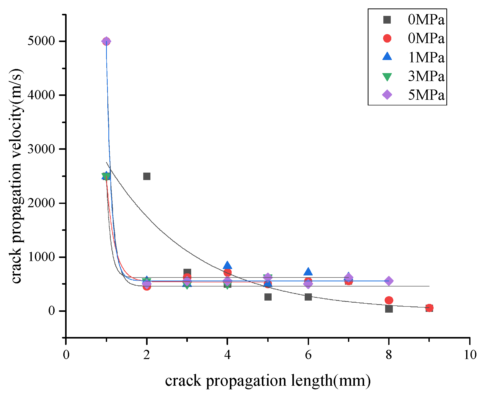
As shown in Table 1, with increasing vertical stress, the average crack propagation speeds for specimens 1, 3, 5, and 7 were 820.32 m/s, 889.74 m/s, 936.12 m/s, and 1114.6 m/s, respectively, indicating that vertical stress promotes the crack propagation speed. The crack propagation velocity under different vertical stresses is shown in Figure 4. Except for some dispersion in the crack propagation monitoring data of specimen 1, the overall trend is generally consistent. The explosion shock wave propagates outward from the notched end of the specimen, generating cracks. However, since the energy produced by the explosion is constant, the continuous decay of the shock wave intensity causes the crack tip propagation velocity to decrease with the increasing crack propagation length.
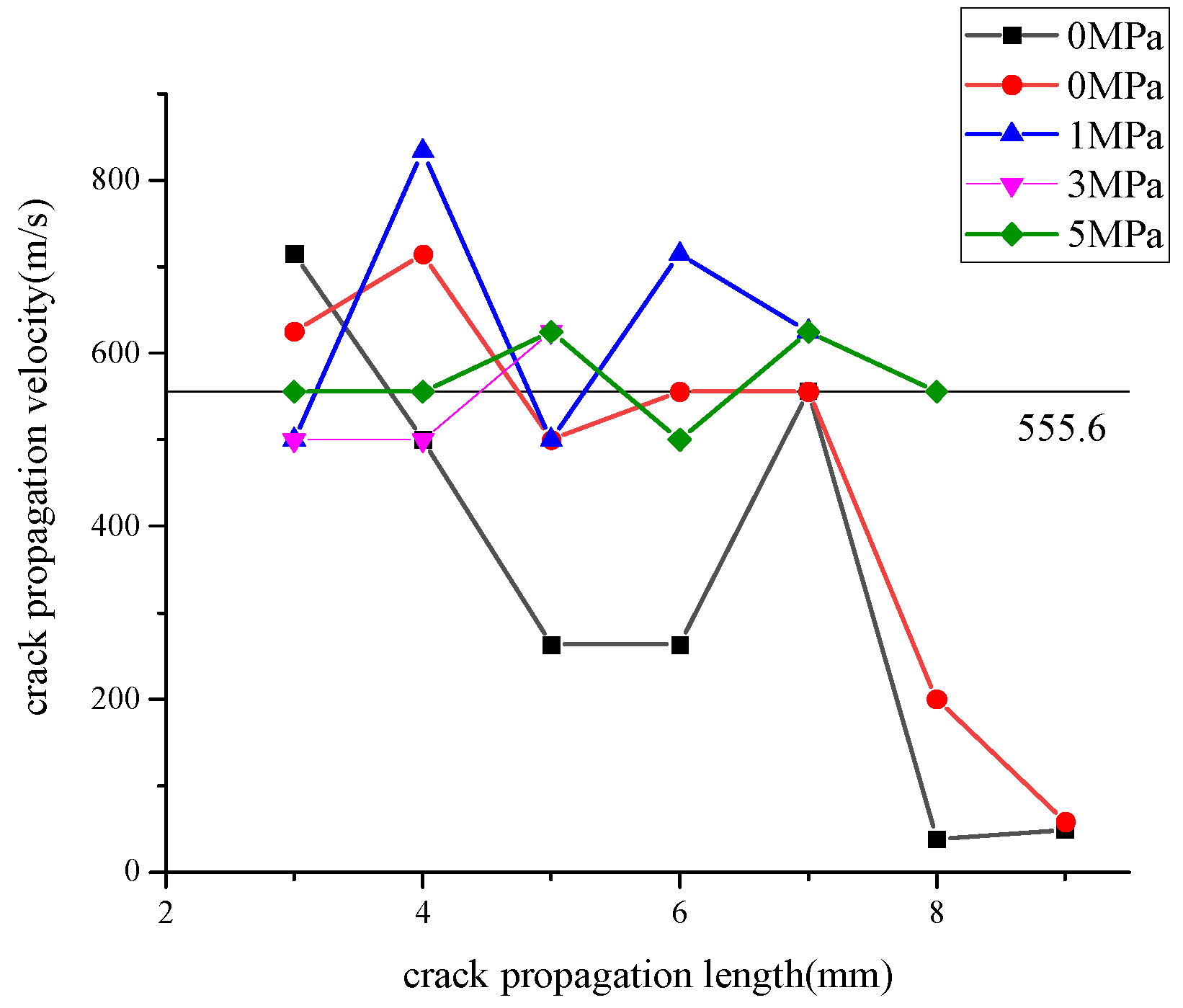
Due to the random damage of the initial segment grid wires of the strain gauges caused by the surface crack propagation, the initial crack propagation velocity is excluded. The subsequent stable propagation process is compared under different vertical stresses, as shown in Figure 5. It is not difficult to observe that as the vertical stress increases from 0 MPa to 5 MPa, the fluctuations in the crack tip propagation velocity gradually become smoother. At 1 MPa, 3 MPa, and 5 MPa they fluctuate within a certain range. As the applied vertical stress increases, the fluctuations in the crack propagation velocity gradually stabilize.
The direction of the groove is parallel to the direction of the vertical stress. The vertical stress enhances the tensile stress in the upper region of the groove and causes a tensile stress concentration near the groove tip, promoting crack propagation. As the crack continues to propagate, the crack propagation resistance decreases, and the energy at the crack tip decays slowly. As shown in Figure 5, as the vertical stress increases, the crack propagation velocity gradually stabilizes at 555.6 m/s with minimal fluctuation, indicating that the vertical stress can effectively stabilize and guide the crack propagation velocity.
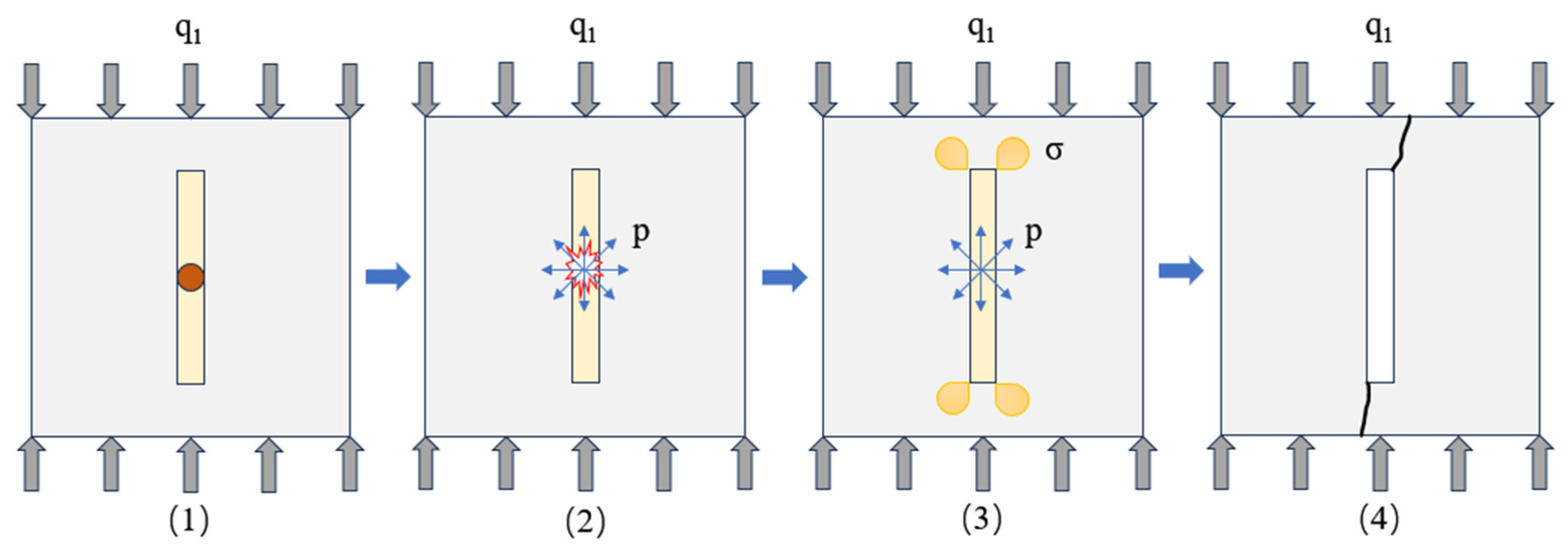
The mechanism of interaction between the vertical stress and blast load is shown in Figure 6. Figure 6(1) shows the gradual increase in vertical stress q1 from the initial state of the specimen until it reaches the set value; Figure 6(2) shows that after the vertical stress loading stabilizes, the explosive is detonated, and the detonation pressure acts outward along the groove, causing significant changes in the internal stress state of the specimen; Figure 6(3) shows the internal stress state of the specimen under the combined action of the detonation pressure and vertical stress, with stress concentrations at the corners of the groove ends, and the effective stress σ gradually increasing to the specimen’s yield strength; and Figure 6(4) shows the final failure mode of the specimen, with cracks forming along the edges of the groove ends and propagating to the specimen’s edges.
The effect of different vertical stresses on the crack propagation is shown in Figure 7. Draw a straight line along the direction of the vertical stress at the center of the slot, then select a crack that deviates significantly from the center. Connect this crack to the end point of the slot with a straight line and observe the angle between the two lines, as shown in Figure 7. It can be seen that as the vertical stress increases, the angle gradually decreases, indicating that the vertical stress has a guiding effect on the crack. Increasing the vertical stress can effectively guide the crack propagation direction, but it also inhibits the propagation speed at the crack tip.
Figure 7(1) and (2) show the crack propagation effect under no loading. Figure 7(3)–(5) show the crack propagation effect under vertical stresses of 1 MPa, 3 MPa, and 5 MPa, respectively.

3. Numerical Simulation

3.1. Model Establishment

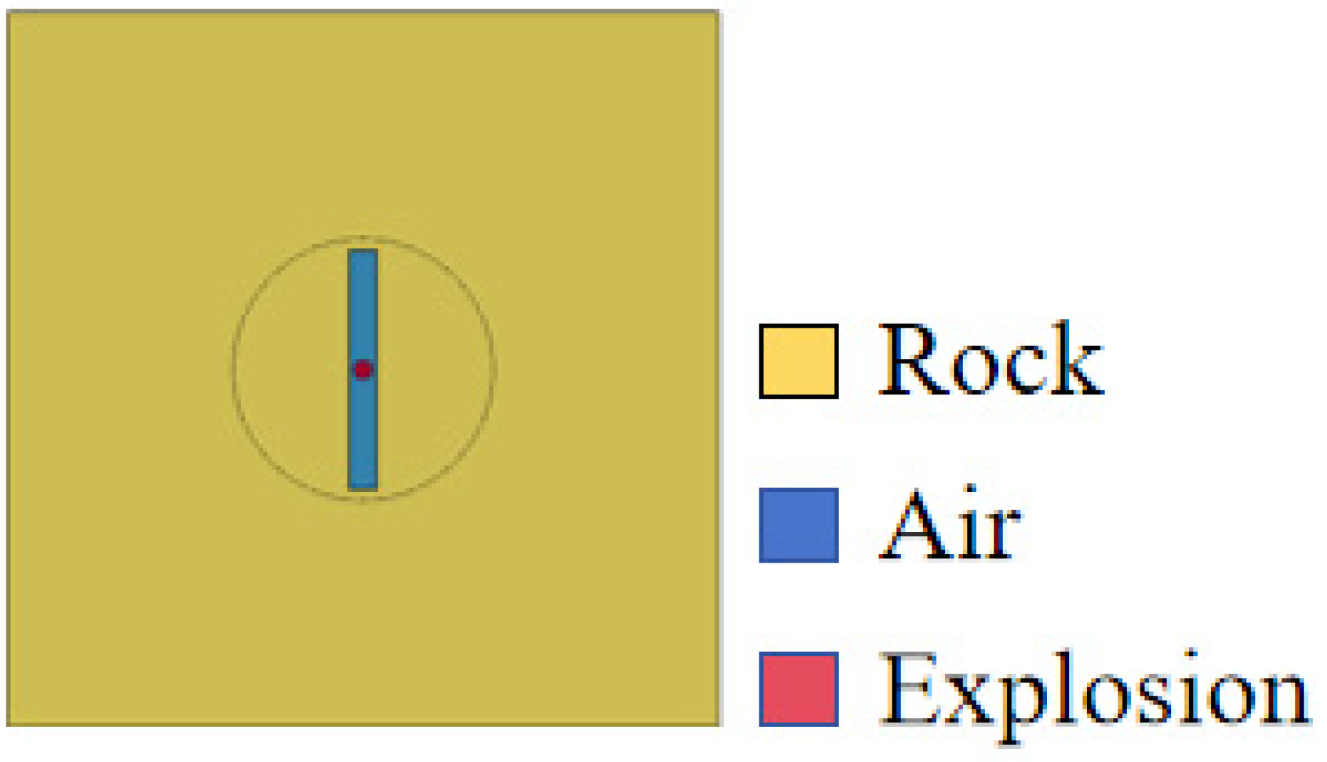
The ANSYS/LS-DYNA R15.0.0 finite element software was used to study the effect of vertical stress on the propagation velocity of fractures in pre-cut grooved concrete (consistent with the experimental specimens). The model was constructed to replicate the experimental setup (Figure 8), with dimensions of 30 × 30 × 10 cm (same as the concrete slab in Section 2.1) and a central prefabricated groove of 10 cm in length, 1.2 cm in width, and 7 cm in depth (matching the groove parameters of the test specimens). Non-reflective boundaries were set around the edges to minimize boundary effects. The calculation was divided into two steps: first, initial stress loads were applied to the upper and lower ends of the rock model to obtain the dynain file, and then the dynain file was used to solve the overall blasting model. The rock material is selected as MAT_RHT, with parameters as shown in Table 2. The explosive is selected as MAT_HIGH_EXPLOSIVE_BURN, with parameters as shown in Table 3. The air is selected as MAT_NULL, with units chosen as g-cm-μs. Four different operating conditions are set, with vertical stresses of 0 MPa, 1 MPa, 3 MPa, and 5 MPa.

3.2. Stress Analysis of Precast Slotted Concrete

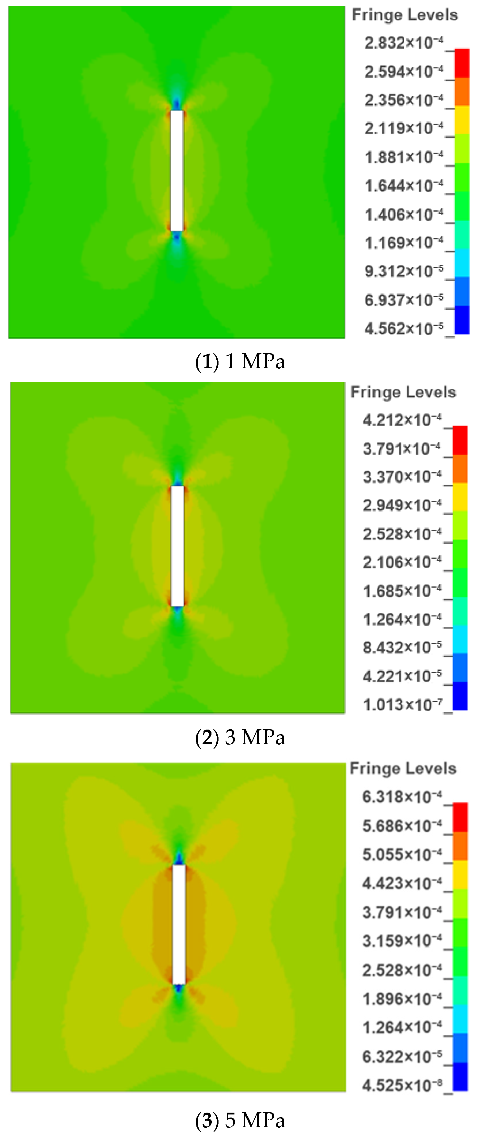
The effective stress cloud diagram of the rock after applying the initial vertical stress to the precast slotted rock is shown in Figure 9. As the stress increases from 0 MPa to 5 MPa, the stress field inside the rock is concentrated near the end of the slot under the action of the slot and vertical load, and the greater the vertical stress, the more obvious it is.
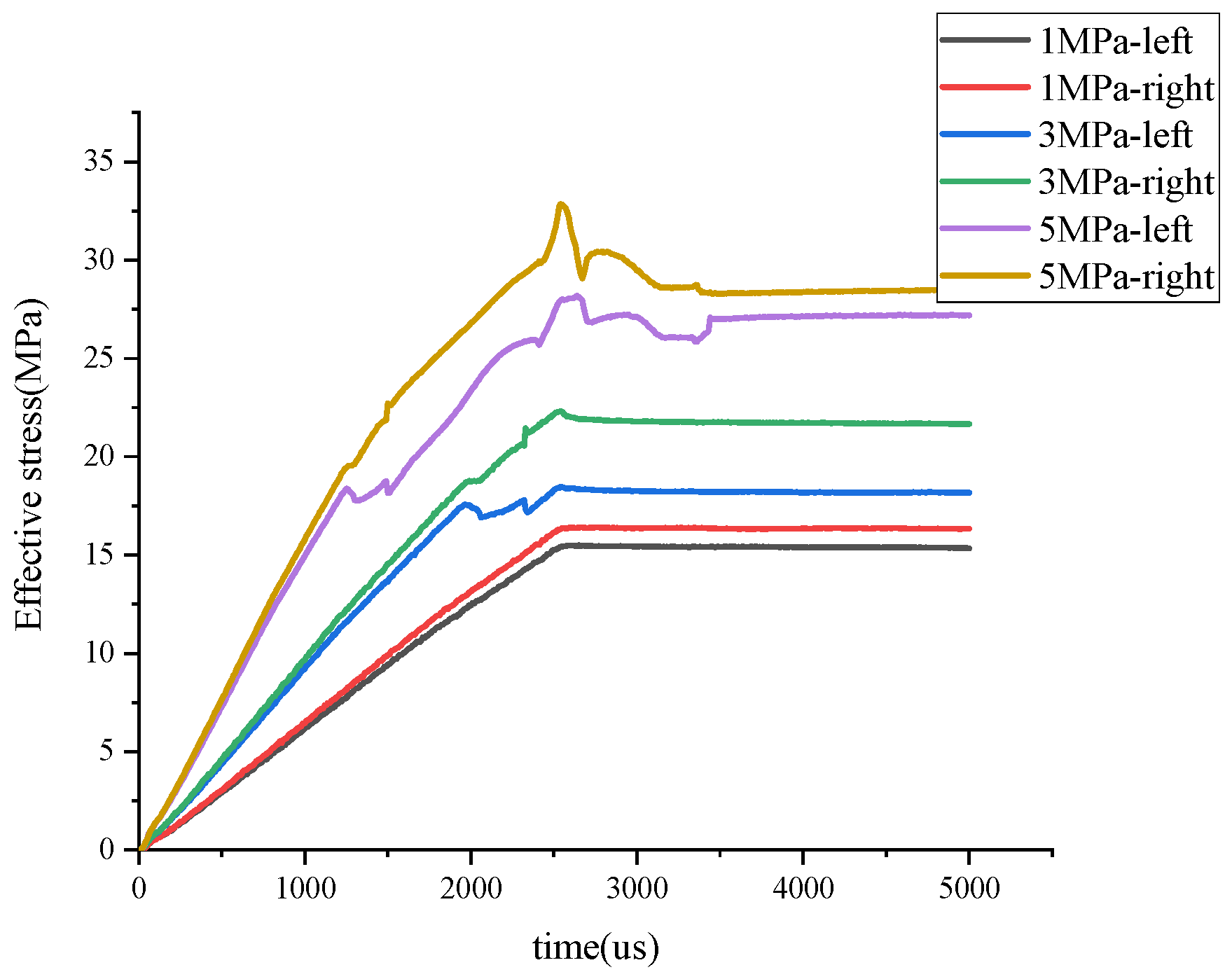
Figure 9(1)–(3) show the effective stress contour plots for pre-notched rock subjected to vertical stresses of 1 MPa, 3 MPa, and 5 MPa, respectively. As shown in Figure 9(1)–(3), the effective stress distribution at the corners of the groove ends increases gradually with the increasing load. The effective stress at the corners on both sides of the groove end is shown in Figure 10. Taking the upper end of the groove as an example, combined with Figure 10, the final effective stresses at the corners on both sides of the groove end at 1 MPa are 15.35 MPa and 16.33 MPa from left to right, respectively. At 3 MPa, the maximum effective stresses at the corners on both sides of the groove end are 18.16 MPa and 21.65 MPa, respectively, from left to right. At 5 MPa, the maximum effective stresses at the corners on both sides of the groove end are 27.19 MPa and 28.49 MPa, respectively, from left to right. As the vertical stress increases, the final effective stress at the corners on both sides of the groove end increases significantly, and the final effective stress at the right corner of the groove end is higher. Therefore, after the explosion, the cracks initiate at the right corner of the groove end and propagate outward, consistent with the experimental results in Figure 7, and increase with the vertical stress.

3.3. Crack Propagation Simulation Results

The crack propagation simulation results are shown in Figure 11 below.
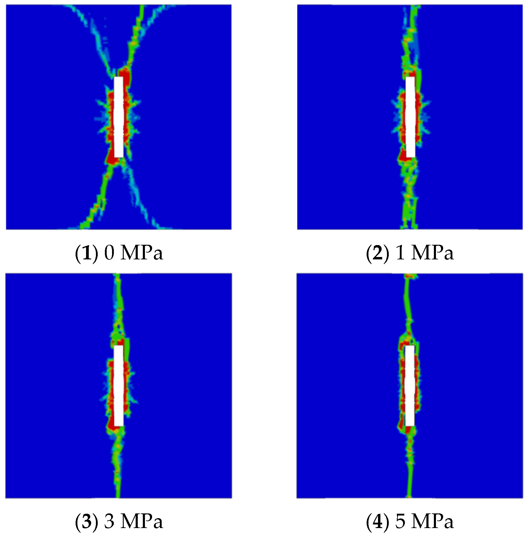
As shown in Figure 11, as the vertical stress increases from 0 MPa to 5 MPa, the horizontal cracks decrease in size and eventually disappear, indicating that secondary cracks in the non-principal stress direction are suppressed. The primary cracks propagate along the pre-cut grooves and in the principal stress direction, consistent with the results of the model experiments, objectively reflecting the guiding effect of the principal stress on the crack propagation.
As the vertical pressure increases, the deviation in the crack propagation direction gradually decreases and becomes increasingly vertical, while secondary cracks also gradually decrease. The crack simulation results validate the model test results. As vertical stress increases, the crack propagation direction transitions from multiple oblique streams to a single straight vertical stream, gradually aligning parallel to the vertical stress, clearly demonstrating the strong guiding effect of vertical stress on cracks. Additionally, as the vertical stress increases, the damage zone around the groove (concrete fracture zone) also gradually decreases, consistent with the research results of Yang Jianhua et al. [12].
The effective stress at the center of the groove end is analyzed as shown in Figure 12. The crack propagation simulation results (Figure 11) are consistent with the experimental observations in Section 2.2, showing that vertical stress reduces crack direction deviation and stabilizes the propagation velocity. The peak values of the effective stress curves under various load conditions are 12.29 MPa, 10.89 MPa, 10.71 MPa, and 12.47 MPa, respectively, with corresponding times of 19.936 us, 19.950 us, 19.955 us, and 29.99 us, respectively. As stress increases, the effective stress at the end of the groove shows an overall increasing trend. Due to the significant stress concentration at the end of the groove, the increasing vertical stress promotes crack propagation.
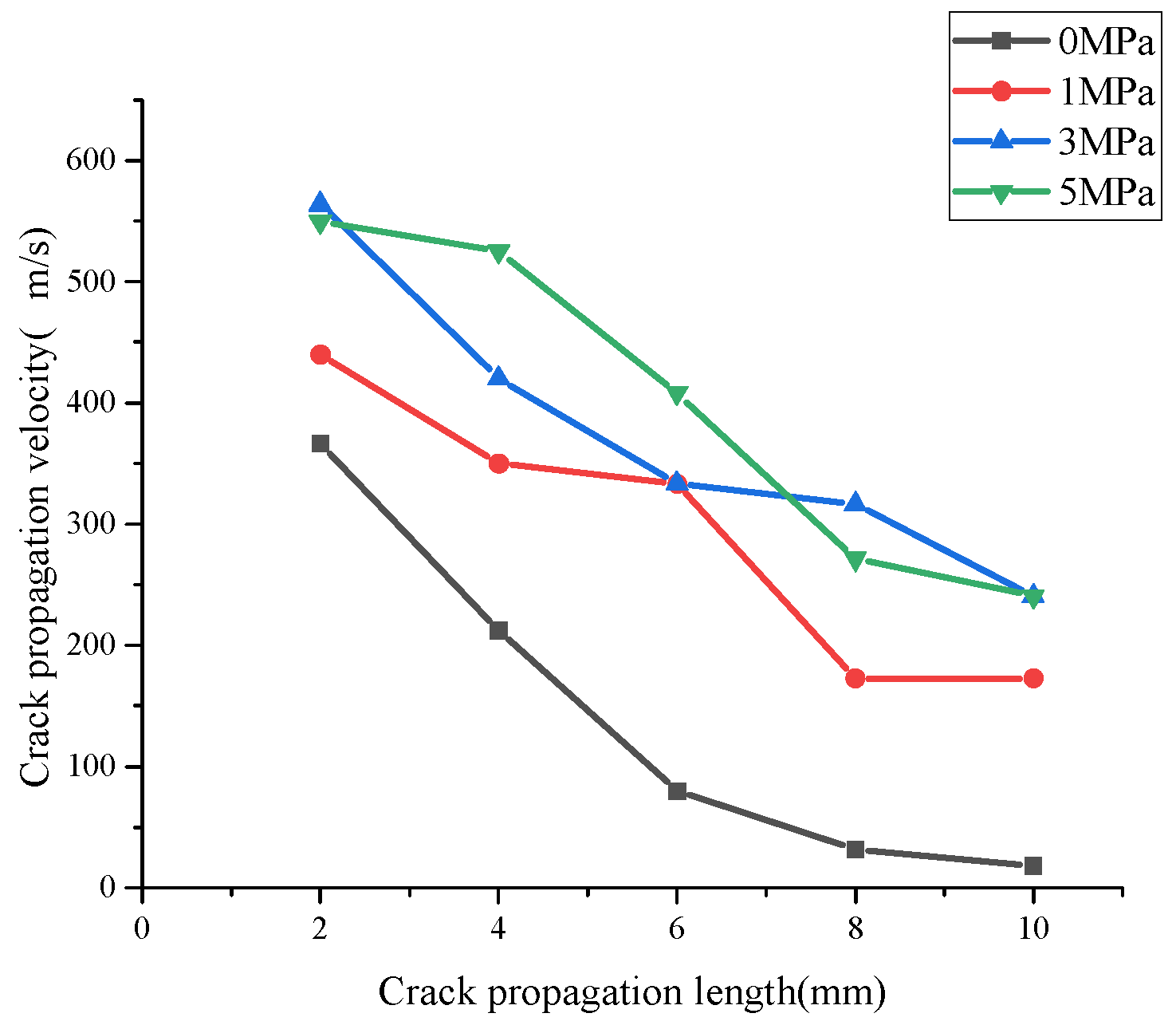
Based on the results of crack propagation velocity simulations, the average crack propagation velocities at vertical stresses of 0 MPa, 1 MPa, 3 MPa, and 5 MPa were 172.63 m/s, 324 m/s, 408.53 m/s, and 438.65 m/s, respectively, consistent with the results of model tests. The average crack propagation velocity increases with increasing vertical stress. As shown in Figure 13, the crack propagation velocity decreases with an increasing crack propagation length. Within the range of 0 mm to 8 mm, at 0 MPa, the crack propagation velocity decreases sharply, with a decrease of 91.36%. However, after applying vertical stress at 1 MPa the decrease in the crack propagation velocity reaches 60.75%, at 3 MPa the decrease reaches 43.86%, and at 5 MPa the decay rate reaches 50.66%. At 10 mm, the crack propagation speeds at 3 MPa and 5 MPa are similar, indicating that the decay rate of the crack propagation speed slows down as the vertical stress increases and eventually stabilizes, meaning that the vertical stress can stabilize and guide the crack propagation speed.

4. Conclusions

Through the theoretical analysis, model testing, and numerical simulation analysis of the crack propagation velocity characteristics of pre-cut rock under vertical stress, the following conclusions were drawn:
(1) Within the experimental test range, cracks initiate and propagate along the edges of the pre-cut grooves. As the vertical stress increases, the deviation of the crack propagation along the vertical direction from the central groove gradually decreases, indicating that vertical stress can further guide the direction of the crack propagation on the basis of pre-cut grooves.
(2) Model tests show that the peak crack propagation velocity decreases overall as the propagation length increases. As vertical stress increases, the average crack propagation velocity increases. From 0 MPa to 5 MPa, the average crack propagation velocities are 820.32 m/s, 889.74 m/s, 936.12 m/s, and 1114.6 m/s, respectively. While the average crack propagation velocity increases, the overall change in the crack tip velocity is suppressed, and the fluctuations in the crack propagation velocity gradually become more stable.
(3) The theoretical analysis and numerical simulation results further validate the accuracy of the experimental results. Increasing the vertical stress further guides the crack’s vertical propagation, with the average crack propagation velocity increasing. Within the range of 0 mm to 8 mm, from 0 MPa to 5 MPa, the decay rate of the crack propagation velocity reaches 91.36%, 60.75%, 43.86%, and 50.66%, respectively. The degree of the crack propagation velocity decay decreases as vertical stress increases, and the velocity eventually stabilizes. Vertical stress can stably guide the crack propagation velocity.
The experimental data on crack propagation characteristics under vertical stress hold significant implications for the stability and safety of underground engineering structures (e.g., tunnels, mines, and deep caverns). In deep underground environments, rock masses are subject to high in situ stress, and controlled blasting is a common technique for excavation and support. The findings that vertical stress guides the crack propagation direction (reducing deviation from prefabricated grooves) and stabilizes the crack tip velocity provide critical insights:
The directional guidance of vertical stress on blasting cracks can help control the scope of the rock fragmentation, reducing unintended damage to surrounding rock masses and thus enhancing the stability of underground structures.
The suppression of crack tip velocity fluctuations and the gradual stabilization of the velocity (around 555.6 m/s under higher stress) indicate that blasting-induced fractures are less likely to propagate abruptly or unpredictably. This reduces the risk of sudden rock mass failure, which is crucial for preventing collapses or rock bursts in underground engineering.
The slower decay of the crack propagation velocity under increased vertical stress suggests that the energy release during blasting is more controlled, minimizing excessive vibration and stress perturbations to adjacent structures—key factors in ensuring long-term safety in underground projects.
Thus, these experimental results provide a theoretical basis for optimizing blasting parameters in deep underground engineering, contributing to the design of safer and more stable excavation schemes.

4.1. Practical Significance

The research results provide direct theoretical support for controlled blasting in deep underground engineering (e.g., tunnel excavation, mining, and deep cavern construction). By revealing that vertical stress enhances the directional guidance of prefabricated grooves on blasting cracks and stabilizes the crack propagation velocity, this study enables engineers to optimize blasting parameters (e.g., groove layout, explosive dosage) based on in situ stress levels. This can reduce unintended rock damage, minimize the risk of rock bursts, and improve the stability and safety of surrounding structures in high-stress environments.

4.2. Limitations

The current study has certain limitations: (1) The experiments were conducted on concrete specimens (simulating rock), and the mechanical properties of concrete differ from natural rock (e.g., in terms of heterogeneity and porosity), which may affect the direct applicability of results to natural rock masses. (2) The vertical stress range (0–5 MPa) is limited to shallow to medium-depth underground environments, and the crack propagation law under higher in situ stress (e.g., >10 MPa) in ultra-deep engineering remains untested. (3) The prefabricated grooves were designed with fixed dimensions (10 cm length, 1.2 cm width, 7 cm depth), and the interaction between the groove geometry (e.g., length, width, inclination) and vertical stress was not explored.

4.3. Future Research Directions

Future work may focus on the following: (1) Conducting experiments on natural rock specimens (e.g., granite, sandstone) to verify the applicability of the conclusions in heterogeneous geological materials. (2) Expanding the vertical stress range to simulate ultra-deep environments (>10 MPa) and exploring the threshold effect of stress on crack propagation. (3) Investigating the combined influence of the groove geometry (e.g., different inclinations relative to stress direction) and multi-directional in situ stress (not just vertical stress) on blasting crack behavior. (4) Integrating field monitoring data from actual underground projects to validate the experimental findings and develop engineering-oriented prediction models for controlled blasting.

5. Discussion

5.1. Correspondence Between Experimental Data and Numerical Simulation Results

This study combined model tests and ANSYS/LS-DYNA numerical simulations to explore the expansion characteristics of blasting cracks in prefabricated grooved rocks under vertical stresses. The high consistency between the experimental data and simulation results verifies the reliability of the research conclusions, which is specifically reflected in three aspects: the crack propagation direction, crack expansion velocity, and stress distribution law.

5.1.1. Crack Propagation Direction

In the model test, as the vertical stress increased from 0 MPa to 5 MPa, the deviation angle of cracks from the center of the prefabricated groove in the vertical direction gradually decreased (from approximately 18° to 7°, Figure 7). This indicates that vertical stress can further guide the crack propagation direction on the basis of the prefabricated groove. The numerical simulation results (Figure 11) show the same trend: with the increase in vertical stress, horizontal secondary cracks gradually decrease and eventually disappear, while the main cracks propagate along the direction of the prefabricated groove and the principal stress.
The consistency in the crack direction is due to the fact that both the test and simulation fully consider the stress concentration effect at the end of the prefabricated groove. In the experiment, the vertical stress enhances the tensile stress concentration at the groove tip, promoting cracks to extend along the vertical direction; in the numerical model, the MAT_RHT material parameter settings (Table 2) accurately simulate the tensile failure characteristics of rock-like materials, and the non-reflective boundary conditions effectively avoid the interference of boundary reflection waves on the crack direction, thus reproducing the guiding effect of vertical stress on cracks.

5.1.2. Crack Expansion Velocity

The experimental results show that the average crack expansion velocity increases with the increase in vertical stress: the average velocities under 0 MPa, 1 MPa, 3 MPa, and 5 MPa are 820.32 m/s, 889.74 m/s, 936.12 m/s, and 1114.6 m/s, respectively (Table 1). At the same time, the crack expansion velocity shows a decreasing trend with the increase in the crack length, and the decay rate slows down with the increase in vertical stress (e.g., the decay rate within 0–8 mm decreases from 91.36% at 0 MPa to 43.86% at 3 MPa).
The numerical simulation results (Figure 13) are highly consistent with the experimental data. The simulated average crack expansion velocities under the four vertical stress levels are 172.63 m/s, 324 m/s, 408.53 m/s, and 438.65 m/s, respectively. Although the absolute values of the simulated velocities are lower than the experimental values, the changing trend of “increasing with vertical stress and decreasing with crack length” is completely consistent with the experiment. The difference in absolute values is mainly because the numerical model simplifies the inhomogeneity of the concrete specimen (such as the random distribution of aggregates), while the actual specimen has a local stress concentration caused by aggregate–matrix interfaces, which leads to a higher crack initiation and propagation speed in the experiment. However, this difference does not affect the reliability of the changing law of the crack expansion velocity obtained in the study.

5.1.3. Stress Distribution Law

In the model test, the stress concentration at the end of the prefabricated groove is the main reason for crack initiation. The experimental phenomenon shows that cracks first initiate at the corner of the groove end and then propagate outward. The numerical simulation further quantifies this stress concentration effect: as the vertical stress increases from 1 MPa to 5 MPa, the maximum effective stress at the corner of the groove end increases from 15.35 to 16.33 MPa to 27.19–28.49 MPa (Figure 10), and the stress at the right corner is always higher than that at the left corner, which is consistent with the experimental observation that “cracks first initiate at the right corner of the groove end”.
This consistency confirms that the numerical model accurately simulates the stress state of the prefabricated grooved rock under the coupling action of the vertical stress and blasting load. The MAT_HIGH_EXPLOSIVE_BURN material model (Table 3) used for explosives can reliably reproduce the detonation pressure propagation process, and the step-by-step calculation method (first applying initial stress to obtain the dynain file, then solving the blasting model) ensures that the influence of vertical stress on the rock stress field is fully considered, thus making the simulated stress distribution law consistent with the experimental results.

5.2. Key Characteristics of Aggregates in Experimental Concrete

The experimental model (30 × 30 × 10 cm concrete slab, 17.8 MPa compressive strength) was designed to simulate deep surrounding rock. Its aggregate properties, critical for analyzing crack behavior, are specified below: Coarse aggregate: Crushed granite stone with a particle size of 5–15 mm (matching medium-grained rock), an elastic modulus of 35–40 GPa, and a tensile strength of 8–10 MPa—all higher than the mortar matrix (elastic modulus: 15–20 GPa; tensile strength: 2–3 MPa). Fine aggregate: Natural river sand with a fineness modulus of 2.3–2.6 (medium sand), mixed with cement at a 2.5:1 mass ratio to form the mortar matrix, ensuring good bonding with coarse aggregates.

Mechanisms of Aggregate Effects on Crack Expansion Rate

Combined with experimental results under 0 MPa, 1 MPa, 3 MPa, and 5 MPa vertical stresses, the influences of aggregate characteristics are analyzed as follows:
Coarse aggregates act as “mechanical barriers” due to their high strength:
Low vertical stress (0–1 MPa): Blasting shock waves dominate crack propagation. Cracks tend to deflect along the aggregate–matrix interface instead of penetrating high-strength aggregates, increasing the propagation path. This causes significant crack tip velocity decay and an uneven velocity due to non-uniform aggregate distributions.
High vertical stress (3–5 MPa): Vertical stress enhances the tensile stress concentration at the groove tip and increases the interface bonding strength to ~2.5–3 MPa. Cracks are more likely to penetrate aggregates, reducing path tortuosity. This slows the velocity decay and stabilizes the velocity at ~555.6 m/s.
The uniform gradation of fine aggregates ensures a dense mortar matrix (void ratio < 3%), avoiding local weak areas (e.g., pores) that could cause false strain signals and ensuring reliable strain gauge tests. Additionally, the fine aggregate matrix acts as a “stress buffer” between coarse aggregates, transferring stress uniformly under vertical stress, reducing the interface stress concentration, and suppressing secondary horizontal cracks.
Vertical stress regulates aggregate–matrix bonding, affecting the crack deviation from the prefabricated groove: Low stress (0 MPa): Weak bonding leads to random crack deflection along interfaces, increasing the deviation. High stress (5 MPa): Strong bonding restricts random deflections, forcing cracks to propagate linearly along the groove (parallel to vertical stress) through aggregates, reducing the deviation.
Engineering implications: For deep engineering with high vertical stress (>3 MPa), using high-strength coarse aggregates (e.g., granite) and medium sand can stabilize crack expansion rates. Prefabricated groove paths should avoid coarse aggregate agglomerations (detectable via non-destructive testing) to prevent local deviations.
Limitations: This study fixed aggregate parameters (particle size, gradation). Future research could use orthogonal experiments to quantify the coupling effect of aggregate parameters and vertical stress.

5.3. Practical Significance of the Obtained Results

The research results of this study have important practical value for guiding the design of directional blasting in deep rock engineering and can provide scientific support for solving key technical problems in deep resource development, tunnel construction, and water conservancy project construction.

5.3.1. Guiding the Optimization of Directional Blasting Parameters in Deep Engineering

Deep rock engineering is often in a high in situ stress environment, and the direction and speed of blasting cracks are difficult to control, which easily leads to problems such as over-excavation, under-excavation, and rock burst. This study found that vertical stress can guide the direction of crack propagation and stabilize the crack expansion velocity on the basis of prefabricated grooves. This conclusion can be used to optimize the blasting parameters of deep engineering:
For deep rock with high vertical stress (such as 3–5 MPa), the prefabricated groove parameters (length, width, depth) can be adjusted according to the magnitude of the vertical stress to further enhance the guiding effect of the groove on cracks. For example, in rock with a vertical stress of 5 MPa, a prefabricated groove with a depth of 7–8 cm can be adopted to ensure that the crack deviation angle is controlled within 10°, reducing the risk of over-excavation.
The average crack expansion velocity increases with the increase in vertical stress. In engineering, the charge amount of explosives can be adjusted according to the vertical stress level. For rock with high vertical stress, the charge amount can be appropriately reduced to avoid an excessive crack expansion velocity leading to excessive rock fragmentation and increased engineering cost.

5.3.2. Promoting the Application of Water Jet Grooving Technology in Deep Blasting

Water jet grooving is an efficient prefabricated groove-forming technology, but its application effect in deep high-stress rock is not clear. This study confirms that prefabricated grooves can effectively guide the direction of blasting cracks, and vertical stress can further enhance this guiding effect. This result provides a theoretical basis for the application of water jet grooving technology in deep blasting:
In deep tunnel excavation, water jet grooving can be used to prefabricate grooves along the design contour line of the tunnel. Under the action of vertical in situ stress, the blasting cracks will propagate along the prefabricated grooves, forming a smooth tunnel contour, reducing the damage to the surrounding rock, and improving the stability of the tunnel.
In deep mineral mining, water jet grooving can be used to prefabricate directional cracks in the ore body. Under the action of vertical stress, the cracks will expand stably along the preset direction, improving the mining efficiency and reducing the loss of ore resources.

5.3.3. Providing a Reference for the Prediction and Prevention of Deep Rock Engineering Disasters

The unstable propagation of blasting cracks is one of the important causes of deep rock engineering disasters such as rock bursts and roof falls. This study found that the decay rate of the crack expansion velocity slows down with the increase in vertical stress, and the velocity eventually stabilizes at approximately 555.6 m/s. This law can be used to predict the propagation range and speed of blasting cracks in deep rock:
By establishing the relationship between the vertical stress and crack expansion velocity decay rate, engineers can predict the maximum propagation distance of blasting cracks according to the in situ stress level of the project, avoid the cracks propagating to the surrounding rock mass that needs to be protected, and prevent the occurrence of rock bursts.
The stable crack expansion velocity obtained in the study can be used as a reference for the design of deep rock support structures. By calculating the impact force of the rock mass caused by stable crack propagation, the support parameters (such as the type and spacing of bolts) can be optimized to improve the support effect and ensure the safety of the project.

Author Contributions

Conceptualization, M.W. and Q.D.; methodology, M.W. and Q.D.; software, M.W. and Q.D.; validation, M.W. and Q.D.; formal analysis, M.W. and Q.D.; investigation, M.W. and Q.D.; resources, M.W. and Q.D.; data curation, M.W. and Q.D.; writing—original draft preparation, M.W. and Q.D.; writing—review and editing, M.W. and Q.D.; visualization, M.W. and Q.D.; supervision, M.W. and Q.D.; project administration, M.W. and Q.D.; funding acquisition, M.W. and Q.D. All authors have read and agreed to the published version of the manuscript.

Funding

This work is supported by the Foundation of Hubei Key Laboratory of Blasting Engineering (No. BL2021-20), Study on the Dynamic Rock Breaking Mechanism of Explosives and Impedance Media Coupling in High-Stress Environments (grant number JYBGCZX2022104), and Natural Science Research Project of Anhui Educational Committee (grant number 2022AH050841).

Data Availability Statement

The datasets used and/or analyzed during the current study are available from the corresponding author on reasonable request.

Conflicts of Interest

The authors declare that this study was conducted without any commercial or financial relationships that could be construed as a potential conflict of interest.

References

  1. Pan, J.; Ma, W.; Liu, S.; Gao, J.M. A prevention technology of rock burst based on directional presplitting of water jet prefabricated slot in hard roof. Chin. J. Rock Mech. Eng. 2021, 40, 1591–1602. [Google Scholar] [CrossRef]
  2. Zhang, Y.; Guo, S. Theoretical model of annular slotting depth for high pressure water jet and its application. J. China Coal Soc. 2019, 44 (Suppl. S1), 126–132. [Google Scholar] [CrossRef]
  3. Wang, G.; Fan, J.Y.; Wang, W.R.; Xu, H. Slot spacing model of directional fracturing coal assitd by hydraulic slotting. J. Min. Saf. Eng. 2020, 37, 622–631. [Google Scholar] [CrossRef]
  4. Zhang, Z. On the initiating, Glowing branching and sloping of crack in rock blasting. Blasting 1999, 16, 21–24. [Google Scholar]
  5. Chen, J. Monitoring analysis for the velocity of crack propagation. Chin. J. Rock Mech. Eng. 1998, 17, 77–80. [Google Scholar]
  6. Zhang, Z. An Experimental Study of Crack Expansion Speed in Rock Blasting. Explos. Mater. 2000, 29, 1–8. [Google Scholar]
  7. Li, Q.; Gao, Z.H.; Xu, W.L.; Wang, K.; Liu, S.; Ran, G.F.; Hu, Y. Experimental research on the dynamic propagation process of mode I cracks in the rock under directional fracture blasting using the strain gauge method. Eng. Fract. Mech. 2020, 235, 107113. [Google Scholar] [CrossRef]
  8. Liu, R.F.; Zhu, Z.M.; Li, Y.X.; Liu, B.; Wan, D.; Li, M. Study of rock dynamic fracture toughness and crack propaga tion parameters of four brittle materials under blasting. Eng. Fract. Mech. 2020, 225, 106460. [Google Scholar] [CrossRef]
  9. Zou, X.-W.; Zhou, T.; Li, G.; Hu, Y.; Deng, B.; Yang, T. Intelligent Inversion Analysis of Surrounding Rock Parameters and Deformation Characteristics of a Water Diversion Surge Shaft. Designs 2024, 8, 116. [Google Scholar] [CrossRef]
  10. Liu, R.; Zhu, Z.; Du, Y.; Li, M.; Liu, B.; Wan, D. Study on dynamic propagation law of cracks with different lengths under blasting. Chin. J. Rock Mech. Eng. 2022, 41 (Suppl. S2), 3114–3123. [Google Scholar]
  11. Xie, H. Research review of the state key research development program of China: Deep rock mechanics and mining theory. J. China Coal Soc. 2019, 44, 1283–1305. [Google Scholar]
  12. Xiao, S.Y.; Jiang, Y.J.; Liu, Z.X.; Su, L.J. Hard rock blasting energy distribution and frag mentation characteristics under high earth stress. J. Vib. Shock 2018, 37, 143–149. [Google Scholar]
  13. Yang, J.; Wu, Z.; Yao, C.; Jiang, S.; Jiang, Q. Influences of in-situ stress on blast-induced rock fracture and seismic waves. J. Vib. Shock 2020, 39, 64–70+90. [Google Scholar]
  14. Li, X.D.; Liu, K.W.; Sha, Y.Y.; Yang, J.; Ma, S.; Hong, Z. Investigation on radial fracturing around borehole under combined static stress and blasting. Theor. Appl. Fract. Mech. 2023, 127, 104038. [Google Scholar] [CrossRef]
  15. Tao, J.; Yang, X.G.; Li, H.T.; Zhou, J.W.; Fan, G.; Lu, G.D. Effects of in-situ stresses on dynamic rock responses under blast loading. Mech. Mater. 2020, 145, 103374. [Google Scholar] [CrossRef]
  16. Ma, W.-B.; Zou, W.-H.; Zhang, J.-L.; Li, G. Prediction of Shear Strength in Anisotropic Structural Planes Considering Size Effects. Designs 2025, 9, 17. [Google Scholar] [CrossRef]
  17. Yang, R.; Su, H. Experimental study on crack propagation with pre-crack under explosion load. J. China Coal Soc. 2019, 44, 482–489. [Google Scholar]
  18. Ge, J.; Xu, Y.; Cheng, L. Relationship between in-situ stress and propagation direction of main cracks induced by blasting. J. Vib. Shock 2023, 42, 54–64. [Google Scholar]
  19. Yue, Z.; Tian, S.; Zhang, S. Experimental study of crack propagation under blasting load in notched boreholes. J. Vib. Shock 2019, 38, 186–195. [Google Scholar]
  20. Yang, L.; Wang, Q.; Ding, C. Experimental analysis on the mechanism of slotting blasting in deep rock mass. J. Vib. Shock 2020, 39, 40–46. [Google Scholar]
  21. Yang, R.; Ding, C.; Li, Y.; Yang, L.; Zhao, Y. Crack propagation behavior in slit charge blasting under high static stress conditions. Int. J. Rock Mech. Min. Sci. 2019, 119, 117–123. [Google Scholar] [CrossRef]
  22. Yang, L.; Huang, C.; Bao, S.; Zhang, L. Model experimental study on controlled blasting of slit charge in deep rock mass. Soil Dyn. Earthq. Eng. 2020, 138, 106318. [Google Scholar] [CrossRef]
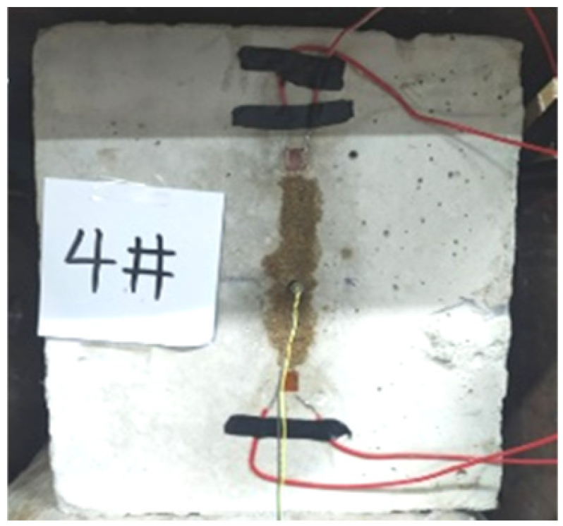
Figure 1. Vertical stress crack expansion rate specimen.
Applsci 15 09747 g001
Figure 2. Experimental setup.
Applsci 15 09747 g002
Figure 3. Crack expansion strain gauge test results under different vertical stresses.
Applsci 15 09747 g003aApplsci 15 09747 g003b
Figure 4. Decay law of crack expansion rate under different vertical stresses.
Applsci 15 09747 g004
Figure 5. Crack expansion rate under different vertical stresses.
Applsci 15 09747 g005
Figure 6. Mechanism of vertical stress coupled with blasting loads.
Applsci 15 09747 g006
Figure 7. Effect of crack extension by different vertical stress blasting.
Applsci 15 09747 g007
Figure 8. Model program.
Applsci 15 09747 g008
Figure 9. Effective stress cloud map of prefabricated groove rock under vertical stress.
Applsci 15 09747 g009
Figure 10. Effective stress at corners on both sides of grooved ends.
Applsci 15 09747 g010
Figure 11. Crack extension simulation results.
Applsci 15 09747 g011
Figure 12. Effective stress at center of grooved end.
Applsci 15 09747 g012
Figure 13. Crack extension rate simulation results.
Applsci 15 09747 g013
Table 1. Crack expansion rate of specimen.
Specimen12357
Extended
Length
Time/usVelocity/(m/s)Time/usVelocity/(m/s)Time/usVelocity/(m/s)Time/usVelocity/(m/s)Time/usVelocity/(m/s)
1 mm0.425000.250000.425000.425000.25000
2 mm0.425002.2454.51.8555.61.8555.62.0500.0
3 mm1.4714.31.6625.02500.02.0500.01.8555.6
4 mm2500.01.4714.31.2833.32.0500.01.8555.6
5 mm3.8263.22.0500.02500.01.6625.01.6625.0
6 mm3.8263.21.8555.61.4714.3//2.0500.0
7 mm1.8555.61.8555.61.6625.0//1.6625.0
8 mm2638.505.0200.0////1.8555.6
9 mm20.848.0817.258.14// ///
Average speed 820.32 962.57 889.74 936.12 1114.6
Table 2. Rock RHT parameters.
ρ (g/cm3)E/GPa f c /MPa f s f t
1.971017.80.380.1
Table 3. Explosive parameters.
ρ (g/cm3)D (cm/μs)Pcj/GPaabr1r2
1.500.3595.32.7620.08445.22.1
Disclaimer/Publisher’s Note: The statements, opinions and data contained in all publications are solely those of the individual author(s) and contributor(s) and not of MDPI and/or the editor(s). MDPI and/or the editor(s) disclaim responsibility for any injury to people or property resulting from any ideas, methods, instructions or products referred to in the content.